EP2752249A1 - Fluid control valve and sprayhead with such a valve - Google Patents
Fluid control valve and sprayhead with such a valve Download PDFInfo
- Publication number
- EP2752249A1 EP2752249A1 EP14150082.7A EP14150082A EP2752249A1 EP 2752249 A1 EP2752249 A1 EP 2752249A1 EP 14150082 A EP14150082 A EP 14150082A EP 2752249 A1 EP2752249 A1 EP 2752249A1
- Authority
- EP
- European Patent Office
- Prior art keywords
- disc
- outlet
- sprayhead
- outlet port
- fluid
- Prior art date
- Legal status (The legal status is an assumption and is not a legal conclusion. Google has not performed a legal analysis and makes no representation as to the accuracy of the status listed.)
- Withdrawn
Links
Images








Classifications
-
- B—PERFORMING OPERATIONS; TRANSPORTING
- B05—SPRAYING OR ATOMISING IN GENERAL; APPLYING FLUENT MATERIALS TO SURFACES, IN GENERAL
- B05B—SPRAYING APPARATUS; ATOMISING APPARATUS; NOZZLES
- B05B1/00—Nozzles, spray heads or other outlets, with or without auxiliary devices such as valves, heating means
- B05B1/30—Nozzles, spray heads or other outlets, with or without auxiliary devices such as valves, heating means designed to control volume of flow, e.g. with adjustable passages
- B05B1/32—Nozzles, spray heads or other outlets, with or without auxiliary devices such as valves, heating means designed to control volume of flow, e.g. with adjustable passages in which a valve member forms part of the outlet opening
- B05B1/326—Gate valves; Sliding valves; Cocks
-
- B—PERFORMING OPERATIONS; TRANSPORTING
- B05—SPRAYING OR ATOMISING IN GENERAL; APPLYING FLUENT MATERIALS TO SURFACES, IN GENERAL
- B05B—SPRAYING APPARATUS; ATOMISING APPARATUS; NOZZLES
- B05B1/00—Nozzles, spray heads or other outlets, with or without auxiliary devices such as valves, heating means
- B05B1/14—Nozzles, spray heads or other outlets, with or without auxiliary devices such as valves, heating means with multiple outlet openings; with strainers in or outside the outlet opening
- B05B1/16—Nozzles, spray heads or other outlets, with or without auxiliary devices such as valves, heating means with multiple outlet openings; with strainers in or outside the outlet opening having selectively- effective outlets
- B05B1/1627—Nozzles, spray heads or other outlets, with or without auxiliary devices such as valves, heating means with multiple outlet openings; with strainers in or outside the outlet opening having selectively- effective outlets with a selecting mechanism comprising a gate valve, a sliding valve or a cock
- B05B1/1636—Nozzles, spray heads or other outlets, with or without auxiliary devices such as valves, heating means with multiple outlet openings; with strainers in or outside the outlet opening having selectively- effective outlets with a selecting mechanism comprising a gate valve, a sliding valve or a cock by relative rotative movement of the valve elements
-
- B—PERFORMING OPERATIONS; TRANSPORTING
- B05—SPRAYING OR ATOMISING IN GENERAL; APPLYING FLUENT MATERIALS TO SURFACES, IN GENERAL
- B05B—SPRAYING APPARATUS; ATOMISING APPARATUS; NOZZLES
- B05B1/00—Nozzles, spray heads or other outlets, with or without auxiliary devices such as valves, heating means
- B05B1/02—Nozzles, spray heads or other outlets, with or without auxiliary devices such as valves, heating means designed to produce a jet, spray, or other discharge of particular shape or nature, e.g. in single drops, or having an outlet of particular shape
-
- B—PERFORMING OPERATIONS; TRANSPORTING
- B05—SPRAYING OR ATOMISING IN GENERAL; APPLYING FLUENT MATERIALS TO SURFACES, IN GENERAL
- B05B—SPRAYING APPARATUS; ATOMISING APPARATUS; NOZZLES
- B05B1/00—Nozzles, spray heads or other outlets, with or without auxiliary devices such as valves, heating means
- B05B1/14—Nozzles, spray heads or other outlets, with or without auxiliary devices such as valves, heating means with multiple outlet openings; with strainers in or outside the outlet opening
- B05B1/18—Roses; Shower heads
-
- B—PERFORMING OPERATIONS; TRANSPORTING
- B05—SPRAYING OR ATOMISING IN GENERAL; APPLYING FLUENT MATERIALS TO SURFACES, IN GENERAL
- B05B—SPRAYING APPARATUS; ATOMISING APPARATUS; NOZZLES
- B05B1/00—Nozzles, spray heads or other outlets, with or without auxiliary devices such as valves, heating means
- B05B1/30—Nozzles, spray heads or other outlets, with or without auxiliary devices such as valves, heating means designed to control volume of flow, e.g. with adjustable passages
- B05B1/3026—Gate valves; Sliding valves; Cocks
-
- B—PERFORMING OPERATIONS; TRANSPORTING
- B05—SPRAYING OR ATOMISING IN GENERAL; APPLYING FLUENT MATERIALS TO SURFACES, IN GENERAL
- B05B—SPRAYING APPARATUS; ATOMISING APPARATUS; NOZZLES
- B05B12/00—Arrangements for controlling delivery; Arrangements for controlling the spray area
- B05B12/002—Manually-actuated controlling means, e.g. push buttons, levers or triggers
-
- B—PERFORMING OPERATIONS; TRANSPORTING
- B05—SPRAYING OR ATOMISING IN GENERAL; APPLYING FLUENT MATERIALS TO SURFACES, IN GENERAL
- B05B—SPRAYING APPARATUS; ATOMISING APPARATUS; NOZZLES
- B05B7/00—Spraying apparatus for discharge of liquids or other fluent materials from two or more sources, e.g. of liquid and air, of powder and gas
- B05B7/02—Spray pistols; Apparatus for discharge
- B05B7/12—Spray pistols; Apparatus for discharge designed to control volume of flow, e.g. with adjustable passages
-
- Y—GENERAL TAGGING OF NEW TECHNOLOGICAL DEVELOPMENTS; GENERAL TAGGING OF CROSS-SECTIONAL TECHNOLOGIES SPANNING OVER SEVERAL SECTIONS OF THE IPC; TECHNICAL SUBJECTS COVERED BY FORMER USPC CROSS-REFERENCE ART COLLECTIONS [XRACs] AND DIGESTS
- Y10—TECHNICAL SUBJECTS COVERED BY FORMER USPC
- Y10T—TECHNICAL SUBJECTS COVERED BY FORMER US CLASSIFICATION
- Y10T137/00—Fluid handling
- Y10T137/8593—Systems
- Y10T137/86493—Multi-way valve unit
- Y10T137/86549—Selective reciprocation or rotation
-
- Y—GENERAL TAGGING OF NEW TECHNOLOGICAL DEVELOPMENTS; GENERAL TAGGING OF CROSS-SECTIONAL TECHNOLOGIES SPANNING OVER SEVERAL SECTIONS OF THE IPC; TECHNICAL SUBJECTS COVERED BY FORMER USPC CROSS-REFERENCE ART COLLECTIONS [XRACs] AND DIGESTS
- Y10—TECHNICAL SUBJECTS COVERED BY FORMER USPC
- Y10T—TECHNICAL SUBJECTS COVERED BY FORMER US CLASSIFICATION
- Y10T137/00—Fluid handling
- Y10T137/8593—Systems
- Y10T137/86493—Multi-way valve unit
- Y10T137/86863—Rotary valve unit
Definitions
- the present disclosure relates generally to the field of valves for directing fluids to multiple outlets. More specifically, the disclosure relates to sprayhead assemblies for use in faucets for directing fluid (e.g., water) to one or more outlets to thereby provide multiple functions of the sprayhead.
- fluid e.g., water
- Faucets may include a body and a sprayhead from which water is emitted.
- Conventional sprayheads may include a valve for switching between two functions, for example, aerated and non-aerated water streams. There is a need for an improved valve to distribute water between functional outlets. There is a further need for a valve that provides a sprayhead having more than two functions.
- One embodiment relates to a fluid control valve, the fluid control valve including a first disc, a fluid inlet, and a second disc slidably coupled to the first disc and movable relative thereto, the second disc located between the fluid inlet and the first disc.
- the first disc includes a first outlet port coupled to a first outlet, a second outlet port coupled to a second outlet, and a third outlet port coupled to a third outlet. Movement in a first direction of the second disc relative to the first disc fluidly couples the fluid inlet to at least one of the first outlet port, the second outlet port, and the third outlet port, and wherein movement in a second direction of the second disc relative to the first disc controls the volume of fluid flowing from through the valve.
- the second disc may include a first side adjacent the first disc and a second side opposite the first side.
- the second disc may define a bore fluidly coupled to the fluid inlet and extending from the second side at least partially through the second disc.
- the second disc may define a channel extending radially along the first side, the channel having a first end fluidly coupled to the bore. When the second disc moves in the first direction relative to the first disc, the channel may radially align with one of the outlet, at least one of the first outlet port, the second outlet port, and the third outlet port.
- the channel may include a second end opposite the first end, and when the second disc moves in the second direction relative to the first disc, the second end may pass over the at least one of the outlet ports such that the channel progressively overlaps the at least one of the outlet ports. When the second disc moves in a direction opposite the second direction relative to the first disc, the second end may pass over the at least one of the outlet ports such that the overlap between the channel and the at least one of the outlet ports progressively diminishes.
- the first outlet, the second outlet, and the third outlet may provide different spray patterns for fluid exiting the respective fluid outlet.
- a sprayhead may include the fluid control valve, and the sprayhead may include a cartridge fixed relative to the first disc.
- the sprayhead may include a body having a first portion and a second portion rotatably coupled to the first portion, wherein the second portion may be coupled to the second disc, and wherein the first portion may be interconnected with the cartridge such that the first portion and the first disc rotate together relative to the second disc. Rotation of the first portion relative to the second portion may selectively couple the fluid inlet to at least one of the first outlet port, the second outlet port, and the third outlet port.
- the sprayhead may include a button coupled to the second disc such that actuation of the button causes the second disc to move in the second direction relative to the first disc.
- the button may be pivotally coupled to the second portion of the body.
- the cartridge may include a cartridge bottom supporting an adapter and defining the third outlet.
- the sprayhead may include the adapter, wherein the adapter may support an aerator fluidly coupled to the first outlet port and may define the second outlet.
- the first direction may be a rotational direction.
- the second direction may be a radial direction.
- Another embodiment relates to a fluid control valve, the fluid control valve including a first disc, a fluid inlet, and a second disc slidably coupled to the first disc and movable relative thereto, the second disc located between the fluid inlet and the first disc.
- the first disc includes a first outlet port coupled to a first outlet, a second outlet port coupled to a second outlet, and a third outlet port coupled to a third outlet. Movement in a first direction of the second disc relative to the first disc fluidly couples the fluid inlet to at least one of the first outlet port, the second outlet port, and the third outlet port, and wherein movement in a second direction of the second disc relative to the first disc controls the volume of fluid flowing from through the valve.
- the second disc may include a first side adjacent the first disc and a second side opposite the first side.
- the second disc may define a bore fluidly coupled to the fluid inlet and extending from the second side at least partially through the second disc.
- the second disc may define a channel extending radially along the first side, the channel having a first end fluidly coupled to the bore. When the second disc moves in the first direction relative to the first disc, the channel may radially align with one of the outlet, at least one of the first outlet port, the second outlet port, and the third outlet port.
- the channel may include a second end opposite the first end, and when the second disc moves in the second direction relative to the first disc, the second end may pass over the at least one of the outlet ports such that the channel progressively overlaps the at least one of the outlet ports. When the second disc moves in a direction opposite the second direction relative to the first disc, the second end may pass over the at least one of the outlet ports such that the overlap between the channel and the at least one of the outlet ports progressively diminishes.
- the first direction may be a rotational direction.
- the second direction may be a radial direction.
- a sprayhead including a body having a first end and a second end opposite the first end, a fluid inlet proximate the first end, a fluid outlet proximate the second end, a first disc fixed to the body, and a second disc moveably coupled to the body. Rotation of the second disc relative to the first disc causes a first response, and wherein translation of the second disc relative to the first disc causes a second response.
- the body may include a first portion and a second portion rotatably coupled to the first portion, and rotation of the second portion relative to the first portion may cause rotation of the second disc relative to the first disc.
- the first disc may be fixed relative to the first portion of the body and the second disc may be coupled to the second portion of the body.
- the first response may include changing the spray pattern of fluid exiting the fluid outlet.
- the second response may include changing the volume of fluid exiting the fluid outlet.
- a button may be pivotably coupled to the body and to the second disc such that actuation of the button causes translation of the second disc relative to the first disc.
- a sprayhead including a cartridge, an outlet disc fixed relative to the cartridge, and a movable disc.
- the outlet disc includes an inlet side and an outlet side having a first outlet port, a second outlet port, and a third outlet port.
- the movable disc includes an inlet side fluidly coupled to a fluid inlet and includes an outlet side adjacent and movable relative to the inlet side of the outlet disc.
- the movable disc defines a passageway extending from the inlet side of the movable disc to the outlet side of the movable disc Movement in a first direction of the movable disc relative to the outlet disc fluidly couples the fluid inlet to at least one of the first outlet port, the second outlet port, and the third outlet port, and wherein movement in a second direction of the movable disc relative to the outlet disc controls the volume of fluid flowing from through the sprayhead.
- the sprayhead may further include a lower body portion coupled to the movable disc, and an upper body portion rotatably coupled to the lower body portion and interconnected with the outlet disc such that the upper body portion and the cartridge rotate together relative to the movable disc.
- the first direction may be a rotational direction, and rotation of the upper body portion relative to the lower body portion selectively may couple the fluid inlet to at least one of the first outlet port, the second outlet port, and the third outlet port.
- a button may be pivotally coupled to the lower body portion and may be coupled to the movable disc such that actuation of the button causes the movable disc to move radially relative to the outlet disc.
- the second direction may be a radial direction, and actuation of the button may control the volume of fluid flowing through the sprayhead.
- the passageway through the movable disc may include: a bore fluidly coupled to the fluid inlet and extending from the inlet side at least partially through the movable disc, and a channel extending radially along the outlet side, the channel having a first end fluidly coupled to the bore and a second end opposite the first end.
- the channel When the movable disc moves in the first direction relative to the outlet disc, the channel may radially align with at least one of the first outlet port, the second outlet port, and the third outlet port, and when the movable disc moves in the second direction relative to the outlet disc, the second end may pass over the at least one of the outlet ports such that the channel progressively overlaps the at least one of the outlet ports.
- the sprayhead may include an adapter that supports an aerator fluidly coupled to the first outlet port and defines a second outlet fluidly coupled to the second outlet port.
- the cartridge may include a cartridge bottom supporting the adapter defining a third outlet fluidly coupled to the third outlet port.
- the sprayhead includes a first disc and a second disc, which is movable relative to the first disc.
- first direction e.g., translation, rotation, etc.
- second direction e.g., rotation, translation, etc.
- the function e.g., spray pattern, spray pulsation, etc.
- the first and second discs are located in a body having a first or upper body portion and a second or lower body portion.
- the first disc is fixed relative to the upper body portion
- the second disc is rotationally fixed relative to the lower body portion.
- relative rotation of the upper and lower body portions causes relative rotation of the first and second discs.
- An actuator coupling the body and the second disc may be used to cause translation of the second disc relative to the first disc.
- a conventional faucet sprayhead may include a valve which directs water between an aerated outlet and a non-aerated outlet.
- a valve which can distribute water to multiple functional outlets.
- the sprayhead has three or more possible functions. According to the exemplary embodiment shown, the sprayhead has three possible functions.
- the term "coupled” means the joining of two members directly or indirectly to one another. Such joining may be stationary in nature or movable in nature and/or such joining may allow for the flow of fluids, electricity, electrical signals, or other types of signals or communication between the two members. Such joining may be achieved with the two members or the two members and any additional intermediate members being integrally formed as a single unitary body with one another or with the two members or the two members and any additional intermediate members being attached to one another. Such joining may be permanent in nature or, alternatively, may be removable or releasable in nature.
- outlets 32a, 32b, and 32c are part of the first, second, and third flow paths, respectively, and may or may not be of the same size, shape or configuration.
- a sprayhead 10 is shown to extend axially along an axis "L" from a first or top or inlet end 12 to a second or bottom or outlet end 14.
- the sprayhead 10 includes a body 16 having a first or upper body portion 18 and a second or lower body portion 20 rotatably coupled to the upper body portion 18.
- the sprayhead 10 is further shown to include a connector 22 that is proximate the inlet end 12 and is configured to couple the sprayhead 10 to a faucet (not shown).
- the connector 22 defines an inlet 23 for receiving a fluid (e.g., water) into the sprayhead 10.
- the connector 22 threadably couples to a hose extending through the spout of the faucet such that the sprayhead 10 is fluidly coupled to the faucet.
- the connection allows the sprayhead 10 to be decoupled from the faucet and the hose extracted from the spout, and allows the hose to be retracted into the spout and the sprayhead 10 to be coupled to the faucet.
- the sprayhead 10 further includes an actuator (e.g., toggle, switch, etc.), shown as button 24, coupled to the lower body portion 20.
- the lower body portion 20 includes a button housing portion 26 having one or more studs 28 (e.g., bosses, protrusions, axles, etc.) that extend through one or more openings 30 (see FIG. 12 ) and allow the button 24 to pivot thereupon. Actuation of the button 24 causes a change in operation (e.g., volume control, function control, etc.) of the sprayhead 10, as will be described in more detail below with respect to the exemplary embodiment.
- outlets 32 may have the same or different functions.
- the first outlet 32a provides an aerated stream of fluid from the sprayhead 10.
- the second outlet 32b provides a spray of fluid through a plurality of orifices 34b to form a defined shaped spray pattern having a shaped spray arrangement having a focal length.
- the orifices 34b are oriented in various directions such that the streams of water exiting the orifices 34b form a wedge shape having a defined spray pattern in a focal region that is configured at a predetermined focal length from the second outlet 32b.
- An example of such an outlet is shown and described in U.S. Patent Application No. 13/359,089 , which is incorporated by reference herein in its entirety.
- the third outlet 32c provides another spray of fluid through a plurality of orifices 34c.
- the orifices 34c are arranged in a different pattern than the orifices 34b of the second outlet 32b.
- the orifices 34c may provide substantially parallel streams or may provide an array of parallel and outward trajectory streams so as to provide a non-intersecting shower of streams of fluid.
- any of the outlets 32 may have any of the features described above, or may have any other function of water.
- the orifices 34b, 34c may or may not include a nozzle coupled to or integrally formed in each of the orifices 34b, 34c.
- the different outlets may be configured for or used for different purposes, for example, pot filling, hand washing, dish washing, rinsing, power washing, etc., which may be performed better with different spray patterns and/or flow pressures or velocities.
- a cartridge 40 is received in the body 16 and includes a cartridge body 42 having a first or upper or inlet end 41 and a second or lower or outlet end 43 opposite the inlet end.
- the outlet end 43 of the cartridge body 42 includes an inner portion 44 configured to extend into an adapter 50, which supports an aerator 52.
- the outlet end 43 of the cartridge body 42 further includes an outer portion 46 having threads 48 which are configured to threadably couple to a cartridge bottom 60.
- the cartridge bottom 60 includes the third outlet 32c and includes an annular ledge 62 configured to retain the adapter 50 within the cartridge 40.
- An outer surface 64 of the cartridge bottom 60 may also provide a surface about or along which the lower body portion 20 of the sprayhead 10 may slide when rotated.
- the inlet end 41 of the cartridge body 42 is coupled to an annular collar 66 (e.g., cap, etc.), for example, via internal threads 67.
- the collar 66 defines a bore 68 (e.g., opening, passageway, etc.), through which extends a tube 70 (e.g., conduit, hose, etc.).
- the tube 70 is coupled to the connector 22 and defines a channel or bore 72 that transports fluid from the inlet 23, through the upper body portion 18, to a third or inlet disc 74.
- the inlet disc 74 defines a passageway or bore 76 extending axially through the inlet disc 74.
- the bore 76 receives fluid from the bore 72 in the tube 70 and transports the fluid through the inlet disc 74.
- the inlet disc 74 may be a ceramic disc, and according to the exemplary embodiment, is fixed relative to the tube 70.
- a second or movable disc 80 (e.g., a ceramic disc, etc.) includes a second or inlet side 82 slidably coupled and adjacent to the inlet disc 74 and a first or outlet side 84 opposite the inlet side 82.
- a bore 86 extends at least partially through the movable disc 80 from the inlet side 82 toward the outlet side 84. According to the embodiment shown, the bore 86 extends axially completely through the movable disc 80.
- a channel 88 extends radially along the outlet side 84 from a first end 90 fluidly coupled to the bore 86 to a second end 92 opposite the first end 90.
- a first lateral end of the movable disc 80 couples to the button 24, which facilitates rotational and radial movement of the movable disc 80 relative to the inlet disc 74 and a first or outlet disc 110.
- the first lateral end of the movable disc 80 includes a ball 94 which engages a socket located on the button 24.
- a second lateral end of the movable disc 80 includes an opening 96 (e.g., hole, passageway, bore, etc.) for receiving a pin 98 that is fixed relative to the cartridge 40. As shown, the pin 98 is fixed to the cartridge body 42.
- the pin 98 limits lateral or radial motion of the movable disc 80, thereby preventing accidental disassembly or excessive dislocation of the movable disc 80.
- the pin 98 further limits rotational motion of the movable disc 80, thereby creating a pivot about which movable disc 80 rotates.
- FIGS. 12 and 13 portions of the sprayhead 10 are shown according to an exemplary bodiment.
- FIG. 12 shows a right elevation view
- FIG. 13 shows a front elevation view, of the sprayhead 10 having the lower body portion 20 removed.
- Cartridge body 42 defines a front opening 100 and a rear opening 102 which permit the movable disc 80 to translate and rotate therethrough.
- the outlet disc 110 is fixed relative to the cartridge 40 and includes a second or inlet side 112 adjacent to the outlet side 84 of the movable disc 80.
- the outlet disc 110 and the movable disc 80 are slidably coupled at the interface of the inlet side 112 of the outlet disc and the outlet side 84 of the movable disc 80 allowing relative movement therebetween (e.g., rotational, circumferential, lateral, radial, translational, etc.).
- the outlet disc 110 further includes a first or outlet side 114 opposite the inlet side 112. At least one tab 116 is received in a slot 118 defined by the cartridge body 42. The engagement of the tab 116 and the slot 118 fixes the outlet disc 110 relative to the cartridge 40.
- the outlet disc 110 includes a plurality of outlet ports 120, shown as a first outlet port 120a, which is fluidly coupled to the first outlet 32a; a second outlet port 120b, which is fluidly coupled to the second outlet 32b; and a third outlet port 120c, which is fluidly coupled to the third outlet 32c.
- the outlet ports 120 each have an oval shape on the inlet side 112 of the outlet disc 110. As the outlet ports 120 pass or extend through the outlet disc 110, the outlet ports 120 move towards, and change shape to interface with, a corresponding passageway in the cartridge body 42.
- the first outlet port 120a extends inward towards a round opening proximate the center of the outlet disc 110, thereby forming a substantially pear or key-shaped opening.
- the second and third outlet ports 120b, 120c extend outwardly or circumferentially from the substantially circular openings on the outlet side 114 of the outlet disc 110.
- the outlet ports 120 may have any of a variety of shapes, which may or may not be the same for all of the outlet ports 120.
- actuation of the button 24 causes the button 24 to move the movable disc 80 in a lateral or radial direction relative to the outlet disc 110.
- Applying an inward force to a bottom portion 121 of the button 24 causes the button 24 to rotate about a pivot (e.g., studs 28) and causes an upper portion 123 of the button 24 to move outward.
- the button 24 pulls the ball 94, which in turn pulls the movable disc 80 from a first position, shown for example in FIG. 14 , to a second position, shown for example in FIG. 15 .
- the channel 88 passes over the at least one of the outlet ports 120 such that the channel 88 progressively overlaps the at least one of the outlet ports 120.
- the size of the passageway between the channel 88 and the outlet port 120 increases, thereby permitting an increased volume of fluid to flow therethrough.
- movable disc 18 shows the movable disc 18 in an intermediary position which allows a flow volume somewhere between minimum flow and maximum flow. Accordingly, motion of the movable disc in a first direction (e.g., radial, lateral, etc.) controls the volume of fluid flowing through the sprayhead 10.
- a first direction e.g., radial, lateral, etc.
- rotating the lower body portion 20 of the sprayhead 10 relative to the upper body portion 18 causes the button housing portion 26 of the lower body portion 20 to apply a rotational or circumferential force on the button 24, thereby causing the button 24 to move rotationally or circumferentially.
- the rotational forces are transferred through the ball 94 of the movable disc 80 and cause the movable disc 80 to rotate about the pin 98.
- Rotation of the movable disc 80 about the pin 98 changes the radial alignment of the channel 88 relative to the outlet ports 120. For example, referring to FIG.
- counterclockwise rotation of the movable disc 80 causes the channel 88 to align with the outlet port 120b, which in turn causes any fluid flowing through the channel 88 to pass into the outlet port 120b and to subsequently exit the sprayhead through the second outlet 32b.
- clockwise rotation of the movable disc 80 causes the channel 88 to align with the outlet ports 120c, which in turn causes any fluid flowing from the channel 88 to enter the outlet ports 120c and to subsequently exit the sprayhead 10 through the third outlet 32c.
- rotation of the movable disc 80 is continuous so that the channel 88 may be aligned with one of the outlet ports 120a, 120b, 120c, or may be aligned to at least partially overlap multiple outlet ports 120, for example, outlet ports 120a and 120b (see FIG. 18 ) or outlet ports 120a and 120c.
- rotation the movable disc 80 may be in quantum increments.
- detents may be used to align the channel 88 with one of the outlet ports 120 at a time.
- the cartridge body 42 includes one or more grooves, generally referred to as groove 122, formed in a surface or face 124 of the cartridge body 42.
- the face 124 is adjacent to and couples to the outlet side 114 of the outlet disc 110.
- the one or more grooves 122 are configured to receive one or more seals, generally referred to as seal 126, which are located between the cartridge body 42 and the outlet disc 110 and seal each fluid outlet path from one another.
- the cartridge body 42 includes a plurality of passageways 128, shown as first bore 128a, second bore 128b, and third bore 128c, which transport fluid from the outlet disc 110 toward the respective outlet 32a, 32b, 32c.
- the first bore 128a extends axially from the face 124, where it junctions with the first outlet port 120a, to a bottom end of the cartridge body 42, shown to be in the inner portion 44 thereof, where it fluidly couples with the internal bore 54 of the adapter 50.
- the second bore 128b extends axially downward from the face 124 where it junctions with the second outlet port 120b of the outlet disc 110.
- an opening 130b is formed on an inner side of the bore wall such that the second bore 128b communicates with an annular inner chamber 132b, which allows the fluid to distribute circumferentially around the sprayhead 10.
- the third bore 128c extends axially downward from the face 124 where it junctions with the third outlet port 120c of the outlet disc 110.
- an opening 84c is formed on an outer side of the bore wall such that the third bore 128c communicates with an annular outer chamber 132c, which allows the fluid passing therethrough to distribute circumferentially around the sprayhead 10.
- the outer chamber 132c defines an opening at the bottom thereof, which empties into a chamber 134 of the cartridge bottom 60, which provides fluid to the third outlet 32c.
- a seal 136 is retained between the inner portion 44 and the adapter 50 to prevent fluid from outer chamber 132c from entering the adapter 50.
- the adapter 50 is located between cartridge body 42 and the cartridge bottom 60.
- the adapter 50 is shown to include an inner wall 56 and an outer wall 57 joined by a flange or web 58, defines the orifices 34b of the second outlet 32b.
- a chamber 59 is defined between the inner wall 56 and the outer wall 57.
- the chamber 59 is fluidly coupled to, and receives fluid from, the inner chamber 132b of the cartridge body 42. Fluid drains from the chamber 59 through orifices 34b of the second outlet 32b.
- the inner wall 56 of the adapter 50 defines the internal bore 54 which receives and supports the aerator 52. Fluid flowing to the aerator 52 exits the sprayhead 10 via the first outlet 32a.
- the outer wall 57 of the adapter 50 and the outer portion 46 of the cartridge body 42 define the outer chamber 132c.
- the word "exemplary” is used to mean serving as an example, instance, or illustration. Any embodiment or design described herein as “exemplary” is not necessarily to be construed as preferred or advantageous over other embodiments or designs. Rather, use of the word “exemplary” is intended to present concepts in a concrete manner. Accordingly, all such modifications are intended to be included within the scope of the present disclosure. Other substitutions, modifications, changes, and omissions may be made in the design, operating conditions, and arrangement of the preferred and other exemplary embodiments without departing from the scope of the appended claims.
Landscapes
- Nozzles (AREA)
- Bathtubs, Showers, And Their Attachments (AREA)
Abstract
A fluid control valve, the fluid control valve including a first disc (110), a fluid inlet (23), and a second disc (80) slidably coupled to the first disc (110) and movable relative thereto, the second disc located between the fluid inlet and the first disc. The first disc (110) includes a first outlet port 120a) coupled to a first outlet (32a), a second outlet port (120b) coupled to a second outlet (32b), and a third outlet port (120c) coupled to a third outlet (32c). Movement in a first direction of the second disc relative to the first disc fluidly couples the fluid inlet to at least one of the first outlet port, the second outlet port, and the third outlet port, and wherein movement in a second direction of the second disc relative to the first disc controls the volume of fluid flowing through the valve.
Description
- The present disclosure relates generally to the field of valves for directing fluids to multiple outlets. More specifically, the disclosure relates to sprayhead assemblies for use in faucets for directing fluid (e.g., water) to one or more outlets to thereby provide multiple functions of the sprayhead.
- Faucets may include a body and a sprayhead from which water is emitted. Conventional sprayheads may include a valve for switching between two functions, for example, aerated and non-aerated water streams. There is a need for an improved valve to distribute water between functional outlets. There is a further need for a valve that provides a sprayhead having more than two functions.
- One embodiment relates to a fluid control valve, the fluid control valve including a first disc, a fluid inlet, and a second disc slidably coupled to the first disc and movable relative thereto, the second disc located between the fluid inlet and the first disc. The first disc includes a first outlet port coupled to a first outlet, a second outlet port coupled to a second outlet, and a third outlet port coupled to a third outlet. Movement in a first direction of the second disc relative to the first disc fluidly couples the fluid inlet to at least one of the first outlet port, the second outlet port, and the third outlet port, and wherein movement in a second direction of the second disc relative to the first disc controls the volume of fluid flowing from through the valve. The second disc may include a first side adjacent the first disc and a second side opposite the first side. The second disc may define a bore fluidly coupled to the fluid inlet and extending from the second side at least partially through the second disc. The second disc may define a channel extending radially along the first side, the channel having a first end fluidly coupled to the bore. When the second disc moves in the first direction relative to the first disc, the channel may radially align with one of the outlet, at least one of the first outlet port, the second outlet port, and the third outlet port. The channel may include a second end opposite the first end, and when the second disc moves in the second direction relative to the first disc, the second end may pass over the at least one of the outlet ports such that the channel progressively overlaps the at least one of the outlet ports. When the second disc moves in a direction opposite the second direction relative to the first disc, the second end may pass over the at least one of the outlet ports such that the overlap between the channel and the at least one of the outlet ports progressively diminishes. The first outlet, the second outlet, and the third outlet may provide different spray patterns for fluid exiting the respective fluid outlet. A sprayhead may include the fluid control valve, and the sprayhead may include a cartridge fixed relative to the first disc. The sprayhead may include a body having a first portion and a second portion rotatably coupled to the first portion, wherein the second portion may be coupled to the second disc, and wherein the first portion may be interconnected with the cartridge such that the first portion and the first disc rotate together relative to the second disc. Rotation of the first portion relative to the second portion may selectively couple the fluid inlet to at least one of the first outlet port, the second outlet port, and the third outlet port. The sprayhead may include a button coupled to the second disc such that actuation of the button causes the second disc to move in the second direction relative to the first disc. The button may be pivotally coupled to the second portion of the body. The cartridge may include a cartridge bottom supporting an adapter and defining the third outlet. The sprayhead may include the adapter, wherein the adapter may support an aerator fluidly coupled to the first outlet port and may define the second outlet. The first direction may be a rotational direction. The second direction may be a radial direction. Any or all of the features, limitations, configurations, components, subcomponents, systems, and/or subsystems described above may be used in combination.
- Another embodiment relates to a fluid control valve, the fluid control valve including a first disc, a fluid inlet, and a second disc slidably coupled to the first disc and movable relative thereto, the second disc located between the fluid inlet and the first disc. The first disc includes a first outlet port coupled to a first outlet, a second outlet port coupled to a second outlet, and a third outlet port coupled to a third outlet. Movement in a first direction of the second disc relative to the first disc fluidly couples the fluid inlet to at least one of the first outlet port, the second outlet port, and the third outlet port, and wherein movement in a second direction of the second disc relative to the first disc controls the volume of fluid flowing from through the valve. The second disc may include a first side adjacent the first disc and a second side opposite the first side. The second disc may define a bore fluidly coupled to the fluid inlet and extending from the second side at least partially through the second disc. The second disc may define a channel extending radially along the first side, the channel having a first end fluidly coupled to the bore. When the second disc moves in the first direction relative to the first disc, the channel may radially align with one of the outlet, at least one of the first outlet port, the second outlet port, and the third outlet port. The channel may include a second end opposite the first end, and when the second disc moves in the second direction relative to the first disc, the second end may pass over the at least one of the outlet ports such that the channel progressively overlaps the at least one of the outlet ports. When the second disc moves in a direction opposite the second direction relative to the first disc, the second end may pass over the at least one of the outlet ports such that the overlap between the channel and the at least one of the outlet ports progressively diminishes. The first direction may be a rotational direction. The second direction may be a radial direction. Any or all of the features, limitations, configurations, components, subcomponents, systems, and/or subsystems described above may be used in combination.
- Another embodiment relates to a sprayhead, the sprayhead including a body having a first end and a second end opposite the first end, a fluid inlet proximate the first end, a fluid outlet proximate the second end, a first disc fixed to the body, and a second disc moveably coupled to the body. Rotation of the second disc relative to the first disc causes a first response, and wherein translation of the second disc relative to the first disc causes a second response. The body may include a first portion and a second portion rotatably coupled to the first portion, and rotation of the second portion relative to the first portion may cause rotation of the second disc relative to the first disc. The first disc may be fixed relative to the first portion of the body and the second disc may be coupled to the second portion of the body. The first response may include changing the spray pattern of fluid exiting the fluid outlet. The second response may include changing the volume of fluid exiting the fluid outlet. A button may be pivotably coupled to the body and to the second disc such that actuation of the button causes translation of the second disc relative to the first disc. Any or all of the features, limitations, configurations, components, subcomponents, systems, and/or subsystems described above may be used in combination.
- Another embodiment relates to a sprayhead, the sprayhead including a cartridge, an outlet disc fixed relative to the cartridge, and a movable disc. The outlet disc includes an inlet side and an outlet side having a first outlet port, a second outlet port, and a third outlet port. The movable disc includes an inlet side fluidly coupled to a fluid inlet and includes an outlet side adjacent and movable relative to the inlet side of the outlet disc. The movable disc defines a passageway extending from the inlet side of the movable disc to the outlet side of the movable disc Movement in a first direction of the movable disc relative to the outlet disc fluidly couples the fluid inlet to at least one of the first outlet port, the second outlet port, and the third outlet port, and wherein movement in a second direction of the movable disc relative to the outlet disc controls the volume of fluid flowing from through the sprayhead. The sprayhead may further include a lower body portion coupled to the movable disc, and an upper body portion rotatably coupled to the lower body portion and interconnected with the outlet disc such that the upper body portion and the cartridge rotate together relative to the movable disc. The first direction may be a rotational direction, and rotation of the upper body portion relative to the lower body portion selectively may couple the fluid inlet to at least one of the first outlet port, the second outlet port, and the third outlet port. A button may be pivotally coupled to the lower body portion and may be coupled to the movable disc such that actuation of the button causes the movable disc to move radially relative to the outlet disc. The second direction may be a radial direction, and actuation of the button may control the volume of fluid flowing through the sprayhead. The passageway through the movable disc may include: a bore fluidly coupled to the fluid inlet and extending from the inlet side at least partially through the movable disc, and a channel extending radially along the outlet side, the channel having a first end fluidly coupled to the bore and a second end opposite the first end. When the movable disc moves in the first direction relative to the outlet disc, the channel may radially align with at least one of the first outlet port, the second outlet port, and the third outlet port, and when the movable disc moves in the second direction relative to the outlet disc, the second end may pass over the at least one of the outlet ports such that the channel progressively overlaps the at least one of the outlet ports. The sprayhead may include an adapter that supports an aerator fluidly coupled to the first outlet port and defines a second outlet fluidly coupled to the second outlet port. The cartridge may include a cartridge bottom supporting the adapter defining a third outlet fluidly coupled to the third outlet port. Any or all of the features, limitations, configurations, components, subcomponents, systems, and/or subsystems described above may be used in combination.
- The foregoing is a summary and thus by necessity contains simplifications, generalizations, and omissions of detail. Consequently, those skilled in the art will appreciate that the summary is illustrative only and is not intended to be in any way limiting. Other aspects, inventive features, and advantages of the devices and/or processes described herein, will become apparent in the detailed description set forth herein and taken in conjunction with the accompanying drawings.
-
-
FIG. 1 is a top, front, right perspective view of a sprayhead, shown according to an exemplary embodiment. -
FIG. 2 is a bottom front right perspective view of the sprayhead ofFIG. 1 . -
FIG. 3 is a right elevation view of the sprayhead ofFIG. 1 . -
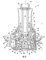
FIG. 4 is a right cross-sectional view of the sprayhead ofFIG. 1 . -
FIG. 5 is a top cross-sectional view of the sprayhead through line 5-5 ofFIG. 4 . -
FIG. 6 is a top cross-sectional view of the sprayhead through line 6-6 ofFIG. 4 . -
FIG. 7 is a top cross-sectional view of the sprayhead through line 7-7 ofFIG. 4 . -
FIG. 8 is a top cross-sectional view of the sprayhead through line 8-8 ofFIG. 4 . -
FIG. 9 is a top cross-sectional view of the sprayhead through line 9-9 ofFIG. 4 . -
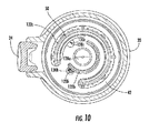
FIG. 10 is a top cross-sectional view of the sprayhead through line 10-10 ofFIG. 4 . -
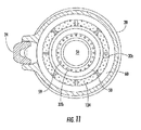
FIG. 11 is a top cross-sectional view of the sprayhead through line 11-11 ofFIG. 4 . -
FIG. 12 is a right elevation view of the sprayhead ofFIG. 1 having a bottom body portion removed. -
FIG. 13 is a front elevation view of the sprayhead ofFIG. 1 having a bottom body portion and actuator removed. -
FIG. 14 is a top view of components of the sprayhead ofFIG. 1 , according to an exemplary embodiment. -
FIG. 15 is a top view of components ofFIG. 14 in another position. -
FIG. 16 is a top view of components ofFIG. 14 in another position. -
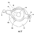
FIG. 17 is a top view of components ofFIG. 14 in another position. -
FIG. 18 is a top view of components ofFIG. 14 in another position. -
FIG. 19 is a front elevation view of the sprayhead ofFIG. 1 . -
FIG. 20 is a rear elevation view of the sprayhead ofFIG. 1 -
FIG. 21 is a top plan view of the sprayhead ofFIG. 1 -
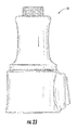
FIG. 22 is a bottom plan view of the sprayhead ofFIG. 1 . -
FIG. 23 is a left elevation view of the sprayhead ofFIG. 1 . - Referring generally to the FIGURES, a sprayhead and components thereof are shown according to an exemplary embodiment. The sprayhead includes a first disc and a second disc, which is movable relative to the first disc. When the second disc is moved in a first direction (e.g., translation, rotation, etc.) relative to the first disc, the volume of fluid flow through the sprayhead is controlled. When the second disc is moved in a second direction (e.g., rotation, translation, etc.) relative to the first disc, the function (e.g., spray pattern, spray pulsation, etc.) is controlled.
- To facilitate relative movement of the first and second discs, the first and second discs are located in a body having a first or upper body portion and a second or lower body portion. The first disc is fixed relative to the upper body portion, and the second disc is rotationally fixed relative to the lower body portion. Thus, relative rotation of the upper and lower body portions causes relative rotation of the first and second discs. An actuator coupling the body and the second disc may be used to cause translation of the second disc relative to the first disc.
- A conventional faucet sprayhead may include a valve which directs water between an aerated outlet and a non-aerated outlet. However, as faucet technology improves and specialized spray patterns may be used to more efficiently use water, there is a need for a valve which can distribute water to multiple functional outlets. According to various embodiments, the sprayhead has three or more possible functions. According to the exemplary embodiment shown, the sprayhead has three possible functions.
- Before discussing further details of the sprayhead and/or the components thereof, it should be noted that references to "front," "back," "rear," "upward," "downward," "inner," "outer," "right," and "left" in this description are merely used to identify the various elements as they are oriented in the FIGURES. These terms are not meant to limit the element which they describe, as the various elements may be oriented differently in various applications.
- It should further be noted that for purposes of this disclosure, the term "coupled" means the joining of two members directly or indirectly to one another. Such joining may be stationary in nature or movable in nature and/or such joining may allow for the flow of fluids, electricity, electrical signals, or other types of signals or communication between the two members. Such joining may be achieved with the two members or the two members and any additional intermediate members being integrally formed as a single unitary body with one another or with the two members or the two members and any additional intermediate members being attached to one another. Such joining may be permanent in nature or, alternatively, may be removable or releasable in nature.
- Letters in the reference numerals in the present disclosure are generally used to indicate a particular flow path to which the object of that reference numeral is associated. The objects of similarly numbered reference numerals may or may not have similar structure. For example,
outlets - Referring to
FIGS. 1-3 , asprayhead 10 is shown to extend axially along an axis "L" from a first or top orinlet end 12 to a second or bottom oroutlet end 14. Thesprayhead 10 includes abody 16 having a first orupper body portion 18 and a second orlower body portion 20 rotatably coupled to theupper body portion 18. Thesprayhead 10 is further shown to include aconnector 22 that is proximate theinlet end 12 and is configured to couple thesprayhead 10 to a faucet (not shown). Theconnector 22 defines aninlet 23 for receiving a fluid (e.g., water) into thesprayhead 10. According to an exemplary embodiment, theconnector 22 threadably couples to a hose extending through the spout of the faucet such that thesprayhead 10 is fluidly coupled to the faucet. The connection allows thesprayhead 10 to be decoupled from the faucet and the hose extracted from the spout, and allows the hose to be retracted into the spout and thesprayhead 10 to be coupled to the faucet. Thesprayhead 10 further includes an actuator (e.g., toggle, switch, etc.), shown asbutton 24, coupled to thelower body portion 20. According to the exemplary embodiment, thelower body portion 20 includes abutton housing portion 26 having one or more studs 28 (e.g., bosses, protrusions, axles, etc.) that extend through one or more openings 30 (seeFIG. 12 ) and allow thebutton 24 to pivot thereupon. Actuation of thebutton 24 causes a change in operation (e.g., volume control, function control, etc.) of thesprayhead 10, as will be described in more detail below with respect to the exemplary embodiment. - Referring to
FIG. 2 , fluid flows from theinlet 23 to one or more outlets (e.g.,first outlet 32a,second outlet 32b,third outlet 32c, etc.), generally referred to asoutlet 32, which are located proximate thebottom end 14. Each of theoutlets 32 may have the same or different functions. For example, according to the exemplary embodiment, thefirst outlet 32a provides an aerated stream of fluid from thesprayhead 10. Thesecond outlet 32b provides a spray of fluid through a plurality oforifices 34b to form a defined shaped spray pattern having a shaped spray arrangement having a focal length. As shown, theorifices 34b are oriented in various directions such that the streams of water exiting theorifices 34b form a wedge shape having a defined spray pattern in a focal region that is configured at a predetermined focal length from thesecond outlet 32b. An example of such an outlet is shown and described inU.S. Patent Application No. 13/359,089 , which is incorporated by reference herein in its entirety. Thethird outlet 32c provides another spray of fluid through a plurality oforifices 34c. As shown, theorifices 34c are arranged in a different pattern than theorifices 34b of thesecond outlet 32b. For example, theorifices 34c may provide substantially parallel streams or may provide an array of parallel and outward trajectory streams so as to provide a non-intersecting shower of streams of fluid. - It is contemplated that any of the
outlets 32 may have any of the features described above, or may have any other function of water. Further, theorifices orifices - Referring to
FIG. 4 , a cross-section ofsprayhead 10 is shown according to an exemplary embodiment. Acartridge 40 is received in thebody 16 and includes acartridge body 42 having a first or upper orinlet end 41 and a second or lower or outlet end 43 opposite the inlet end. Theoutlet end 43 of thecartridge body 42 includes an inner portion 44 configured to extend into anadapter 50, which supports anaerator 52. Theoutlet end 43 of thecartridge body 42 further includes an outer portion 46 havingthreads 48 which are configured to threadably couple to acartridge bottom 60. Thecartridge bottom 60 includes thethird outlet 32c and includes anannular ledge 62 configured to retain theadapter 50 within thecartridge 40. Anouter surface 64 of thecartridge bottom 60 may also provide a surface about or along which thelower body portion 20 of thesprayhead 10 may slide when rotated. - The
inlet end 41 of thecartridge body 42 is coupled to an annular collar 66 (e.g., cap, etc.), for example, viainternal threads 67. Thecollar 66 defines a bore 68 (e.g., opening, passageway, etc.), through which extends a tube 70 (e.g., conduit, hose, etc.). Thetube 70 is coupled to theconnector 22 and defines a channel or bore 72 that transports fluid from theinlet 23, through theupper body portion 18, to a third orinlet disc 74. Theinlet disc 74 defines a passageway or bore 76 extending axially through theinlet disc 74. Thebore 76 receives fluid from thebore 72 in thetube 70 and transports the fluid through theinlet disc 74. Theinlet disc 74 may be a ceramic disc, and according to the exemplary embodiment, is fixed relative to thetube 70. - Further referring to
FIGS. 5 and6 , a second or movable disc 80 (e.g., a ceramic disc, etc.) includes a second orinlet side 82 slidably coupled and adjacent to theinlet disc 74 and a first oroutlet side 84 opposite theinlet side 82. A bore 86 extends at least partially through themovable disc 80 from theinlet side 82 toward theoutlet side 84. According to the embodiment shown, thebore 86 extends axially completely through themovable disc 80. Achannel 88 extends radially along theoutlet side 84 from afirst end 90 fluidly coupled to thebore 86 to asecond end 92 opposite thefirst end 90. A first lateral end of themovable disc 80 couples to thebutton 24, which facilitates rotational and radial movement of themovable disc 80 relative to theinlet disc 74 and a first oroutlet disc 110. According the exemplary embodiment, the first lateral end of themovable disc 80 includes aball 94 which engages a socket located on thebutton 24. A second lateral end of themovable disc 80 includes an opening 96 (e.g., hole, passageway, bore, etc.) for receiving apin 98 that is fixed relative to thecartridge 40. As shown, thepin 98 is fixed to thecartridge body 42. Thepin 98 limits lateral or radial motion of themovable disc 80, thereby preventing accidental disassembly or excessive dislocation of themovable disc 80. Thepin 98 further limits rotational motion of themovable disc 80, thereby creating a pivot about whichmovable disc 80 rotates. - Referring briefly to
FIGS. 12 and13 , portions of thesprayhead 10 are shown according to an exemplary bodiment.FIG. 12 shows a right elevation view, andFIG. 13 shows a front elevation view, of thesprayhead 10 having thelower body portion 20 removed.Cartridge body 42 defines afront opening 100 and arear opening 102 which permit themovable disc 80 to translate and rotate therethrough. - Further referring to
FIGS. 7 and8 , theoutlet disc 110 is fixed relative to thecartridge 40 and includes a second or inlet side 112 adjacent to theoutlet side 84 of themovable disc 80. Theoutlet disc 110 and themovable disc 80 are slidably coupled at the interface of the inlet side 112 of the outlet disc and theoutlet side 84 of themovable disc 80 allowing relative movement therebetween (e.g., rotational, circumferential, lateral, radial, translational, etc.). Theoutlet disc 110 further includes a first or outlet side 114 opposite the inlet side 112. At least onetab 116 is received in aslot 118 defined by thecartridge body 42. The engagement of thetab 116 and theslot 118 fixes theoutlet disc 110 relative to thecartridge 40. - The
outlet disc 110 includes a plurality of outlet ports 120, shown as afirst outlet port 120a, which is fluidly coupled to thefirst outlet 32a; asecond outlet port 120b, which is fluidly coupled to thesecond outlet 32b; and athird outlet port 120c, which is fluidly coupled to thethird outlet 32c. As shown, the outlet ports 120 each have an oval shape on the inlet side 112 of theoutlet disc 110. As the outlet ports 120 pass or extend through theoutlet disc 110, the outlet ports 120 move towards, and change shape to interface with, a corresponding passageway in thecartridge body 42. For example, thefirst outlet port 120a extends inward towards a round opening proximate the center of theoutlet disc 110, thereby forming a substantially pear or key-shaped opening. The second andthird outlet ports outlet disc 110. According to other embodiments, the outlet ports 120 may have any of a variety of shapes, which may or may not be the same for all of the outlet ports 120. - Referring to
FIGS. 4 ,14 , and15 , during operation thesprayhead 10, actuation of thebutton 24 causes thebutton 24 to move themovable disc 80 in a lateral or radial direction relative to theoutlet disc 110. Applying an inward force to abottom portion 121 of thebutton 24 causes thebutton 24 to rotate about a pivot (e.g., studs 28) and causes anupper portion 123 of thebutton 24 to move outward. As theupper portion 123 of thebutton 24 moves outward, thebutton 24 pulls theball 94, which in turn pulls themovable disc 80 from a first position, shown for example inFIG. 14 , to a second position, shown for example inFIG. 15 . As themovable disc 80 moves from the first position to the second position, thechannel 88 passes over the at least one of the outlet ports 120 such that thechannel 88 progressively overlaps the at least one of the outlet ports 120. As thechannel 88 progressively overlaps the at least one of the outlet ports 120, the size of the passageway between thechannel 88 and the outlet port 120 increases, thereby permitting an increased volume of fluid to flow therethrough. - When an inward force is applied to the upper portion of the
button 24, the lateral force is transferred through theball 94 to move themovable disc 80 in the opposite direction as described above. As the movable disc moves from the second position towards the first position, thesecond end 92 of thechannel 88 passes over the at least one of the outlet ports 120 such that the overlap between thechannel 88 and the at least one of the outlet ports 120 progressively diminishes, thereby reducing the opening between thechannel 88 and the outlet ports 120, which in turn reduces the volume of fluid passing therethrough. Translation of themovable disc 80 between the first and second positions may be continuous, thus providing continuously variable control of the volume of fluid flow. For example,FIG. 18 shows themovable disc 18 in an intermediary position which allows a flow volume somewhere between minimum flow and maximum flow. Accordingly, motion of the movable disc in a first direction (e.g., radial, lateral, etc.) controls the volume of fluid flowing through thesprayhead 10. - Referring to
FIGS. 4 ,16 , and17 , rotating thelower body portion 20 of thesprayhead 10 relative to theupper body portion 18 causes thebutton housing portion 26 of thelower body portion 20 to apply a rotational or circumferential force on thebutton 24, thereby causing thebutton 24 to move rotationally or circumferentially. The rotational forces are transferred through theball 94 of themovable disc 80 and cause themovable disc 80 to rotate about thepin 98. Rotation of themovable disc 80 about thepin 98 changes the radial alignment of thechannel 88 relative to the outlet ports 120. For example, referring toFIG. 16 , counterclockwise rotation of themovable disc 80 causes thechannel 88 to align with theoutlet port 120b, which in turn causes any fluid flowing through thechannel 88 to pass into theoutlet port 120b and to subsequently exit the sprayhead through thesecond outlet 32b. Alternatively, referring toFIG. 17 , clockwise rotation of themovable disc 80 causes thechannel 88 to align with theoutlet ports 120c, which in turn causes any fluid flowing from thechannel 88 to enter theoutlet ports 120c and to subsequently exit thesprayhead 10 through thethird outlet 32c. - According to the embodiment shown, rotation of the
movable disc 80 is continuous so that thechannel 88 may be aligned with one of theoutlet ports outlet ports FIG. 18 ) oroutlet ports movable disc 80 may be in quantum increments. For example, detents may be used to align thechannel 88 with one of the outlet ports 120 at a time. - Referring to
FIG. 9 , thecartridge body 42 includes one or more grooves, generally referred to asgroove 122, formed in a surface or face 124 of thecartridge body 42. Theface 124 is adjacent to and couples to the outlet side 114 of theoutlet disc 110. The one ormore grooves 122 are configured to receive one or more seals, generally referred to asseal 126, which are located between thecartridge body 42 and theoutlet disc 110 and seal each fluid outlet path from one another. - Referring to
FIGS. 10 and11 , thecartridge body 42 includes a plurality of passageways 128, shown asfirst bore 128a,second bore 128b, andthird bore 128c, which transport fluid from theoutlet disc 110 toward therespective outlet - The
first bore 128a extends axially from theface 124, where it junctions with thefirst outlet port 120a, to a bottom end of thecartridge body 42, shown to be in the inner portion 44 thereof, where it fluidly couples with theinternal bore 54 of theadapter 50. Thesecond bore 128b extends axially downward from theface 124 where it junctions with thesecond outlet port 120b of theoutlet disc 110. According to the exemplary embodiment shown, anopening 130b is formed on an inner side of the bore wall such that thesecond bore 128b communicates with an annularinner chamber 132b, which allows the fluid to distribute circumferentially around thesprayhead 10. Thethird bore 128c extends axially downward from theface 124 where it junctions with thethird outlet port 120c of theoutlet disc 110. According to the exemplary embodiment shown, an opening 84c is formed on an outer side of the bore wall such that thethird bore 128c communicates with an annularouter chamber 132c, which allows the fluid passing therethrough to distribute circumferentially around thesprayhead 10. Theouter chamber 132c defines an opening at the bottom thereof, which empties into achamber 134 of thecartridge bottom 60, which provides fluid to thethird outlet 32c. Aseal 136 is retained between the inner portion 44 and theadapter 50 to prevent fluid fromouter chamber 132c from entering theadapter 50. - The
adapter 50 is located betweencartridge body 42 and thecartridge bottom 60. Theadapter 50 is shown to include aninner wall 56 and an outer wall 57 joined by a flange orweb 58, defines theorifices 34b of thesecond outlet 32b. Achamber 59 is defined between theinner wall 56 and the outer wall 57. Thechamber 59 is fluidly coupled to, and receives fluid from, theinner chamber 132b of thecartridge body 42. Fluid drains from thechamber 59 throughorifices 34b of thesecond outlet 32b. - The
inner wall 56 of theadapter 50 defines theinternal bore 54 which receives and supports theaerator 52. Fluid flowing to theaerator 52 exits thesprayhead 10 via thefirst outlet 32a. According to the exemplary embodiment shown, the outer wall 57 of theadapter 50 and the outer portion 46 of thecartridge body 42 define theouter chamber 132c. - The construction and arrangement of the elements of the sprayhead as shown in the exemplary embodiments are illustrative only. Although only a few embodiments of the present disclosure have been described in detail, those skilled in the art who review this disclosure will readily appreciate that many modifications are possible (e.g., variations in sizes, dimensions, structures, shapes and proportions of the various elements, values of parameters, mounting arrangements, use of materials, colors, orientations, etc.) without materially departing from the novel teachings and advantages of the subject matter recited. For example, elements shown as integrally formed may be constructed of multiple parts or elements. The elements and assemblies may be constructed from any of a wide variety of materials that provide sufficient strength or durability, in any of a wide variety of colors, textures, and combinations. Additionally, in the subject description, the word "exemplary" is used to mean serving as an example, instance, or illustration. Any embodiment or design described herein as "exemplary" is not necessarily to be construed as preferred or advantageous over other embodiments or designs. Rather, use of the word "exemplary" is intended to present concepts in a concrete manner. Accordingly, all such modifications are intended to be included within the scope of the present disclosure. Other substitutions, modifications, changes, and omissions may be made in the design, operating conditions, and arrangement of the preferred and other exemplary embodiments without departing from the scope of the appended claims.
- The order or sequence of any process or method steps may be varied or resequenced according to alternative embodiments. Any means-plus-function clause is intended to cover the structures described herein as performing the recited function and not only structural equivalents but also equivalent structures. Other substitutions, modifications, changes and omissions may be made in the design, operating configuration, and arrangement of the preferred and other exemplary embodiments without departing from the scope of the appended claims.
Claims (15)
- A fluid control valve, comprising:a first disc including:a first outlet port coupled to a first outlet;a second outlet port coupled to a second outlet; anda third outlet port coupled to a third outlet;a fluid inlet; anda second disc slidably coupled to the first disc and movable relative thereto, the second disc located between the fluid inlet and the first disc;wherein movement in a first direction of the second disc relative to the first disc fluidly couples the fluid inlet to at least one of the first outlet port, the second outlet port, and the third outlet port, and wherein movement in a second direction of the second disc relative to the first disc controls a volume of fluid flowing from through the fluid control valve.
- The fluid control valve of claim 1, wherein the second disc comprises:a first side adjacent the first disc;a second side opposite the first side;wherein the second disc defines a bore fluidly coupled to the fluid inlet and extending from the second side at least partially through the second disc; andwherein the second disc defines a channel extending radially along the first side, the channel having a first end fluidly coupled to the bore.
- The fluid control valve of claim 2, wherein when the second disc moves in the first direction relative to the first disc, the channel radially aligns with at least one of the first outlet port, the second outlet port, and the third outlet port.
- The fluid control valve of any of claims 2-3, wherein the channel includes a second end opposite the first end, and wherein when the second disc moves in the second direction relative to the first disc, the second end passes over the at least one of the outlet ports such that the channel progressively overlaps the at least one of the outlet ports.
- The fluid control valve of claim 4, wherein when the second disc moves in a direction opposite the second direction relative to the first disc, the second end passes over the at least one of the outlet ports such that the overlap between the channel and the at least one of the outlet ports progressively diminishes.
- The fluid control valve of any of claims 1-5, wherein the first outlet, the second outlet, and the third outlet provide different spray patterns for fluid exiting the respective fluid outlet.
- A sprayhead including the fluid control valve of any of claims 1-6, comprising a cartridge fixed relative to the first disc.
- The sprayhead of claim 7, comprising a body having a first portion and a second portion rotatably coupled to the first portion;
wherein the second portion is coupled to the second disc; and
wherein the first portion is interconnected with the cartridge such that the first portion and the first disc rotate together relative to the second disc. - The sprayhead of claim 8, wherein rotation of the first portion relative to the second portion selectively couples the fluid inlet to at least one of the first outlet port, the second outlet port, and the third outlet port.
- The sprayhead of any of claims 8-9, further comprising a button coupled to the second disc such that actuation of the button causes the second disc to move in the second direction relative to the first disc.
- The sprayhead of claim 10, wherein the button is pivotally coupled to the second portion of the body.
- The sprayhead of any of claims 7-11, wherein the cartridge comprises a cartridge bottom supporting an adapter and defining the third outlet.
- The sprayhead of claim 12, comprising the adapter, wherein the adapter supports an aerator fluidly coupled to the first outlet port and defines the second outlet.
- The fluid control valve of any of claims 1-13, wherein the first direction is a rotational direction.
- The fluid control valve of any of claims 1-14, wherein the second direction is a radial direction.
Applications Claiming Priority (1)
| Application Number | Priority Date | Filing Date | Title |
|---|---|---|---|
| US201361748940P | 2013-01-04 | 2013-01-04 |
Publications (1)
| Publication Number | Publication Date |
|---|---|
| EP2752249A1 true EP2752249A1 (en) | 2014-07-09 |
Family
ID=49920135
Family Applications (1)
| Application Number | Title | Priority Date | Filing Date |
|---|---|---|---|
| EP14150082.7A Withdrawn EP2752249A1 (en) | 2013-01-04 | 2014-01-02 | Fluid control valve and sprayhead with such a valve |
Country Status (3)
| Country | Link |
|---|---|
| US (3) | US9259747B2 (en) |
| EP (1) | EP2752249A1 (en) |
| CN (1) | CN103909025B (en) |
Families Citing this family (7)
| Publication number | Priority date | Publication date | Assignee | Title |
|---|---|---|---|---|
| US9259747B2 (en) * | 2013-01-04 | 2016-02-16 | Kohler Co. | Multi-function sprayhead |
| US9757740B2 (en) | 2014-11-19 | 2017-09-12 | Kohler Co. | Multi-function sprayhead |
| CN106861946A (en) * | 2015-12-10 | 2017-06-20 | 厦门松霖科技有限公司 | A kind of top-spraying gondola of back toggle switching |
| US10150122B2 (en) * | 2016-11-10 | 2018-12-11 | Xiamen Lota International Co., Ltd. | Shower head structure |
| US11406992B2 (en) | 2016-11-10 | 2022-08-09 | Xiamen Lota International Co., Ltd. | Shower head fixture |
| US12006671B2 (en) | 2018-12-11 | 2024-06-11 | Fortune Brands Water Innovations LLC | Wand with boost and mode selections |
| CN112974003B (en) * | 2021-04-09 | 2023-02-03 | 厦门欧圣斯卫浴有限公司 | A spray gun and a fixed seat matching the spray gun |
Citations (4)
| Publication number | Priority date | Publication date | Assignee | Title |
|---|---|---|---|---|
| DE2843666A1 (en) * | 1978-10-06 | 1980-04-17 | Rokal Armaturen Gmbh | Hand shower with changeover valve - has two ceramic control discs, one movable against fixed disc |
| WO1994007065A1 (en) * | 1992-09-16 | 1994-03-31 | Gevipi A.G. | A cartridge with plates of hard material for a single-control faucet |
| US20080156902A1 (en) * | 2006-12-29 | 2008-07-03 | Water Pik, Inc. | Handheld showerhead with mode control and method of selecting a handheld showerhead mode |
| CN201651426U (en) * | 2010-04-19 | 2010-11-24 | 厦门松霖科技有限公司 | A multi-stage control waterway device |
Family Cites Families (50)
| Publication number | Priority date | Publication date | Assignee | Title |
|---|---|---|---|---|
| US3346148A (en) | 1965-01-04 | 1967-10-10 | Harry Swartz | Dispensing shower head |
| US3739983A (en) | 1970-01-22 | 1973-06-19 | Woog Inst Rech | Multi-jet spray nozzle with a movable shutter member |
| DE3419208A1 (en) * | 1984-05-23 | 1985-11-28 | Hans Grohe Gmbh & Co Kg, 7622 Schiltach | CONTROL INSERT FOR SANITARY MIXING FITTINGS |
| US4717074A (en) * | 1984-06-25 | 1988-01-05 | Wagner Spray Tech Corporation | Adjustable orifice for a sprayer unit |
| CN1004829B (en) * | 1985-05-23 | 1989-07-19 | 汉斯格罗(有限无限)股份两合公司 | Control core for sanitary mixer valves |
| US4765540A (en) | 1985-11-21 | 1988-08-23 | Fluidyne Corporation | Process and apparatus for generating multiple fluid jets |
| US4651770A (en) | 1986-03-28 | 1987-03-24 | Speakman Company | Ceramic disc faucet valve |
| US4794952A (en) | 1987-02-04 | 1989-01-03 | American Standard | Combination mixing valve and appliance valve assembly |
| CA1319080C (en) | 1988-12-20 | 1993-06-15 | Pietro Rollini | Valve assembly for plumbing fixture |
| DE3903999A1 (en) * | 1989-02-10 | 1990-08-16 | Grohe Armaturen Friedrich | SANITARY MIXING VALVE |
| DE4118540A1 (en) | 1991-06-06 | 1992-12-10 | Walter Gruber | Hand-held shower for personal hygiene - has additional water outlet ring, for soft jet, with extra operating position |
| US5397064A (en) | 1993-10-21 | 1995-03-14 | Heitzman; Charles J. | Shower head with variable flow rate, pulsation and spray pattern |
| CA2155433A1 (en) | 1993-12-24 | 1995-07-06 | Arita Kinya | Washing water injection machine and dish washing device provided with said washing water injection machine |
| DE19509661C2 (en) | 1995-03-17 | 1999-02-04 | Hansa Metallwerke Ag | Multi-function hand shower |
| CA2223355A1 (en) | 1996-12-04 | 1998-06-04 | Interbath, Inc. | Inner/outer spray ring |
| US5806771A (en) | 1997-01-21 | 1998-09-15 | Moen Incorporated | Kitchen faucet side spray |
| US5918811A (en) * | 1997-06-12 | 1999-07-06 | Speakman Company | Showerhead with variable spray patterns and internal shutoff valve |
| US6367710B2 (en) * | 1998-12-03 | 2002-04-09 | Chen-Yueh Fan | Showerhead |
| IT1309070B1 (en) | 1999-02-10 | 2002-01-16 | Patrizia Bollo | CARTRIDGE WITH CERAMIC DISCS FOR THE MIXING OF FLUIDS IN SIMILAR TAPS. |
| US6607148B1 (en) | 2000-01-13 | 2003-08-19 | Kohler Co. | Shower head |
| JP3637277B2 (en) | 2000-03-21 | 2005-04-13 | 大塚化学ホールディングス株式会社 | Flame retardant, flame retardant resin composition, molded product, and electronic component |
| US6634380B2 (en) * | 2000-10-30 | 2003-10-21 | Access Business Group International Llc | Ceramic disc diverter valve |
| US6959731B2 (en) | 2000-10-30 | 2005-11-01 | Access Business Group International Llc | Ceramic disc diverter valve |
| JP3746692B2 (en) | 2001-07-31 | 2006-02-15 | 治 三宅 | Handheld sprayer for bathroom |
| NZ525880A (en) | 2003-05-14 | 2005-11-25 | Methven Ltd | Method and apparatus for producing droplet spray |
| US7070125B2 (en) | 2003-05-16 | 2006-07-04 | Newfrey Llc | Multi-pattern pull-out spray head |
| EP1799355A1 (en) | 2004-08-13 | 2007-06-27 | Joseph H. Clearman | Spray apparatus and dispensing tubes therefore |
| US7322535B2 (en) | 2005-01-24 | 2008-01-29 | Newfrey, Llc | Faucet spray head |
| US7487797B2 (en) | 2005-01-26 | 2009-02-10 | David Di Nunzio | 4 port fluid cartridge |
| US7373950B2 (en) | 2005-02-09 | 2008-05-20 | Ching Yu Huang | Ceramic control valve |
| US7871020B2 (en) | 2006-01-26 | 2011-01-18 | Masco Corporation Of Indiana | Faucet spray head with volume control |
| EP2007483A2 (en) | 2006-04-20 | 2008-12-31 | Water Pik, Inc. | Converging spray showerhead |
| US7494074B2 (en) | 2006-05-01 | 2009-02-24 | Newfrey Llc | Faucet sprayhead with mode and volume controls |
| US7331536B1 (en) | 2006-07-14 | 2008-02-19 | Globe Union Industrial Corp. (Guic) | Shower head |
| US7753074B2 (en) | 2006-07-28 | 2010-07-13 | Masco Corporation Of Indiana | Mixing valve |
| US7909269B2 (en) | 2006-09-19 | 2011-03-22 | Kohler Co. | Faucet spray control assembly |
| US7344094B1 (en) | 2006-10-05 | 2008-03-18 | Martin Tracy | Flexible neck faucet sprayer |
| CN200960483Y (en) | 2006-10-25 | 2007-10-17 | 厦门建霖工业有限公司 | Faucet spray gun |
| US8104697B2 (en) | 2008-03-19 | 2012-01-31 | Petrovic John E | Fluid spray control device |
| US7762479B2 (en) | 2008-03-27 | 2010-07-27 | Xiamen Lota International Co., Ltd. | Adjustable showerhead with ceramic disk assembly |
| HUP0800431A2 (en) | 2008-07-14 | 2010-04-28 | Kerox Ipari Es Kereskedelmi Kf | Single-lever mixing faucet operated by turning |
| US8376248B2 (en) | 2008-11-25 | 2013-02-19 | As Ip Holdco, L.L.C. | Faucet having pull-out spray handle |
| JP4623329B2 (en) | 2008-12-17 | 2011-02-02 | Toto株式会社 | Shower equipment |
| US9220376B2 (en) | 2008-12-17 | 2015-12-29 | Toto Ltd. | Shower apparatus |
| US8733674B2 (en) | 2009-04-30 | 2014-05-27 | Kohler Co. | Body spray nozzle |
| US8113442B2 (en) | 2009-07-31 | 2012-02-14 | Xiamen Solex High-Tech Industries Co., Ltd. | Hand held shower with a button switching mechanism for switching spray patterns |
| US20110147477A1 (en) | 2009-12-18 | 2011-06-23 | Hoi Kwan Henry Mang | Fluid diversifying apparatus and method |
| JP5505700B2 (en) | 2010-02-18 | 2014-05-28 | Toto株式会社 | Shower equipment |
| JP5534416B2 (en) | 2010-02-18 | 2014-07-02 | Toto株式会社 | Shower equipment |
| US9259747B2 (en) * | 2013-01-04 | 2016-02-16 | Kohler Co. | Multi-function sprayhead |
-
2013
- 2013-12-30 US US14/143,884 patent/US9259747B2/en active Active
-
2014
- 2014-01-02 EP EP14150082.7A patent/EP2752249A1/en not_active Withdrawn
- 2014-01-03 CN CN201410003599.4A patent/CN103909025B/en not_active Expired - Fee Related
-
2015
- 2015-05-05 US US14/704,374 patent/US9649645B2/en active Active
-
2016
- 2016-12-29 US US15/393,801 patent/US10086390B2/en active Active
Patent Citations (4)
| Publication number | Priority date | Publication date | Assignee | Title |
|---|---|---|---|---|
| DE2843666A1 (en) * | 1978-10-06 | 1980-04-17 | Rokal Armaturen Gmbh | Hand shower with changeover valve - has two ceramic control discs, one movable against fixed disc |
| WO1994007065A1 (en) * | 1992-09-16 | 1994-03-31 | Gevipi A.G. | A cartridge with plates of hard material for a single-control faucet |
| US20080156902A1 (en) * | 2006-12-29 | 2008-07-03 | Water Pik, Inc. | Handheld showerhead with mode control and method of selecting a handheld showerhead mode |
| CN201651426U (en) * | 2010-04-19 | 2010-11-24 | 厦门松霖科技有限公司 | A multi-stage control waterway device |
Also Published As
| Publication number | Publication date |
|---|---|
| CN103909025A (en) | 2014-07-09 |
| US10086390B2 (en) | 2018-10-02 |
| US9259747B2 (en) | 2016-02-16 |
| CN103909025B (en) | 2016-09-21 |
| US20140191064A1 (en) | 2014-07-10 |
| US9649645B2 (en) | 2017-05-16 |
| US20170106381A1 (en) | 2017-04-20 |
| US20150231651A1 (en) | 2015-08-20 |
Similar Documents
| Publication | Publication Date | Title |
|---|---|---|
| US10086390B2 (en) | Multi-function sprayhead | |
| US20260054276A1 (en) | Multi-function sprayhead | |
| US20240075484A1 (en) | Spray head | |
| CN110280412B (en) | bathtub faucet | |
| CN1787856B (en) | Pull-out nozzles with multiple water outlets | |
| EP3792410B1 (en) | Water outlet device | |
| US20120012676A1 (en) | Handheld water discharging device | |
| US20170183847A1 (en) | Sink spout | |
| CA2979011C (en) | Variable dual flow fitting | |
| CN113117909A (en) | Water outlet device and kitchen shower head | |
| JP5260583B2 (en) | Water discharge device and assembly method thereof | |
| KR20180003628U (en) | shower faucet with assembly shutter and waterway | |
| US20200032498A1 (en) | Nozzle assembly | |
| JP6733129B2 (en) | Water discharge device | |
| KR101323625B1 (en) | faucet having outlet apparatus change ability | |
| CN212284500U (en) | Water outlet device and kitchen shower head | |
| CN210846849U (en) | Bathtub tap | |
| JP6591219B2 (en) | Spout unit | |
| CN112568761A (en) | Shower bath | |
| US20250214093A1 (en) | Multifunctional spray head assembly | |
| CN213762379U (en) | Water diversion assembly and top shower | |
| JP2005226409A (en) | Water discharging device in faucet facility | |
| KR102889981B1 (en) | Functional shower having mist discharging function | |
| JP5106469B2 (en) | Water discharge device in faucet equipment | |
| CA2708454A1 (en) | Handheld water discharging device |
Legal Events
| Date | Code | Title | Description |
|---|---|---|---|
| 17P | Request for examination filed |
Effective date: 20140102 |
|
| AK | Designated contracting states |
Kind code of ref document: A1 Designated state(s): AL AT BE BG CH CY CZ DE DK EE ES FI FR GB GR HR HU IE IS IT LI LT LU LV MC MK MT NL NO PL PT RO RS SE SI SK SM TR |
|
| AX | Request for extension of the european patent |
Extension state: BA ME |
|
| PUAI | Public reference made under article 153(3) epc to a published international application that has entered the european phase |
Free format text: ORIGINAL CODE: 0009012 |
|
| STAA | Information on the status of an ep patent application or granted ep patent |
Free format text: STATUS: THE APPLICATION IS DEEMED TO BE WITHDRAWN |
|
| 18D | Application deemed to be withdrawn |
Effective date: 20150110 |