EP2752181A2 - Tablet cartridge for medication dispensing apparatus - Google Patents
Tablet cartridge for medication dispensing apparatus Download PDFInfo
- Publication number
- EP2752181A2 EP2752181A2 EP13176104.1A EP13176104A EP2752181A2 EP 2752181 A2 EP2752181 A2 EP 2752181A2 EP 13176104 A EP13176104 A EP 13176104A EP 2752181 A2 EP2752181 A2 EP 2752181A2
- Authority
- EP
- European Patent Office
- Prior art keywords
- tablet
- stopper
- extension ends
- rotor
- grooves
- Prior art date
- Legal status (The legal status is an assumption and is not a legal conclusion. Google has not performed a legal analysis and makes no representation as to the accuracy of the status listed.)
- Granted
Links
Images

Classifications
-
- B—PERFORMING OPERATIONS; TRANSPORTING
- B65—CONVEYING; PACKING; STORING; HANDLING THIN OR FILAMENTARY MATERIAL
- B65D—CONTAINERS FOR STORAGE OR TRANSPORT OF ARTICLES OR MATERIALS, e.g. BAGS, BARRELS, BOTTLES, BOXES, CANS, CARTONS, CRATES, DRUMS, JARS, TANKS, HOPPERS, FORWARDING CONTAINERS; ACCESSORIES, CLOSURES, OR FITTINGS THEREFOR; PACKAGING ELEMENTS; PACKAGES
- B65D83/00—Containers or packages with special means for dispensing contents
- B65D83/04—Containers or packages with special means for dispensing contents for dispensing annular, disc-shaped, or spherical or like small articles, e.g. tablets or pills
-
- A—HUMAN NECESSITIES
- A61—MEDICAL OR VETERINARY SCIENCE; HYGIENE
- A61J—CONTAINERS SPECIALLY ADAPTED FOR MEDICAL OR PHARMACEUTICAL PURPOSES; DEVICES OR METHODS SPECIALLY ADAPTED FOR BRINGING PHARMACEUTICAL PRODUCTS INTO PARTICULAR PHYSICAL OR ADMINISTERING FORMS; DEVICES FOR ADMINISTERING FOOD OR MEDICINES ORALLY; BABY COMFORTERS; DEVICES FOR RECEIVING SPITTLE
- A61J3/00—Devices or methods specially adapted for bringing pharmaceutical products into particular physical or administering forms
-
- A—HUMAN NECESSITIES
- A61—MEDICAL OR VETERINARY SCIENCE; HYGIENE
- A61J—CONTAINERS SPECIALLY ADAPTED FOR MEDICAL OR PHARMACEUTICAL PURPOSES; DEVICES OR METHODS SPECIALLY ADAPTED FOR BRINGING PHARMACEUTICAL PRODUCTS INTO PARTICULAR PHYSICAL OR ADMINISTERING FORMS; DEVICES FOR ADMINISTERING FOOD OR MEDICINES ORALLY; BABY COMFORTERS; DEVICES FOR RECEIVING SPITTLE
- A61J7/00—Devices for administering medicines orally, e.g. spoons; Pill counting devices; Arrangements for time indication or reminder for taking medicine
- A61J7/0076—Medicament distribution means
- A61J7/0084—Medicament distribution means for multiple medicaments
-
- B—PERFORMING OPERATIONS; TRANSPORTING
- B65—CONVEYING; PACKING; STORING; HANDLING THIN OR FILAMENTARY MATERIAL
- B65B—MACHINES, APPARATUS OR DEVICES FOR, OR METHODS OF, PACKAGING ARTICLES OR MATERIALS; UNPACKING
- B65B1/00—Packaging fluent solid material, e.g. powders, granular or loose fibrous material, loose masses of small articles, in individual containers or receptacles, e.g. bags, sacks, boxes, cartons, cans, or jars
- B65B1/30—Devices or methods for controlling or determining the quantity or quality or the material fed or filled
-
- G—PHYSICS
- G07—CHECKING-DEVICES
- G07F—COIN-FREED OR LIKE APPARATUS
- G07F17/00—Coin-freed apparatus for hiring articles; Coin-freed facilities or services
- G07F17/0092—Coin-freed apparatus for hiring articles; Coin-freed facilities or services for assembling and dispensing of pharmaceutical articles
Landscapes
- Health & Medical Sciences (AREA)
- Life Sciences & Earth Sciences (AREA)
- Animal Behavior & Ethology (AREA)
- General Health & Medical Sciences (AREA)
- Public Health (AREA)
- Veterinary Medicine (AREA)
- Engineering & Computer Science (AREA)
- Mechanical Engineering (AREA)
- General Physics & Mathematics (AREA)
- Physics & Mathematics (AREA)
- Quality & Reliability (AREA)
- Chemical & Material Sciences (AREA)
- Medicinal Chemistry (AREA)
- Pharmacology & Pharmacy (AREA)
- Medical Preparation Storing Or Oral Administration Devices (AREA)
- Basic Packing Technique (AREA)
Abstract
Description
- This application claims priority from and the benefit of Korean Patent Application No.
10-2013-0000309, filed on January 2, 2013 - The following description relates to a tablet cartridge for use in a medication dispensing apparatus to hold tablets or capsules.
- Recently, many studies on an automated medication dispensing apparatus have been carried out to overcome problems caused by pharmacists' manual dispensing of medications. Generally, a medication dispensing apparatus has a set of tablet cartridges arranged in multiple layers with upper part to contain various types of tablets or capsules held in an upper chamber. The tablets contained in the tablet cartridges may be selectively discharged under the user's control by use of a computer interfaced with the tablet cartridges. The tablets discharged from the cartridges are collected in a hopper and then packaged in a packaging unit located in a lower part of the medication dispensing apparatus.
- The tablet cartridge has an opening for dispensing tablets at a lower part of a case, and a cylindrical rotor above the dispensing opening with a plurality of "guide-teeth" and tablet insertion grooves along its circumference. The rotor is connected to a rotator placed under the dispensing opening. The rotor rotates along with the rotator, which is rotated by a rotation motor.
- A large number of tablets are contained in the case of the tablet cartridge, and a single tablet or a predetermined number of tablets are stored in each tablet insertion groove between the guide-teeth of the rotor disposed below the case. In this state, as the rotor rotates, the tablet insertion grooves change positions and each is sequentially brought into line with the dispensing opening, such that the tablets in the
tablet insertion groove 112 are discharged through the dispensing opening. At this time, a tablet stopper is provided at the top of the dispensing opening. The tablet stopper closes the top of the tablet insertion groove that is placed in line with the dispensing opening, so as to prevent other tablets contained in another tablet insertion groove from being discharged through the dispensing opening. - According to conventional methods, an installation of a tablet stopper in a case is difficult to perform. To address this problem, Korean Utility Model Registration No.
20-0438560 (published on February 22, 2008 - If the type of tablets to be contained in the case changes, a rotor needs to be replaced by another one having a width and height suitable for the changed tablets. According to the related art, an insertion hole has to be altered in accordance with the width and height of tablet insertion grooves of the new rotor, so as to allow the tablet separation plate to be inserted through the case, and thus difficulties in efficiently adapting to the rotor replacement occur.
- In one general aspect, there is provided a tablet cartridge for use in a medication dispensing apparatus, the tablet cartridge including: a rotor configured to have a plurality of guide-teeth protruding at regular intervals along a circumference of the rotor, and have tablet insertion grooves formed between the guide-teeth; a tablet stopper disposed to close a top of one of the tablet insertion grooves; a case configured to include a container to accommodate the tablets, a rotor housing portion at a lower part of the container to house the rotor, a dispensing opening formed at a position on a lower portion of the rotor accommodating portion, corresponding to a position of the tablet stopper, and a stopper insertion hole of a length that allows for the tablet stopper to adjust its height while being inserted into the stopper insertion hole; and a stopper cover coupled to the case to close the stopper insertion groove, and have the tablet stopper mounted thereon at an adjusted height.
- Other features will become apparent to those skilled in the art from the following detailed description, which, taken in conjunction with the attached drawings, discloses exemplary embodiments of the invention.
-
-
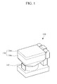
FIG. 1 is a diagram illustrating a perspective view of a tablet cartridge for use in a medication dispensing apparatus. -
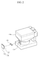
FIG. 2 is a diagram illustrating an exploded perspective view of a stopper cover and tablet stopper separated from the tablet cartridge ofFIG. 1 . -
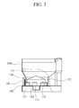
FIG. 3 is a diagram illustrating a frontal cross-sectional view ofFIG. 1 . -
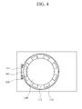
FIG. 4 is a diagram illustrating a top cross-sectional view ofFIG. 1 . -
FIG. 5 is a diagram illustrating an exploded perspective view ofFIG. 2 to describe procedures of mounting a tablet stopper to a height adjustment unit. -
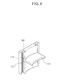
FIG. 6 is a diagram illustrating a perspective view of the tablet stopper mounted on the height adjustment unit ofFIG. 5 . -
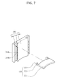
FIG. 7 is a diagram illustrating an exploded perspective view ofFIG. 2 to describe procedures of mounting a tablet stopper to another height adjustment unit. - The following detailed description is provided to assist the reader in gaining a comprehensive understanding of the methods, apparatuses and/or systems described herein. Accordingly, various changes, modifications, and equivalents of the systems, apparatuses and/or methods described herein will be suggested to those of ordinary skill in the art. Also, descriptions of well-known functions and constructions are omitted to increase clarity and conciseness.
-
FIG. 1 is a diagram illustrating a perspective view of a tablet cartridge for use in a medication dispensing apparatus.FIG. 2 is a diagram illustrating an exploded perspective view of a stopper cover and tablet stopper separated from the tablet cartridge ofFIG. 1 .FIG. 3 is a diagram illustrating a frontal cross-sectional view ofFIG. 1 .FIG. 4 is a diagram illustrating a top cross-sectional view ofFIG. 1 . - Referring to
FIGS. 1 to 4 , thetablet cartridge 100 may be used in a medication dispensing apparatus to contain tablets or capsules, and may include arotor 110, atablet stopper 120, acase 130, and astopper cover 140. - The
rotor 110 may have a plurality of guide-teeth 111 protruding at regular intervals along a circumference of therotor 110, and havetablet insertion grooves 112 formed between the guide-teeth 111. The width and height of eachtable insertion groove 112 may be determined dynamically to conform to the shape of the tablets or capsules contained in thecase 130. When the type of tablets to be contained in thecase 130 is changed, therotor 110 may be replaced by another rotor having tablet insertion grooves with a width and height suitable for the changed tablets. Therotor 110 may be connected with a rotator (not shown) at a lower part thereof. Therotor 110 rotates along with the rotator which is driven by a motor, such as a rotation motor. The rotator and the rotation motor may be provided in a cartridge base mounted on a lower portion of thecase 130. - The
tablet stopper 120 may be disposed to close a top of any one of thetablet insertion grooves 112. A portion of the tablet stopper 120 that covers the top of thetablet insertion groove 112 may be larger than the top opening of thetablet insertion groove 112. Thetablet stopper 120 may be designed to adapt to virtually all widths of thetablet insertion grooves 112, which may vary depending on the types of tablets. - The
case 130 may include acontainer 131 to accommodate the tablets. Thecase 130 may include arotor housing portion 132 at a lower part of thecontainer 131 to house the rotor 10. Thecase 130 may have a dispensingopening 133 formed at a position on a lower portion of therotor accommodating portion 132, corresponding to a position of thetablet stopper 120. - The
case 130 may include acase body 130a and acase cover 130b. Thecase body 130a includes thecontainer 131, therotor housing portion 132, and the dispensing opening 133. Thecase body 130a is configured to have an open top allowing the tablets to be contained therethrough. Thecase cover 130b is hinged to a top edge of thecase body 130a in such a manner to open and close the open top of thecase body 130a. - A large number of tablets may be contained in the
container 131 of thecase 130, and a single tablet or a predetermined number of tablets may be stored in eachtablet insertion groove 112 of therotor 110. As therotor 110 rotates, thetablet insertion grooves 112 change positions and each is sequentially brought into line with the dispensingopening 133, such that the tablets in thetablet insertion groove 112 are discharged through the dispensing opening 113. In this state, the tablet stopper 120 closes the open top of thetablet insertion groove 112 placed in a line with the dispensingopening 133, and hence only the tablets contained in thetablet insertion groove 112 in the position can be discharged through the dispensingopening 133. - The
case body 130a of thecase 130 has a stopper insertion hole 134 of a length that allows for thetablet stopper 120 to adjust its height while being inserted in the stopper insertion hole 134. Thestopper cover 140 is attached to thecase 130 to close the stopper insertion hole 134, and thetablet stopper 120 is mounted on thestopper cover 140 at an adjusted height. - As such, even when the height of the
tablet insertion grooves 112 changes as the types of tablets to be contained in thecase 130 are changed, the height of thetablet stopper 120 is able to be adjusted within the stopper insertion hole 134 to correspond to the changed height of thetablet insertion grooves 112. Thetablet stopper 120 is coupled to the stopper cover at the adjusted height. Therefore, it is possible to flexibly and conveniently deal with the replacement of therotor 110 for changes in the type of tablet. - Meanwhile, the
tablet stopper 120 may include astopper body 121, first extension ends 122, and second extension ends. Thestopper body 121 may have a size large enough to close the top of onetablet insertion groove 112. The first extension ends 122 extend from each side of thestopper body 122 toward thestopper cover 140. The second extension ends 123 are bent inward and extend from the respective first extension ends 122. The first extension ends 122 and the second extension ends 123 may be coupled to form an "L" shape. Thetablet stopper 120 may be made of an elastic material, such that the first extension ends 122 can be spread apart by external forces and then restored to their original positions when the external force is removed. For example, thetablet stopper 120 may be made of a material, such as plastic, rubber, and the like, which has elasticity. - The
stopper cover 140 may include acover body 141 and aheight adjustment portion 142. Thecover body 141 is coupled with thecase 130 to close and open the stopper insertion hole 134. Theheight adjustment portion 142 is formed along an inner surface of thecover body 141, guides the height adjustment of the first and second extension ends 122 and 123, and secures the first and second extension ends 122 and 123. - For example, as shown in
FIGS. 5 and6 , theheight adjustment portion 142 may include a mounting block 143, cutportions 144, andrail grooves 145. The mounting block 143 may protrude from the inner surface of thecover body 141. - The
cut portions 144 have pieces 143a vertically arranged along both sides of the mounting block 143. The pieces 143a can be cut away from thecut portions 144. Whenpieces 144a at positions corresponding to an adjusted height of the first extension ends 122 to be coupled to thestopper cover 140 are cut away, securinggrooves 144b remain at the parts from which the pieces are removed. The first extension ends 122 are inserted and fixed in the respective securinggrooves 144b. Therail grooves 145 are provided to both sides of the mounting block 143 to guide the movement of the second extension ends 123 inserted therein. - The
tablet stopper 120 may be coupled to thestopper cover 140 as follows. Thepieces 144a at positions corresponding to the height of the first extension ends 122 to be coupled to thestopper cover 140 are cut away from thecut portions 144. The first extension ends 122 are placed at positions corresponding to the securinggrooves 144b, and the second extension ends 123 are, then, inserted in therespective rail grooves 145 while the first extension ends 122 are spread apart by external force. When the external force applied to the first extension ends 122 is removed, the first extension ends 122 are restored to their original positions, and thereby result in being inserted into the securinggrooves 144b. As such, thetablet stopper 120 is coupled to thestopper cover 140 at the adjusted height. - As another example, as shown in
FIG. 7 , aheight adjustment portion 242 may include securingunits 244, instead of thecut portions 144. The securingunits 244 may include fixingprojections 244a arranged vertically on both sides of the mounting block 143 at regular intervals from one another. Securinggrooves 244b may be formed between every twoadjacent fixing projections 244a. The first extension ends 122 may be inserted and fixed in the securinggrooves 244b at positions corresponding to an adjusted height of the first extension ends 122. Accordingly, it is possible to mount thetablet stopper 120 to the stopper cover at the adjusted height. - According to the exemplary embodiments of the present invention, when a type of tablets to be accommodated in a case of a tablet cartridge changes and a rotor is replaced by another rotor having tablet insertion grooves with a width and height suitable for the changed tablet, it is possible to adaptably mount the tablet stopper to the case and thereby to flexibly and conveniently deal with the replacement of the rotor.
- It will be apparent to those skilled in the art that various modifications and variations can be made in the present invention without departing from the spirit or scope of the invention. Thus, it is intended that the present invention covers the modifications and variations of this invention provided they come within the scope of the appended claims and their equivalents.
- A number of exemplary embodiments have been described above. Nevertheless, it will be understood that various modifications may be made. For example, suitable results may be achieved if the described techniques are performed in a different order and/or if components in a described system, architecture, device, or circuit are combined in a different manner and/or replaced or supplemented by other components or their equivalents. Accordingly, other implementations are within the scope of the following claims.
Claims (5)
- A tablet cartridge for use in a medication dispensing apparatus, the tablet cartridge comprising:a rotor configured to have a plurality of guide-teeth protruding at regular intervals along a circumference of the rotor, and have tablet insertion grooves formed between the guide-teeth;a tablet stopper disposed to close a top of one of the tablet insertion grooves;a case configured to include a container to accommodate the tablets, a rotor housing portion at a lower part of the container to house the rotor, a dispensing opening formed at a position on a lower portion of the rotor accommodating portion, corresponding to a position of the tablet stopper, and a stopper insertion hole of a length that allows for the tablet stopper to adjust its height while being inserted into the stopper insertion hole; anda stopper cover coupled to the case to close the stopper insertion groove, and have the tablet stopper mounted thereon at an adjusted height.
- The tablet cartridge of claim 1, wherein the tablet stopper comprises a stopper body to close the top of one of the tablet insertion grooves, first extension ends extending from each side of the stopper body toward the stopper cover and second extension ends bent inwardly and extending from the respective first extension ends.
- The tablet cartridge of claim 2, wherein the stopper cover comprises a cover body coupled with the case to close and open the stopper insertion hole and a height adjustment portion formed along an inner surface of the cover body to guide height adjustment of the first and second extension ends and secure the first and second extension ends.
- The tablet cartridge of claim 3, wherein the height adjustment unit comprises a mounting block protruding from the inner surface of the cover body, cut-portions having pieces vertically arranged along both sides of the mounting block and having the first extension ends inserted and fixed in securing grooves which are formed by removing pieces at positions corresponding to a height of the first extension ends from the respective cut-portions, and rail grooves provided to both sides of the mounting block to guide movement of the second extension ends inserted in the rail grooves.
- The tablet cartridge of claim 3, wherein the height adjustment unit comprises a mounting block protruding from the inner surface of the cover body, a securing unit having fixing projections arranged vertically on both sides of the mounting block at regular intervals and securing grooves formed between every adjacent two of the fixing projections and having the first extension ends inserted and fixed in the securing grooves at positions responding to an adjusted height of the first extension ends, and rail grooves formed on both sides of the mounting block to guide the movement of the second extension ends while being inserted therein.
Applications Claiming Priority (1)
| Application Number | Priority Date | Filing Date | Title |
|---|---|---|---|
| KR1020130000309A KR101449717B1 (en) | 2013-01-02 | 2013-01-02 | Tablets cartridge for drug dispensing apparatus |
Publications (3)
| Publication Number | Publication Date |
|---|---|
| EP2752181A2 true EP2752181A2 (en) | 2014-07-09 |
| EP2752181A3 EP2752181A3 (en) | 2015-01-21 |
| EP2752181B1 EP2752181B1 (en) | 2016-09-14 |
Family
ID=48783015
Family Applications (1)
| Application Number | Title | Priority Date | Filing Date |
|---|---|---|---|
| EP13176104.1A Not-in-force EP2752181B1 (en) | 2013-01-02 | 2013-07-11 | Tablet cartridge for medication dispensing apparatus |
Country Status (4)
| Country | Link |
|---|---|
| US (1) | US9181017B2 (en) |
| EP (1) | EP2752181B1 (en) |
| KR (1) | KR101449717B1 (en) |
| CN (1) | CN103910143B (en) |
Cited By (4)
| Publication number | Priority date | Publication date | Assignee | Title |
|---|---|---|---|---|
| EP2804156A1 (en) * | 2013-05-14 | 2014-11-19 | Infopia Co., Ltd. | Pill cartridge for medication packaging apparatus |
| EP3389022A1 (en) * | 2017-04-11 | 2018-10-17 | Becton Dickinson Rowa Germany GmbH | Storage container for a storage and dispensing station |
| CN108697582A (en) * | 2016-01-29 | 2018-10-23 | 贝克顿迪金森罗瓦德国有限公司 | Storage container for drug gas holder station |
| EP3492062A4 (en) * | 2016-07-27 | 2020-03-18 | Tosho, Inc. | Tablet cassette for tablet feeder |
Families Citing this family (16)
| Publication number | Priority date | Publication date | Assignee | Title |
|---|---|---|---|---|
| EP2756834B1 (en) | 2011-01-14 | 2020-08-12 | Yuyama Mfg. Co., Ltd. | Tablet cassette |
| JP5957747B2 (en) * | 2011-02-01 | 2016-07-27 | 株式会社タカゾノテクノロジー | Tablet cassette |
| JP6000195B2 (en) * | 2013-07-03 | 2016-09-28 | 株式会社トーショー | Tablet cassette |
| JP6384835B2 (en) * | 2015-02-05 | 2018-09-05 | 株式会社トーショー | Tablet cassette |
| US10583979B2 (en) * | 2015-10-12 | 2020-03-10 | Carefusion Germany 326 Gmbh | Storage container for drug dispensing and storage stations |
| US10028888B2 (en) * | 2016-01-29 | 2018-07-24 | Carefusion Germany 326 Gmbh | Storage container for a storage and delivery station for drugs |
| TWI724134B (en) * | 2016-03-25 | 2021-04-11 | 日商湯山製作所有限公司 | Rotor for tablet box and tablet box |
| US10380824B2 (en) | 2017-02-03 | 2019-08-13 | Becton Dickinson Rowa Germany Gmbh | Storage and dispensing station for blister packaging machine |
| EP4044136A1 (en) * | 2017-02-03 | 2022-08-17 | Becton Dickinson Rowa Germany GmbH | Storage and dispensing station for a blister packaging machine |
| AU201712821S (en) * | 2017-02-16 | 2017-05-26 | Canister Solutions B V | Canister for dispensing of medication in tablet form. |
| AU201712819S (en) * | 2017-02-16 | 2017-05-25 | Canister Solutions B V | Canister for dispensing of medication in tablet form. |
| CA3072585A1 (en) * | 2017-08-15 | 2019-02-21 | Yuyama Mfg. Co., Ltd. | Tablet guiding path adjusting apparatus for tablet cassette |
| AU2019225527B2 (en) | 2018-02-21 | 2024-04-04 | Tosho,Inc. | Tablet cassette |
| EP3616675B1 (en) * | 2018-08-31 | 2021-04-14 | Becton Dickinson Rowa Germany GmbH | Storage container for a storage and dispensing station for medicaments |
| CN109606956A (en) * | 2018-11-12 | 2019-04-12 | 吕永美 | A kind of medication dispensing device |
| EP3711869B1 (en) * | 2019-03-21 | 2021-06-02 | Harro Höfliger Verpackungsmaschinen GmbH | Sorting device for tablets |
Citations (1)
| Publication number | Priority date | Publication date | Assignee | Title |
|---|---|---|---|---|
| KR200438560Y1 (en) | 2007-02-15 | 2008-02-22 | 김호연 | Setting structure of tablet separator of tablet cassette for automatic tablet sorting and counting machine |
Family Cites Families (12)
| Publication number | Priority date | Publication date | Assignee | Title |
|---|---|---|---|---|
| JP3519835B2 (en) * | 1995-09-05 | 2004-04-19 | 三洋電機株式会社 | Solid preparation filling device |
| SK18562001A3 (en) | 1999-06-21 | 2002-05-09 | Sara Lee/De N. V. | Dosing device adapted for dispensing a concentrate from a holder in a metered manner |
| JP2002153541A (en) * | 2000-11-20 | 2002-05-28 | Tosho Inc | Medicine feeder |
| US6497342B2 (en) * | 2000-11-30 | 2002-12-24 | Mckesson Automated Healthcare, Inc. | Medicine feeder |
| JP4553505B2 (en) * | 2001-03-16 | 2010-09-29 | 株式会社トーショー | Dispensing system |
| DK1704844T3 (en) | 2004-01-05 | 2017-11-13 | Tosho Inc | AUTOMATIC ADMINISTRATOR AND PHARMACEUTICAL SUPPLY |
| JP4398759B2 (en) * | 2004-03-03 | 2010-01-13 | 株式会社トーショー | Drug feeder and assembly thereof |
| KR100800290B1 (en) * | 2006-11-01 | 2008-02-01 | (주)제이브이엠 | Cassette device for an automatic medicine packing machine |
| KR100716751B1 (en) | 2006-12-13 | 2007-05-14 | 하이팜텍주식회사 | Tablet dispenser |
| EP3064190B1 (en) | 2008-09-18 | 2018-11-21 | Yuyama Mfg. Co., Ltd. | Tablet feeder |
| CN102905979B (en) * | 2010-05-17 | 2015-05-20 | 株式会社汤山制作所 | Tablet cassette |
| JP5957747B2 (en) * | 2011-02-01 | 2016-07-27 | 株式会社タカゾノテクノロジー | Tablet cassette |
-
2013
- 2013-01-02 KR KR1020130000309A patent/KR101449717B1/en active IP Right Grant
- 2013-07-11 EP EP13176104.1A patent/EP2752181B1/en not_active Not-in-force
- 2013-07-23 US US13/948,597 patent/US9181017B2/en not_active Expired - Fee Related
- 2013-08-06 CN CN201310339463.6A patent/CN103910143B/en not_active Expired - Fee Related
Patent Citations (1)
| Publication number | Priority date | Publication date | Assignee | Title |
|---|---|---|---|---|
| KR200438560Y1 (en) | 2007-02-15 | 2008-02-22 | 김호연 | Setting structure of tablet separator of tablet cassette for automatic tablet sorting and counting machine |
Cited By (9)
| Publication number | Priority date | Publication date | Assignee | Title |
|---|---|---|---|---|
| EP2804156A1 (en) * | 2013-05-14 | 2014-11-19 | Infopia Co., Ltd. | Pill cartridge for medication packaging apparatus |
| US20140339252A1 (en) * | 2013-05-14 | 2014-11-20 | Infopia Co., Ltd. | Pill cartridge for medication packaging apparatus |
| CN108697582A (en) * | 2016-01-29 | 2018-10-23 | 贝克顿迪金森罗瓦德国有限公司 | Storage container for drug gas holder station |
| JP2019503235A (en) * | 2016-01-29 | 2019-02-07 | ベクトン・ディッキンソン・ロワ・ジャーマニー・ゲーエムベーハー | Storage container for storage and delivery station for medicines |
| EP3492062A4 (en) * | 2016-07-27 | 2020-03-18 | Tosho, Inc. | Tablet cassette for tablet feeder |
| EP3389022A1 (en) * | 2017-04-11 | 2018-10-17 | Becton Dickinson Rowa Germany GmbH | Storage container for a storage and dispensing station |
| WO2018188837A1 (en) * | 2017-04-11 | 2018-10-18 | Becton Dickinson Rowa Germany Gmbh | Storage container for a storage and dispensing station |
| US11383866B2 (en) | 2017-04-11 | 2022-07-12 | Becton Dickinson Rowa Germany Gmbh | Storage container for a storage and dispensing station |
| US11661222B2 (en) | 2017-04-11 | 2023-05-30 | Becton Dickinson Rowa Germany Gmbh | Storage container for a storage and dispensing station |
Also Published As
| Publication number | Publication date |
|---|---|
| KR20140092505A (en) | 2014-07-24 |
| EP2752181A3 (en) | 2015-01-21 |
| KR101449717B1 (en) | 2014-10-15 |
| CN103910143B (en) | 2016-06-01 |
| CN103910143A (en) | 2014-07-09 |
| US9181017B2 (en) | 2015-11-10 |
| US20140183208A1 (en) | 2014-07-03 |
| EP2752181B1 (en) | 2016-09-14 |
Similar Documents
| Publication | Publication Date | Title |
|---|---|---|
| EP2752181B1 (en) | Tablet cartridge for medication dispensing apparatus | |
| EP2804156A1 (en) | Pill cartridge for medication packaging apparatus | |
| CN102341307B (en) | Powder removing device for tablet feeder | |
| CN108628411B (en) | Cabinet | |
| WO2012070883A2 (en) | Tablet medicine cassette for device for wrapping medicine | |
| CN101134534A (en) | Card dispensing apparatus | |
| TW201308780A (en) | Connector | |
| WO2004083069A1 (en) | Improvements in or relating to blister packaging | |
| JP7022146B2 (en) | Storage container for storage / distribution station | |
| CN109982524A (en) | Box and stop device | |
| CN101920602A (en) | Printer | |
| EP3257781A1 (en) | Supply cartridge, beverage preparation machine and process of operation of a machine using said supply cartridge | |
| EP2656830A1 (en) | Automatic medicine packaging apparatus | |
| CN110861838A (en) | Buffering packing device | |
| KR101496652B1 (en) | variable cartridge for drug dispensing apparatus | |
| US6788550B1 (en) | Circuit card retention device | |
| JP2006272248A (en) | Device for inserting to erect microtube | |
| KR20110132168A (en) | Cup dispenser | |
| US10232375B2 (en) | Support device for a sample material container for centrifugation | |
| US7475783B2 (en) | Dispenser for holding a means for holding a plurality of units for dispensing, and a method for operating the dispenser | |
| CN210284945U (en) | Packing box (Chinese character' jiangsu | |
| US20220274757A1 (en) | Touchless package | |
| JP2017207858A (en) | Cap member and device equipped with cap member | |
| CN108137175B (en) | Storage container for a storage and dispensing station for pharmaceutical products | |
| EP3257780A1 (en) | Supply cartridge with binary code, beverage preparation machine and process for operation of a machine using said supply cartridge |
Legal Events
| Date | Code | Title | Description |
|---|---|---|---|
| 17P | Request for examination filed |
Effective date: 20130711 |
|
| AK | Designated contracting states |
Kind code of ref document: A2 Designated state(s): AL AT BE BG CH CY CZ DE DK EE ES FI FR GB GR HR HU IE IS IT LI LT LU LV MC MK MT NL NO PL PT RO RS SE SI SK SM TR |
|
| AX | Request for extension of the european patent |
Extension state: BA ME |
|
| PUAI | Public reference made under article 153(3) epc to a published international application that has entered the european phase |
Free format text: ORIGINAL CODE: 0009012 |
|
| PUAL | Search report despatched |
Free format text: ORIGINAL CODE: 0009013 |
|
| AK | Designated contracting states |
Kind code of ref document: A3 Designated state(s): AL AT BE BG CH CY CZ DE DK EE ES FI FR GB GR HR HU IE IS IT LI LT LU LV MC MK MT NL NO PL PT RO RS SE SI SK SM TR |
|
| AX | Request for extension of the european patent |
Extension state: BA ME |
|
| RIC1 | Information provided on ipc code assigned before grant |
Ipc: G07F 17/00 20060101ALI20141212BHEP Ipc: B65D 83/04 20060101ALI20141212BHEP Ipc: G07F 11/44 20060101ALI20141212BHEP Ipc: A61J 7/00 20060101AFI20141212BHEP |
|
| 17Q | First examination report despatched |
Effective date: 20150129 |
|
| GRAP | Despatch of communication of intention to grant a patent |
Free format text: ORIGINAL CODE: EPIDOSNIGR1 |
|
| INTG | Intention to grant announced |
Effective date: 20160204 |
|
| RAP1 | Party data changed (applicant data changed or rights of an application transferred) |
Owner name: LCK CO., LTD. Owner name: JILIN PROVINCE LONGCHUANG MEDICAL TREATMENT TECHNO |
|
| GRAS | Grant fee paid |
Free format text: ORIGINAL CODE: EPIDOSNIGR3 |
|
| GRAA | (expected) grant |
Free format text: ORIGINAL CODE: 0009210 |
|
| AK | Designated contracting states |
Kind code of ref document: B1 Designated state(s): AL AT BE BG CH CY CZ DE DK EE ES FI FR GB GR HR HU IE IS IT LI LT LU LV MC MK MT NL NO PL PT RO RS SE SI SK SM TR |
|
| REG | Reference to a national code |
Ref country code: GB Ref legal event code: FG4D |
|
| REG | Reference to a national code |
Ref country code: CH Ref legal event code: EP |
|
| REG | Reference to a national code |
Ref country code: IE Ref legal event code: FG4D |
|
| REG | Reference to a national code |
Ref country code: AT Ref legal event code: REF Ref document number: 828119 Country of ref document: AT Kind code of ref document: T Effective date: 20161015 |
|
| REG | Reference to a national code |
Ref country code: DE Ref legal event code: R096 Ref document number: 602013011378 Country of ref document: DE |
|
| REG | Reference to a national code |
Ref country code: LT Ref legal event code: MG4D |
|
| REG | Reference to a national code |
Ref country code: NL Ref legal event code: MP Effective date: 20160914 |
|
| PG25 | Lapsed in a contracting state [announced via postgrant information from national office to epo] |
Ref country code: RS Free format text: LAPSE BECAUSE OF FAILURE TO SUBMIT A TRANSLATION OF THE DESCRIPTION OR TO PAY THE FEE WITHIN THE PRESCRIBED TIME-LIMIT Effective date: 20160914 Ref country code: NO Free format text: LAPSE BECAUSE OF FAILURE TO SUBMIT A TRANSLATION OF THE DESCRIPTION OR TO PAY THE FEE WITHIN THE PRESCRIBED TIME-LIMIT Effective date: 20161214 Ref country code: LT Free format text: LAPSE BECAUSE OF FAILURE TO SUBMIT A TRANSLATION OF THE DESCRIPTION OR TO PAY THE FEE WITHIN THE PRESCRIBED TIME-LIMIT Effective date: 20160914 Ref country code: HR Free format text: LAPSE BECAUSE OF FAILURE TO SUBMIT A TRANSLATION OF THE DESCRIPTION OR TO PAY THE FEE WITHIN THE PRESCRIBED TIME-LIMIT Effective date: 20160914 Ref country code: FI Free format text: LAPSE BECAUSE OF FAILURE TO SUBMIT A TRANSLATION OF THE DESCRIPTION OR TO PAY THE FEE WITHIN THE PRESCRIBED TIME-LIMIT Effective date: 20160914 |
|
| REG | Reference to a national code |
Ref country code: AT Ref legal event code: MK05 Ref document number: 828119 Country of ref document: AT Kind code of ref document: T Effective date: 20160914 |
|
| PG25 | Lapsed in a contracting state [announced via postgrant information from national office to epo] |
Ref country code: SE Free format text: LAPSE BECAUSE OF FAILURE TO SUBMIT A TRANSLATION OF THE DESCRIPTION OR TO PAY THE FEE WITHIN THE PRESCRIBED TIME-LIMIT Effective date: 20160914 Ref country code: NL Free format text: LAPSE BECAUSE OF FAILURE TO SUBMIT A TRANSLATION OF THE DESCRIPTION OR TO PAY THE FEE WITHIN THE PRESCRIBED TIME-LIMIT Effective date: 20160914 Ref country code: GR Free format text: LAPSE BECAUSE OF FAILURE TO SUBMIT A TRANSLATION OF THE DESCRIPTION OR TO PAY THE FEE WITHIN THE PRESCRIBED TIME-LIMIT Effective date: 20161215 Ref country code: LV Free format text: LAPSE BECAUSE OF FAILURE TO SUBMIT A TRANSLATION OF THE DESCRIPTION OR TO PAY THE FEE WITHIN THE PRESCRIBED TIME-LIMIT Effective date: 20160914 |
|
| PG25 | Lapsed in a contracting state [announced via postgrant information from national office to epo] |
Ref country code: RO Free format text: LAPSE BECAUSE OF FAILURE TO SUBMIT A TRANSLATION OF THE DESCRIPTION OR TO PAY THE FEE WITHIN THE PRESCRIBED TIME-LIMIT Effective date: 20160914 Ref country code: EE Free format text: LAPSE BECAUSE OF FAILURE TO SUBMIT A TRANSLATION OF THE DESCRIPTION OR TO PAY THE FEE WITHIN THE PRESCRIBED TIME-LIMIT Effective date: 20160914 |
|
| PG25 | Lapsed in a contracting state [announced via postgrant information from national office to epo] |
Ref country code: BE Free format text: LAPSE BECAUSE OF FAILURE TO SUBMIT A TRANSLATION OF THE DESCRIPTION OR TO PAY THE FEE WITHIN THE PRESCRIBED TIME-LIMIT Effective date: 20160914 Ref country code: BG Free format text: LAPSE BECAUSE OF FAILURE TO SUBMIT A TRANSLATION OF THE DESCRIPTION OR TO PAY THE FEE WITHIN THE PRESCRIBED TIME-LIMIT Effective date: 20161214 Ref country code: ES Free format text: LAPSE BECAUSE OF FAILURE TO SUBMIT A TRANSLATION OF THE DESCRIPTION OR TO PAY THE FEE WITHIN THE PRESCRIBED TIME-LIMIT Effective date: 20160914 Ref country code: PL Free format text: LAPSE BECAUSE OF FAILURE TO SUBMIT A TRANSLATION OF THE DESCRIPTION OR TO PAY THE FEE WITHIN THE PRESCRIBED TIME-LIMIT Effective date: 20160914 Ref country code: CZ Free format text: LAPSE BECAUSE OF FAILURE TO SUBMIT A TRANSLATION OF THE DESCRIPTION OR TO PAY THE FEE WITHIN THE PRESCRIBED TIME-LIMIT Effective date: 20160914 Ref country code: IS Free format text: LAPSE BECAUSE OF FAILURE TO SUBMIT A TRANSLATION OF THE DESCRIPTION OR TO PAY THE FEE WITHIN THE PRESCRIBED TIME-LIMIT Effective date: 20170114 Ref country code: PT Free format text: LAPSE BECAUSE OF FAILURE TO SUBMIT A TRANSLATION OF THE DESCRIPTION OR TO PAY THE FEE WITHIN THE PRESCRIBED TIME-LIMIT Effective date: 20170116 Ref country code: SK Free format text: LAPSE BECAUSE OF FAILURE TO SUBMIT A TRANSLATION OF THE DESCRIPTION OR TO PAY THE FEE WITHIN THE PRESCRIBED TIME-LIMIT Effective date: 20160914 Ref country code: AT Free format text: LAPSE BECAUSE OF FAILURE TO SUBMIT A TRANSLATION OF THE DESCRIPTION OR TO PAY THE FEE WITHIN THE PRESCRIBED TIME-LIMIT Effective date: 20160914 Ref country code: SM Free format text: LAPSE BECAUSE OF FAILURE TO SUBMIT A TRANSLATION OF THE DESCRIPTION OR TO PAY THE FEE WITHIN THE PRESCRIBED TIME-LIMIT Effective date: 20160914 |
|
| REG | Reference to a national code |
Ref country code: DE Ref legal event code: R097 Ref document number: 602013011378 Country of ref document: DE |
|
| PG25 | Lapsed in a contracting state [announced via postgrant information from national office to epo] |
Ref country code: IT Free format text: LAPSE BECAUSE OF FAILURE TO SUBMIT A TRANSLATION OF THE DESCRIPTION OR TO PAY THE FEE WITHIN THE PRESCRIBED TIME-LIMIT Effective date: 20160914 |
|
| PLBE | No opposition filed within time limit |
Free format text: ORIGINAL CODE: 0009261 |
|
| STAA | Information on the status of an ep patent application or granted ep patent |
Free format text: STATUS: NO OPPOSITION FILED WITHIN TIME LIMIT |
|
| REG | Reference to a national code |
Ref country code: FR Ref legal event code: PLFP Year of fee payment: 5 |
|
| PG25 | Lapsed in a contracting state [announced via postgrant information from national office to epo] |
Ref country code: DK Free format text: LAPSE BECAUSE OF FAILURE TO SUBMIT A TRANSLATION OF THE DESCRIPTION OR TO PAY THE FEE WITHIN THE PRESCRIBED TIME-LIMIT Effective date: 20160914 |
|
| 26N | No opposition filed |
Effective date: 20170615 |
|
| PG25 | Lapsed in a contracting state [announced via postgrant information from national office to epo] |
Ref country code: SI Free format text: LAPSE BECAUSE OF FAILURE TO SUBMIT A TRANSLATION OF THE DESCRIPTION OR TO PAY THE FEE WITHIN THE PRESCRIBED TIME-LIMIT Effective date: 20160914 |
|
| REG | Reference to a national code |
Ref country code: CH Ref legal event code: PL |
|
| GBPC | Gb: european patent ceased through non-payment of renewal fee |
Effective date: 20170711 |
|
| REG | Reference to a national code |
Ref country code: IE Ref legal event code: MM4A |
|
| PG25 | Lapsed in a contracting state [announced via postgrant information from national office to epo] |
Ref country code: IE Free format text: LAPSE BECAUSE OF NON-PAYMENT OF DUE FEES Effective date: 20170711 Ref country code: LI Free format text: LAPSE BECAUSE OF NON-PAYMENT OF DUE FEES Effective date: 20170731 Ref country code: GB Free format text: LAPSE BECAUSE OF NON-PAYMENT OF DUE FEES Effective date: 20170711 Ref country code: CH Free format text: LAPSE BECAUSE OF NON-PAYMENT OF DUE FEES Effective date: 20170731 |
|
| PG25 | Lapsed in a contracting state [announced via postgrant information from national office to epo] |
Ref country code: LU Free format text: LAPSE BECAUSE OF NON-PAYMENT OF DUE FEES Effective date: 20170711 |
|
| REG | Reference to a national code |
Ref country code: FR Ref legal event code: PLFP Year of fee payment: 6 |
|
| PG25 | Lapsed in a contracting state [announced via postgrant information from national office to epo] |
Ref country code: MT Free format text: LAPSE BECAUSE OF NON-PAYMENT OF DUE FEES Effective date: 20170711 |
|
| PG25 | Lapsed in a contracting state [announced via postgrant information from national office to epo] |
Ref country code: AL Free format text: LAPSE BECAUSE OF FAILURE TO SUBMIT A TRANSLATION OF THE DESCRIPTION OR TO PAY THE FEE WITHIN THE PRESCRIBED TIME-LIMIT Effective date: 20160914 |
|
| PGFP | Annual fee paid to national office [announced via postgrant information from national office to epo] |
Ref country code: DE Payment date: 20180730 Year of fee payment: 6 Ref country code: FR Payment date: 20180730 Year of fee payment: 6 |
|
| PG25 | Lapsed in a contracting state [announced via postgrant information from national office to epo] |
Ref country code: HU Free format text: LAPSE BECAUSE OF FAILURE TO SUBMIT A TRANSLATION OF THE DESCRIPTION OR TO PAY THE FEE WITHIN THE PRESCRIBED TIME-LIMIT; INVALID AB INITIO Effective date: 20130711 Ref country code: MC Free format text: LAPSE BECAUSE OF FAILURE TO SUBMIT A TRANSLATION OF THE DESCRIPTION OR TO PAY THE FEE WITHIN THE PRESCRIBED TIME-LIMIT Effective date: 20160914 |
|
| PG25 | Lapsed in a contracting state [announced via postgrant information from national office to epo] |
Ref country code: CY Free format text: LAPSE BECAUSE OF NON-PAYMENT OF DUE FEES Effective date: 20160914 |
|
| PG25 | Lapsed in a contracting state [announced via postgrant information from national office to epo] |
Ref country code: MK Free format text: LAPSE BECAUSE OF FAILURE TO SUBMIT A TRANSLATION OF THE DESCRIPTION OR TO PAY THE FEE WITHIN THE PRESCRIBED TIME-LIMIT Effective date: 20160914 |
|
| REG | Reference to a national code |
Ref country code: DE Ref legal event code: R119 Ref document number: 602013011378 Country of ref document: DE |
|
| PG25 | Lapsed in a contracting state [announced via postgrant information from national office to epo] |
Ref country code: TR Free format text: LAPSE BECAUSE OF FAILURE TO SUBMIT A TRANSLATION OF THE DESCRIPTION OR TO PAY THE FEE WITHIN THE PRESCRIBED TIME-LIMIT Effective date: 20160914 |
|
| PG25 | Lapsed in a contracting state [announced via postgrant information from national office to epo] |
Ref country code: DE Free format text: LAPSE BECAUSE OF NON-PAYMENT OF DUE FEES Effective date: 20200201 |
|
| PG25 | Lapsed in a contracting state [announced via postgrant information from national office to epo] |
Ref country code: FR Free format text: LAPSE BECAUSE OF NON-PAYMENT OF DUE FEES Effective date: 20190731 |