EP2752170A1 - Multi valve anti-reflux prosthesis - Google Patents
Multi valve anti-reflux prosthesis Download PDFInfo
- Publication number
- EP2752170A1 EP2752170A1 EP14150223.7A EP14150223A EP2752170A1 EP 2752170 A1 EP2752170 A1 EP 2752170A1 EP 14150223 A EP14150223 A EP 14150223A EP 2752170 A1 EP2752170 A1 EP 2752170A1
- Authority
- EP
- European Patent Office
- Prior art keywords
- valve
- prosthesis
- distal end
- distal
- pressure
- Prior art date
- Legal status (The legal status is an assumption and is not a legal conclusion. Google has not performed a legal analysis and makes no representation as to the accuracy of the status listed.)
- Granted
Links
Images





Classifications
-
- A—HUMAN NECESSITIES
- A61—MEDICAL OR VETERINARY SCIENCE; HYGIENE
- A61F—FILTERS IMPLANTABLE INTO BLOOD VESSELS; PROSTHESES; DEVICES PROVIDING PATENCY TO, OR PREVENTING COLLAPSING OF, TUBULAR STRUCTURES OF THE BODY, e.g. STENTS; ORTHOPAEDIC, NURSING OR CONTRACEPTIVE DEVICES; FOMENTATION; TREATMENT OR PROTECTION OF EYES OR EARS; BANDAGES, DRESSINGS OR ABSORBENT PADS; FIRST-AID KITS
- A61F2/00—Filters implantable into blood vessels; Prostheses, i.e. artificial substitutes or replacements for parts of the body; Appliances for connecting them with the body; Devices providing patency to, or preventing collapsing of, tubular structures of the body, e.g. stents
- A61F2/02—Prostheses implantable into the body
- A61F2/04—Hollow or tubular parts of organs, e.g. bladders, tracheae, bronchi or bile ducts
-
- A—HUMAN NECESSITIES
- A61—MEDICAL OR VETERINARY SCIENCE; HYGIENE
- A61F—FILTERS IMPLANTABLE INTO BLOOD VESSELS; PROSTHESES; DEVICES PROVIDING PATENCY TO, OR PREVENTING COLLAPSING OF, TUBULAR STRUCTURES OF THE BODY, e.g. STENTS; ORTHOPAEDIC, NURSING OR CONTRACEPTIVE DEVICES; FOMENTATION; TREATMENT OR PROTECTION OF EYES OR EARS; BANDAGES, DRESSINGS OR ABSORBENT PADS; FIRST-AID KITS
- A61F2/00—Filters implantable into blood vessels; Prostheses, i.e. artificial substitutes or replacements for parts of the body; Appliances for connecting them with the body; Devices providing patency to, or preventing collapsing of, tubular structures of the body, e.g. stents
- A61F2/02—Prostheses implantable into the body
- A61F2/24—Heart valves ; Vascular valves, e.g. venous valves; Heart implants, e.g. passive devices for improving the function of the native valve or the heart muscle; Transmyocardial revascularisation [TMR] devices; Valves implantable in the body
- A61F2/2475—Venous valves
-
- A—HUMAN NECESSITIES
- A61—MEDICAL OR VETERINARY SCIENCE; HYGIENE
- A61F—FILTERS IMPLANTABLE INTO BLOOD VESSELS; PROSTHESES; DEVICES PROVIDING PATENCY TO, OR PREVENTING COLLAPSING OF, TUBULAR STRUCTURES OF THE BODY, e.g. STENTS; ORTHOPAEDIC, NURSING OR CONTRACEPTIVE DEVICES; FOMENTATION; TREATMENT OR PROTECTION OF EYES OR EARS; BANDAGES, DRESSINGS OR ABSORBENT PADS; FIRST-AID KITS
- A61F2/00—Filters implantable into blood vessels; Prostheses, i.e. artificial substitutes or replacements for parts of the body; Appliances for connecting them with the body; Devices providing patency to, or preventing collapsing of, tubular structures of the body, e.g. stents
- A61F2/02—Prostheses implantable into the body
- A61F2/04—Hollow or tubular parts of organs, e.g. bladders, tracheae, bronchi or bile ducts
- A61F2002/044—Oesophagi or esophagi or gullets
Definitions
- the present invention relates to medical devices and in particular to a prosthesis having multiple valves for regulating fluid flow therethrough.
- the lower esophageal sphincter (LES) in healthy individuals allows food to pass into the stomach, but prevents gastric fluids from moving into the esophagus except when the patient vomits.
- Aspiration and gastroesophageal reflux disease (GERD) are clinical risks for patients having a malfunctioning LES or for patients having stents placed across the LES so that the LES remains open.
- Aspiration occurs when the stomach contents travel from the stomach into the lungs.
- Aspiration in the lungs can lead to pneumonia or death.
- GERD produces heartburn, abdominal pain and regurgitation of the stomach contents into the esophagus and pharynx.
- GERD may lead to the alteration of the lining of the esophagus that results in Barrett's Esophagus and may progress to esophageal cancer. Risk of aspiration and GERD in patients having a compromised LES increases when the patient is in a prone position.
- Anti-reflux esophageal prostheses or stents have been developed to treat tumors or strictures in the vicinity of the LES.
- An anti-reflux esophageal prosthesis or stent is typically placed in the lower esophagus and through the LES to maintain the patency thereof due to the presence of a cancerous tumor commonly found in the vicinity thereof or to treat benign tumor conditions, such as blockage or strictures.
- a problem with an esophageal prosthesis or stent is that fluid from the stomach flows into the mouth of the patient when in a prone position, increasing the risk of aspiration and reflux.
- a number of esophageal prostheses or stents utilize a one-way valve in which only food or fluid from the esophagus flows into the stomach in only an antegrade or forward direction.
- these one-way anti-reflux prostheses or stents present another problem.
- the patient wants to belch or vomit the patient is prevented from doing so, because the one-way valve prevents backward flow in the retrograde direction.
- Such a condition is not only painful to the patient, but can also lead to more complicated medical conditions.
- Other inverting valves can invert with pressure at which the patient coughs or belches that allows some reflux, however, these designs do not readily revert back to the original position.
- a prosthesis for controlling flow through a bodily lumen includes a body having a proximal portion, a distal portion and a lumen extending therethrough.
- the prosthesis also includes a first valve and a second valve operably connected to the body.
- the first valve has a proximal portion, a distal portion, a distal end extending distally relative to the proximal portion of the body and a lumen extending through the first valve.
- the first valve is closed in the absence of a second pressure and a third pressure that are greater than a first pressure.
- the second valve has a proximal portion, a distal portion, a distal end extending distally relative to a proximal portion of the body and a lumen extending through the second valve, the distal end of the first valve extending distal to the distal end of the second valve.
- the second valve and the first valve control flow through the prosthesis.
- proximal and distal should be understood as being in the terms of a physician delivering the prosthesis to a patient.
- distal means the portion of the prosthesis that is farthest from the physician and the term “proximal” means the portion of the prosthesis that is nearest to the physician.
- the present invention relates to medical devices, and in particular to prosthetic devices for implantation in a body lumen such as the lower esophageal sphincter or a vessel.
- implantable refers to an ability of a medical device to be positioned at a location within a body, such as within a body lumen, either temporarily, semi-permanently, or permanently. Permanent fixation of the device in a particular position is not required.
- implantation and “implanted” refer to the positioning of a medical device at a location within a body, such as within a body lumen.
- FIG. 1A illustrates a prosthesis 10 in accordance with an embodiment of the present invention.
- the prosthesis 10 includes a body 12 having proximal portion 14, a distal portion 16 and a lumen 18 extending therethrough.
- the body 12 may be an expandable stent, such as a self-expanding stent.
- expandable stents include the Z-Stent ® and the EVOLUTION ® stent (Cook Medical, Inc., Bloomington, IN).
- the body 12 may be a non-expandable tubular stent.
- the proximal portion 14 may include an end portion 15 having an expanded outer diameter and the distal portion 16 may include an end portion 17 having an expanded outer diameter.
- the body 12 may include a coating or a sleeve 22 extending through or around the body 12 that is liquid impermeable so that liquid and nutrients flowing from the proximal portion 14 to the distal portion 16 or stomach contents from the distal portion 16 to the proximal portion 14 do not pass through a wall 24 of the body 12.
- the prosthesis 10 includes a first valve 26 and a second valve 28. The first valve 26 and the second valve 28 may cooperate to better control the flow through the prosthesis 10 and the sealing of the prosthesis 10 better than a single valve device is able to do.
- the first valve 26 may be contiguous with the coating or sleeve 22 and in some embodiments the first valve 26 may be separately provided.
- the first valve 26 and the second valve 28 each control fluid flow through the prosthesis 10.
- the first valve 26 and the second valve 28 may be provided as flexible sleeves wherein one or more of the sleeve valves may be closable on itself to cooperatively prevent stomach contents from leaking into the mouth through the prosthesis.
- the first valve 26 and the second valve 28 may be directly connected to the body 12.
- the first valve 26 may be directly connected to the body 12 and the second valve 28 may be connected to the first valve 26 to operably connect to the body 12.
- Other configurations for operably connecting the first and second valves 26, 28 to the body 12 are also possible.
- the prosthesis 10 may be positioned in the lower esophageal sphincter 11.
- the proximal portion 14 of the body 12 may be positioned proximal to the lower esophageal sphincter 11.
- the distal portion 16 of the body 12 may be positioned so that the distal portion 16 and the first valve 26 extend into the stomach 13.
- the second valve 28 may also extend distal to the distal portion 16 of the body 12 and into the stomach 13.
- the first valve 26 remains closed in the presence of a first pressure 44 normally present in the stomach 13 so that flow through the prosthesis 10 is substantially prevented as shown in FIG. 1B .
- the second valve 28 may also remain closed in the presence of the first pressure 44.
- the first valve 26 and the second valve 28 open in response to a second pressure 48 that occurs when liquid and nutrients flow from the mouth and pass to the stomach 13.
- the second pressure 48 is greater than the first pressure 44.
- the first valve 26 and the second valve 28 may open in response to a third pressure 50 that is greater than the first and second pressures 44, 48.
- the valves 26, 28 open in response to the third pressure 50.
- the third pressure 50 pushes the valves 26, 28 proximally to open the valves 26, 28 so that the third pressure 50 built up in the stomach may be relieved through the mouth as will be explained in more detail below with reference to FIGS. 7-10 .
- the first valve 26 extends distally from the distal portion 16 of the body 12 and the second valve 28 extends distally from the distal portion 16 and within a lumen 32 of the first valve 26.
- the second valve 28 extends entirely within the first valve 26 so that a distal end 34 of the first valve 26 is distal to a distal end 36 of the second valve 28.
- the first valve 26 is operably connected to the body 12 of the prosthesis 10.
- the second valve 28 is operably connected to the body 12 and may be connected to the body 12 via connection to the first valve 26, for example when the second valve 28 extends entirely within the first valve 26.
- the second valve 28 includes a lumen 38 that is operably connected to the lumen 18 of the body 12.
- the lumen 32 of the first valve 26 may also operably connect to the lumen 18 of the body 12.
- only the lumen 38 of the second valve 28 is operably connected to the lumen 18 of the body 12.
- the lumen 38 of the second valve 28 operably connects to the lumen 32 of the first valve 26 so that liquid and nutrients and stomach contents can flow through the prosthesis 10 in response to the appropriate pressure.
- a distal end portion 42 of the first valve 26 is normally closed in response to the first pressure 44 so that the distal end portion 42 collapses on itself in the absence of liquid or nutrients flowing from the mouth to the stomach.
- a distal end portion 46 of the second valve 28 may also be normally closed in response to the first pressure 44 so that the distal end portion 46 collapses on itself.
- the first valve 26 and the second valve 28 cooperatively prevent leakage of stomach contents through the prosthesis 10 in response to the first pressure 44, especially when the patient is in a prone position.
- the first and second distal end portions 42, 46 open to allow flow from the mouth to the stomach in a first antegrade direction 49 (shown in FIG. 10 ).
- the first valve 26 and in some embodiments, the second valve 28 return to the closed position.
- the first and second valves 26, 28 invert to relieve the third pressure 50 and flow is in a second retrograde direction 51 as shown in FIGS. 7-10 and described in more detail below.
- FIG. 3 illustrates an embodiment of a prosthesis 100.
- the prosthesis 100 includes a body 112 having proximal portion 114, a distal portion 116 and a lumen 118 extending therethrough. Similar to the prosthesis 10 described above, the prosthesis 100 may include an expandable or a non-expandable stent.
- the body 112 may include a coating or a valve 122 extending through or around the body 112 that is liquid impermeable so that flow of liquid and nutrients passing from the proximal portion 114 to the distal portion 116 or stomach contents from the distal portion 116 to the proximal portion 114 do not pass through a wall 124 of the body 112.
- the prosthesis 100 includes a first valve 126 and a second valve 128. In some embodiments, the first valve 126 and the second valve 128 may be provided as flexible sleeves.
- the first valve 126 extends distally from the distal portion 116 of the body 112 so that a distal end 134 of the first valve 126 extends distal to the distal portion 116 of the body 112.
- the second valve 128 extends distally from the body 112 and is positioned proximal to the first valve 126. As shown in FIG. 3 , the second valve 128 is spaced apart from the first valve 126. The second valve 128 may extend distally such that a distal end 136 of the second valve 128 is entirely within the lumen 118 of the body 112. As shown in FIG. 3 , the second valve 128 may extend distally from the proximal portion 114 of the body 112.
- the second valve 128 may extend from any portion of the body 112. In some embodiments, the distal end 136 of the second valve 128 is proximal to a proximal end 152 of the first valve 126. In some embodiments, the first valve 126 may extend from the proximal portion 114 of the body 112 and distal to the distal portion 116 of the body 112. The second valve 128 may extend within a lumen 132 of the first valve 126 extending from the proximal portion 114 and be positioned entirely within the body 112.
- the second valve 128 includes a lumen 138 that is operably connected to the lumen 118 of the body 112.
- the lumen 132 of the first valve 126 is also operably connected to the lumen 118 of the body 112 so that flow of liquid and nutrients can pass from the mouth to the stomach.
- a distal end portion 142 of the first valve 126 is normally closed in response to the first pressure 44 so that the distal end portion 142 collapses on itself in the absence of flow from the mouth to the stomach.
- a distal end portion 146 of the second valve 128 may also be normally closed in response to the first pressure 44 so that the distal end portion 146 collapses on itself.
- the first valve 126 and the second valve 128 cooperatively prevent leakage of stomach contents through the prosthesis 100 in response to the first pressure 44, especially when the patient is in a prone position.
- the first and second distal end portions 142, 146 open to allow liquids and nutrients to flow from the mouth to the stomach in the first direction 49 (shown in FIG. 10 ).
- the first valve 126 and in some embodiments, the second valve 128, return to the closed position 55.
- the second valve 128 inverts and the first valve 126 inverts to relieve the third pressure 50 as described in more detail below.
- the first valve 126 may be sized and shaped so that when the first valve 126 and the second valve 128 invert and open in response to the third pressure 50, the first valve 126 does not contact the second valve 128.
- FIG. 4 illustrates an embodiment of a prosthesis 200.
- the prosthesis 200 includes a body 212 having proximal portion 214, a distal portion 216 and a lumen 218 extending therethrough. Similar to the prosthesis 10 described above, the prosthesis 200 may include an expandable or a non-expandable stent.
- the body 212 may include a coating or a sleeve 222 extending through or around the body 212 that is liquid impermeable so that liquid and nutrients flowing from the proximal portion 214 to the distal portion 216 or stomach contents from the distal portion 216 to the proximal portion 214 do not pass through a wall 224 of the body 212.
- the prosthesis 200 includes a first valve 226 and a second valve 228. In some embodiments, first valve 226 and the second valve 228 may be provided as flexible sleeves.
- a distal end of the first valve 226 and a distal end of the second valve 228 extend distally toward the distal portion 216 of the body 212.
- the first valve 226 and the second valve 228 may be positioned within the body 212 of the prosthesis 200 so that the distal ends 234, 236 are both proximal to a distal end 237 of the body 212.
- the second valve 228 extends distally from the body 112 and is positioned proximal to the first valve 226.
- the second valve 228 is spaced apart from the first valve 226.
- the second valve 228 may extend at least partially within a lumen 232 of the first valve 226.
- the second valve 228 includes a lumen 238 that is operably connected to the lumen 218 of the body 112.
- the lumen 232 of the first valve 226 is also operably connected to the lumen 218 of the body 212 so that fluids and nutrients can flow from the mouth to the stomach.
- a distal end portion 242 of the first valve 226 is normally closed in response to the first pressure 44 so that the distal end portion 242 collapses.
- a distal end portion 246 of the second valve 228 may also be normally closed in response to the first pressure 44 so that the distal end portion 246 collapses on itself.
- the first valve 226 and the second valve 228 cooperatively prevent leakage of stomach contents through the prosthesis 200 in response to the first pressure 44, especially when the patient is in a prone position.
- the first and second distal end portions 242, 246 open to allow liquids and nutrients to flow from the mouth to the stomach.
- the first valve 226 and in some embodiments, the second valve 228, return to the closed position.
- the second valve 228 inverts and the first valve 226 inverts to relieve the third pressure 50 as described in more detail below.
- the first valve 226 may be sized and shaped so that when the first valve 226 and the second valve 228 invert and open in response to the third pressure 50, the first valve 226 does not contact the second valve 228.
- FIG. 5 illustrates an embodiment of a prosthesis 300.
- the prosthesis 300 is similar to the embodiments described above and additionally includes a third valve 327 positioned between a first valve 326 and a second valve 328.
- the prosthesis 300 includes a body 312 having proximal portion 314, a distal portion 316 and a lumen 318 extending therethrough.
- the valves 326, 327, 328 respond to the first, second and third pressures 44, 48, 50 similar to the embodiments discussed above.
- the prosthesis 300 is normally closed in response to the first pressure 44 with at least a distal end 342 of the first valve 326 collapsed on itself in the presence of the first pressure 44.
- the first valve 326, the second valve 328 and the third valve 327 cooperatively prevent leakage of stomach contents through the prosthesis 300 in response to the first pressure 44, especially when the patient is in a prone position.
- the prosthesis is normally open in response to the second pressure 48 so that liquids and nutrients can flow from the mouth to the stomach through the prosthesis 300.
- the prosthesis 300 is normally open in response to the third pressure 50 wherein the valves 326, 327 and 328 invert to allow the patient to belch or vomit.
- FIG. 6 illustrates a prosthesis 400 in accordance with an embodiment of the present invention.
- the prosthesis 400 includes a body 412 having proximal portion 414, a distal portion 416 and a lumen 418 extending therethrough. Similar to the embodiments described above, the body 412 may be an expandable or a non-expandable stent.
- the body 412 may include a coating or a valve 422 extending through or around the body 412 that is liquid impermeable.
- the prosthesis 400 includes a first valve 426 and a second valve 428.
- the first valve 426 may be contiguous with the coating or sleeve 422 and in some embodiments the first valve 426 may be separately provided.
- the first valve 426 and the second valve 428 may be provided as flexible sleeves
- the first valve 426 may include one or more openings 456 through a wall 458 of the first valve 426.
- the openings 456 may facilitate drainage for any leaks through the prosthesis 400 so that the contents may be returned to the stomach.
- the second valve 428 may include one or more openings 462 through a wall 464 of the second valve 428.
- the openings 462 facilitate drainage for any leaks through the prosthesis 400 so that the contents may be returned to the stomach.
- the openings 462 may be offset from the openings 456 to prevent leakage from the stomach to the mouth, for example while the patient is in a prone position.
- the prosthesis 400 is similar to the embodiments shown above and responds to the first, second and third pressures 44, 48, 50 such that the prosthesis 400 remains closed in response to the first pressure 44 and is open in response to the second and third pressures 48, 50.
- FIG. 7 illustrates an embodiment of a prosthesis 500.
- the prosthesis 500 includes a body 512 having proximal portion 514, a distal portion 516 and a lumen 518 extending therethrough. Similar to the prosthesis 10 described above, the prosthesis 500 may include an expandable or a non-expandable stent.
- the body 512 may include a coating or a sleeve 522 extending through or around the body 512 that is liquid impermeable so that liquid and nutrients flowing from the proximal portion 514 to the distal portion 516 or stomach contents from the distal portion 516 to the proximal portion 514 do not pass through a wall 524 of the body 512.
- the prosthesis 500 includes a first valve 526 and a second valve 528.
- the first valve 526 and the second valve 528 may be configured to respond to different pressures when placed within a body lumen.
- the prosthesis may include a non-inverting first valve 526 and an inverting second valve 528.
- the second valve 528 includes a lumen 538 that is operably connected to the lumen 518 of the body 512.
- a lumen 532 of the first valve 526 is also operably connected to the lumen 518 of the body 512 so that fluids and nutrients can flow from the mouth to the stomach.
- a distal end portion 542 of the first valve 526 may be normally closed.
- a distal end portion 546 of the second valve 528 may also be normally closed.
- the first valve 526 and the second valve 528 cooperatively prevent leakage of stomach contents through the prosthesis 500 in response to the first pressure 44, especially when the patient is in a prone position.
- the first and second distal end portions 542, 546 may open to allow liquids and nutrients to flow from the mouth to the stomach.
- the first valve 526 and in some embodiments, the second valve 528 return to the closed position.
- the second valve 528 inverts to relieve the third pressure 50 and the first valve 526 does not invert.
- the first valve 526 may be configured to allow the passage of food and fluid to the stomach.
- the first valve 526 may be configured to form a shape that creates a protective barrier against reflux/aspiration at low pressures.
- a portion 533 of the first valve 526 may be attached to the body 512 and/or include a support structure 535 attached to the body 512 to prevent the first valve 526 from inverting.
- the first valve 526 may have a thickness that would prevent the first valve 526 from inverting.
- the thickness of the first valve 526 may be greater than about 0.6 mm.
- the non-inverting first valve 526 may be larger than the inverting second valve 528.
- the prosthesis 500 may include the second valve 528 positioned outside the first valve 526 and connected to the body 512.
- the second valve 528 may be configured to allow the patient to belch or vomit in response to the increased pressure 50 within the stomach.
- the second valve 528 may have a smaller diameter than the first valve 526.
- the ratio of the diameter of the second valve 528 to the diameter of the first valve 526 is a ratio of about 1:4.
- the diameter of the first valve may be about 15-35 mm.
- the diameter of the second valve 528 may be about 2.0-15 mm.
- the second valve 528 may be shorter, equal to or longer than the first valve 526.
- the first valve 528 may have a length of about 0.5 cm to about 5 cm.
- the second valve 528 may have a length of about 0.5 cm to about 4 cm.
- the prosthesis 500 may include the first non-inverting valve 526, the second inverting valve 528 and a third inverting valve (not shown).
- the third inverting valve may be sized and shaped similarly to the second inverting valve 528.
- the materials used to manufacture the components of the prosthetic devices described herein may be any materials known to one skilled in the art that are suitable for use in patients.
- the body may be formed from metals or polymers. Suitable exemplary metals include stainless steel and nitinol and the body may be woven or provided in a zig-zag configuration.
- Valves of the prosthetic devices of the embodiments may be made from any suitable biocompatible material that is liquid impermeable and that does not degrade in the presence of fluids or gastric material that comes in contact therewith.
- the valve may be made from a medical grade polyurethane material, silicone, nylon, polyamides such as other urethanes, polyethylene , polyethylene terephthalate (PET), polystyrene-ethylene (PSE), polytetrafluoroethylene (PTFE), ultrahigh molecular weight, low density and high density polyethylene, elastomeric polyethylene, polyethyleneoxide (PEO), block copolymers containing polystyrene and poly(1,4-butadiene), ABA triblock copolymer made from poly(2-methyl-2-oxazoline), polytetrahydrofuran, shape memory polymers, amorphous or organic-inorganic hybrid polymers containing polymorbornere units or other biocompatible materials that are flexible and acid resistant.
- a medical grade polyurethane material silicone, nylon, polyamides such as other urethanes
- polyethylene polyethylene terephthalate (PET), polystyrene-ethylene (PSE), polytetrafluoroethylene
- portions of the valve may be made from biodegradable materials such as PLA, PLGA, PBA or nitinol.
- An exemplary material for the valve is a medical grade polyurethane material grade EG-80A material commercially known as TECOFLEX® polyurethane material (Thermedics, Incorporated, Woburn, MA).
- the first valve and the second valve of the embodiments described above may be made from the same or different materials.
- the first valve or a portion thereof may be made of a heavier gauge material relative to the second valve.
- the first valve may be configured to be stiffer than the second valve so that the second valve inverts more readily in response to the third pressure than the first valve.
- the first valve may be made stiffer by providing a material having a greater thickness relative to the first valve.
- the first valve may have a different shape than the second valve so that the second valve inverts more readily than the first valve in response to the third pressure.
- the first valve and the second valve may be made from the same material and have the same stiffness so that both the first and the second valve invert in response to the same third pressure.
- the third valve when present, may be the same as the first valve, the second valve or both or may be different than both the first valve and the second valve.
- the length of the first valve extending from the distal end of the body of the prosthesis may be from about 0 cm to about 20 cm, from from about 5 cm to about 15 cm and from about 8 cm to about 12 cm. The length may vary and will depend on anatomy of the patient.
- the thickness of the first and second valves may be from about 0.1 mm to about 3.0 mm.
- the distal end portions of the first and second valves may be about 0.05 mm to about 0.15 mm while the remainder of the each valve has a greater thickness.
- the thickness of the distal end portion of the first valve may be greater than the thickness of the distal end portion of the second valve.
- the prosthesis 10 may be delivered to the LES using a delivery catheter (not shown) and positioned in the LES so that the proximal portion 14 of the body 12 is positioned above the sphincter 11 and the distal portion 16 of the body 12 is positioned in the stomach 13. (See FIG. 2 .)
- the first valve 26 and the second valve 28 may be delivered to the LES with the first valve 26 and the second valve 28 positioned within the lumen 18 of the body 12 or extending distally with the first valve extending distally from the distal portion 16 of the body 12.
- valves 26, 28 When the first and second valves 26, 28 are delivered within the lumen 18 of the body 12 to the LES, the valves 26, 28 may be distally extended after positioning the body 12 in the sphincter by having the patient drink a liquid so that the second pressure 48 is applied and the valves 26, 28 open and extend distally.
- FIG. 1A illustrates the prosthesis 10 in a closed configuration 55 with the first and second valves 26, 28 extending distally and the prosthesis 10 is closed so that gastric contents under the first pressure 44 are prevented from flowing from the stomach 13 to the mouth of the patient.
- the first valve 26 is collapsed upon itself at the distal end portion 42.
- the prosthesis 10 also has an open configuration 57 shown in FIGS. 11 and 12 where the lumen 32 of the first valve 26 and the lumen 38 of the second valve 28 are open in response to the second pressure 48 so that liquids and nutrients can flow through the prosthesis 10 from the mouth to the stomach 13.
- FIGS. 8-10 illustrate an embodiment of the prosthesis 10 inverting in response to the third pressure 50.
- the second valve 28 of the prosthesis 10 may invert in response to the third pressure 50 more readily than the first valve 26.
- the second valve 28 is shown with the distal end portion 46 of the second valve 28 inverting into the lumen 18 of the body 12.
- the first valve 26 is shown with the distal end portion 42 of the first valve 26 extending distally from the distal portion 16 of the body 12 while the second valve 28 inverts.
- FIG 9 illustrates the second valve 28 completely inverted and extending proximally through the lumen 18 of the body 12 so that the lumen 38 of the second valve 28 is open.
- the first valve 26 is shown beginning to invert in response to the third pressure 50 so that the distal end portion 42 moves proximally toward the lumen 18 of the body 12.
- FIG. 10 illustrates both the first valve 26 and the second valve 28 inverted into the lumen 18 of the body 12 in an inverted configuration 59.
- the distal end portions 42, 46 of the first and second valves 26, 28 are extended proximally into the lumen 18 of the body 12 and the lumens 32, 38 of the first and second valves 26, 28 are open in response to the third pressure 50 so that the patient can belch or vomit.
- the first and second valves 26, 28 may be re-inverted so that the distal end portions 42, 46 of the first and second valves 26, 28 extend distally from the body 12 of the prosthesis 10.
- the prosthesis 10 may be returned to the open configuration 57 by the patient swallowing a liquid to provide the second pressure 48.
- the prosthesis 10 may then be closed and remain in the closed configuration 55 (shown in FIG. 1A ) in the presence of the first pressure 44.
Landscapes
- Health & Medical Sciences (AREA)
- Gastroenterology & Hepatology (AREA)
- Pulmonology (AREA)
- Cardiology (AREA)
- Oral & Maxillofacial Surgery (AREA)
- Transplantation (AREA)
- Engineering & Computer Science (AREA)
- Biomedical Technology (AREA)
- Heart & Thoracic Surgery (AREA)
- Vascular Medicine (AREA)
- Life Sciences & Earth Sciences (AREA)
- Animal Behavior & Ethology (AREA)
- General Health & Medical Sciences (AREA)
- Public Health (AREA)
- Veterinary Medicine (AREA)
- Prostheses (AREA)
Abstract
Description
- This application claims the benefit of
U.S. Provisional Application No. 61/750,183, filed January 8, 2013 - The present invention relates to medical devices and in particular to a prosthesis having multiple valves for regulating fluid flow therethrough.
- The lower esophageal sphincter (LES) in healthy individuals allows food to pass into the stomach, but prevents gastric fluids from moving into the esophagus except when the patient vomits. Aspiration and gastroesophageal reflux disease (GERD) are clinical risks for patients having a malfunctioning LES or for patients having stents placed across the LES so that the LES remains open. Aspiration occurs when the stomach contents travel from the stomach into the lungs. Aspiration in the lungs can lead to pneumonia or death. GERD produces heartburn, abdominal pain and regurgitation of the stomach contents into the esophagus and pharynx. GERD may lead to the alteration of the lining of the esophagus that results in Barrett's Esophagus and may progress to esophageal cancer. Risk of aspiration and GERD in patients having a compromised LES increases when the patient is in a prone position.
- Anti-reflux esophageal prostheses or stents have been developed to treat tumors or strictures in the vicinity of the LES. An anti-reflux esophageal prosthesis or stent is typically placed in the lower esophagus and through the LES to maintain the patency thereof due to the presence of a cancerous tumor commonly found in the vicinity thereof or to treat benign tumor conditions, such as blockage or strictures.
- A problem with an esophageal prosthesis or stent is that fluid from the stomach flows into the mouth of the patient when in a prone position, increasing the risk of aspiration and reflux. In an attempt to solve the problem, a number of esophageal prostheses or stents utilize a one-way valve in which only food or fluid from the esophagus flows into the stomach in only an antegrade or forward direction. However, these one-way anti-reflux prostheses or stents present another problem. When the patient wants to belch or vomit, the patient is prevented from doing so, because the one-way valve prevents backward flow in the retrograde direction. Such a condition is not only painful to the patient, but can also lead to more complicated medical conditions. Other inverting valves can invert with pressure at which the patient coughs or belches that allows some reflux, however, these designs do not readily revert back to the original position.
- What is needed is a prosthesis that allows food to pass into the stomach and prevents gastric fluids from entering the esophagus, yet allows for vomiting and belching when necessary.
- Accordingly, it is an object of the present invention to provide a device having features that resolve or improve on the above-described drawbacks.
- In one aspect, a prosthesis for controlling flow through a bodily lumen is provided. The prosthesis includes a body having a proximal portion, a distal portion and a lumen extending therethrough. The prosthesis also includes a first valve and a second valve operably connected to the body. The first valve has a proximal portion, a distal portion, a distal end extending distally relative to the proximal portion of the body and a lumen extending through the first valve. The first valve is closed in the absence of a second pressure and a third pressure that are greater than a first pressure. The second valve has a proximal portion, a distal portion, a distal end extending distally relative to a proximal portion of the body and a lumen extending through the second valve, the distal end of the first valve extending distal to the distal end of the second valve. The second valve and the first valve control flow through the prosthesis.
-
-
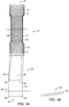
FIG. 1A is a side view of an embodiment of a prosthetic device in accordance with an embodiment of the present invention; -
FIG. 1B is a cross sectional view along line 1-1 ofFIG. 1A -
FIG. 2 is an illustration of an embodiment of a prosthetic device positioned in the lower esophageal sphincter of a patient; -
FIG. 3 is a side sectional view of an embodiment of a prosthetic device having a first valve and a second valve; -
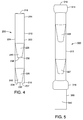
FIG. 4 is a side sectional view of an embodiment of a prosthetic device having a first valve and a second valve; -
FIG. 5 is a side sectional view of an embodiment of a prosthetic device having a first valve, a second valve and a third valve; -
FIG. 6 is a side view of an embodiment of a prosthetic device having a first valve and a second valve; -
FIG. 7 is a side view of an embodiment of a prosthetic device having a first valve and a second valve; -
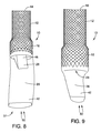
FIGS. 8-11 illustrate operation of an embodiment of a prosthetic device; and -
FIG. 12 is a cross sectional view across line 11-11 shown inFIG. 11 . - The invention is described with reference to the drawings in which like elements are referred to by like numerals. The relationship and functioning of the various elements of this invention are better understood by the following detailed description. However, the embodiments of this invention are not limited to the embodiments illustrated in the drawings. It should be understood that the drawings are not to scale, and in certain instances details have been omitted which are not necessary for an understanding of the present invention, such as conventional fabrication and assembly.
- As used in the specification, the terms proximal and distal should be understood as being in the terms of a physician delivering the prosthesis to a patient. Hence the term "distal" means the portion of the prosthesis that is farthest from the physician and the term "proximal" means the portion of the prosthesis that is nearest to the physician.
- The present invention relates to medical devices, and in particular to prosthetic devices for implantation in a body lumen such as the lower esophageal sphincter or a vessel. As used herein, the term "implantable" refers to an ability of a medical device to be positioned at a location within a body, such as within a body lumen, either temporarily, semi-permanently, or permanently. Permanent fixation of the device in a particular position is not required. Furthermore, the terms "implantation" and "implanted" refer to the positioning of a medical device at a location within a body, such as within a body lumen.
-
FIG. 1A illustrates aprosthesis 10 in accordance with an embodiment of the present invention. Theprosthesis 10 includes abody 12 havingproximal portion 14, adistal portion 16 and alumen 18 extending therethrough. In some embodiments, thebody 12 may be an expandable stent, such as a self-expanding stent. Non-limiting examples of expandable stents include the Z-Stent® and the EVOLUTION® stent (Cook Medical, Inc., Bloomington, IN). In some embodiments, thebody 12 may be a non-expandable tubular stent. Theproximal portion 14 may include anend portion 15 having an expanded outer diameter and thedistal portion 16 may include an end portion 17 having an expanded outer diameter. Thebody 12 may include a coating or asleeve 22 extending through or around thebody 12 that is liquid impermeable so that liquid and nutrients flowing from theproximal portion 14 to thedistal portion 16 or stomach contents from thedistal portion 16 to theproximal portion 14 do not pass through awall 24 of thebody 12. In some embodiments, theprosthesis 10 includes afirst valve 26 and asecond valve 28. Thefirst valve 26 and thesecond valve 28 may cooperate to better control the flow through theprosthesis 10 and the sealing of theprosthesis 10 better than a single valve device is able to do. Thefirst valve 26 may be contiguous with the coating orsleeve 22 and in some embodiments thefirst valve 26 may be separately provided. Thefirst valve 26 and thesecond valve 28 each control fluid flow through theprosthesis 10. Thefirst valve 26 and thesecond valve 28 may be provided as flexible sleeves wherein one or more of the sleeve valves may be closable on itself to cooperatively prevent stomach contents from leaking into the mouth through the prosthesis. In some embodiments, thefirst valve 26 and thesecond valve 28 may be directly connected to thebody 12. In some embodiments, thefirst valve 26 may be directly connected to thebody 12 and thesecond valve 28 may be connected to thefirst valve 26 to operably connect to thebody 12. Other configurations for operably connecting the first andsecond valves body 12 are also possible. - As shown in
FIG. 2 , theprosthesis 10 may be positioned in the loweresophageal sphincter 11. Theproximal portion 14 of thebody 12 may be positioned proximal to the loweresophageal sphincter 11. Thedistal portion 16 of thebody 12 may be positioned so that thedistal portion 16 and thefirst valve 26 extend into thestomach 13. In some embodiments, thesecond valve 28 may also extend distal to thedistal portion 16 of thebody 12 and into thestomach 13. Thefirst valve 26 remains closed in the presence of afirst pressure 44 normally present in thestomach 13 so that flow through theprosthesis 10 is substantially prevented as shown inFIG. 1B . Thesecond valve 28 may also remain closed in the presence of thefirst pressure 44. Thefirst valve 26 and thesecond valve 28 open in response to asecond pressure 48 that occurs when liquid and nutrients flow from the mouth and pass to thestomach 13. Thesecond pressure 48 is greater than thefirst pressure 44. Thefirst valve 26 and thesecond valve 28 may open in response to athird pressure 50 that is greater than the first andsecond pressures valves third pressure 50. Thethird pressure 50 pushes thevalves valves third pressure 50 built up in the stomach may be relieved through the mouth as will be explained in more detail below with reference toFIGS. 7-10 . - Referring to the embodiment shown in
FIG. 1A , thefirst valve 26 extends distally from thedistal portion 16 of thebody 12 and thesecond valve 28 extends distally from thedistal portion 16 and within alumen 32 of thefirst valve 26. In some embodiments, thesecond valve 28 extends entirely within thefirst valve 26 so that adistal end 34 of thefirst valve 26 is distal to adistal end 36 of thesecond valve 28. Thefirst valve 26 is operably connected to thebody 12 of theprosthesis 10. Thesecond valve 28 is operably connected to thebody 12 and may be connected to thebody 12 via connection to thefirst valve 26, for example when thesecond valve 28 extends entirely within thefirst valve 26. Thesecond valve 28 includes alumen 38 that is operably connected to thelumen 18 of thebody 12. In some embodiments, thelumen 32 of thefirst valve 26 may also operably connect to thelumen 18 of thebody 12. In some embodiments, only thelumen 38 of thesecond valve 28 is operably connected to thelumen 18 of thebody 12. Thelumen 38 of thesecond valve 28 operably connects to thelumen 32 of thefirst valve 26 so that liquid and nutrients and stomach contents can flow through theprosthesis 10 in response to the appropriate pressure. Adistal end portion 42 of thefirst valve 26 is normally closed in response to thefirst pressure 44 so that thedistal end portion 42 collapses on itself in the absence of liquid or nutrients flowing from the mouth to the stomach. Adistal end portion 46 of thesecond valve 28 may also be normally closed in response to thefirst pressure 44 so that thedistal end portion 46 collapses on itself. Thefirst valve 26 and thesecond valve 28 cooperatively prevent leakage of stomach contents through theprosthesis 10 in response to thefirst pressure 44, especially when the patient is in a prone position. In response to thesecond pressure 48 that is greater than thefirst pressure 44, the first and seconddistal end portions FIG. 10 ). Once the contents have passed from the mouth to the stomach, thefirst valve 26 and in some embodiments, thesecond valve 28, return to the closed position. In response to thethird pressure 50, the first andsecond valves third pressure 50 and flow is in a secondretrograde direction 51 as shown inFIGS. 7-10 and described in more detail below. -
FIG. 3 illustrates an embodiment of aprosthesis 100. Theprosthesis 100 includes abody 112 havingproximal portion 114, adistal portion 116 and alumen 118 extending therethrough. Similar to theprosthesis 10 described above, theprosthesis 100 may include an expandable or a non-expandable stent. Thebody 112 may include a coating or avalve 122 extending through or around thebody 112 that is liquid impermeable so that flow of liquid and nutrients passing from theproximal portion 114 to thedistal portion 116 or stomach contents from thedistal portion 116 to theproximal portion 114 do not pass through awall 124 of thebody 112. Theprosthesis 100 includes afirst valve 126 and asecond valve 128. In some embodiments, thefirst valve 126 and thesecond valve 128 may be provided as flexible sleeves. - As shown in
FIG. 3 , thefirst valve 126 extends distally from thedistal portion 116 of thebody 112 so that adistal end 134 of thefirst valve 126 extends distal to thedistal portion 116 of thebody 112. Thesecond valve 128 extends distally from thebody 112 and is positioned proximal to thefirst valve 126. As shown inFIG. 3 , thesecond valve 128 is spaced apart from thefirst valve 126. Thesecond valve 128 may extend distally such that adistal end 136 of thesecond valve 128 is entirely within thelumen 118 of thebody 112. As shown inFIG. 3 , thesecond valve 128 may extend distally from theproximal portion 114 of thebody 112. In other embodiments, thesecond valve 128 may extend from any portion of thebody 112. In some embodiments, thedistal end 136 of thesecond valve 128 is proximal to aproximal end 152 of thefirst valve 126. In some embodiments, thefirst valve 126 may extend from theproximal portion 114 of thebody 112 and distal to thedistal portion 116 of thebody 112. Thesecond valve 128 may extend within alumen 132 of thefirst valve 126 extending from theproximal portion 114 and be positioned entirely within thebody 112. - The
second valve 128 includes alumen 138 that is operably connected to thelumen 118 of thebody 112. Thelumen 132 of thefirst valve 126 is also operably connected to thelumen 118 of thebody 112 so that flow of liquid and nutrients can pass from the mouth to the stomach. Adistal end portion 142 of thefirst valve 126 is normally closed in response to thefirst pressure 44 so that thedistal end portion 142 collapses on itself in the absence of flow from the mouth to the stomach. Adistal end portion 146 of thesecond valve 128 may also be normally closed in response to thefirst pressure 44 so that thedistal end portion 146 collapses on itself. Thefirst valve 126 and thesecond valve 128 cooperatively prevent leakage of stomach contents through theprosthesis 100 in response to thefirst pressure 44, especially when the patient is in a prone position. In response to thesecond pressure 48 that is greater than thefirst pressure 44, the first and seconddistal end portions FIG. 10 ). Once the contents have passed from the mouth to the stomach, thefirst valve 126 and in some embodiments, thesecond valve 128, return to theclosed position 55. In response to thethird pressure 50, thesecond valve 128 inverts and thefirst valve 126 inverts to relieve thethird pressure 50 as described in more detail below. Thefirst valve 126 may be sized and shaped so that when thefirst valve 126 and thesecond valve 128 invert and open in response to thethird pressure 50, thefirst valve 126 does not contact thesecond valve 128. -
FIG. 4 illustrates an embodiment of aprosthesis 200. Theprosthesis 200 includes abody 212 havingproximal portion 214, adistal portion 216 and alumen 218 extending therethrough. Similar to theprosthesis 10 described above, theprosthesis 200 may include an expandable or a non-expandable stent. Thebody 212 may include a coating or asleeve 222 extending through or around thebody 212 that is liquid impermeable so that liquid and nutrients flowing from theproximal portion 214 to thedistal portion 216 or stomach contents from thedistal portion 216 to theproximal portion 214 do not pass through awall 224 of thebody 212. Theprosthesis 200 includes afirst valve 226 and asecond valve 228. In some embodiments,first valve 226 and thesecond valve 228 may be provided as flexible sleeves. - As shown in
FIG. 4 , a distal end of thefirst valve 226 and a distal end of thesecond valve 228 extend distally toward thedistal portion 216 of thebody 212. Thefirst valve 226 and thesecond valve 228 may be positioned within thebody 212 of theprosthesis 200 so that the distal ends 234, 236 are both proximal to adistal end 237 of thebody 212. As shown inFIG. 4 , thesecond valve 228 extends distally from thebody 112 and is positioned proximal to thefirst valve 226. In some embodiments, thesecond valve 228 is spaced apart from thefirst valve 226. In some embodiments, thesecond valve 228 may extend at least partially within alumen 232 of thefirst valve 226. - Similar to the embodiments described above, the
second valve 228 includes alumen 238 that is operably connected to thelumen 218 of thebody 112. Thelumen 232 of thefirst valve 226 is also operably connected to thelumen 218 of thebody 212 so that fluids and nutrients can flow from the mouth to the stomach. Adistal end portion 242 of thefirst valve 226 is normally closed in response to thefirst pressure 44 so that thedistal end portion 242 collapses. Adistal end portion 246 of thesecond valve 228 may also be normally closed in response to thefirst pressure 44 so that thedistal end portion 246 collapses on itself. Thefirst valve 226 and thesecond valve 228 cooperatively prevent leakage of stomach contents through theprosthesis 200 in response to thefirst pressure 44, especially when the patient is in a prone position. In response to thesecond pressure 48 that is greater than thefirst pressure 44, the first and seconddistal end portions first valve 226 and in some embodiments, thesecond valve 228, return to the closed position. In response to thethird pressure 50, thesecond valve 228 inverts and thefirst valve 226 inverts to relieve thethird pressure 50 as described in more detail below. Thefirst valve 226 may be sized and shaped so that when thefirst valve 226 and thesecond valve 228 invert and open in response to thethird pressure 50, thefirst valve 226 does not contact thesecond valve 228. -
FIG. 5 illustrates an embodiment of aprosthesis 300. Theprosthesis 300 is similar to the embodiments described above and additionally includes athird valve 327 positioned between afirst valve 326 and asecond valve 328. Theprosthesis 300 includes abody 312 havingproximal portion 314, adistal portion 316 and alumen 318 extending therethrough. Thevalves third pressures prosthesis 300 is normally closed in response to thefirst pressure 44 with at least adistal end 342 of thefirst valve 326 collapsed on itself in the presence of thefirst pressure 44. Thefirst valve 326, thesecond valve 328 and thethird valve 327 cooperatively prevent leakage of stomach contents through theprosthesis 300 in response to thefirst pressure 44, especially when the patient is in a prone position. The prosthesis is normally open in response to thesecond pressure 48 so that liquids and nutrients can flow from the mouth to the stomach through theprosthesis 300. Theprosthesis 300 is normally open in response to thethird pressure 50 wherein thevalves -
FIG. 6 illustrates aprosthesis 400 in accordance with an embodiment of the present invention. Theprosthesis 400 includes abody 412 havingproximal portion 414, adistal portion 416 and a lumen 418 extending therethrough. Similar to the embodiments described above, thebody 412 may be an expandable or a non-expandable stent. Thebody 412 may include a coating or avalve 422 extending through or around thebody 412 that is liquid impermeable. In some embodiments, theprosthesis 400 includes afirst valve 426 and asecond valve 428. Thefirst valve 426 may be contiguous with the coating orsleeve 422 and in some embodiments thefirst valve 426 may be separately provided. In some embodiments, thefirst valve 426 and thesecond valve 428 may be provided as flexible sleeves - As shown in
FIG. 6 , thefirst valve 426 may include one ormore openings 456 through awall 458 of thefirst valve 426. Theopenings 456 may facilitate drainage for any leaks through theprosthesis 400 so that the contents may be returned to the stomach. Thesecond valve 428 may include one ormore openings 462 through awall 464 of thesecond valve 428. Theopenings 462 facilitate drainage for any leaks through theprosthesis 400 so that the contents may be returned to the stomach. Theopenings 462 may be offset from theopenings 456 to prevent leakage from the stomach to the mouth, for example while the patient is in a prone position. Theprosthesis 400 is similar to the embodiments shown above and responds to the first, second andthird pressures prosthesis 400 remains closed in response to thefirst pressure 44 and is open in response to the second andthird pressures -
FIG. 7 illustrates an embodiment of aprosthesis 500. Theprosthesis 500 includes abody 512 havingproximal portion 514, adistal portion 516 and alumen 518 extending therethrough. Similar to theprosthesis 10 described above, theprosthesis 500 may include an expandable or a non-expandable stent. Thebody 512 may include a coating or asleeve 522 extending through or around thebody 512 that is liquid impermeable so that liquid and nutrients flowing from theproximal portion 514 to thedistal portion 516 or stomach contents from thedistal portion 516 to theproximal portion 514 do not pass through awall 524 of thebody 512. Theprosthesis 500 includes afirst valve 526 and asecond valve 528. - The
first valve 526 and thesecond valve 528 may be configured to respond to different pressures when placed within a body lumen. In some embodiments, the prosthesis may include a non-invertingfirst valve 526 and an invertingsecond valve 528. Similar to the embodiments described above, thesecond valve 528 includes alumen 538 that is operably connected to thelumen 518 of thebody 512. Alumen 532 of thefirst valve 526 is also operably connected to thelumen 518 of thebody 512 so that fluids and nutrients can flow from the mouth to the stomach. Adistal end portion 542 of thefirst valve 526 may be normally closed. Adistal end portion 546 of thesecond valve 528 may also be normally closed. Thefirst valve 526 and thesecond valve 528 cooperatively prevent leakage of stomach contents through theprosthesis 500 in response to thefirst pressure 44, especially when the patient is in a prone position. In response to thesecond pressure 48 that is greater than thefirst pressure 44, the first and seconddistal end portions first valve 526 and in some embodiments, thesecond valve 528, return to the closed position. In response to thethird pressure 50, thesecond valve 528 inverts to relieve thethird pressure 50 and thefirst valve 526 does not invert. Thefirst valve 526 may be configured to allow the passage of food and fluid to the stomach. Thefirst valve 526 may be configured to form a shape that creates a protective barrier against reflux/aspiration at low pressures. Aportion 533 of thefirst valve 526 may be attached to thebody 512 and/or include asupport structure 535 attached to thebody 512 to prevent thefirst valve 526 from inverting. In some embodiments, thefirst valve 526 may have a thickness that would prevent thefirst valve 526 from inverting. For example, the thickness of thefirst valve 526 may be greater than about 0.6 mm. As shown inFIG. 7 , the non-invertingfirst valve 526 may be larger than the invertingsecond valve 528. - As shown in
FIG. 7 , theprosthesis 500 may include thesecond valve 528 positioned outside thefirst valve 526 and connected to thebody 512. Thesecond valve 528 may be configured to allow the patient to belch or vomit in response to the increasedpressure 50 within the stomach. Thesecond valve 528 may have a smaller diameter than thefirst valve 526. In some embodiments the ratio of the diameter of thesecond valve 528 to the diameter of thefirst valve 526 is a ratio of about 1:4. By way of non-limiting example, the diameter of the first valve may be about 15-35 mm. The diameter of thesecond valve 528 may be about 2.0-15 mm. Thesecond valve 528 may be shorter, equal to or longer than thefirst valve 526. In some embodiments, thefirst valve 528 may have a length of about 0.5 cm to about 5 cm. Thesecond valve 528 may have a length of about 0.5 cm to about 4 cm. - In some embodiments, the
prosthesis 500 may include the firstnon-inverting valve 526, thesecond inverting valve 528 and a third inverting valve (not shown). The third inverting valve may be sized and shaped similarly to thesecond inverting valve 528. - The materials used to manufacture the components of the prosthetic devices described herein may be any materials known to one skilled in the art that are suitable for use in patients. By way of non-limiting example, the body may be formed from metals or polymers. Suitable exemplary metals include stainless steel and nitinol and the body may be woven or provided in a zig-zag configuration. Valves of the prosthetic devices of the embodiments may be made from any suitable biocompatible material that is liquid impermeable and that does not degrade in the presence of fluids or gastric material that comes in contact therewith. By way of non-limiting example, the valve may be made from a medical grade polyurethane material, silicone, nylon, polyamides such as other urethanes, polyethylene , polyethylene terephthalate (PET), polystyrene-ethylene (PSE), polytetrafluoroethylene (PTFE), ultrahigh molecular weight, low density and high density polyethylene, elastomeric polyethylene, polyethyleneoxide (PEO), block copolymers containing polystyrene and poly(1,4-butadiene), ABA triblock copolymer made from poly(2-methyl-2-oxazoline), polytetrahydrofuran, shape memory polymers, amorphous or organic-inorganic hybrid polymers containing polymorbornere units or other biocompatible materials that are flexible and acid resistant. In some embodiments, portions of the valve may be made from biodegradable materials such as PLA, PLGA, PBA or nitinol. An exemplary material for the valve is a medical grade polyurethane material grade EG-80A material commercially known as TECOFLEX® polyurethane material (Thermedics, Incorporated, Woburn, MA).
- The first valve and the second valve of the embodiments described above may be made from the same or different materials. In some embodiments, the first valve or a portion thereof may be made of a heavier gauge material relative to the second valve. The first valve may be configured to be stiffer than the second valve so that the second valve inverts more readily in response to the third pressure than the first valve. The first valve may be made stiffer by providing a material having a greater thickness relative to the first valve. In some embodiments, the first valve may have a different shape than the second valve so that the second valve inverts more readily than the first valve in response to the third pressure. In some embodiments, the first valve and the second valve may be made from the same material and have the same stiffness so that both the first and the second valve invert in response to the same third pressure. The third valve, when present, may be the same as the first valve, the second valve or both or may be different than both the first valve and the second valve.
- In some embodiments, the length of the first valve extending from the distal end of the body of the prosthesis may be from about 0 cm to about 20 cm, from from about 5 cm to about 15 cm and from about 8 cm to about 12 cm. The length may vary and will depend on anatomy of the patient. In some embodiments, the thickness of the first and second valves may be from about 0.1 mm to about 3.0 mm. In some embodiments, the distal end portions of the first and second valves may be about 0.05 mm to about 0.15 mm while the remainder of the each valve has a greater thickness. In some embodiments, the thickness of the distal end portion of the first valve may be greater than the thickness of the distal end portion of the second valve.
- Operation of the prosthesis will be explained with reference to the
prosthesis 10 as an example. Operation of theprosthesis 10 is shown inFIGS. 1A and8-12 . Theprosthesis 10 may be delivered to the LES using a delivery catheter (not shown) and positioned in the LES so that theproximal portion 14 of thebody 12 is positioned above thesphincter 11 and thedistal portion 16 of thebody 12 is positioned in thestomach 13. (SeeFIG. 2 .) Thefirst valve 26 and thesecond valve 28 may be delivered to the LES with thefirst valve 26 and thesecond valve 28 positioned within thelumen 18 of thebody 12 or extending distally with the first valve extending distally from thedistal portion 16 of thebody 12. When the first andsecond valves lumen 18 of thebody 12 to the LES, thevalves body 12 in the sphincter by having the patient drink a liquid so that thesecond pressure 48 is applied and thevalves -
FIG. 1A illustrates theprosthesis 10 in aclosed configuration 55 with the first andsecond valves prosthesis 10 is closed so that gastric contents under thefirst pressure 44 are prevented from flowing from thestomach 13 to the mouth of the patient. Thefirst valve 26 is collapsed upon itself at thedistal end portion 42. Theprosthesis 10 also has anopen configuration 57 shown inFIGS. 11 and 12 where thelumen 32 of thefirst valve 26 and thelumen 38 of thesecond valve 28 are open in response to thesecond pressure 48 so that liquids and nutrients can flow through theprosthesis 10 from the mouth to thestomach 13. - As discussed above, the first and second valves of the prosthesis in certain embodiments may invert at different rates in response to the
third pressure 50 depending on the materials, shapes and thicknesses of the first and second valves relative to each other.FIGS. 8-10 illustrate an embodiment of theprosthesis 10 inverting in response to thethird pressure 50. As shown inFIG. 8 , thesecond valve 28 of theprosthesis 10 may invert in response to thethird pressure 50 more readily than thefirst valve 26. Thesecond valve 28 is shown with thedistal end portion 46 of thesecond valve 28 inverting into thelumen 18 of thebody 12. Thefirst valve 26 is shown with thedistal end portion 42 of thefirst valve 26 extending distally from thedistal portion 16 of thebody 12 while thesecond valve 28 inverts.FIG. 9 illustrates thesecond valve 28 completely inverted and extending proximally through thelumen 18 of thebody 12 so that thelumen 38 of thesecond valve 28 is open. Thefirst valve 26 is shown beginning to invert in response to thethird pressure 50 so that thedistal end portion 42 moves proximally toward thelumen 18 of thebody 12. -
FIG. 10 illustrates both thefirst valve 26 and thesecond valve 28 inverted into thelumen 18 of thebody 12 in aninverted configuration 59. In theinverted configuration 59, thedistal end portions second valves lumen 18 of thebody 12 and thelumens second valves third pressure 50 so that the patient can belch or vomit. Once thethird pressure 50 is relieved, the first andsecond valves distal end portions second valves body 12 of theprosthesis 10. As discussed above, theprosthesis 10 may be returned to theopen configuration 57 by the patient swallowing a liquid to provide thesecond pressure 48. Theprosthesis 10 may then be closed and remain in the closed configuration 55 (shown inFIG. 1A ) in the presence of thefirst pressure 44. - The above Figures and disclosure are intended to be illustrative and not exhaustive. This description will suggest many variations and alternatives to one of ordinary skill in the art. All such variations and alternatives are intended to be encompassed within the scope of the attached claims. Those familiar with the art may recognize other equivalents to the specific embodiments described herein which equivalents are also intended to be encompassed by the attached claims.
Claims (15)
- A prosthesis for controlling flow through a bodily lumen, the prosthesis comprising:a body having a proximal portion, a distal portion and a lumen extending therethrough;a first valve operably connected to the body, the first valve having a proximal portion, a distal portion, a distal end extending distally relative to the proximal portion of the body and a lumen extending through the first valve, the first valve being closed in the absence of a second and a third pressure that are greater than a first pressure; anda second valve operably connected to the body, the second valve having a proximal portion, a distal portion, a distal end extending distally relative to the proximal portion of the body and a lumen extending through the second valve, the distal end of the first valve extending distal to the distal end of the second valve, the second valve and the first valve controlling flow through the prosthesis.
- The prosthesis according to claim 1, wherein at least a portion of the second valve extends distally within the lumen of the first valve.
- The prosthesis according to claim 1, wherein the second valve is spaced apart from first valve so that the distal end of the second valve is proximal to a proximal end of the first valve.
- The prosthesis according to any one of claims 1-3, wherein proximal portion of the first valve comprises a sleeve disposed about the body.
- The prosthesis according to any one of claims 1-4, wherein the second valve is closed in in the absence of the second and the third pressure.
- The prosthesis according to any one of claims 1-5, wherein the distal portion of the first valve and the distal portion of the second valve are positioned entirely within the body.
- The prosthesis according to any one of claims 1-6, wherein the first valve, the second valve or both comprise at least one hole extending therethrough.
- The prosthesis according to any one of claims 1-7, wherein the distal portion of the first valve and the distal portion of the second valve have different thicknesses.
- The prosthesis according to any one of claims 1-8, wherein at least of portion of the first valve and at least a portion of the second valve are formed from different materials.
- The prosthesis according to any one of claims 1-9, further comprising a third valve positioned between the first valve and the second valve.
- The prosthesis according to any one of claims 1-10, wherein the first valve is a non-inverting valve and the second valve is an inverting valve.
- The prosthesis according to any one of claims 1-11, wherein the first valve comprises a sleeve of flexible material.
- The prosthesis according to claim 1, wherein the distal end of the first valve extends distal to a distal end of the body or the distal end of the first valve and the distal end of the second valve extend distal to a distal end of the body.
- The prosthesis according to any one of claims 1-12, wherein the second valve is connected to the first valve to operably connect to the body.
- The prosthesis according to claim 1, wherein the distal end of the first valve and the distal end of the second valve are proximally extendable in response to a third pressure that is greater than the first pressure and a second pressure.
Applications Claiming Priority (1)
| Application Number | Priority Date | Filing Date | Title |
|---|---|---|---|
| US201361750183P | 2013-01-08 | 2013-01-08 |
Publications (2)
| Publication Number | Publication Date |
|---|---|
| EP2752170A1 true EP2752170A1 (en) | 2014-07-09 |
| EP2752170B1 EP2752170B1 (en) | 2017-02-22 |
Family
ID=49911396
Family Applications (1)
| Application Number | Title | Priority Date | Filing Date |
|---|---|---|---|
| EP14150223.7A Active EP2752170B1 (en) | 2013-01-08 | 2014-01-06 | Multi valve anti-reflux prosthesis |
Country Status (2)
| Country | Link |
|---|---|
| US (1) | US9526605B2 (en) |
| EP (1) | EP2752170B1 (en) |
Cited By (2)
| Publication number | Priority date | Publication date | Assignee | Title |
|---|---|---|---|---|
| WO2017044929A1 (en) * | 2015-09-11 | 2017-03-16 | Parker-Haniifin Corporation | Endoscopically deployable anti-reflux device |
| WO2017199098A1 (en) * | 2016-05-20 | 2017-11-23 | Siersema Peter Derk | Device and method for treatment of barrett's esophagus |
Families Citing this family (18)
| Publication number | Priority date | Publication date | Assignee | Title |
|---|---|---|---|---|
| US20040143342A1 (en) * | 2003-01-16 | 2004-07-22 | Stack Richard S. | Satiation pouches and methods of use |
| US8579964B2 (en) | 2010-05-05 | 2013-11-12 | Neovasc Inc. | Transcatheter mitral valve prosthesis |
| US9554897B2 (en) | 2011-04-28 | 2017-01-31 | Neovasc Tiara Inc. | Methods and apparatus for engaging a valve prosthesis with tissue |
| US9308087B2 (en) | 2011-04-28 | 2016-04-12 | Neovasc Tiara Inc. | Sequentially deployed transcatheter mitral valve prosthesis |
| US9345573B2 (en) | 2012-05-30 | 2016-05-24 | Neovasc Tiara Inc. | Methods and apparatus for loading a prosthesis onto a delivery system |
| US9572665B2 (en) | 2013-04-04 | 2017-02-21 | Neovasc Tiara Inc. | Methods and apparatus for delivering a prosthetic valve to a beating heart |
| JP7002451B2 (en) | 2015-12-15 | 2022-01-20 | ニオバスク ティアラ インコーポレイテッド | Transseptal delivery system |
| CN108882981B (en) | 2016-01-29 | 2021-08-10 | 内奥瓦斯克迪亚拉公司 | Prosthetic valve for preventing outflow obstruction |
| AU2017361296B2 (en) | 2016-11-21 | 2022-09-29 | Neovasc Inc. | Methods and systems for rapid retraction of a transcatheter heart valve delivery system |
| EP3672530A4 (en) | 2017-08-25 | 2021-04-14 | Neovasc Tiara Inc. | SEQUENTIAL DEPLOYMENT TRANSCATHETER MITRAL VALVE PROSTHESIS |
| AU2019374743B2 (en) | 2018-11-08 | 2022-03-03 | Neovasc Inc. | Ventricular deployment of a transcatheter mitral valve prosthesis |
| CN113747863B (en) | 2019-03-08 | 2024-11-08 | 内奥瓦斯克迪亚拉公司 | Retrievable Prosthesis Delivery System |
| AU2020256195B2 (en) | 2019-04-01 | 2022-10-13 | Neovasc Inc. | Controllably deployable prosthetic valve |
| US11491006B2 (en) | 2019-04-10 | 2022-11-08 | Neovasc Tiara Inc. | Prosthetic valve with natural blood flow |
| CA3282225A1 (en) | 2019-05-20 | 2026-03-02 | Neovasc Tiara Inc. | Introducer with hemostasis mechanism |
| JP7520897B2 (en) | 2019-06-20 | 2024-07-23 | ニオバスク ティアラ インコーポレイテッド | Thin prosthetic mitral valve |
| US11559385B2 (en) | 2020-04-24 | 2023-01-24 | Jt Godfrey, Llc | Device for use with body tissue sphincters |
| US11628052B2 (en) | 2020-05-13 | 2023-04-18 | Jt Godfrey, Llc | Device for use with body tissue sphincters |
Citations (7)
| Publication number | Priority date | Publication date | Assignee | Title |
|---|---|---|---|---|
| US4846836A (en) * | 1988-10-03 | 1989-07-11 | Reich Jonathan D | Artificial lower gastrointestinal valve |
| WO2001066190A2 (en) * | 2000-03-04 | 2001-09-13 | Emphasys Medical, Inc. | Methods and devices for use in performing pulmonary procedures |
| WO2005011534A1 (en) * | 2003-07-31 | 2005-02-10 | Cook Incorporated | Prosthetic valve devices and methods of making such devices |
| EP1952785A1 (en) * | 2005-11-16 | 2008-08-06 | Yingsheng Cheng | A cardia stent |
| US20120089236A1 (en) * | 2010-10-08 | 2012-04-12 | E2 Llc | Anti-Reflux Devices and Methods for Treating Gastro-Esophageal Reflux Disease (GERD) |
| WO2013144770A2 (en) * | 2012-03-17 | 2013-10-03 | Pinzi Novello | A structure of artificial endo-urethral sphincter |
| WO2014022500A1 (en) * | 2012-07-31 | 2014-02-06 | The Charles Stark Draper Laboratory, Inc. | Implantable device for directional control of flow within the anatomic tracts of the body |
Family Cites Families (28)
| Publication number | Priority date | Publication date | Assignee | Title |
|---|---|---|---|---|
| GB1354691A (en) | 1970-02-12 | 1974-05-30 | Black M M | Fluid-operated valves |
| US4434810A (en) | 1980-07-14 | 1984-03-06 | Vernay Laboratories, Inc. | Bi-directional pressure relief valve |
| US5314473A (en) | 1989-07-20 | 1994-05-24 | Godin Norman J | Prosthesis for preventing gastric reflux into the esophagus |
| US5392775A (en) | 1994-03-22 | 1995-02-28 | Adkins, Jr.; Claude N. | Duckbill valve for a tracheostomy tube that permits speech |
| CH688174A5 (en) | 1995-03-28 | 1997-06-13 | Norman Godin | Prosthesis to oppose the gastric reflux into the esophagus. |
| US6254642B1 (en) | 1997-12-09 | 2001-07-03 | Thomas V. Taylor | Perorally insertable gastroesophageal anti-reflux valve prosthesis and tool for implantation thereof |
| US6264700B1 (en) | 1998-08-27 | 2001-07-24 | Endonetics, Inc. | Prosthetic gastroesophageal valve |
| AU747060B2 (en) | 1998-08-31 | 2002-05-09 | Cook Medical Technologies Llc | Anti-reflux esophageal prosthesis |
| US20080086214A1 (en) | 1998-08-31 | 2008-04-10 | Wilson-Cook Medical Inc. | Medical device having a sleeve valve with bioactive agent |
| US7118600B2 (en) | 1998-08-31 | 2006-10-10 | Wilson-Cook Medical, Inc. | Prosthesis having a sleeve valve |
| US6746489B2 (en) | 1998-08-31 | 2004-06-08 | Wilson-Cook Medical Incorporated | Prosthesis having a sleeve valve |
| US20070027535A1 (en) * | 2005-07-28 | 2007-02-01 | Cook Incorporated | Implantable thromboresistant valve |
| US6845776B2 (en) | 2001-08-27 | 2005-01-25 | Richard S. Stack | Satiation devices and methods |
| US6790237B2 (en) | 2001-10-09 | 2004-09-14 | Scimed Life Systems, Inc. | Medical stent with a valve and related methods of manufacturing |
| KR100442330B1 (en) | 2002-09-03 | 2004-07-30 | 주식회사 엠아이텍 | Stent and manufacturing method the same |
| US20040102855A1 (en) | 2002-11-21 | 2004-05-27 | Scimed Life Systems, Inc. | Anti-reflux stent |
| US8128681B2 (en) | 2003-12-19 | 2012-03-06 | Boston Scientific Scimed, Inc. | Venous valve apparatus, system, and method |
| AU2005260008B2 (en) | 2004-06-29 | 2009-07-16 | The Cleveland Clinic Foundation | Prosthetic cardiac valve and method for making same |
| KR100691503B1 (en) | 2005-03-21 | 2007-03-09 | (주) 태웅메디칼 | Esophageal Stents |
| US20070213813A1 (en) | 2005-12-22 | 2007-09-13 | Symetis Sa | Stent-valves for valve replacement and associated methods and systems for surgery |
| AU2006328896B2 (en) | 2005-12-22 | 2013-08-29 | Symetis Sa | Stent-valves for valve replacement and associated methods and systems for surgery |
| US9308077B2 (en) | 2005-12-23 | 2016-04-12 | Vysera Biomedical Limited | Medical device suitable for treating reflux from a stomach to an oesophagus |
| US8221505B2 (en) | 2007-02-22 | 2012-07-17 | Cook Medical Technologies Llc | Prosthesis having a sleeve valve |
| WO2009153770A1 (en) | 2008-06-20 | 2009-12-23 | Vysera Biomedical Limited | Esophageal valve |
| US20100114327A1 (en) | 2008-06-20 | 2010-05-06 | Vysera Biomedical Limited | Valve |
| US20110160836A1 (en) | 2008-06-20 | 2011-06-30 | Vysera Biomedical Limited | Valve device |
| AU2010331821B2 (en) | 2009-12-18 | 2016-02-25 | Coloplast A/S | A gastrointestinal implant device |
| US20120158026A1 (en) | 2009-12-18 | 2012-06-21 | Vysera Biomedical Limited | Gastrointestinal implant device |
-
2014
- 2014-01-06 EP EP14150223.7A patent/EP2752170B1/en active Active
- 2014-01-07 US US14/149,104 patent/US9526605B2/en active Active
Patent Citations (7)
| Publication number | Priority date | Publication date | Assignee | Title |
|---|---|---|---|---|
| US4846836A (en) * | 1988-10-03 | 1989-07-11 | Reich Jonathan D | Artificial lower gastrointestinal valve |
| WO2001066190A2 (en) * | 2000-03-04 | 2001-09-13 | Emphasys Medical, Inc. | Methods and devices for use in performing pulmonary procedures |
| WO2005011534A1 (en) * | 2003-07-31 | 2005-02-10 | Cook Incorporated | Prosthetic valve devices and methods of making such devices |
| EP1952785A1 (en) * | 2005-11-16 | 2008-08-06 | Yingsheng Cheng | A cardia stent |
| US20120089236A1 (en) * | 2010-10-08 | 2012-04-12 | E2 Llc | Anti-Reflux Devices and Methods for Treating Gastro-Esophageal Reflux Disease (GERD) |
| WO2013144770A2 (en) * | 2012-03-17 | 2013-10-03 | Pinzi Novello | A structure of artificial endo-urethral sphincter |
| WO2014022500A1 (en) * | 2012-07-31 | 2014-02-06 | The Charles Stark Draper Laboratory, Inc. | Implantable device for directional control of flow within the anatomic tracts of the body |
Cited By (2)
| Publication number | Priority date | Publication date | Assignee | Title |
|---|---|---|---|---|
| WO2017044929A1 (en) * | 2015-09-11 | 2017-03-16 | Parker-Haniifin Corporation | Endoscopically deployable anti-reflux device |
| WO2017199098A1 (en) * | 2016-05-20 | 2017-11-23 | Siersema Peter Derk | Device and method for treatment of barrett's esophagus |
Also Published As
| Publication number | Publication date |
|---|---|
| US9526605B2 (en) | 2016-12-27 |
| EP2752170B1 (en) | 2017-02-22 |
| US20140195006A1 (en) | 2014-07-10 |
Similar Documents
| Publication | Publication Date | Title |
|---|---|---|
| EP2752170B1 (en) | Multi valve anti-reflux prosthesis | |
| US9358095B2 (en) | Anti-reflux prosthesis | |
| US9427303B2 (en) | Anti-aspiration valve | |
| EP1411867B1 (en) | Prosthesis having a sleeve valve | |
| EP2112912B1 (en) | Prosthesis having a sleeve valve | |
| US6746489B2 (en) | Prosthesis having a sleeve valve | |
| US10231819B2 (en) | Anti-aspiration prosthesis | |
| US8801647B2 (en) | Use of a gastrointestinal sleeve to treat bariatric surgery fistulas and leaks | |
| AU2002324563A1 (en) | Prosthesis having a sleeve valve | |
| US20140031951A1 (en) | Two-Way Valve | |
| JP2008528206A (en) | Prosthesis with sleeve valve | |
| JP2025159227A (en) | Devices, systems, and methods for duodenal emptying and gastric volume reduction |
Legal Events
| Date | Code | Title | Description |
|---|---|---|---|
| 17P | Request for examination filed |
Effective date: 20140106 |
|
| AK | Designated contracting states |
Kind code of ref document: A1 Designated state(s): AL AT BE BG CH CY CZ DE DK EE ES FI FR GB GR HR HU IE IS IT LI LT LU LV MC MK MT NL NO PL PT RO RS SE SI SK SM TR |
|
| AX | Request for extension of the european patent |
Extension state: BA ME |
|
| PUAI | Public reference made under article 153(3) epc to a published international application that has entered the european phase |
Free format text: ORIGINAL CODE: 0009012 |
|
| R17P | Request for examination filed (corrected) |
Effective date: 20141230 |
|
| RBV | Designated contracting states (corrected) |
Designated state(s): AL AT BE BG CH CY CZ DE DK EE ES FI FR GB GR HR HU IE IS IT LI LT LU LV MC MK MT NL NO PL PT RO RS SE SI SK SM TR |
|
| 17Q | First examination report despatched |
Effective date: 20150617 |
|
| GRAP | Despatch of communication of intention to grant a patent |
Free format text: ORIGINAL CODE: EPIDOSNIGR1 |
|
| INTG | Intention to grant announced |
Effective date: 20160803 |
|
| GRAS | Grant fee paid |
Free format text: ORIGINAL CODE: EPIDOSNIGR3 |
|
| GRAJ | Information related to disapproval of communication of intention to grant by the applicant or resumption of examination proceedings by the epo deleted |
Free format text: ORIGINAL CODE: EPIDOSDIGR1 |
|
| GRAL | Information related to payment of fee for publishing/printing deleted |
Free format text: ORIGINAL CODE: EPIDOSDIGR3 |
|
| GRAR | Information related to intention to grant a patent recorded |
Free format text: ORIGINAL CODE: EPIDOSNIGR71 |
|
| INTC | Intention to grant announced (deleted) | ||
| INTG | Intention to grant announced |
Effective date: 20161202 |
|
| GRAA | (expected) grant |
Free format text: ORIGINAL CODE: 0009210 |
|
| AK | Designated contracting states |
Kind code of ref document: B1 Designated state(s): AL AT BE BG CH CY CZ DE DK EE ES FI FR GB GR HR HU IE IS IT LI LT LU LV MC MK MT NL NO PL PT RO RS SE SI SK SM TR |
|
| REG | Reference to a national code |
Ref country code: GB Ref legal event code: FG4D |
|
| REG | Reference to a national code |
Ref country code: CH Ref legal event code: EP |
|
| REG | Reference to a national code |
Ref country code: AT Ref legal event code: REF Ref document number: 868679 Country of ref document: AT Kind code of ref document: T Effective date: 20170315 |
|
| REG | Reference to a national code |
Ref country code: IE Ref legal event code: FG4D |
|
| REG | Reference to a national code |
Ref country code: DE Ref legal event code: R096 Ref document number: 602014006839 Country of ref document: DE |
|
| REG | Reference to a national code |
Ref country code: LT Ref legal event code: MG4D |
|
| REG | Reference to a national code |
Ref country code: NL Ref legal event code: MP Effective date: 20170222 |
|
| REG | Reference to a national code |
Ref country code: AT Ref legal event code: MK05 Ref document number: 868679 Country of ref document: AT Kind code of ref document: T Effective date: 20170222 |
|
| PG25 | Lapsed in a contracting state [announced via postgrant information from national office to epo] |
Ref country code: GR Free format text: LAPSE BECAUSE OF FAILURE TO SUBMIT A TRANSLATION OF THE DESCRIPTION OR TO PAY THE FEE WITHIN THE PRESCRIBED TIME-LIMIT Effective date: 20170523 Ref country code: NO Free format text: LAPSE BECAUSE OF FAILURE TO SUBMIT A TRANSLATION OF THE DESCRIPTION OR TO PAY THE FEE WITHIN THE PRESCRIBED TIME-LIMIT Effective date: 20170522 Ref country code: HR Free format text: LAPSE BECAUSE OF FAILURE TO SUBMIT A TRANSLATION OF THE DESCRIPTION OR TO PAY THE FEE WITHIN THE PRESCRIBED TIME-LIMIT Effective date: 20170222 Ref country code: LT Free format text: LAPSE BECAUSE OF FAILURE TO SUBMIT A TRANSLATION OF THE DESCRIPTION OR TO PAY THE FEE WITHIN THE PRESCRIBED TIME-LIMIT Effective date: 20170222 Ref country code: FI Free format text: LAPSE BECAUSE OF FAILURE TO SUBMIT A TRANSLATION OF THE DESCRIPTION OR TO PAY THE FEE WITHIN THE PRESCRIBED TIME-LIMIT Effective date: 20170222 |
|
| PG25 | Lapsed in a contracting state [announced via postgrant information from national office to epo] |
Ref country code: LV Free format text: LAPSE BECAUSE OF FAILURE TO SUBMIT A TRANSLATION OF THE DESCRIPTION OR TO PAY THE FEE WITHIN THE PRESCRIBED TIME-LIMIT Effective date: 20170222 Ref country code: AT Free format text: LAPSE BECAUSE OF FAILURE TO SUBMIT A TRANSLATION OF THE DESCRIPTION OR TO PAY THE FEE WITHIN THE PRESCRIBED TIME-LIMIT Effective date: 20170222 Ref country code: ES Free format text: LAPSE BECAUSE OF FAILURE TO SUBMIT A TRANSLATION OF THE DESCRIPTION OR TO PAY THE FEE WITHIN THE PRESCRIBED TIME-LIMIT Effective date: 20170222 Ref country code: BG Free format text: LAPSE BECAUSE OF FAILURE TO SUBMIT A TRANSLATION OF THE DESCRIPTION OR TO PAY THE FEE WITHIN THE PRESCRIBED TIME-LIMIT Effective date: 20170522 Ref country code: RS Free format text: LAPSE BECAUSE OF FAILURE TO SUBMIT A TRANSLATION OF THE DESCRIPTION OR TO PAY THE FEE WITHIN THE PRESCRIBED TIME-LIMIT Effective date: 20170222 Ref country code: NL Free format text: LAPSE BECAUSE OF FAILURE TO SUBMIT A TRANSLATION OF THE DESCRIPTION OR TO PAY THE FEE WITHIN THE PRESCRIBED TIME-LIMIT Effective date: 20170222 Ref country code: PT Free format text: LAPSE BECAUSE OF FAILURE TO SUBMIT A TRANSLATION OF THE DESCRIPTION OR TO PAY THE FEE WITHIN THE PRESCRIBED TIME-LIMIT Effective date: 20170622 Ref country code: SE Free format text: LAPSE BECAUSE OF FAILURE TO SUBMIT A TRANSLATION OF THE DESCRIPTION OR TO PAY THE FEE WITHIN THE PRESCRIBED TIME-LIMIT Effective date: 20170222 |
|
| PG25 | Lapsed in a contracting state [announced via postgrant information from national office to epo] |
Ref country code: EE Free format text: LAPSE BECAUSE OF FAILURE TO SUBMIT A TRANSLATION OF THE DESCRIPTION OR TO PAY THE FEE WITHIN THE PRESCRIBED TIME-LIMIT Effective date: 20170222 Ref country code: CZ Free format text: LAPSE BECAUSE OF FAILURE TO SUBMIT A TRANSLATION OF THE DESCRIPTION OR TO PAY THE FEE WITHIN THE PRESCRIBED TIME-LIMIT Effective date: 20170222 Ref country code: RO Free format text: LAPSE BECAUSE OF FAILURE TO SUBMIT A TRANSLATION OF THE DESCRIPTION OR TO PAY THE FEE WITHIN THE PRESCRIBED TIME-LIMIT Effective date: 20170222 Ref country code: SK Free format text: LAPSE BECAUSE OF FAILURE TO SUBMIT A TRANSLATION OF THE DESCRIPTION OR TO PAY THE FEE WITHIN THE PRESCRIBED TIME-LIMIT Effective date: 20170222 |
|
| REG | Reference to a national code |
Ref country code: DE Ref legal event code: R097 Ref document number: 602014006839 Country of ref document: DE |
|
| PG25 | Lapsed in a contracting state [announced via postgrant information from national office to epo] |
Ref country code: DK Free format text: LAPSE BECAUSE OF FAILURE TO SUBMIT A TRANSLATION OF THE DESCRIPTION OR TO PAY THE FEE WITHIN THE PRESCRIBED TIME-LIMIT Effective date: 20170222 Ref country code: SM Free format text: LAPSE BECAUSE OF FAILURE TO SUBMIT A TRANSLATION OF THE DESCRIPTION OR TO PAY THE FEE WITHIN THE PRESCRIBED TIME-LIMIT Effective date: 20170222 Ref country code: PL Free format text: LAPSE BECAUSE OF FAILURE TO SUBMIT A TRANSLATION OF THE DESCRIPTION OR TO PAY THE FEE WITHIN THE PRESCRIBED TIME-LIMIT Effective date: 20170222 |
|
| PLBE | No opposition filed within time limit |
Free format text: ORIGINAL CODE: 0009261 |
|
| STAA | Information on the status of an ep patent application or granted ep patent |
Free format text: STATUS: NO OPPOSITION FILED WITHIN TIME LIMIT |
|
| 26N | No opposition filed |
Effective date: 20171123 |
|
| PG25 | Lapsed in a contracting state [announced via postgrant information from national office to epo] |
Ref country code: SI Free format text: LAPSE BECAUSE OF FAILURE TO SUBMIT A TRANSLATION OF THE DESCRIPTION OR TO PAY THE FEE WITHIN THE PRESCRIBED TIME-LIMIT Effective date: 20170222 Ref country code: IT Free format text: LAPSE BECAUSE OF FAILURE TO SUBMIT A TRANSLATION OF THE DESCRIPTION OR TO PAY THE FEE WITHIN THE PRESCRIBED TIME-LIMIT Effective date: 20170222 |
|
| REG | Reference to a national code |
Ref country code: CH Ref legal event code: PL |
|
| PG25 | Lapsed in a contracting state [announced via postgrant information from national office to epo] |
Ref country code: FR Free format text: LAPSE BECAUSE OF NON-PAYMENT OF DUE FEES Effective date: 20180131 Ref country code: LU Free format text: LAPSE BECAUSE OF NON-PAYMENT OF DUE FEES Effective date: 20180106 |
|
| REG | Reference to a national code |
Ref country code: FR Ref legal event code: ST Effective date: 20180928 |
|
| REG | Reference to a national code |
Ref country code: BE Ref legal event code: MM Effective date: 20180131 |
|
| PG25 | Lapsed in a contracting state [announced via postgrant information from national office to epo] |
Ref country code: BE Free format text: LAPSE BECAUSE OF NON-PAYMENT OF DUE FEES Effective date: 20180131 Ref country code: CH Free format text: LAPSE BECAUSE OF NON-PAYMENT OF DUE FEES Effective date: 20180131 Ref country code: LI Free format text: LAPSE BECAUSE OF NON-PAYMENT OF DUE FEES Effective date: 20180131 |
|
| PG25 | Lapsed in a contracting state [announced via postgrant information from national office to epo] |
Ref country code: MC Free format text: LAPSE BECAUSE OF FAILURE TO SUBMIT A TRANSLATION OF THE DESCRIPTION OR TO PAY THE FEE WITHIN THE PRESCRIBED TIME-LIMIT Effective date: 20170222 |
|
| PG25 | Lapsed in a contracting state [announced via postgrant information from national office to epo] |
Ref country code: MT Free format text: LAPSE BECAUSE OF NON-PAYMENT OF DUE FEES Effective date: 20180106 |
|
| PG25 | Lapsed in a contracting state [announced via postgrant information from national office to epo] |
Ref country code: TR Free format text: LAPSE BECAUSE OF FAILURE TO SUBMIT A TRANSLATION OF THE DESCRIPTION OR TO PAY THE FEE WITHIN THE PRESCRIBED TIME-LIMIT Effective date: 20170222 |
|
| PG25 | Lapsed in a contracting state [announced via postgrant information from national office to epo] |
Ref country code: HU Free format text: LAPSE BECAUSE OF FAILURE TO SUBMIT A TRANSLATION OF THE DESCRIPTION OR TO PAY THE FEE WITHIN THE PRESCRIBED TIME-LIMIT; INVALID AB INITIO Effective date: 20140106 |
|
| PG25 | Lapsed in a contracting state [announced via postgrant information from national office to epo] |
Ref country code: CY Free format text: LAPSE BECAUSE OF FAILURE TO SUBMIT A TRANSLATION OF THE DESCRIPTION OR TO PAY THE FEE WITHIN THE PRESCRIBED TIME-LIMIT Effective date: 20170222 Ref country code: MK Free format text: LAPSE BECAUSE OF NON-PAYMENT OF DUE FEES Effective date: 20170222 |
|
| PG25 | Lapsed in a contracting state [announced via postgrant information from national office to epo] |
Ref country code: AL Free format text: LAPSE BECAUSE OF FAILURE TO SUBMIT A TRANSLATION OF THE DESCRIPTION OR TO PAY THE FEE WITHIN THE PRESCRIBED TIME-LIMIT Effective date: 20170222 Ref country code: IS Free format text: LAPSE BECAUSE OF FAILURE TO SUBMIT A TRANSLATION OF THE DESCRIPTION OR TO PAY THE FEE WITHIN THE PRESCRIBED TIME-LIMIT Effective date: 20170622 |
|
| P01 | Opt-out of the competence of the unified patent court (upc) registered |
Effective date: 20230602 |
|
| PGFP | Annual fee paid to national office [announced via postgrant information from national office to epo] |
Ref country code: GB Payment date: 20260126 Year of fee payment: 13 |
|
| PGFP | Annual fee paid to national office [announced via postgrant information from national office to epo] |
Ref country code: IE Payment date: 20260120 Year of fee payment: 13 Ref country code: DE Payment date: 20260127 Year of fee payment: 13 |