EP2752106A2 - Einrichtung zur Erfassung des Betriebszustands einer Arbeitsmaschine - Google Patents
Einrichtung zur Erfassung des Betriebszustands einer Arbeitsmaschine Download PDFInfo
- Publication number
- EP2752106A2 EP2752106A2 EP13188825.7A EP13188825A EP2752106A2 EP 2752106 A2 EP2752106 A2 EP 2752106A2 EP 13188825 A EP13188825 A EP 13188825A EP 2752106 A2 EP2752106 A2 EP 2752106A2
- Authority
- EP
- European Patent Office
- Prior art keywords
- state
- work machine
- processing unit
- sensors
- operating state
- Prior art date
- Legal status (The legal status is an assumption and is not a legal conclusion. Google has not performed a legal analysis and makes no representation as to the accuracy of the status listed.)
- Granted
Links
Images

Classifications
-
- G—PHYSICS
- G07—CHECKING-DEVICES
- G07C—TIME OR ATTENDANCE REGISTERS; REGISTERING OR INDICATING THE WORKING OF MACHINES; GENERATING RANDOM NUMBERS; VOTING OR LOTTERY APPARATUS; ARRANGEMENTS, SYSTEMS OR APPARATUS FOR CHECKING NOT PROVIDED FOR ELSEWHERE
- G07C5/00—Registering or indicating the working of vehicles
- G07C5/08—Registering or indicating performance data other than driving, working, idle, or waiting time, with or without registering driving, working, idle or waiting time
- G07C5/0816—Indicating performance data, e.g. occurrence of a malfunction
- G07C5/0825—Indicating performance data, e.g. occurrence of a malfunction using optical means
-
- G—PHYSICS
- G06—COMPUTING OR CALCULATING; COUNTING
- G06F—ELECTRIC DIGITAL DATA PROCESSING
- G06F17/00—Digital computing or data processing equipment or methods, specially adapted for specific functions
- G06F17/10—Complex mathematical operations
- G06F17/18—Complex mathematical operations for evaluating statistical data, e.g. average values, frequency distributions, probability functions, regression analysis
-
- A—HUMAN NECESSITIES
- A01—AGRICULTURE; FORESTRY; ANIMAL HUSBANDRY; HUNTING; TRAPPING; FISHING
- A01B—SOIL WORKING IN AGRICULTURE OR FORESTRY; PARTS, DETAILS, OR ACCESSORIES OF AGRICULTURAL MACHINES OR IMPLEMENTS, IN GENERAL
- A01B76/00—Parts, details or accessories of agricultural machines or implements, not provided for in groups A01B51/00 - A01B75/00
-
- G—PHYSICS
- G07—CHECKING-DEVICES
- G07C—TIME OR ATTENDANCE REGISTERS; REGISTERING OR INDICATING THE WORKING OF MACHINES; GENERATING RANDOM NUMBERS; VOTING OR LOTTERY APPARATUS; ARRANGEMENTS, SYSTEMS OR APPARATUS FOR CHECKING NOT PROVIDED FOR ELSEWHERE
- G07C5/00—Registering or indicating the working of vehicles
- G07C5/08—Registering or indicating performance data other than driving, working, idle, or waiting time, with or without registering driving, working, idle or waiting time
- G07C5/0841—Registering performance data
- G07C5/085—Registering performance data using electronic data carriers
Definitions
- Work machines are currently equipped with more and more actuators and sensors that are used to drive moving elements. This is especially true for agricultural machines, such as self-propelled harvesters and tractors, which can be operated with different ancillary equipment, such as harvesters for harvesters or towed or attached implements, eg for tillage, sowing or harvesting for tractors.
- the signals from the sensors are matched by a sensor knowledge manager and merged (fused) by means of a fusion module in order to achieve a reduced but more precise amount of data than the individual sensor values. Then, the fused data is subjected to a fuzzy classification and the result of this Classification is analyzed using a Hidden Markov Model (HMM) to finally obtain information about the operating state of the work machine.
- the sensor knowledge manager is supplied with information about the individual sensors from a sensor knowledge database, which are needed for the fusion of the sensor data.
- the fusion module and the hidden Markov model are supplied with further, static domain knowledge regarding the configuration of the work machine from a shared database, on the one hand to derive a rule base for the fuzzy classification and on the other hand to evaluate the data by the hidden Markov model serve.
- the HMMs are an extension of normal Markov chains to overcome the limitation that each transition state must correspond to a physical observation. This requirement considerably limits the cases in which a temporary probabilistic model can be used.
- the HMM consists of a structure of two connected statistical processes that are embedded in each other. The first unobservable process is a Markov chain of states and transition probabilities, and the second, observable process generates emissions based on the current unobservable internal (first) state at all times. The second process is used as a means of observing the first process, which emulates the largely unknown structure of the process under scrutiny.
- S is a set of states (s 1 to s N ) of a model
- A a state transition matrix with elements a ij
- B an emission probability matrix with elements b jk for the probability that the observation v k is due to the state s j
- ⁇ a vector for describing an input state
- V an observation symbol alphabet with elements v 1 to v M.
- the state transition matrix A, the emission probability matrix B, and the input state ⁇ are taken from the static domain knowledge database. This means on the one hand a relatively high outlay for an initial creation of the matrix and on the other hand a certain susceptibility to errors and / or tolerances of sensors, because these are not included in the static, pre-defined emission probability matrix B.
- the object underlying the invention is to develop a device for monitoring the state of a work machine and a corresponding method in that the mentioned disadvantages of the prior art do not occur or to a lesser extent.
- a device for monitoring the operating state of a work machine comprises a sensor or a plurality of sensors for providing in each case an output value relating to a current parameter of a component of the work machine and a processing unit which is connected to the sensor (s) and programmed based on the measured values of the sensor ( en) and / or derived values using a hidden Markov model derive information about the operating state of the machine.
- the processing unit is provided with a state transition matrix A, elements of an emission probability matrix B for the probability that an observation is due to a particular state and a vector ⁇ for describing an input state acted upon by the measured values of the sensor (s) and / or derived therefrom Values (ie the respective observation) derive the operating state S of the working machine.
- the processing unit is programmed, elements of the emission probability matrix B from the measured values of the sensor or the sensors derive.
- the device according to the invention is thus able to derive from the signals of the sensor or sensors using a hidden Markov model, which operating state the work machine currently has.
- the device may determine, for example, whether the harrow is working on the ground or not.
- the device can detect when the tractor is driving on a road or turning on a headland with the soil cultivator excavated.
- quantitative values such as working depth, machined area, fuel consumption, soil tillage tool wear, etc. could be evaluated and output.
- the hidden Markov model requires a state transition matrix A, an emission probability matrix B with elements for the probability that an observation is due to a particular state and a vector ⁇ for describing an input state.
- the emission probability matrix B contains elements b jk for the probability that the observation v k is due to the state s j .
- the device can adapt itself automatically to special situations, such as varying qualities of the sensor data, uncertainties of the measured values or sensor errors, for example in the event of overheating and sensor failures.
- the processing unit is programmed to derive said elements of the emission probability matrix B in whole or in part from fuzzified measured values of sensors that can be fed to the hidden Markov model as an observation.
- any other preclassification or preprocessing of the sensor values would also be possible, such as clustering approaches, support vector machines, neural networks, or probabilistic approaches.
- the processing unit may derive the mentioned elements of the emission probability matrix B in whole or in part from measured values of monitoring sensors for detecting the state of sensors and / or for monitoring an operator.
- the processing unit is programmed to select or determine a model for the respective operating mode of the work machine on the basis of measured values from sensors and / or a position determination system and the state transition matrix A and the vector ⁇ from a database in FIG which different state transition matrices are stored for different operating modes of the work machine to select. Accordingly, a plurality of different state transition matrices A and / or vectors ⁇ are stored in a database and a decision is made on each pass of a state estimation loop which state transition matrix A and / or which vector ⁇ should now be used.
- the mode of operation decision may be based on the signals from a positioning system to determine the country and region (to determine which farming practices are common) and / or to determine the position of the work machine in the field, particularly to distinguish between headlands and actual field operation done.
- the model for the operating mode can be detected by means of the position of a switch for switching between road and field operation, or it is recognized whether maintenance of the working machine is taking place. It can also be determined whether a driver is on board or not, or whether the machine is currently being steered automatically.
- elements of the state transition matrix A can be modified online. These elements are therefore not taken directly from the static database, but only calculated during operation.
- the processing unit is programmed to execute a tracking step for determining the operating state of the work machine only if a different state transition matrix A and / or another vector ⁇ has been selected since a previous tracking step and / or a sufficient amount of data to differentiate Operating conditions exists.
- the processing unit may determine the time of the tracking step depending on the diagonal elements of the state transition matrix A determine.
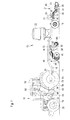
- FIG. 1 an agricultural working machine in the form of a tractor 18 with a drawn by the tractor 18 order combination 10 is shown.
- the order combination comprises a in the forward direction, which extends in the drawing from right to left, extending frame 12, which is supported by a wheels 14 comprehensive chassis on the ground.
- the frame 12 is verkuppelt via a drawbar 18 via a releasable coupling 20 with the tractor 18.
- the frame 12 carries in front of the wheels 14 a seed hopper 22 for receiving seed.
- a seed hopper 22 for receiving seed.
- the seed from the seed hopper 22 is measured and seed lines on the back of the frame 12 arranged seeding 24 supplied with a furrow opener 26 in the form of a disc, coulters 30, the seed in through the furrow opener Deliver 26 generated furrow and include closing wheels 28 for subsequent closing of the furrow.
- sowing devices 24 are supported laterally next to one another on a tool carrier 32 which is supported on the frame 12 and extends transversely to the forward direction.
- the sowing devices 24 are pivotally mounted about an axis extending parallel to the longitudinal axis of the tool carrier 32 axis.
- the pivoting angle of all sowing devices 24 and thus the sowing depth is determined by an actuator 34 in the form of a hydraulic cylinder, which is located between a with the frame 12 connected bracket 33 and coupled to the sowing devices 24 arm 35 extends.
- a support frame 36 is mounted below the frame 12.
- the support frame 36 supports a pivotable about a horizontal, transversely to the forward direction pivot axis 44 pivotable frame 38, on which a U-shaped spring 40, a soil working tool 42 is supported in the form of a disc harrow.
- An actuator 46 in the form of a hydraulic cylinder arranged between the frame 12 and swing frame 38 defines the pivoting angle of the swing frame 38 about the pivot axis 44.
- the actuator 46 is operable with adjustable pressure and thus controls the pressure with which the soil working tool 42 hits the ground acts. Instead of the disc harrow, any other tilling tool 42 may be used.
- a hinged about an axis parallel to the pivot axis 44 pivotable holder 48, at the lower end of a bottom roller 50 is mounted in the form of a tire packer.
- the actuator 52 is subjected to an adjustable pressure and controls in this way the pressure with which the bottom roller 42 the soil acts.
- U-shaped springs 40 are arranged at both lateral ends of the soil working tool 42 connected to the pivot frame 38 at both lateral ends of the soil working tool 42 connected to the pivot frame 38.
- brackets 48 are disposed on both lateral ends of the bottom roller 50 and connected to the support frame 36.
- the soil working tool 42 and the bottom roller 50 can be composed of three or more laterally juxtaposed sections, of which the exterior, in a conventional manner, can be folded up for road transport. For this purpose, appropriate drives in the form of hydraulic cylinders are to be provided.
- a harrow 66 is arranged, which is connected to the support frame 36.
- the order combination 10 represents after all a combination of a seeder with the seed hopper 22 and the sowing devices 24 on the one hand and a harrow with the soil working tool 42, the harrow 66 and the bottom roller 50 on the other hand.
- the tractor 18 is equipped with a control device 54 which is arranged over in the Drawing not shown lines the actuators 34, 46 and 52 by means of a preferably proportional valves containing valve means 56 from a source 58 pressurized hydraulic fluid to pressurize hydraulic fluid or relieve.
- the actuators 34, 46 and 52 are double-acting to lift the working elements of the order combination 10 in the headland or on a road trip.
- the control device 54 is thus set up to prescribe the pressure of the actuators 46 and 52.
- Information about the position of the actuator 34 is supplied to the control device 54 via a sensor 60, so that the sowing depth of the sowing devices 24 can be regulated by the control device 54 by means of the valve device 56.
- the valve device 56 may be located on board the tractor 18, as in the FIG. 1 In the second case, it would be connected to the control device 54 via a bus system, for example an ISO bus, which also establishes the connection between the control device 54 and the actuator 86 and the sensor 60.
- the control device 54 could also be arranged on board the order combination 10 and only the operator input device 68 positioned as a virtual terminal on board the tractor 18 and via a bus system with the controller 54 (and possibly with a further processing device of the tractor 18, the actuator 84 and the valve device 56 controlled).
- a speed sensor 74 detects the rotational speed of a front wheel 78 or rear wheel 80 of the tractor 18 and also supplies its signals to the control device 54.
- the speed of the tractor 18 above the ground may also be detected by a radar sensor 82.
- An actuator 84 in the form of a speed setting device is connected to the control device 54 and serves to set the forward speed of the tractor 18 by adjusting the speed of the drive motor of the tractor 18 and / or the gear ratio between the drive motor and the drivable wheels 78 and / or 80 ,
- An actuator 86 specifies the distance in which the sowing devices 24 deposit seed in the ground.
- the actuator 86 can serve, for example, to drive the measuring systems of the sowing devices 24 or to change their rotational speed.
- an operator input device 68 is attached to the workstation of the tractor 18, which is also connected to the control device 54.
- the control device 54 and the components connected to it including a memory device 64 are in the FIG. 2 shown schematically.
- the operator input device 68 allows the operator sitting in the tractor's cab 18 to input various working parameters of the order combination 10, namely the seeding depth (adjustment of the actuator 34 with feedback via the sensor 60), the bottom pressure of the bottom roller 50 (actuator 52) and the ground pressure the tillage tool 42 (actuator 46).
- the operator predefines the propulsion speed of the tractor 18 via a drive lever 70, which serves to actuate the actuator 84.
- the actuator 86 is also actuated in order to achieve a seed distance entered on the field with the operator input device 68.
- the tools are raised and lowered upon actuation of a second button of the headland input device 76 again.
- a processing device 88 is provided, which is connected to the control device 54 and detects the operating state of the tractor 18 and the order combination 10 and documented georeferenced over time.
- the processing device 88 is supplied by a position determination system 62 with a satellite receiving antenna, which is adapted to receive signals of the GPS (Global Positioning Systems), information containing information about the respective position of the tractor 18 signals.
- GPS Global Positioning Systems
- a bus line (not shown), which extends over the tractor 18 and preferably also on the order combination 10 and to which the control device 54, the processing device 88 and as a virtual terminal executed operator input device 68, and - as mentioned above - a controller (not shown) of the valve device 56 and the sensor 60 are connected.
- the positioning system 62, the headland input device 76, a sensor for detecting the position of the driving lever 70, the speed sensor 74 and / or the radar sensor 82, the actuator 84 and the actuator 86 (or their associated controller) can communicate with the control device via this bus line 54 communicate.
- the processing device 88 thus receives information directly and / or via the bus line and / or from the control unit 54 about the output of the position determination system 62, the signals of the sensors 70, 74, 82 and the desired state of the actuators 84 and 86 as input signals.
- the processing device 88 includes a merge module 90 in which input signals of different origin are merged together to reduce the amount of data and obtain more accurate data.
- the signals of the speed sensor 74, the radar sensor 82, the actuator 84 and the driving lever 70 may be fused together to obtain a more accurate signal about the speed of the tractor 18.
- DE 10 2010 031 344 A1 directed For this purpose and to provide any formatting data that may be required for the merger, reference is made to the disclosure of DE 10 2010 031 344 A1 directed.
- the merged data is then fed to a fuzzy classification 92 which associates the data with probabilities of falling into individual classes.
- a probability can be output for the following states: "detected idle”, “detected travel on a road”, “detected travel on the field”, “field work detected” and "detected unknown state”.
- This operating state may include, for example, the states “idle”, “on-road transport", “on-field transport” and "field work”.
- This detected operating state can be displayed to the operator on a display field of the operator input device 68. Additionally, it may be stored (e.g., for accounting purposes of a contractor) with the associated times, and / or may serve to drive components of the tractor 18 or the order combination 10, e.g. to stop the engine after a long idle period.
- the procedure described initially seems a bit cumbersome, because from some existing data, the operating state could be derived directly. For this, however, a complex, very machine-specific programming would be required, since a knowledge of the importance of the necessary data for detecting the operating state would be required.
- the processing device 88 according to the invention is distinguished by universal applicability without programming adapted to the respective machine. So a consideration of details of the order combination 10 is not required, which is why the Processing device 88 without reprogramming could also be used on a tractor with a syringe or a seeder. By HMM processing, the temporal dependence of the states can be further observed.
- step S102 follows, in which data for setting a model is evaluated.
- a model is determined that characterizes the respective operating mode of the tractor 18.
- the data used for this purpose can be derived via the bus line (in particular signals from the sensors 70, 74, 82 and the nominal state of the actuators 84 and 86), from the position determination system 62 or from other calculations (S104).
- Possible models would be eg "field work”, “road trip”, “maintenance”, “approaching headland”.
- the decision in favor of one of the models can be made, for example, by using the signals of the position determination system 62 and / or the speed sensor 74, using the signals of the position determination system 62 to determine the region and the country of the tractor insert (and, if applicable, specific country-specific practices in field work). and / or the position of the tractor 18 relative to the field boundaries can be derived. If present, the position of a switch for switching between road and field work can be detected, which can be integrated in the operator input device 68, for example. During maintenance work, a flap is typically open whose position can be detected, or it is detected whether the tractor 18 is steered automatically or manually.
- step S106 in which it is queried whether a new model should be used, which is decided on the basis of the previous model and the model determined in step S102. If a new model is needed, step S108 follows, in which, from a model database (S110), depending on the model determined in step S102, the state transition matrix A associated with the model and the input state ⁇ are read out.
- a model database S110
- step S108 is then followed by the step S112, in which the hidden Markov model 94, on the one hand, the external observations (step S114) are supplied, which come from the fuzzy classification 92.
- the step S114 may optionally use data from the step S104.
- data from a machine monitor commonly used for telemetric purposes to remotely monitor machine condition (control of engine speed, engine temperature, fuel consumption, etc.), sensor status monitoring, plausibility of sensors' output values, and / or operator monitoring using a camera in the cabin the activities and Inputs of the operator detected in step S114 and the step S112 are supplied. These data serve as observations for the hidden Markov model.
- these data are used to evaluate the respectively required elements of a column of the respectively used emission probability matrix B for the hidden Markov model online.
- the elements of the emission probability matrix B are thus not taken from a previously stored database, but evaluated on the basis of the current observations. This has the advantage that varying qualities of the sensors and uncertainties of the measured values can be taken into account, and also effects of sensor failures, temperature dependencies, overheating etc. can be compensated.
- the step S112 is also run through if the step S106 has revealed that no new model is to be used.
- Step S112 is followed by step S116, which is the forward step of a forward-backward algorithm for evaluating the hidden Markov model.
- step S118 is followed by step S118, in which a scaling of the state probabilities takes place, and step S120, in which the data obtained in step S118 are written into a stack.
- step S122 the conditions for the tracking step (backtracking) for the evaluation of the hidden Markov model are then calculated.
- step S122 it is determined, for example, whether there is still the same state as in the last run of step S122 (ie, all states have the same predecessor), if the stack is completely filled, if the tractor 18 is turned off, if there is traffic on the bus, if a Abort condition, or whether the model (step S106) has been changed, and whether there is sufficient data to distinguish between hidden states.
- the diagonal elements of the state transition matrix A which are in a state relative to the expected dwell time, may be used to determine the conditions for a backtracking step. If one or more of these conditions is met, step S124 proceeds to step S126, otherwise step S102 follows again. It is thus determined online in steps S122 and S124 whether the backtracking step S126 is performed or not, wherein one or more of the conditions mentioned in this paragraph is requested.
- step S126 the backtracking step is performed, followed by step S128 in which the state estimation results are stored in a memory.
- step S130 in which the stack is reset by turning its pointer is again placed on the first entry and optionally all described memory elements are overwritten, eg with the value 0 (zero).
- step S132 whether the loop is to be passed is checked again, and if so, step S102 follows, otherwise the end in step S134.
- step S128 may be followed by step S136 (instead of proceeding directly to step S130) in which the determined data (hidden Markov model, state, estimation and results) are stored and at least the determined operating state is stored on the display of the operator input device 68, for example are displayed.
- step 124 merely asks if the memory is full and / or there is an abort condition and / or the tractor is turned off, and then steps 126 and 102, respectively Viterbi algorithm (steps S116 and S126) is referred to the literature, in particular to the above-mentioned publication by L. Rabiner.
Landscapes
- Engineering & Computer Science (AREA)
- Physics & Mathematics (AREA)
- General Physics & Mathematics (AREA)
- Life Sciences & Earth Sciences (AREA)
- Data Mining & Analysis (AREA)
- Computational Mathematics (AREA)
- Theoretical Computer Science (AREA)
- Mathematical Physics (AREA)
- Pure & Applied Mathematics (AREA)
- Mathematical Analysis (AREA)
- Mathematical Optimization (AREA)
- Environmental Sciences (AREA)
- Soil Sciences (AREA)
- Mechanical Engineering (AREA)
- Operations Research (AREA)
- Probability & Statistics with Applications (AREA)
- Evolutionary Biology (AREA)
- Algebra (AREA)
- Bioinformatics & Computational Biology (AREA)
- Databases & Information Systems (AREA)
- Software Systems (AREA)
- General Engineering & Computer Science (AREA)
- Bioinformatics & Cheminformatics (AREA)
- Lifting Devices For Agricultural Implements (AREA)
- Management, Administration, Business Operations System, And Electronic Commerce (AREA)
- Component Parts Of Construction Machinery (AREA)
- Testing And Monitoring For Control Systems (AREA)
- Agricultural Machines (AREA)
Abstract
Description
- Die Erfindung betrifft eine Einrichtung zur Erfassung des Betriebszustands einer Arbeitsmaschine, umfassend:
- einen oder mehrere Sensoren zur Bereitstellung jeweils eines Ausgangswerts hinsichtlich eines aktuellen Parameters einer Komponente der Arbeitsmaschine,
- eine mit den Sensoren verbundene Verarbeitungseinheit, die programmiert ist, anhand des oder der Messwerte der Sensoren und/oder daraus abgeleiteter Werte unter Verwendung eines Hidden-Markov-Modells eine Information über den Betriebszustand der Arbeitsmaschine abzuleiten,
- wobei die Verarbeitungseinheit mit einer Zustandsübergangsmatrix A, Elementen einer Emissionswahrscheinlichkeitsmatrix B für die Wahrscheinlichkeit, dass eine Beobachtung durch einen bestimmten Zustand bedingt ist und einem Vektor π zur Beschreibung eines Eingangszustands beaufschlagbar ist, um daraus den Betriebszustand S der Arbeitsmaschine abzuleiten.
- Arbeitsmaschinen werden derzeit mit immer mehr Aktoren und Sensoren ausgestattet, die zum Antrieb beweglicher Elemente dienen. Dies trifft insbesondere für landwirtschaftliche Arbeitsmaschinen zu, wie selbstfahrende Erntemaschinen und Traktoren, die mit unterschiedlichen Zusatzausrüstungen betrieben werden können, wie Erntevorsätzen für Erntemaschinen oder gezogenen oder angebauten Geräten z.B. zur Bodenbearbeitung, zum Säen oder zur Ernte für Traktoren. Um dem Bediener oder einer beabstandeten Stelle eine Information darüber zu geben, ob alle Komponenten der Arbeitsmaschine korrekt arbeiten, und/oder zur selbsttätigen Ansteuerung von Komponenten basierend auf dem jeweiligen Betriebszustand der Arbeitsmaschine wurde vorgeschlagen (Sebastian Blank, Georg Kormann, Karsten Berns: A Modular Sensor Fusion Approach for Agricultural Machines, XXXVI CIOSTA & CIGR Section V Conference, Juni 2011 - Wien, im Internet veröffentlicht unter http://www.nas.boku.ac.at/fileadmin/_/H93/H931/CIOSTA_Presentations/Blank.pdf), den Betriebszustand der Arbeitsmaschine mittels einer Mehrzahl an Sensoren zu erfassen. Die Signale der Sensoren werden durch einen Sensorwissensmanager angeglichen und mittels eines Fusionsmoduls verschmolzen (fusioniert), um eine gegenüber den einzelnen Sensorwerten verminderte, jedoch genauere Datenmenge zu erzielen. Dann werden die fusionierten Daten einer Fuzzy-Klassifikation unterzogen und das Ergebnis dieser Klassifikation wird unter Verwendung eines Hidden-Markov-Modells (HMM) analysiert, um schließlich eine Information über den jeweiligen Betriebszustand der Arbeitsmaschine zu gewinnen. Dem Sensorwissensmanager werden aus einer Sensorwissens-Datenbank Informationen über die einzelnen Sensoren zugeführt, die zur Verschmelzung der Sensordaten benötigt werden. Dem Fusionsmodul und dem Hidden-Markov-Modell werden weiteres, statisches Domänenwissen hinsichtlich der Konfiguration der Arbeitsmaschine aus einer gemeinsam genutzten Datenbank zugeführt, die einerseits zur Ableitung einer Regelbasis für die Fuzzy-Klassifikation und andererseits zur Auswertung der Daten durch das Hidden-Markov-Modell dienen.
- Aus mathematischer Perspektive sind die HMMs eine Erweiterung normaler Markov-Ketten zur Überwindung der Beschränkung, dass jeder Übergangszustand mit einer physikalischen Beobachtung korrespondieren muss. Dieses Erfordernis beschränkt die Fälle, in denen ein temporäres probabilistisches Modell angewendet werden kann, beträchtlich. Zur Überwindung dieses Problems bestehen die HMM aus einer Struktur aus zwei verbundenen statistischen Prozessen, die ineinander eingebettet sind. Der erste, nicht beobachtbare Prozess ist eine Markovkette mit Zuständen und Übergangswahrscheinlichkeiten und der zweite, beobachtbare Prozess erzeugt zu jedem Zeitpunkt Emissionen, die auf dem derzeitigen, nicht beobachtbaren internen (ersten) Zustand basieren. Man verwendet den zweiten Prozess als Mittel zur Beobachtung des ersten Prozesses, der die weitestgehend unbekannte Struktur des unter Beobachtung befindlichen Prozesses emuliert.
- Das Hidden-Markov-Modell λ lässt sich standardmäßig durch folgende fünf Größen beschreiben: λ= λ (S, A, B, π, V). Dabei ist S eine Menge an Zuständen (s1 bis sN) eines Modells, A eine Zustandsübergangsmatrix mit Elementen aij, B eine Emissionswahrscheinlichkeitsmatrix mit Elementen bjk für die Wahrscheinlichkeit, dass die Beobachtung vk durch den Zustand sj bedingt ist, π ein Vektor zur Beschreibung eines Eingangszustands und V ein Beobachtungssymbolalphabet mit Elementen v1 bis vM. Basierend auf diesem Konzept kann eine Vielzahl an realen Problemen gehandhabt werden, die dadurch gekennzeichnet sind, dass ihre inneren Mechanismen teilweise nicht beobachtbar sind und somit nur stochastische Spezifikationen aus ihrem Verhalten abgeleitet werden können. Man leitet demnach den jeweiligen Zustand S des Modells aus der Beobachtung V ab, wozu der Eingangszustand π und die Matrizen A und B bekannt und insbesondere konstant (zeitlich invariant) sein müssen. Zu weiteren Details hierzu sei auf die Literatur verwiesen, z.B. L.R. Rabiner, A Tutorial on Hidden-Markov-Models and Selected Applications in Speech Recognition, Proc. IEEE Vol. 77 No. 2 (Feb. 1989), S. 257 ff.
- Im oben erwähnten Stand der Technik von Blank et al. werden die Zustandsübergangsmatrix A, die Emissionswahrscheinlichkeitsmatrix B und der Eingangszustand π aus der Datenbank für statisches Domänenwissen entnommen. Das bedeutet einerseits einen relativ hohen Aufwand für eine anfängliche Erstellung der Matrix und andererseits eine gewisse Anfälligkeit für Fehler und/oder Toleranzen von Sensoren, denn diese sind in der statischen, vorab definierten Emissionswahrscheinlichkeitsmatrix B nicht eingerechnet.
- Die der Erfindung zu Grunde liegende Aufgabe wird darin gesehen, eine Einrichtung zur Überwachung des Zustands einer Arbeitsmaschine und ein entsprechendes Verfahren dahingehend weiterzubilden, dass die erwähnten Nachteile des Standes der Technik nicht oder in einem verminderten Maße auftreten.
- Diese Aufgabe wird erfindungsgemäß durch die Lehre der Patentansprüche 1, 4 und 6 gelöst, wobei in den weiteren Patentansprüchen Merkmale aufgeführt sind, die die Lösung in vorteilhafter Weise weiterentwickeln.
- Eine Einrichtung zur Überwachung des Betriebszustands einer Arbeitsmaschine umfasst einen Sensor oder eine Mehrzahl an Sensoren zur Bereitstellung jeweils eines Ausgangswert hinsichtlich eines aktuellen Parameters einer Komponente der Arbeitsmaschine und eine mit den Sensor(en) verbundene Verarbeitungseinheit, die programmiert ist, anhand der Messwerte der Sensor(en) und/oder daraus abgeleiteter Werte unter Verwendung eines Hidden-Markov-Modells eine Information über den Betriebszustand der Arbeitsmaschine abzuleiten. Die Verarbeitungseinheit ist mit einer Zustandsübergangsmatrix A, Elementen einer Emissionswahrscheinlichkeitsmatrix B für die Wahrscheinlichkeit, dass eine Beobachtung durch einen bestimmten Zustand bedingt ist und einem Vektor π zur Beschreibung eines Eingangszustands beaufschlagbar, um anhand der der Messwerte der Sensor(en) und/oder daraus abgeleiteter Werte (d.h. der jeweiligen Beobachtung) den Betriebszustand S der Arbeitsmaschine abzuleiten. Die Verarbeitungseinheit ist programmiert, Elemente der Emissionswahrscheinlichkeitsmatrix B aus den Messwerten des Sensors bzw. der Sensoren abzuleiten.
- Die erfindungsgemäße Einrichtung ist demnach in der Lage, aus den Signalen des oder der Sensoren unter Verwendung eines Hidden-Markov-Modells abzuleiten, welchen Betriebszustand die Arbeitsmaschine gerade hat. Im Fall eines Traktors mit angebautem Bodenbearbeitungsgerät kann die Einrichtung somit beispielsweise feststellen, ob das Bodenbearbeitungsgerät gerade den Boden bearbeitet oder nicht. Außerdem kann die Einrichtung erkennen, wenn der Traktor mit ausgehobenem Bodenbearbeitungsgerät auf einer Straße fährt oder im Vorgewende wendet. Optional könnten quantitative Werte, wie Arbeitstiefe, bearbeitete Fläche, Kraftstoffverbrauch, Verschleiß der Bodenbearbeitungswerkzeuge etc. evaluiert und ausgegeben werden. Das Hidden-Markov-Modell benötigt, wie eingangs beschrieben, eine Zustandsübergangsmatrix A, eine Emissionswahrscheinlichkeitsmatrix B mit Elementen für die Wahrscheinlichkeit, dass eine Beobachtung durch einen bestimmten Zustand bedingt ist und einen Vektor π zur Beschreibung eines Eingangszustands. Die Emissionswahrscheinlichkeitsmatrix B enthält definitionsgemäß Elemente bjk für die Wahrscheinlichkeit, dass die Beobachtung vk durch den Zustand sj bedingt ist. Anstelle der bisherigen, fest abgespeicherten Emissionswahrscheinlichkeitsmatrix B wird gemäß der vorliegenden Erfindung vorgeschlagen, Elemente der Emissionswahrscheinlichkeitsmatrix B aus Messwerten des oder der Sensoren abzuleiten, d.h. die gemessenen Emissionen des zweiten Prozesses mit den unterschiedlichen Zuständen des ersten Prozesses zu verknüpfen oder zu korrelieren, um Elemente der Emissionswahrscheinlichkeitsmatrix B zu bestimmen.
- Auf diese Weise kann sich die Einrichtung selbsttätig an besondere Situationen, wie variierende Qualitäten der Sensordaten, Unsicherheiten der Messwerte oder Sensorfehler beispielsweise bei Überhitzung und Sensorausfälle anpassen.
- Vorzugsweise ist die Verarbeitungseinheit programmiert, die besagten Elemente der Emissionswahrscheinlichkeitsmatrix B ganz oder teilweise aus fuzzifizierten Messwerten von Sensoren abzuleiten, die dem Hidden-Markov-Modell als Beobachtung zuführbar sind. Es wäre aber auch eine beliebige andere Vorklassifizierung oder Vorverarbeitung der Sensorwerte möglich, wie Clustering-Ansätze, Support Vector Machines, neuronale Netze, oder probabilitische Ansätze. Zusätzlich oder alternativ kann die Verarbeitungseinheit die erwähnten Elemente der Emissionswahrscheinlichkeitsmatrix B ganz oder teilweise aus Messwerten von Überwachungssensoren zur Erfassung des Zustands von Sensoren und/oder zur Überwachung eines Bedieners ableiten.
- Nach einem zweiten Aspekt der Erfindung ist die Verarbeitungseinheit programmiert, ein Modell für die jeweilige Betriebsart der Arbeitsmaschine anhand von Messwerten von Sensoren und/oder eines Positionsbestimmungssystems auszuwählen oder zu bestimmen und die Zustandsübergangsmatrix A und den Vektor π anhand des ermittelten Modells aus einer Datenbank, in welcher unterschiedliche Zustandsübergangsmatrizen für unterschiedliche Betriebsarten der Arbeitsmaschine abgelegt sind, auszuwählen. Es werden demnach mehrere, unterschiedliche Zustandsübergangsmatrizen A und/oder Vektoren π in einer Datenbank abgespeichert und bei jedem Durchlauf einer Zustandsabschätzungsschleife entschieden, welche Zustandsübergangsmatrix A und/oder welcher Vektor π nun verwendet werden soll.
- Die Entscheidung hinsichtlich des Modells für die Betriebsart kann basierend auf den Signalen eines Positionsbestimmungssystems zur Feststellung des Landes und der Region (um festzustellen, welche landwirtschaftlichen Praktiken dort üblich sind) und/oder zur Bestimmung der Position der Arbeitsmaschine im Feld insbesondere zwecks Unterscheidung zwischen Vorgewende und eigentlichem Feldbetrieb erfolgen. Alternativ oder zusätzlich kann das Modell für die Betriebsart anhand der Position eines Schalters zum Umschalten zwischen Straßen- und Feldbetrieb erkannt werden, oder es wird erkannt, ob gerade eine Wartung der Arbeitsmaschine stattfindet. Auch kann festgestellt werden, ob sich ein Fahrer an Bord befindet oder nicht, oder ob die Arbeitsmaschine gerade selbsttätig gelenkt wird. Weiterhin können Elemente der Zustandsübergangsmatrix A online modifiziert werden. Diese Elemente werden demnach nicht direkt aus der statischen Datenbank entnommen, sondern erst während des Betriebs berechnet. So besteht die Möglichkeit, beim Annähern an das Vorgewende die Wahrscheinlichkeit für einen Wendevorgang zu vergrößern und die Wahrscheinlichkeit für eine Transportfahrt auf dem Feld zu verkleinern, was zu entsprechend ansteigenden bzw. absinkenden Wahrscheinlichkeiten in der Zustandsübergangsmatrix A führt. Es wird demnach nicht mehr nur ein einziges Modell für den Betriebszustand verwendet, sondern mehrere derartige Modelle gleichzeitig, denen jeweils Wahrscheinlichkeiten zugeordnet werden, und die Zustandsübergangsmatrix A und der Eingangszustand π werden entsprechend ausgewählt.
- Nach einem dritten Aspekt der Erfindung ist die Verarbeitungseinheit programmiert, einen Nachverfolgungsschritt zur Bestimmung des Betriebszustands der Arbeitsmaschine nur dann auszuführen, wenn seit einem vorherigen Nachverfolgungsschritt eine andere Zustandsübergangsmatrix A und/oder ein anderer Vektor π ausgewählt wurde und/oder eine hinreichende Datenmenge zur Unterscheidung unterschiedlicher Betriebszustände vorliegt.
- Insbesondere kann die Verarbeitungseinheit den Zeitpunkt des Nachverfolgungsschritts abhängig von den Diagonalelementen der Zustandsübergangsmatrix A bestimmen.
- In den Zeichnungen ist ein nachfolgend näher beschriebenes Ausführungsbeispiel der Erfindung dargestellt. Es zeigt:
- Fig. 1
- eine seitliche Ansicht einer landwirtschaftlichen Maschine in Form eines Traktors mit einer gezogenen Bestellkombination,
- Fig. 2
- ein Diagramm einer Steuereinrichtung mit den angeschlossenen Komponenten zur Kontrolle der Aktoren der Bestellkombination und einer Verarbeitungseinrichtung zur Erfassung des Betriebszustands des Traktors und der Bestellkombination, und
- Fig. 3
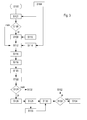
- ein Flussdiagramm, nach dem die Verarbeitungseinrichtung vorgeht.
- In der
Figur 1 ist eine landwirtschaftliche Arbeitsmaschine in Form eines Traktors 18 mit einer durch den Traktor 18 gezogenen Bestellkombination 10 dargestellt. Die Bestellkombination umfasst einen sich in der Vorwärtsrichtung, die in der Zeichnung von rechts nach links verläuft, erstreckenden Rahmen 12, der sich über ein Laufräder 14 umfassendes Fahrwerk auf dem Erdboden abstützt. An seinem vorderen Ende ist der Rahmen 12 über eine Deichsel 18 über eine lösbare Kupplung 20 mit dem Traktor 18 verkuppelt. - Der Rahmen 12 trägt vor den Laufrädern 14 einen Saatgutbehälter 22 zur Aufnahme von Saatgut. Durch, in der Zeichnung nicht dargestellte Messsysteme wird das Saatgut aus dem Saatgutbehälter 22 abgemessen und über Saatgutleitungen an der Rückseite des Rahmens 12 angeordneten Säeinrichtungen 24 zugeführt, die einen Furchenöffner 26 in Form einer Scheibe, Säschare 30, die das Saatgut in die durch den Furchenöffner 26 erzeugte Furche abgeben und Schließräder 28 zum anschließenden Schließen der Furche umfassen.
- Es sind mehrere Säeinrichtungen 24 seitlich nebeneinander an einem sich am Rahmen 12 abstützenden, sich quer zur Vorwärtsrichtung erstreckenden Werkzeugträger 32 abgestützt. Die Säeinrichtungen 24 sind um eine parallel zur Längsachse des Werkzeugträgers 32 verlaufende Achse schwenkbar gelagert. Der Schwenkwinkel aller Säeinrichtungen 24 und damit die Sätiefe wird durch einen Aktor 34 in Form eines Hydraulikzylinders festgelegt, der sich zwischen einer mit dem Rahmen 12 verbundenen Halterung 33 und einem mit den Säeinrichtungen 24 gekoppelten Arm 35 erstreckt.
- Vor dem Saatgutbehälter 22 ist unterhalb des Rahmens 12 ein Trägerrahmen 36 befestigt. Der Trägerrahmen 36 haltert einen um eine horizontale, quer zur Vorwärtsrichtung verlaufende Schwenkachse 44 schwenkbaren Schwenkrahmen 38, an dem sich über eine U-förmige Feder 40 ein Bodenbearbeitungswerkzeug 42 in Form einer Scheibenegge abstützt. Ein zwischen Rahmen 12 und Schwenkrahmen 38 angeordneter Aktor 46 in Form eines Hydraulikzylinders definiert den Schwenkwinkel des Schwenkrahmens 38 um die Schwenkachse 44. Der Aktor 46 ist mit einem einstellbaren Druck betreibbar und steuert auf diese Weise den Druck, mit dem das Bodenbearbeitungswerkzeug 42 auf den Erdboden einwirkt. Anstelle der Scheibenegge kann ein beliebiges anderes Bodenbearbeitungswerkzeug 42 verwendet werden.
- Am Trägerrahmen 36 ist weiterhin in Vorwärtsrichtung hinter dem Bodenbearbeitungswerkzeug 42 eine, um eine parallel zur Schwenkachse 44 verlaufende Achse schwenkbare Halterung 48 angelenkt, an deren unterem Ende eine Bodenwalze 50 in Form eines Reifenpackers angebracht ist. Ein Aktor 52 in Form eines Hydraulikzylinders, der sich zwischen dem Trägerrahmen 36 und der Halterung 48 erstreckt, definiert den Schwenkwinkel der Halterung 48. Der Aktor 52 ist mit einem einstellbaren Druck beaufschlagbar und steuert auf diese Weise den Druck, mit dem die Bodenwalze 42 auf den Erdboden einwirkt.
- An beiden seitlichen Enden des Bodenbearbeitungswerkzeugs 42 sind mit dem Schwenkrahmen 38 verbundene U-förmige Federn 40 angeordnet. Auch sind Halterungen 48 an beiden seitlichen Enden der Bodenwalze 50 angeordnet und mit dem Trägerrahmen 36 verbunden. Das Bodenbearbeitungswerkzeug 42 und die Bodenwalze 50 können sich aus drei oder mehr seitlich nebeneinander angeordneten Abschnitten zusammensetzen, von denen die Äußeren, in an sich bekannter Weise, zum Straßentransport hochklappbar sind. Dazu sind entsprechende Antriebe in Form von Hydraulikzylindern vorzusehen. Zwischen dem Bodenbearbeitungswerkzeug 42 und der Bodenwalze 50 ist ein Striegel 66 angeordnet, der mit dem Trägerrahmen 36 verbunden ist.
- Die Bestellkombination 10 stellt nach alledem eine Kombination aus einer Sämaschine mit dem Saatgutbehälter 22 und den Säeinrichtungen 24 einerseits und einem Bodenbearbeitungsgerät mit dem Bodenbearbeitungswerkzeug 42, dem Striegel 66 und der Bodenwalze 50 andererseits dar.
Der Traktor 18 ist mit einer Steuereinrichtung 54 ausgestattet, die eingerichtet ist, über in der Zeichnung nicht dargestellte Leitungen die Aktoren 34, 46 und 52 mittels einer vorzugsweise Proportionalventile enthaltenden Ventileinrichtung 56 aus einer Quelle 58 unter Druck stehenden Hydraulikfluids mit Hydraulikfluid zu beaufschlagen bzw. zu entlasten. In der dargestellten Ausführungsform sind die Aktoren 34, 46 und 52 doppeltwirkend, um die Arbeitselemente der Bestellkombination 10 im Vorgewende oder bei einer Straßenfahrt ausheben zu können. Denkbar wäre aber auch die Verwendung einfachwirkender Hydraulikzylinder. Die Steuereinrichtung 54 ist somit eingerichtet, den Druck der Aktoren 46 und 52 vorzugeben. Eine Information über die Position des Aktors 34 wird der Steuereinrichtung 54 über einen Fühler 60 zugeführt, so dass die Sätiefe der Säeinrichtungen 24 durch die Steuereinrichtung 54 mittels der Ventileinrichtung 56 regelbar ist. - Die Ventileinrichtung 56 kann sich an Bord des Traktors 18 befinden, wie in der
Figur 1 gezeigt, oder an Bord der Bestellkombination 18. Im zweiten Fall wäre sie mit der Steuereinrichtung 54 über ein Bussystem, z.B. einen ISO-Bus, verbunden, das auch die Verbindung zwischen der Steuereinrichtung 54 und dem Aktor 86 und dem Fühler 60 herstellt. Außerdem könnte auch die Steuereinrichtung 54 an Bord der Bestellkombination 10 angeordnet sein und nur die Bedienereingabeeinrichtung 68 als virtuelles Terminal an Bord des Traktors 18 positioniert und über ein Bussystem mit der Steuereinrichtung 54 (und ggf. mit einer weiteren Verarbeitungseinrichtung des Traktors 18, die den Aktor 84 und die Ventileinrichtung 56 kontrolliert) verbunden werden. - Ein Geschwindigkeitssensor 74 erfasst die Drehzahl eines vorderen Rades 78 oder rückwärtigen Rades 80 des Traktors 18 und führt seine Signale ebenfalls der Steuereinrichtung 54 zu. Die Geschwindigkeit des Traktors 18 über dem Erdboden kann auch mittels eines Radarsensors 82 erfasst werden.
- Ein Aktor 84 in Form einer Geschwindigkeitsvorgabeeinrichtung ist mit der Steuereinrichtung 54 verbunden und dient zur Vorgabe der Vorwärtsgeschwindigkeit des Traktors 18, indem er die Drehzahl des Antriebsmotors des Traktors 18 und/oder der Getriebeübersetzung zwischen dem Antriebsmotor und den antreibbaren Rädern 78 und/oder 80 verstellt. Ein Aktor 86 gibt den Abstand vor, in welchem die Säeinrichtungen 24 Saatgut im Erdboden ablegen. Der Aktor 86 kann beispielsweise zum Antrieb der Messsysteme der Säeinrichtungen 24 oder zur Veränderung von deren Drehzahl dienen.
- Schließlich ist am Arbeitsplatz des Traktors 18 noch eine Bedienereingabeeinrichtung 68 angebracht, die ebenfalls mit der Steuereinrichtung 54 verbunden ist. Die Steuereinrichtung 54 und die mit ihr verbundenen Komponenten einschließlich einer Speichereinrichtung 64 sind in der
Figur 2 schematisch dargestellt. Die Bedienereingabeeinrichtung 68 ermöglicht es dem in der Kabine des Traktors 18 sitzenden Bediener, verschiedene Arbeitsparameter der Bestellkombination 10 einzugeben, nämlich die Sätiefe (Verstellung des Aktors 34 mit Rückkopplung über den Fühler 60), den Bodendruck der Bodenwalze 50 (Aktor 52) und den Bodendruck des Bodenbearbeitungswerkzeugs 42 (Aktor 46). Der Bediener gibt die Vortriebsgeschwindigkeit des Traktors 18 über einen Fahrhebel 70 vor, der zur Ansteuerung des Aktors 84 dient. Abhängig von der jeweiligen Geschwindigkeitsvorgabe (Fahrhebel 70) oder der aktuellen Geschwindigkeit (Geschwindigkeitssensor 74 oder Radarsensor 82) wird auch der Aktor 86 angesteuert, um einen mit der Bedienereingabeeinrichtung 68 eingegebenen Abstand des Saatguts auf dem Feld zu erzielen. Das Ausheben der Werkzeuge der Bestellkombination 10 am Feldende mittels der Aktoren 34, 46, 52 erfolgt durch eine Vorgewendeeingabeeinrichtung 76 am Fahrhebel 70. Bei Betätigung einer ersten Taste der Vorgewendeeingabeeinrichtung 76 werden die Werkzeuge angehoben und bei Betätigung einer zweiten Taste der Vorgewendeeingabeeinrichtung 76 wieder abgesenkt. - Der Betrieb des Traktors 18 und der Bestellkombination 10 wird demnach bei der Feldarbeit manuell durch den Bediener in der Kabine des Traktors 18 gesteuert.
- Zur Dokumentation des Betriebs des Traktors 18 und der Bestellkombination 10 ist eine Verarbeitungseinrichtung 88 vorgesehen, die mit der Steuereinrichtung 54 verbunden ist und den Betriebszustand des Traktors 18 und der Bestellkombination 10 erfasst und über die Zeit georeferenziert dokumentiert. Der Verarbeitungseinrichtung 88 werden von einem Positionsbestimmungssystem 62 mit einer Satellitenempfangsantenne, die zum Empfang von Signalen des GPS (Global Positioning Systems) eingerichtet ist, eine Information über die jeweilige Position des Traktors 18 enthaltende Signale zugeführt. Die Verbindung zwischen der Verarbeitungseinrichtung 88 und der Steuereinrichtung 54 kann, wie in der
Figur 2 dargestellt, über eine separate Leitung erfolgen, oder sie erfolgt durch eine Bus-Leitung (nicht gezeigt), die sich über den Traktor 18 und vorzugsweise auch über die Bestellkombination 10 erstreckt und an welcher die Steuereinrichtung 54, die Verarbeitungseinrichtung 88 und die als virtuelles Terminal ausgeführte Bedienereingabeeinrichtung 68, sowie - wie oben erwähnt - ein Controller (nicht gezeigt) der Ventileinrichtung 56 und des Fühlers 60 angeschlossen sind. Auch das Positionsbestimmungssystem 62, die Vorgewendeeingabeeinrichtung 76, ein Sensor zur Erfassung der Position des Fahrhebels 70, der Geschwindigkeitssensor 74 und/oder der Radarsensor 82, der Aktor 84 und der Aktor 86 (bzw. ihnen zugeordnete Controller) können über diese Busleitung mit der Steuereinrichtung 54 kommunizieren. - Die Verarbeitungseinrichtung 88 erhält somit direkt und/oder über die Busleitung und/oder von der Steuereinheit 54 Informationen über die Ausgabe des Positionsbestimmungssystems 62, die Signale der Sensoren 70, 74, 82 und den Sollzustand der Aktoren 84 und 86 als Eingangssignale. Die Verarbeitungseinrichtung 88 umfasst ein Verschmelzungsmodul 90, in dem Eingangssignale unterschiedlicher Herkunft miteinander verschmolzen werden, um die Datenmenge zu reduzieren und genauere Daten zu erhalten. Beispielsweise können die Signale des Geschwindigkeitssensors 74, des Radarsensors 82, des Aktors 84 und des Fahrhebels 70 miteinander verschmolzen werden, um ein genaueres Signal über die Geschwindigkeit des Traktors 18 zu erhalten. Hierzu und zur Bereitstellung eventuell zur Verschmelzung erforderlicher Formatierungsdaten sei auf die Offenbarung der
DE 10 2010 031 344 A1 verwiesen. Die verschmolzenen Daten werden dann einer Fuzzy-Klassifizierung 92 zugeführt, welche den Daten Wahrscheinlichkeiten zuordnet, dass sie in einzelne Klassen fallen. So kann anhand des vom Verschmelzungsmodul 90 gelieferten Geschwindigkeitswerts und der Daten vom Positionserfassungssystem 62 jeweils eine Wahrscheinlichkeit für folgende Zustände ausgegeben werden: "erfasster Leerlauf", "erfasste Transportfahrt auf einer Straße", "erfasste Transportfahrt auf dem Feld", "erfasste Feldarbeit" und "erfasster unbekannter Zustand". - Diese Fuzzy-klassifizierten Wahrscheinlichkeiten werden dann einem Hidden-Markov-Modell 94 zugeführt, unter Verwendung dessen die Verarbeitungseinrichtung 88 aus diesen Wahrscheinlichkeiten den Betriebszustand des Traktors 18 und der Bestellkombination 10 ableitet. Dieser Betriebszustand kann beispielsweise die Zustände "Leerlauf", "Transport auf einer Straße", "Transport auf dem Feld" und "Feldarbeit" umfassen. Dieser erfasste Betriebszustand kann dem Bediener auf einem Anzeigefeld der Bedienereingabeeinrichtung 68 angezeigt werden. Zusätzlich kann er (z.B. für Abrechnungszwecke eines Lohnunternehmers) mit den zugehörigen Zeiten abgespeichert werden, und/oder er kann zur Ansteuerung von Komponenten des Traktors 18 oder der Bestellkombination 10 dienen, z.B. zum Abstellen des Motors nach längerem Leerlauf.
- Die beschriebene Vorgehensweise erscheint zunächst etwas umständlich, denn aus einigen vorliegenden Daten könnte der Betriebszustand direkt abgeleitet werden. Hierfür wäre aber eine aufwändige, sehr maschinenspezifische Programmierung erforderlich, da eine Kenntnis der Bedeutung der zur Erkennung des Betriebszustands notwendigen Daten erforderlich wäre. Die erfindungsgemäße Verarbeitungseinrichtung 88 zeichnet sich demgegenüber durch universelle Anwendbarkeit ohne an die jeweilige Maschine angepasste Programmierung aus. So ist eine Berücksichtigung von Details der Bestellkombination 10 nicht erforderlich, weshalb die Verarbeitungseinrichtung 88 ohne Neuprogrammierung auch an einem Traktor mit einer Spritze oder einer Sämaschine einsetzbar wäre. Durch die HMM-Verarbeitung kann weiterhin die zeitliche Abhängigkeit der Zustände beobachtet werden.
- Der Betrieb der Verarbeitungseinrichtung 88 erfolgt wie in der
Figur 3 dargestellt. Nach dem Start und der Initialisierung im Schritt S100 folgt der Schritt S102, in dem Daten für die Festlegung eines Modells evaluiert werden. Es wird somit ein Modell bestimmt, das die jeweilige Betriebsart des Traktors 18 charakterisiert. Die dafür verwendeten Daten können über die Busleitung (insbesondere Signale der Sensoren 70, 74, 82 und den Sollzustand der Aktoren 84 und 86), vom Positionsbestimmungssystem 62 oder aus anderen Berechnungen abgeleitet werden (S104). Mögliche Modelle wären z.B. "Feldarbeit", "Straßenfahrt", "Wartung", "Annäherung an Vorgewende". Die Entscheidung für eines der Modelle kann beispielsweise unter Verwendung der Signale des Positionsbestimmungssystems 62 und/oder des Geschwindigkeitssensors 74 erfolgen, wobei anhand der Signale des Positionsbestimmungssystems 62 die Region und das Land des Traktoreinsatzes (und daraus ggf. spezifische, ländertypische Vorgehensweisen bei der Feldarbeit) und/oder die Position des Traktors 18 gegenüber den Feldgrenzen abgeleitet werden können. Falls vorhanden, kann auch die Position eines Schalters zur Umschaltung zwischen Straßen- und Feldarbeit erfasst werden, der z.B. in der Bedienereingabeeinrichtung 68 integriert sein kann. Bei Wartungsarbeiten ist typischerweise eine Klappe geöffnet, deren Position erfasst werden kann, oder es wird erfasst, ob der Traktor 18 selbsttätig oder manuell gelenkt wird. - Es folgt der Schritt S106, in dem abgefragt wird, ob ein neues Modell verwendet werden soll, was anhand des bisherigen Modells und des im Schritt S102 bestimmten Modells entschieden wird. Wird ein neues Modell benötigt, folgt der Schritt S108, in dem aus einer Modelldatenbank (S110)- abhängig vom im Schritt S102 determinierten Modell - die dem Modell zugehörige Zustandsübergangsmatrix A und der Eingangszustand π ausgelesen werden.
- Auf den Schritt S108 folgt dann der Schritt S112, in welchem dem Hidden-Markov-Modell 94 einerseits die externen Beobachtungen (Schritt S114) zugeführt werden, die von der Fuzzy-Klassifizierung 92 stammen. Der Schritt S114 kann optional Daten aus dem Schritt S104 (mit-) verwenden. Zusätzlich können Daten von einer Maschinenüberwachung, wie sie üblicherweise für telemetrische Zwecke zur Fernüberwachung des Maschinenzustands verwendet wird (Kontrolle von Motordrehzahl, Motortemperatur, Kraftstoffverbrauch etc.), einer Sensorzustandsüberwachung, die Ausgangswerte der Sensoren auf Plausibilität überprüft, und/oder einer Bedienerüberwachung, die mit einer Kamera in der Kabine die Tätigkeiten und Eingaben des Bedieners erfasst, im Schritt S114 erfasst und dem Schritt S112 zugeführt werden. Diese Daten dienen dem Hidden-Markov-Modell als Beobachtungen. Andererseits werden diese Daten neuerungsgemäß dazu verwendet, die jeweils benötigten Elemente einer Spalte der jeweils verwendeten Emissionswahrscheinlichkeitsmatrix B für das Hidden-Markov-Modell online zu evaluieren. Die Elemente der Emissionswahrscheinlichkeitsmatrix B werden somit nicht aus einer vorab abgespeicherten Datenbank entnommen, sondern anhand der aktuellen Beobachtungen evaluiert. Das hat den Vorteil, dass variierenden Qualitäten der Sensoren und Unsicherheiten der Messwerte Rechnung getragen werden kann, auch können Auswirkungen von Sensorausfällen, Temperaturabhängigkeiten, Überhitzungen etc. ausgeglichen werden.
- Der Schritt S112 wird auch durchlaufen, wenn der Schritt S106 ergeben hat, dass kein neues Modell zu verwenden ist.
- Auf den Schritt S112 folgt der Schritt S116, bei dem es sich um den Vorwärtsschritt eines "Forward-Backward-Algorithmus" zur Auswertung des Hidden-Markov-Modells handelt. Es folgt der Schritt S118, in dem eine Skalierung der Zustandswahrscheinlichkeiten erfolgt, und der Schritt S120, in welchem die im Schritt S118 erhaltenen Daten in einen Stapelspeicher eingeschrieben werden. Im Schritt S122 werden dann die Bedingungen für den Nachverfolgungsschritt (Backtracking) zur Auswertung des Hidden-Markov-Modells berechnet. Es wird hierzu beispielsweise bestimmt, ob noch derselbe Zustand vorliegt wie beim letzten Durchlauf des Schritts S122 (d.h. alle Zustände denselben Vorgänger haben), ob der Stapelspeicher komplett gefüllt ist, ob der Traktor 18 ausgeschaltet ist, ob Datenverkehr auf der Busleitung vorliegt, ob eine Abbruchbedingung vorliegt, oder ob das Modell (Schritt S106) geändert wurde, und ob hinreichend Daten vorliegen, zwischen versteckten Zuständen zu unterscheiden. Weiterhin können die diagonalen Elemente der Zustandsübergangsmatrix A, die in Relation zur erwarteten Verweildauer in einem Zustand stehen, zur Bestimmung der Bedingungen für einen Nachverfolgungsschritt (Backtracking) verwendet werden. Ist eine oder mehrere dieser Bedingungen erfüllt, wird im nachfolgenden Schritt S124 auf den Schritt S126 weitergegangen, anderenfalls folgt wieder der Schritt S102. Es wird somit in den Schritten S122 und S124 online festgestellt, ob der Backtrackingschritt S126 durchgeführt wird oder nicht, wobei eine oder mehrere der in diesem Absatz erwähnten Konditionen abgefragt wird.
- Im Schritt S126 erfolgt der Nachverfolgungsschritt (Backtracking), gefolgt vom Schritt S128, in welchem die Zustandsabschätzungsergebnisse in einem Speicher abgelegt werden. Darauf folgt der Schritt S130, in dem der Stapelspeicher zurückgesetzt wird, indem dessen Zeiger wieder auf den ersten Eintrag gelegt wird und optional alle beschriebenen Speicherelemente überschrieben werden, z.B. mit dem Wert 0 (null). Dann wird im Schritt S132 abgefragt, ob die Schleife noch einmal durchlaufen werden soll, und wenn das der Fall ist, folgt der Schritt S102, anderenfalls das Ende im Schritt S134. Auf den Schritt S128 kann (anstelle gleich zum Schritt S130 zu gehen) der Schritt S136 folgen, in welchem die ermittelten Daten (Hidden-Markov-Modell, Zustand, Abschätzung und Ergebnisse) gespeichert und zumindest der ermittelte Betriebszustand z.B. auf der Anzeige der Bedienereingabeeinrichtung 68 angezeigt werden.
- Falls ein Stapelspeicher mit fester Größe verwendet wird, wird im Schritt 124 lediglich abgefragt, ob der Speicher voll ist und/oder eine Abbruchbedingung vorliegt und/oder der Traktor ausgeschaltet wird, und es folgt dann der Schritt 126 bzw. 102. Zu Details hinsichtlich des Viterbi-Algorithmus (Schritte S116 und S126) sei auf die Literatur verwiesen, insbesondere auf die eingangs erwähnte Veröffentlichung von L. Rabiner.
-
- S100
- Start, Initialisierung
- S102
- Daten zur Festlegung eines Modells evaluieren
- S104
- externe Daten (CAN, GPS, berechnete Daten)
- S106
- neues Modell ?
- S108
- Modellauswahl (Zustandsübergangsmatrix A und Eingangszustand π)
- S110
- Modelldatenbank für HMM
- S112
- Beobachtung empfangen und Elemente der Emissionswahrscheinlichkeitsmatrix B bestimmen
- S114
- externe Beobachtung (Ausgang von 92 etc.)
- S116
- Vorwärtschritt (Viterbi)
- S118
- Skalierung
- S120
- Stapelspeichereintrag
- S122
- Bedingungen für Backtracking berechnen
- S124
- Backtracking durchführen?
- S126
- Nachverfolgungschritt (Viterbi)
- S128
- Abschätzungsergebnisse in Speicher schreiben
- S130
- Stapelspeicher zurücksetzen
- S132
- Schleife wieder durchlaufen?
- S134
- Ende
- S136
- Datenspeicherung und Ausgabe
Claims (8)
- Einrichtung zur Erfassung des Betriebszustands einer Arbeitsmaschine (18, 10), umfassend:einen oder mehrere Sensoren (70, 74, 82) zur Bereitstellung jeweils eines Ausgangswerts hinsichtlich eines aktuellen Parameters einer Komponente der Arbeitsmaschine (18,10),und eine mit den Sensoren (70, 74, 82) verbundene Verarbeitungseinheit (88), die programmiert ist, anhand der Messwerte des oder der Sensoren (70, 74, 82) und/oder daraus abgeleiteter Werte unter Verwendung eines Hidden-Markov-Modells (94) eine Information über den Betriebszustand der Arbeitsmaschine (18, 10) abzuleiten,wobei die Verarbeitungseinheit (88) mit einer Zustandsübergangsmatrix A, Elementen einer Emissionswahrscheinlichkeitsmatrix B für die Wahrscheinlichkeit, dass eine Beobachtung durch einen bestimmten Zustand bedingt ist und einem Vektor π zur Beschreibung eines Eingangszustands beaufschlagbar ist, um daraus den Betriebszustand S der Arbeitsmaschine (18, 10) abzuleiten,dadurch gekennzeichnet, dass die Verarbeitungseinheit (88) programmiert ist, Elemente der Emissionswahrscheinlichkeitsmatrix B aus den Messwerten des oder der Sensoren (70, 74, 82) abzuleiten.
- Einrichtung nach Anspruch 1, wobei die Verarbeitungseinheit (88) programmiert ist, die Elemente der Emissionswahrscheinlichkeitsmatrix B aus fuzzifizierten Messwerten von Sensoren (70, 74, 82) abzuleiten, die dem Hidden-Markov-Modell (94) als Beobachtung zuführbar sind.
- Einrichtung nach Anspruch 1 oder 2, wobei die Verarbeitungseinheit (88) programmiert ist, die Elemente der Emissionswahrscheinlichkeitsmatrix B aus Messwerten einer Sensorzustandsüberwachung zur Erfassung des Zustands von Sensoren und/oder einer Einrichtung zur Überwachung eines Bedieners abzuleiten.
- Einrichtung zur Erfassung des Betriebszustands einer Arbeitsmaschine (18, 10), insbesondere nach einem der Ansprüche 1 bis 3, umfassend:einen oder mehrere Sensoren (70, 74, 82) zur Bereitstellung jeweils eines Ausgangswerts hinsichtlich eines aktuellen Parameters einer Komponente der Arbeitsmaschine (18,10),und eine mit den Sensoren (70, 74, 82) verbundene Verarbeitungseinheit (88), die programmiert ist, anhand der Messwerte des oder der Sensoren (70, 74, 82) und/oder daraus abgeleiteter Werte unter Verwendung eines Hidden-Markov-Modells (94) eine Information über den Betriebszustand der Arbeitsmaschine (18, 10) abzuleiten,wobei die Verarbeitungseinheit (88) mit einer Zustandsübergangsmatrix A, Elementen einer Emissionswahrscheinlichkeitsmatrix B für die Wahrscheinlichkeit, dass eine Beobachtung durch einen bestimmten Zustand bedingt ist und einem Vektor π zur Beschreibung eines Eingangszustands beaufschlagbar ist, um daraus den Betriebszustand S der Arbeitsmaschine (18, 10) abzuleiten,dadurch gekennzeichnet, dass die Verarbeitungseinheit (88) programmiert ist, ein Modell für die jeweilige Betriebsart der Arbeitsmaschine (18, 10) anhand von Messwerten von Sensoren (70, 74, 82) und/oder eines Positionsbestimmungssystems (62) zu bestimmen und die Zustandsübergangsmatrix A und/oder den Vektor π anhand des ermittelten Modells für die Betriebsart aus einer Datenbank, in welcher unterschiedliche Zustandsübergangsmatrizen A und/oder Vektoren π für unterschiedliche Betriebsarten der Arbeitsmaschine (18, 10) abgelegt sind, auszuwählen.
- Einrichtung nach Anspruch 4, wobei die Verarbeitungseinheit (88) programmiert ist, Elemente der Zustandsübergangsmatrix A während des Betriebs zu berechnen.
- Einrichtung zur Erfassung des Betriebszustands einer Arbeitsmaschine, insbesondere nach einem der Ansprüche 1 bis 5, umfassend:einen oder mehrere Sensoren (70, 74, 82) zur Bereitstellung jeweils eines Ausgangswerts hinsichtlich eines aktuellen Parameters einer Komponente der Arbeitsmaschine (18,10),und eine mit den Sensoren (70, 74, 82) verbundene Verarbeitungseinheit (88), die programmiert ist, anhand der Messwerte des oder der Sensoren (70, 74, 82) und/oder daraus abgeleiteter Werte unter Verwendung eines Hidden-Markov-Modells (94) eine Information über den Betriebszustand der Arbeitsmaschine (18, 10) abzuleiten,wobei die Verarbeitungseinheit (88) mit einer Zustandsübergangsmatrix A, Elementen einer Emissionswahrscheinlichkeitsmatrix B für die Wahrscheinlichkeit, dass eine Beobachtung durch einen bestimmten Zustand bedingt ist und einem Vektor π zur Beschreibung eines Eingangszustands beaufschlagbar ist, um daraus den Betriebszustand S der Arbeitsmaschine (18, 10) abzuleiten,dadurch gekennzeichnet, dass die Verarbeitungseinheit (88) programmiert ist, einen Nachverfolgungsschritt zur Bestimmung des Betriebszustands der Arbeitsmaschine (18, 10) nur dann auszuführen, wenn seit einem vorherigen Nachverfolgungsschritt eine andere Zustandsübergangsmatrix A und/oder ein anderer Vektor π ausgewählt wurde und/oder eine hinreichende Datenmenge zur Unterscheidung unterschiedlicher Betriebszustände vorliegt und/oder eine Änderung des Betriebszustands zu erwarten ist.
- Einrichtung nach Anspruch 6, wobei die Verarbeitungseinheit (88) programmiert ist, den Zeitpunkt des Nachverfolgungsschritts abhängig von den Diagonalelementen der Zustandsübergangsmatrix A zu bestimmen.
- Arbeitsmaschine (18, 10), insbesondere landwirtschaftliche Arbeitsmaschine z.B. in Form eines Traktors (18) mit einem Arbeitsgerät (10) oder in Form einer Erntemaschine, mit einer Einrichtung nach einem der vorhergehenden Ansprüche.
Applications Claiming Priority (1)
| Application Number | Priority Date | Filing Date | Title |
|---|---|---|---|
| DE102012220109.2A DE102012220109A1 (de) | 2012-11-05 | 2012-11-05 | Einrichtung zur Erfassung des Betriebszustands einer Arbeitsmaschine |
Publications (3)
| Publication Number | Publication Date |
|---|---|
| EP2752106A2 true EP2752106A2 (de) | 2014-07-09 |
| EP2752106A3 EP2752106A3 (de) | 2018-01-03 |
| EP2752106B1 EP2752106B1 (de) | 2021-10-27 |
Family
ID=49378144
Family Applications (1)
| Application Number | Title | Priority Date | Filing Date |
|---|---|---|---|
| EP13188825.7A Active EP2752106B1 (de) | 2012-11-05 | 2013-10-16 | Einrichtung zur Ableitung des Betriebszustands einer landwirtschaftlichen Arbeitsmaschine |
Country Status (4)
| Country | Link |
|---|---|
| US (1) | US10318609B2 (de) |
| EP (1) | EP2752106B1 (de) |
| AU (1) | AU2013251266B2 (de) |
| DE (1) | DE102012220109A1 (de) |
Cited By (2)
| Publication number | Priority date | Publication date | Assignee | Title |
|---|---|---|---|---|
| EP3438914A1 (de) | 2017-08-03 | 2019-02-06 | RAFI GmbH & Co. KG | Nutzfahrzeuge und verfahren zur erfassung von arbeitsabläufen, insbesondere bei nutzfahrzeugen sowie überwachungseinrichtung |
| CN110689642A (zh) * | 2019-09-18 | 2020-01-14 | 山东大学 | 基于车载obd数据及概率统计的异常驾驶判别方法及系统 |
Families Citing this family (73)
| Publication number | Priority date | Publication date | Assignee | Title |
|---|---|---|---|---|
| DE102013208320A1 (de) | 2013-05-07 | 2014-11-13 | Deere & Company | Verfahren zur Bestimmung eines Kontrollparameters eines Leistungs- oder Drehmomentverteilungsreglers für einen Hybridantrieb einer Arbeitsmaschine |
| DE102013221757B4 (de) | 2013-10-25 | 2024-07-04 | Deere & Company | Einrichtung und Verfahren zur Analyse und/oder Dokumentation des Betriebs eines Arbeitsfahrzeugs |
| AU2014203829A1 (en) * | 2014-07-11 | 2016-01-28 | Caterpillar Of Australia Pty Ltd | System and method for determining machine operational state |
| US9807932B2 (en) | 2015-10-02 | 2017-11-07 | Deere & Company | Probabilistic control of an agricultural machine |
| JP6823500B2 (ja) * | 2017-03-03 | 2021-02-03 | 株式会社小松製作所 | 作業車両および制御方法 |
| WO2018175641A1 (en) * | 2017-03-21 | 2018-09-27 | Blue River Technology Inc. | Combine harvester including machine feedback control |
| US11096323B2 (en) * | 2017-04-18 | 2021-08-24 | CropZilla Software, Inc. | Machine control system providing actionable management information and insight using agricultural telematics |
| DE102017210054A1 (de) | 2017-06-14 | 2018-12-20 | Deere & Company | Landwirtschaftliches Arbeitsfahrzeug mit Mitteln zur optimierten Positionierung einer an einer verstellbaren Schnittstelle angebrachten Last für eine Straßenfahrt |
| US10813269B2 (en) | 2018-08-24 | 2020-10-27 | Cnh Industrial America Llc | System and method for remotely controlling hydraulic components of an agricultural implement |
| US11178818B2 (en) * | 2018-10-26 | 2021-11-23 | Deere & Company | Harvesting machine control system with fill level processing based on yield data |
| US11079725B2 (en) | 2019-04-10 | 2021-08-03 | Deere & Company | Machine control using real-time model |
| US11957072B2 (en) | 2020-02-06 | 2024-04-16 | Deere & Company | Pre-emergence weed detection and mitigation system |
| US11672203B2 (en) | 2018-10-26 | 2023-06-13 | Deere & Company | Predictive map generation and control |
| US11653588B2 (en) | 2018-10-26 | 2023-05-23 | Deere & Company | Yield map generation and control system |
| US11641800B2 (en) | 2020-02-06 | 2023-05-09 | Deere & Company | Agricultural harvesting machine with pre-emergence weed detection and mitigation system |
| US11240961B2 (en) | 2018-10-26 | 2022-02-08 | Deere & Company | Controlling a harvesting machine based on a geo-spatial representation indicating where the harvesting machine is likely to reach capacity |
| US11467605B2 (en) | 2019-04-10 | 2022-10-11 | Deere & Company | Zonal machine control |
| US11589509B2 (en) | 2018-10-26 | 2023-02-28 | Deere & Company | Predictive machine characteristic map generation and control system |
| US12069978B2 (en) | 2018-10-26 | 2024-08-27 | Deere & Company | Predictive environmental characteristic map generation and control system |
| US11234366B2 (en) | 2019-04-10 | 2022-02-01 | Deere & Company | Image selection for machine control |
| US11778945B2 (en) | 2019-04-10 | 2023-10-10 | Deere & Company | Machine control using real-time model |
| CN110674752B (zh) * | 2019-09-25 | 2023-06-20 | 广东省智能机器人研究院 | 一种基于隐马尔可夫模型的刀具磨损状态识别与预测方法 |
| US11599814B2 (en) * | 2019-10-21 | 2023-03-07 | Microsoft Technology Licensing, Llc | Automated exception featurization and search |
| US12035648B2 (en) | 2020-02-06 | 2024-07-16 | Deere & Company | Predictive weed map generation and control system |
| US12225846B2 (en) | 2020-02-06 | 2025-02-18 | Deere & Company | Machine control using a predictive map |
| US12329148B2 (en) | 2020-02-06 | 2025-06-17 | Deere & Company | Predictive weed map and material application machine control |
| US12016257B2 (en) | 2020-02-19 | 2024-06-25 | Sabanto, Inc. | Methods for detecting and clearing debris from planter gauge wheels, closing wheels and seed tubes |
| US11477940B2 (en) | 2020-03-26 | 2022-10-25 | Deere & Company | Mobile work machine control based on zone parameter modification |
| US12461083B2 (en) | 2020-08-03 | 2025-11-04 | Sabanto, Inc. | Methods for improved agricultural procedures |
| US12252095B2 (en) * | 2020-08-25 | 2025-03-18 | Deere & Company | Work vehicle, door state determination system, and method of determining state of work vehicle door |
| US12069986B2 (en) | 2020-10-09 | 2024-08-27 | Deere & Company | Map generation and control system |
| US11889788B2 (en) | 2020-10-09 | 2024-02-06 | Deere & Company | Predictive biomass map generation and control |
| US11474523B2 (en) | 2020-10-09 | 2022-10-18 | Deere & Company | Machine control using a predictive speed map |
| US11864483B2 (en) | 2020-10-09 | 2024-01-09 | Deere & Company | Predictive map generation and control system |
| US12419220B2 (en) | 2020-10-09 | 2025-09-23 | Deere & Company | Predictive map generation and control system |
| US11635765B2 (en) | 2020-10-09 | 2023-04-25 | Deere & Company | Crop state map generation and control system |
| US12013245B2 (en) | 2020-10-09 | 2024-06-18 | Deere & Company | Predictive map generation and control system |
| US11711995B2 (en) | 2020-10-09 | 2023-08-01 | Deere & Company | Machine control using a predictive map |
| US11983009B2 (en) | 2020-10-09 | 2024-05-14 | Deere & Company | Map generation and control system |
| US11650587B2 (en) | 2020-10-09 | 2023-05-16 | Deere & Company | Predictive power map generation and control system |
| US11946747B2 (en) | 2020-10-09 | 2024-04-02 | Deere & Company | Crop constituent map generation and control system |
| US12178158B2 (en) | 2020-10-09 | 2024-12-31 | Deere & Company | Predictive map generation and control system for an agricultural work machine |
| US12386354B2 (en) | 2020-10-09 | 2025-08-12 | Deere & Company | Predictive power map generation and control system |
| US11927459B2 (en) | 2020-10-09 | 2024-03-12 | Deere & Company | Machine control using a predictive map |
| US11871697B2 (en) | 2020-10-09 | 2024-01-16 | Deere & Company | Crop moisture map generation and control system |
| US11845449B2 (en) | 2020-10-09 | 2023-12-19 | Deere & Company | Map generation and control system |
| US11849671B2 (en) | 2020-10-09 | 2023-12-26 | Deere & Company | Crop state map generation and control system |
| US12422847B2 (en) | 2020-10-09 | 2025-09-23 | Deere & Company | Predictive agricultural model and map generation |
| US12550802B2 (en) | 2020-10-08 | 2026-02-17 | Deere & Company | Predictive machine characteristic map generation and control system |
| US11675354B2 (en) | 2020-10-09 | 2023-06-13 | Deere & Company | Machine control using a predictive map |
| US11844311B2 (en) | 2020-10-09 | 2023-12-19 | Deere & Company | Machine control using a predictive map |
| US11727680B2 (en) | 2020-10-09 | 2023-08-15 | Deere & Company | Predictive map generation based on seeding characteristics and control |
| US11874669B2 (en) | 2020-10-09 | 2024-01-16 | Deere & Company | Map generation and control system |
| US11895948B2 (en) | 2020-10-09 | 2024-02-13 | Deere & Company | Predictive map generation and control based on soil properties |
| US11849672B2 (en) | 2020-10-09 | 2023-12-26 | Deere & Company | Machine control using a predictive map |
| US11592822B2 (en) | 2020-10-09 | 2023-02-28 | Deere & Company | Machine control using a predictive map |
| US12250905B2 (en) | 2020-10-09 | 2025-03-18 | Deere & Company | Machine control using a predictive map |
| US11889787B2 (en) | 2020-10-09 | 2024-02-06 | Deere & Company | Predictive speed map generation and control system |
| US12127500B2 (en) | 2021-01-27 | 2024-10-29 | Deere & Company | Machine control using a map with regime zones |
| US12229886B2 (en) | 2021-10-01 | 2025-02-18 | Deere & Company | Historical crop state model, predictive crop state map generation and control system |
| US12310286B2 (en) | 2021-12-14 | 2025-05-27 | Deere & Company | Crop constituent sensing |
| US12302791B2 (en) | 2021-12-20 | 2025-05-20 | Deere & Company | Crop constituents, predictive mapping, and agricultural harvester control |
| US12245549B2 (en) | 2022-01-11 | 2025-03-11 | Deere & Company | Predictive response map generation and control system |
| US12082531B2 (en) | 2022-01-26 | 2024-09-10 | Deere & Company | Systems and methods for predicting material dynamics |
| US12520759B2 (en) | 2022-01-26 | 2026-01-13 | Deere & Company | Systems and methods for predicting material dynamics |
| US12295288B2 (en) | 2022-04-05 | 2025-05-13 | Deere &Company | Predictive machine setting map generation and control system |
| US12058951B2 (en) | 2022-04-08 | 2024-08-13 | Deere & Company | Predictive nutrient map and control |
| US12284934B2 (en) | 2022-04-08 | 2025-04-29 | Deere & Company | Systems and methods for predictive tractive characteristics and control |
| US12298767B2 (en) | 2022-04-08 | 2025-05-13 | Deere & Company | Predictive material consumption map and control |
| US12582035B2 (en) | 2022-04-08 | 2026-03-24 | Deere & Company | Systems and methods for predictive power requirements and control |
| US12358493B2 (en) | 2022-04-08 | 2025-07-15 | Deere & Company | Systems and methods for predictive power requirements and control |
| DE102024113633A1 (de) * | 2024-05-15 | 2025-11-20 | Amazonen-Werke H. Dreyer SE & Co. KG | Landwirtschaftliche Arbeitsmaschine und Verfahren zum Betreiben einer landwirtschaftlichen Arbeitsmaschine |
| DE102024113625A1 (de) * | 2024-05-15 | 2025-11-20 | Amazonen-Werke H. Dreyer SE & Co. KG | Landwirtschaftliche Arbeitsmaschine und Verfahren zum Betreiben einer landwirtschaftlichen Arbeitsmaschine |
Citations (1)
| Publication number | Priority date | Publication date | Assignee | Title |
|---|---|---|---|---|
| DE102010031344A1 (de) | 2010-07-14 | 2012-01-12 | Deere & Company | System zur Kontrolle einer Arbeitsmaschine |
Family Cites Families (9)
| Publication number | Priority date | Publication date | Assignee | Title |
|---|---|---|---|---|
| US7421321B2 (en) * | 1995-06-07 | 2008-09-02 | Automotive Technologies International, Inc. | System for obtaining vehicular information |
| EP1533524B1 (de) * | 2002-08-26 | 2011-11-02 | Hitachi Construction Machinery Co., Ltd. | Signalverarbeitungsvorrichtung für baumaschinen |
| WO2009096519A1 (ja) * | 2008-01-31 | 2009-08-06 | Nec Corporation | フィードフォーワード制御方法、サービス提供品質制御装置、システム、プログラム及びその記録媒体 |
| US8612107B2 (en) * | 2008-06-10 | 2013-12-17 | The Regents Of The University Of Michigan | Method, control apparatus and powertrain system controller for real-time, self-learning control based on individual operating style |
| JP5215204B2 (ja) * | 2009-01-29 | 2013-06-19 | 株式会社クボタ | 作業機の表示構造 |
| US8344897B2 (en) * | 2009-10-12 | 2013-01-01 | Agco Corporation | System and method for assisting in the refilling of agricultural vehicles |
| JP5503955B2 (ja) * | 2009-12-14 | 2014-05-28 | 日立建機株式会社 | 作業車両の変速制御装置 |
| AU2011265563B2 (en) | 2010-12-24 | 2016-09-22 | Commonwealth Scientific And Industrial Research Organisation | System and method for detecting and/or diagnosing faults in multi-variable systems |
| US20130229272A1 (en) * | 2012-03-05 | 2013-09-05 | Caterpillar Inc. | Manual control device and method |
-
2012
- 2012-11-05 DE DE102012220109.2A patent/DE102012220109A1/de not_active Ceased
-
2013
- 2013-10-08 US US14/048,235 patent/US10318609B2/en active Active
- 2013-10-16 EP EP13188825.7A patent/EP2752106B1/de active Active
- 2013-11-01 AU AU2013251266A patent/AU2013251266B2/en active Active
Patent Citations (1)
| Publication number | Priority date | Publication date | Assignee | Title |
|---|---|---|---|---|
| DE102010031344A1 (de) | 2010-07-14 | 2012-01-12 | Deere & Company | System zur Kontrolle einer Arbeitsmaschine |
Non-Patent Citations (2)
| Title |
|---|
| L.R. RABINER: "A Tutorial on Hidden-Markov-Models and Selected Applications in Speech Recognition", PROC. IEEE, vol. 77, no. 2, February 1989 (1989-02-01), pages 257 FF, XP002550447, DOI: doi:10.1109/5.18626 |
| SEBASTIAN BLANK; GEORG KORMANN; KARSTEN BERNS, A MODULAR SENSOR FUSION APPROACH FOR AGRICULTURAL MACHINES, XXXVI CIOSTA & CIGR SECTION V CONFERENCE, June 2011 (2011-06-01) |
Cited By (2)
| Publication number | Priority date | Publication date | Assignee | Title |
|---|---|---|---|---|
| EP3438914A1 (de) | 2017-08-03 | 2019-02-06 | RAFI GmbH & Co. KG | Nutzfahrzeuge und verfahren zur erfassung von arbeitsabläufen, insbesondere bei nutzfahrzeugen sowie überwachungseinrichtung |
| CN110689642A (zh) * | 2019-09-18 | 2020-01-14 | 山东大学 | 基于车载obd数据及概率统计的异常驾驶判别方法及系统 |
Also Published As
| Publication number | Publication date |
|---|---|
| DE102012220109A1 (de) | 2014-05-08 |
| US20140129192A1 (en) | 2014-05-08 |
| AU2013251266B2 (en) | 2017-03-30 |
| EP2752106A3 (de) | 2018-01-03 |
| AU2013251266A1 (en) | 2014-05-22 |
| US10318609B2 (en) | 2019-06-11 |
| EP2752106B1 (de) | 2021-10-27 |
Similar Documents
| Publication | Publication Date | Title |
|---|---|---|
| EP2752106B1 (de) | Einrichtung zur Ableitung des Betriebszustands einer landwirtschaftlichen Arbeitsmaschine | |
| EP3381281B1 (de) | Verfahren und vorrichtung zur bekämpfung unerwünschter lebewesen auf einem feld | |
| EP2402213B1 (de) | Anordnung zur Kontrolle der Arbeitsgerätebeleuchtung eines Arbeitsfahrzeugs | |
| EP3289847B2 (de) | Anordnung zur beeinflussung der lage eines landwirtschaftlichen anbaugeräts | |
| DE102017222403A1 (de) | Verfahren und Vorrichtung zur Kartierung eventuell in einem Feld vorhandener Fremdkörper | |
| EP2622955A1 (de) | Landwirtschaftliche Maschine mit einem System zur selbsttätigen Einstellung eines Bearbeitungsparameters und zugehöriges Verfahren | |
| WO2020074043A1 (de) | Nachrüstkit zum anbau an ein landwirtschaftliches gerät | |
| EP1273215A1 (de) | Landwirtschaftliche Bestellkombination | |
| EP3756433B1 (de) | System zur kontrolle eines mit einem fahrzeug verbundenen arbeitsgeräts | |
| DE102011120884A1 (de) | Datenkommunikationseinheit und Verfahren zur Identifikation eines mit einer landwirtschaftlichen Zugmaschine koppelbaren landwirtschaftlichen Arbeitsgerätes | |
| EP2921050B1 (de) | Verfahren zum ausbringen von pflanzenschutzmitteln | |
| DE102014202181A1 (de) | Einrichtung und Verfahren zur Erkennung und Charakterisierung von Wendemanövern eines Arbeitsfahrzeugs | |
| DE102013221757B4 (de) | Einrichtung und Verfahren zur Analyse und/oder Dokumentation des Betriebs eines Arbeitsfahrzeugs | |
| EP3400769B1 (de) | Landwirtschaftliche arbeitsmaschine sowie verfahren zum betreiben einer landwirtschaftlichen arbeitsmaschine | |
| DE102019111317A1 (de) | Autonome landwirtschaftliche Arbeitsmaschine und Verfahren zu deren Betrieb | |
| EP4449862B1 (de) | Verfahren und anordnung zum betreiben eines landwirtschaftlichen verteilfahrzeugs | |
| DE102021208343B3 (de) | Autonom fahrendes Fahrzeug zum Befahren eines unbefestigten Geländeabschnittes, computer-implementiertes Ansteuerverfahren zum Ansteuern eines autonom fahrenden Fahrzeuges, sowie Computerprogrammprodukt | |
| EP4133925B1 (de) | Verfahren für den betrieb eines landwirtschaftlichen gespanns | |
| DE102023136337A1 (de) | Landwirtschaftliche Maschine und Verfahren zum Ausführen von Maschinenfunktionen | |
| DE102022115392A1 (de) | Kontrollanordnung zur selbsttätigen Steuerung einer landwirtschaftlichen Arbeitsmaschine, Arbeitsmaschine und Verfahren | |
| EP3364265A1 (de) | Verfahren zum steuern eines von einer zugmaschine gezogenen landwirtschaftlichen arbeitsgeräts | |
| EP3311639A1 (de) | Verfahren zur berechnung charakteristischer geometrie- und/oder stellgrössen eines dreipunkt-krafthebers | |
| DE102018213644A1 (de) | Steuereinrichtung für eine mittels Rädern bewegliche Arbeitsmaschine insbesondere landwirtschaftliche Arbeitsmaschine zur Einwirkung auf Pflanzen und Verfahren zur Steuerung | |
| DE102023133944A1 (de) | Verfahren zum Betreiben eines landwirtschaftlichen Gespanns | |
| DE102024136979A1 (de) | Verfahren zur automatischen verzögerungskompensation bei der arbeitsgerätesteuerung mit arbeitsmaschine |
Legal Events
| Date | Code | Title | Description |
|---|---|---|---|
| 17P | Request for examination filed |
Effective date: 20131016 |
|
| AK | Designated contracting states |
Kind code of ref document: A2 Designated state(s): AL AT BE BG CH CY CZ DE DK EE ES FI FR GB GR HR HU IE IS IT LI LT LU LV MC MK MT NL NO PL PT RO RS SE SI SK SM TR |
|
| AX | Request for extension of the european patent |
Extension state: BA ME |
|
| PUAI | Public reference made under article 153(3) epc to a published international application that has entered the european phase |
Free format text: ORIGINAL CODE: 0009012 |
|
| REG | Reference to a national code |
Ref country code: DE Ref legal event code: R079 Ref document number: 502013015964 Country of ref document: DE Free format text: PREVIOUS MAIN CLASS: A01D0041127000 Ipc: G07C0005080000 |
|
| PUAL | Search report despatched |
Free format text: ORIGINAL CODE: 0009013 |
|
| AK | Designated contracting states |
Kind code of ref document: A3 Designated state(s): AL AT BE BG CH CY CZ DE DK EE ES FI FR GB GR HR HU IE IS IT LI LT LU LV MC MK MT NL NO PL PT RO RS SE SI SK SM TR |
|
| AX | Request for extension of the european patent |
Extension state: BA ME |
|
| RIC1 | Information provided on ipc code assigned before grant |
Ipc: G07C 5/08 20060101AFI20171127BHEP Ipc: A01B 76/00 20060101ALI20171127BHEP |
|
| STAA | Information on the status of an ep patent application or granted ep patent |
Free format text: STATUS: REQUEST FOR EXAMINATION WAS MADE |
|
| R17P | Request for examination filed (corrected) |
Effective date: 20180703 |
|
| RBV | Designated contracting states (corrected) |
Designated state(s): AL AT BE BG CH CY CZ DE DK EE ES FI FR GB GR HR HU IE IS IT LI LT LU LV MC MK MT NL NO PL PT RO RS SE SI SK SM TR |
|
| STAA | Information on the status of an ep patent application or granted ep patent |
Free format text: STATUS: EXAMINATION IS IN PROGRESS |
|
| 17Q | First examination report despatched |
Effective date: 20200219 |
|
| GRAP | Despatch of communication of intention to grant a patent |
Free format text: ORIGINAL CODE: EPIDOSNIGR1 |
|
| STAA | Information on the status of an ep patent application or granted ep patent |
Free format text: STATUS: GRANT OF PATENT IS INTENDED |
|
| INTG | Intention to grant announced |
Effective date: 20210610 |
|
| GRAS | Grant fee paid |
Free format text: ORIGINAL CODE: EPIDOSNIGR3 |
|
| GRAA | (expected) grant |
Free format text: ORIGINAL CODE: 0009210 |
|
| STAA | Information on the status of an ep patent application or granted ep patent |
Free format text: STATUS: THE PATENT HAS BEEN GRANTED |
|
| AK | Designated contracting states |
Kind code of ref document: B1 Designated state(s): AL AT BE BG CH CY CZ DE DK EE ES FI FR GB GR HR HU IE IS IT LI LT LU LV MC MK MT NL NO PL PT RO RS SE SI SK SM TR |
|
| REG | Reference to a national code |
Ref country code: GB Ref legal event code: FG4D Free format text: NOT ENGLISH |
|
| REG | Reference to a national code |
Ref country code: CH Ref legal event code: EP |
|
| REG | Reference to a national code |
Ref country code: AT Ref legal event code: REF Ref document number: 1442514 Country of ref document: AT Kind code of ref document: T Effective date: 20211115 |
|
| REG | Reference to a national code |
Ref country code: DE Ref legal event code: R096 Ref document number: 502013015964 Country of ref document: DE |
|
| REG | Reference to a national code |
Ref country code: IE Ref legal event code: FG4D Free format text: LANGUAGE OF EP DOCUMENT: GERMAN |
|
| REG | Reference to a national code |
Ref country code: LT Ref legal event code: MG9D |
|
| REG | Reference to a national code |
Ref country code: NL Ref legal event code: MP Effective date: 20211027 |
|
| PG25 | Lapsed in a contracting state [announced via postgrant information from national office to epo] |
Ref country code: RS Free format text: LAPSE BECAUSE OF FAILURE TO SUBMIT A TRANSLATION OF THE DESCRIPTION OR TO PAY THE FEE WITHIN THE PRESCRIBED TIME-LIMIT Effective date: 20211027 Ref country code: LT Free format text: LAPSE BECAUSE OF FAILURE TO SUBMIT A TRANSLATION OF THE DESCRIPTION OR TO PAY THE FEE WITHIN THE PRESCRIBED TIME-LIMIT Effective date: 20211027 Ref country code: FI Free format text: LAPSE BECAUSE OF FAILURE TO SUBMIT A TRANSLATION OF THE DESCRIPTION OR TO PAY THE FEE WITHIN THE PRESCRIBED TIME-LIMIT Effective date: 20211027 Ref country code: BG Free format text: LAPSE BECAUSE OF FAILURE TO SUBMIT A TRANSLATION OF THE DESCRIPTION OR TO PAY THE FEE WITHIN THE PRESCRIBED TIME-LIMIT Effective date: 20220127 |
|
| PG25 | Lapsed in a contracting state [announced via postgrant information from national office to epo] |
Ref country code: IS Free format text: LAPSE BECAUSE OF FAILURE TO SUBMIT A TRANSLATION OF THE DESCRIPTION OR TO PAY THE FEE WITHIN THE PRESCRIBED TIME-LIMIT Effective date: 20220227 Ref country code: SE Free format text: LAPSE BECAUSE OF FAILURE TO SUBMIT A TRANSLATION OF THE DESCRIPTION OR TO PAY THE FEE WITHIN THE PRESCRIBED TIME-LIMIT Effective date: 20211027 Ref country code: PT Free format text: LAPSE BECAUSE OF FAILURE TO SUBMIT A TRANSLATION OF THE DESCRIPTION OR TO PAY THE FEE WITHIN THE PRESCRIBED TIME-LIMIT Effective date: 20220228 Ref country code: PL Free format text: LAPSE BECAUSE OF FAILURE TO SUBMIT A TRANSLATION OF THE DESCRIPTION OR TO PAY THE FEE WITHIN THE PRESCRIBED TIME-LIMIT Effective date: 20211027 Ref country code: NO Free format text: LAPSE BECAUSE OF FAILURE TO SUBMIT A TRANSLATION OF THE DESCRIPTION OR TO PAY THE FEE WITHIN THE PRESCRIBED TIME-LIMIT Effective date: 20220127 Ref country code: NL Free format text: LAPSE BECAUSE OF FAILURE TO SUBMIT A TRANSLATION OF THE DESCRIPTION OR TO PAY THE FEE WITHIN THE PRESCRIBED TIME-LIMIT Effective date: 20211027 Ref country code: LV Free format text: LAPSE BECAUSE OF FAILURE TO SUBMIT A TRANSLATION OF THE DESCRIPTION OR TO PAY THE FEE WITHIN THE PRESCRIBED TIME-LIMIT Effective date: 20211027 Ref country code: HR Free format text: LAPSE BECAUSE OF FAILURE TO SUBMIT A TRANSLATION OF THE DESCRIPTION OR TO PAY THE FEE WITHIN THE PRESCRIBED TIME-LIMIT Effective date: 20211027 Ref country code: GR Free format text: LAPSE BECAUSE OF FAILURE TO SUBMIT A TRANSLATION OF THE DESCRIPTION OR TO PAY THE FEE WITHIN THE PRESCRIBED TIME-LIMIT Effective date: 20220128 Ref country code: ES Free format text: LAPSE BECAUSE OF FAILURE TO SUBMIT A TRANSLATION OF THE DESCRIPTION OR TO PAY THE FEE WITHIN THE PRESCRIBED TIME-LIMIT Effective date: 20211027 |
|
| REG | Reference to a national code |
Ref country code: DE Ref legal event code: R097 Ref document number: 502013015964 Country of ref document: DE |
|
| PG25 | Lapsed in a contracting state [announced via postgrant information from national office to epo] |
Ref country code: SM Free format text: LAPSE BECAUSE OF FAILURE TO SUBMIT A TRANSLATION OF THE DESCRIPTION OR TO PAY THE FEE WITHIN THE PRESCRIBED TIME-LIMIT Effective date: 20211027 Ref country code: SK Free format text: LAPSE BECAUSE OF FAILURE TO SUBMIT A TRANSLATION OF THE DESCRIPTION OR TO PAY THE FEE WITHIN THE PRESCRIBED TIME-LIMIT Effective date: 20211027 Ref country code: RO Free format text: LAPSE BECAUSE OF FAILURE TO SUBMIT A TRANSLATION OF THE DESCRIPTION OR TO PAY THE FEE WITHIN THE PRESCRIBED TIME-LIMIT Effective date: 20211027 Ref country code: EE Free format text: LAPSE BECAUSE OF FAILURE TO SUBMIT A TRANSLATION OF THE DESCRIPTION OR TO PAY THE FEE WITHIN THE PRESCRIBED TIME-LIMIT Effective date: 20211027 Ref country code: DK Free format text: LAPSE BECAUSE OF FAILURE TO SUBMIT A TRANSLATION OF THE DESCRIPTION OR TO PAY THE FEE WITHIN THE PRESCRIBED TIME-LIMIT Effective date: 20211027 Ref country code: CZ Free format text: LAPSE BECAUSE OF FAILURE TO SUBMIT A TRANSLATION OF THE DESCRIPTION OR TO PAY THE FEE WITHIN THE PRESCRIBED TIME-LIMIT Effective date: 20211027 |
|
| PLBE | No opposition filed within time limit |
Free format text: ORIGINAL CODE: 0009261 |
|
| STAA | Information on the status of an ep patent application or granted ep patent |
Free format text: STATUS: NO OPPOSITION FILED WITHIN TIME LIMIT |
|
| 26N | No opposition filed |
Effective date: 20220728 |
|
| PG25 | Lapsed in a contracting state [announced via postgrant information from national office to epo] |
Ref country code: AL Free format text: LAPSE BECAUSE OF FAILURE TO SUBMIT A TRANSLATION OF THE DESCRIPTION OR TO PAY THE FEE WITHIN THE PRESCRIBED TIME-LIMIT Effective date: 20211027 |
|
| PG25 | Lapsed in a contracting state [announced via postgrant information from national office to epo] |
Ref country code: SI Free format text: LAPSE BECAUSE OF FAILURE TO SUBMIT A TRANSLATION OF THE DESCRIPTION OR TO PAY THE FEE WITHIN THE PRESCRIBED TIME-LIMIT Effective date: 20211027 |
|
| PG25 | Lapsed in a contracting state [announced via postgrant information from national office to epo] |
Ref country code: MC Free format text: LAPSE BECAUSE OF FAILURE TO SUBMIT A TRANSLATION OF THE DESCRIPTION OR TO PAY THE FEE WITHIN THE PRESCRIBED TIME-LIMIT Effective date: 20211027 Ref country code: IT Free format text: LAPSE BECAUSE OF FAILURE TO SUBMIT A TRANSLATION OF THE DESCRIPTION OR TO PAY THE FEE WITHIN THE PRESCRIBED TIME-LIMIT Effective date: 20211027 |
|
| REG | Reference to a national code |
Ref country code: CH Ref legal event code: PL |
|
| REG | Reference to a national code |
Ref country code: BE Ref legal event code: MM Effective date: 20221031 |
|
| GBPC | Gb: european patent ceased through non-payment of renewal fee |
Effective date: 20221016 |
|
| PG25 | Lapsed in a contracting state [announced via postgrant information from national office to epo] |
Ref country code: LU Free format text: LAPSE BECAUSE OF NON-PAYMENT OF DUE FEES Effective date: 20221016 |
|
| PG25 | Lapsed in a contracting state [announced via postgrant information from national office to epo] |
Ref country code: LI Free format text: LAPSE BECAUSE OF NON-PAYMENT OF DUE FEES Effective date: 20221031 Ref country code: FR Free format text: LAPSE BECAUSE OF NON-PAYMENT OF DUE FEES Effective date: 20221031 Ref country code: CH Free format text: LAPSE BECAUSE OF NON-PAYMENT OF DUE FEES Effective date: 20221031 |
|
| PG25 | Lapsed in a contracting state [announced via postgrant information from national office to epo] |
Ref country code: BE Free format text: LAPSE BECAUSE OF NON-PAYMENT OF DUE FEES Effective date: 20221031 |
|
| PG25 | Lapsed in a contracting state [announced via postgrant information from national office to epo] |
Ref country code: IE Free format text: LAPSE BECAUSE OF NON-PAYMENT OF DUE FEES Effective date: 20221016 Ref country code: GB Free format text: LAPSE BECAUSE OF NON-PAYMENT OF DUE FEES Effective date: 20221016 |
|
| REG | Reference to a national code |
Ref country code: AT Ref legal event code: MM01 Ref document number: 1442514 Country of ref document: AT Kind code of ref document: T Effective date: 20221016 |
|
| PG25 | Lapsed in a contracting state [announced via postgrant information from national office to epo] |
Ref country code: AT Free format text: LAPSE BECAUSE OF NON-PAYMENT OF DUE FEES Effective date: 20221016 |
|
| PG25 | Lapsed in a contracting state [announced via postgrant information from national office to epo] |
Ref country code: HU Free format text: LAPSE BECAUSE OF FAILURE TO SUBMIT A TRANSLATION OF THE DESCRIPTION OR TO PAY THE FEE WITHIN THE PRESCRIBED TIME-LIMIT; INVALID AB INITIO Effective date: 20131016 |
|
| PG25 | Lapsed in a contracting state [announced via postgrant information from national office to epo] |
Ref country code: CY Free format text: LAPSE BECAUSE OF FAILURE TO SUBMIT A TRANSLATION OF THE DESCRIPTION OR TO PAY THE FEE WITHIN THE PRESCRIBED TIME-LIMIT Effective date: 20211027 |
|
| PG25 | Lapsed in a contracting state [announced via postgrant information from national office to epo] |
Ref country code: MK Free format text: LAPSE BECAUSE OF FAILURE TO SUBMIT A TRANSLATION OF THE DESCRIPTION OR TO PAY THE FEE WITHIN THE PRESCRIBED TIME-LIMIT Effective date: 20211027 |
|
| REG | Reference to a national code |
Ref country code: DE Ref legal event code: R084 Ref document number: 502013015964 Country of ref document: DE |
|
| PG25 | Lapsed in a contracting state [announced via postgrant information from national office to epo] |
Ref country code: MT Free format text: LAPSE BECAUSE OF FAILURE TO SUBMIT A TRANSLATION OF THE DESCRIPTION OR TO PAY THE FEE WITHIN THE PRESCRIBED TIME-LIMIT Effective date: 20211027 |
|
| PG25 | Lapsed in a contracting state [announced via postgrant information from national office to epo] |
Ref country code: TR Free format text: LAPSE BECAUSE OF FAILURE TO SUBMIT A TRANSLATION OF THE DESCRIPTION OR TO PAY THE FEE WITHIN THE PRESCRIBED TIME-LIMIT Effective date: 20211027 |
|
| PGFP | Annual fee paid to national office [announced via postgrant information from national office to epo] |
Ref country code: DE Payment date: 20250919 Year of fee payment: 13 |