EP2750641B1 - Intra-oral mandibular advancement appliance - Google Patents
Intra-oral mandibular advancement appliance Download PDFInfo
- Publication number
- EP2750641B1 EP2750641B1 EP12827015.4A EP12827015A EP2750641B1 EP 2750641 B1 EP2750641 B1 EP 2750641B1 EP 12827015 A EP12827015 A EP 12827015A EP 2750641 B1 EP2750641 B1 EP 2750641B1
- Authority
- EP
- European Patent Office
- Prior art keywords
- tray assembly
- patient
- lower tray
- intra
- mandibular advancement
- Prior art date
- Legal status (The legal status is an assumption and is not a legal conclusion. Google has not performed a legal analysis and makes no representation as to the accuracy of the status listed.)
- Active
Links
Images




Classifications
-
- A—HUMAN NECESSITIES
- A61—MEDICAL OR VETERINARY SCIENCE; HYGIENE
- A61C—DENTISTRY; APPARATUS OR METHODS FOR ORAL OR DENTAL HYGIENE
- A61C9/00—Impression cups, i.e. impression trays; Impression methods
- A61C9/0006—Impression trays
-
- A—HUMAN NECESSITIES
- A61—MEDICAL OR VETERINARY SCIENCE; HYGIENE
- A61C—DENTISTRY; APPARATUS OR METHODS FOR ORAL OR DENTAL HYGIENE
- A61C9/00—Impression cups, i.e. impression trays; Impression methods
- A61C9/0026—Syringes or guns for injecting impression material; Mixing impression material for immediate use
-
- A—HUMAN NECESSITIES
- A61—MEDICAL OR VETERINARY SCIENCE; HYGIENE
- A61F—FILTERS IMPLANTABLE INTO BLOOD VESSELS; PROSTHESES; DEVICES PROVIDING PATENCY TO, OR PREVENTING COLLAPSING OF, TUBULAR STRUCTURES OF THE BODY, e.g. STENTS; ORTHOPAEDIC, NURSING OR CONTRACEPTIVE DEVICES; FOMENTATION; TREATMENT OR PROTECTION OF EYES OR EARS; BANDAGES, DRESSINGS OR ABSORBENT PADS; FIRST-AID KITS
- A61F5/00—Orthopaedic methods or devices for non-surgical treatment of bones or joints; Nursing devices ; Anti-rape devices
- A61F5/56—Devices for preventing snoring
- A61F5/566—Intra-oral devices
Definitions
- This invention relates to an intra-oral mandibular advancement appliance to be inserted in the mouth of a patient so that the position of the patient's lower jaw can be continuously adjusted relative to the upper jaw so as to improve the patient's breathing during sleep and thereby reduce the effects of snoring and/or sleep apnea.
- the aforementioned adjustment can be easily and selectively accomplished by the patient over time without the use of special tools, springs, having to remove and install fasteners, or requiring the assistance of healthcare personnel.
- Snoring and sleep apnea are typically caused by obstructions (i.e., occlusions) to a patient's airway to his throat through which the patient breathes during sleep.
- obstructions i.e., occlusions
- the palate and soft tissue around the patient's throat are known to relax and collapse and thereby cut off or restrict the flow of air to the patient's throat while he is asleep.
- the patient's tongue can fall backwards towards his throat so as to also adversely affect breathing.
- the prolonged cut off of an air supply can cause the patient to choke, lose valuable sleep and, in some extreme cases, suffer heart impairment.
- a CPAP machine One means that has proven successful in treating snoring and sleep apnea is a CPAP machine. In this case, air under pressure is continuously blown down the patient's throat to maintain an open airway.
- a CPAP machine also requires the use of a mask is strapped over the patient's nose and/or mouth. Wearing such a mask is uncomfortable to many patients. Patients who are CPAP intolerant will be unable to receive the benefits available therefrom.
- oral appliances have been proposed to be inserted in the patient's mouth and used while sleeping. Such devices enable the patient's upper and lower jaws to be positioned relative to one another as needed to maintain an open breathing passage. Following a trial period, the settings in some conventional oral appliances are fixed and locked. However, no future adjustments can be made to account for patient discomfort and ineffectiveness of the device. Therefore, these appliances can prove to be ineffectual over time as a consequence of their being unable to respond to the changing conditions of the patient.
- an intra-oral mandibular advancement appliance which is adapted to be inserted in the mouth of a patient so as to maintain an open airway to the patient's throat in order to improve breathing during sleep.
- the mandibular advancement appliance herein disclosed has particular application for use by those who suffer from snoring and/or sleep apnea.
- the appliance includes an arcuate upper tray assembly to be engaged by the teeth carried by the patient's upper jaw and an arcuate lower tray assembly to be engaged by the teeth of the patient's lower jaw.
- the lower tray assembly is mated to and slidably adjustable relative to the upper tray assembly so as to cause the lower jaw of the patient to move forward of the upper jaw.
- the slidable adjustment of the lower tray assembly relative to the upper tray assembly can be selectively and continuously performed by the patient so that his lower jaw can be advanced in small increments as is requited to meet the patient's changing needs over time.
- the foregoing adjustment can be made by the patient without the use of special tools, springs, having to remove and install fasteners, or the assistance of healtheare personnel.
- the upper tray assembly of the mandibular advancement appliance includes a relatively soft upper bite impression tray which is attached to a relatively hard upper chassis.
- the lower tray assembly includes a relatively soft lower bite impression tray which is attached to a relatively hard lower chassis.
- Each of the upper and lower bite impression trays has a bite channel within which an impression of the teeth of the patient is made when the upper and lower tray assemblies are first heated and the patient then bites down on and compresses the soft bite impression trays against the hard chassis.
- a pair of position adjustment blocks standing upwardly from apposite sides of the arcuate lower tray assembly are slidably received by respective locking channels formed in opposite sides of the arcuate upper tray assembly, whereby the upper and lower tray assemblies are mated together one above the other.
- the position adjustment blocks and the locking channels have sets of teeth running therealong which mesh together to lock the position of the lower tray assembly below the upper tray assembly.
- the compressive forces temporarily change the shape of the lower tray assembly so that the teeth along the position control blocks move out of their locking engagement with the teeth along the locking channels.
- the position of the lower tray assembly is slidably adjusted by pushing the position control blocks of the lower tray assembly through the locking channels of the upper tray assembly.
- the mandibular advancement appliance also has a tongue rest that is attached to one end of a flexible tongue support wire.
- the opposite end of the tongue support wire is detachably connected to the lower tray assembly so that the tongue rest can be removed depending upon the needs and comfort of the patient With the tongue support wire connected, the tongue rest lays on the patient's tongue to prevent the tongue from flapping backwards and possibly occluding the patient's airway.
- the manibular advancement appliance 1 is adapted to fit within the mouth of a patient so that his lower jaw can be advanced forward relative to the upper jaw by a variable distance can be selectively and continuously controlled by the patient.
- the appliance 1 can be manually adjusted by the patient without the use of tools, springs, the removal and insertion of fasteners, or the intervention by medical personnel so that an airway to the throat will remain open whereby to promote adequate breathing while the patient sleeps. It may therefore be appreciated that the intra-oral mandibular advancement appliance 1 has particular application for use by a patient wishing to cope with ' snoring and/or sleep apnea.
- the appliance 1 includes an upper tray assembly 3 and a lower tray assembly 5.
- the upper and lower tray assemblies 3 and 5 are mated together so as to lie one above the other such that the lower tray assembly 5 can be advanced forwardly by the patient relative to upper tray assembly 3.
- a forward advancement of the lower tray assembly 5 causes a correspondingly forward displacement of the patient's lower jaw relative to his upper jaw to enable the size of the airway to the patient's throat to be regulated in order to avoid an occlusion and thereby relieve the effects of shoring and/or sleep apnea.
- the upper tray assembly 3 of the intra-oral mandibular advancement appliance 1 includes an upper bite impression tray 7 and an upper chassis 9 to be press fit together so that the tray 7 lies above the chassis 9. Both the upper bite impression tray 7 and upper chassis 9 have a generally arcuate configuration to match the bite pattern of the teeth carried by the upper jaw.
- the upper bite impression tray 7 is manufactured from a relatively soft and impressionable material such as, for example, that known commercially as EVA manufactured by Dupont
- the upper chassis 9 is manufactured from a relatively hard and rigid material such as, for example, polycarbonate.
- the lower tray assembly 5 of the intra-oral mandibular advancement appliance 1 includes a lower chassis 10 and a lower bite impression tray 12 to be press fit together so that the chassis 10 lies above the tray 12.
- the lower chassis 10 and the lower bite impression tray 12 of the lower tray assembly 5 each have a generally arcuate configuration to match the bite pattern of the teeth carried by the lower jaw.
- the lower chassis 10 is manufactured from a relatively hard and rigid material, while the lower bite impression tray 12 is manufactured from a relatively soft and impressionable material.
- a bite channel 14 (best shown in FIG. 7 ) runs around the top of the arcuate upper bite impression tray 7 of the upper tray assembly 3.
- the bite channel 14 is sized to receive therewithin the set of teeth of the patient carried by his upper jaw bone. Inasmuch as the relatively soft upper bite impression tray 7 lays over and against the relatively hard upper chassis 9, a biting force generated by the patient's upper set of teeth and applied to the upper bite impression tray 7 will shape the bite channel 14 thereof in a manner will soon be described.
- a plurality of (e.g., six) locating pins 16 project downwardly from the bottom of the upper bite impression tray 7.
- a plurality of (e.g., five) locating tabs 18 project inwardly and outwardly from the arcuate upper bite impression tray 7. The pluralities of locating pins 16 and locating tabs 18 enable the upper bite impression tray 7 to be pressed into attachment with the upper chassis 9 to complete the upper tray assembly 3.
- a corresponding plurality of locating pin holes 20 extend through the upper chassis 9 of the upper tray assembly 3.
- a corresponding plurality of locating tab slots 22 are formed in the upper chassis 9.
- the locating pin holes 20 and the locating tab slots 22 of the upper chassis 9 are positioned to receive respective ones of the locating pins 16 and the locating tabs 18 of the upper bite impression tray 7 so that the upper bite impression tray 7 is seated upon and attached to the upper chassis 9 in response to a squeezing force or pressure applied thereagainst in order to complete the upper tray assembly 3 of the mandibular advancement appliance 1.
- a pair of guide retention walls 26 are located at the front of the arcuate upper chassis 9.
- the guide retention walls 26 run in spaced parallel alignment with one another along the bottom of the upper chassis 9.
- a guide path 28 is established in the space between the pair of guide retention walls 26.
- a centering guide (designated 46 in FIG. 7 ) which projects upwardly from the lower chassis 10 of the lower tray assembly 5 is slidably received through the guide path 28 between guide walls 26 r when the upper and lower tray assemblies 3 and 5 are mated together.
- a locking channel 30 Located at each side and formed in the bottom of the upper chassis 9 behind the guide retention walls 26 is a locking channel 30 (also best shown in FIG. 8 ).
- the locking channels. 30 run parallel to each other and to the guide path 28 at the front of the upper chassis 9.
- a row of teeth 32 is formed (e.g., molded) along one side of each locking channel 30.
- a catch 34 tuns along and projects from the opposite side of each locking channel 30 so as to extend over and above the channel 30.
- a pair of position adjustment blocks (designated 48 in FIGs. 7 and 9 ) which stand upwardly from the lower chassis 10 are pushed through and ride into interlocking engagement with the locking channels 30 of the upper chassis 9 to retain the positions of the upper and lower tray assemblies 3 and 5 relative to one another.
- a bite channel 36 (best shown in FIG. 8 ) runs around the bottom of the arcuate lower bite impression tray 12 of the lower tray assembly 5.
- the bite channel 36 is sized to receive therewithin the set of teeth of the patient carried by his lower jaw bone. Inasmuch as the relatively soft lower bite impression tray 12 lays below and against the relatively hard lower chassis 10, a biting force generated by the patient's lower set of teeth and applied to the lower bite impression tray 12 will shape the bite channel 36 at the same time that the bite channel 14 from the upper bite impression tray 7 is being shaped.
- a plurality of (e.g., five) locating pins 38 Projecting upwardly from the lower bite impression tray 12 of the lower tray assembly 5 are a plurality of (e.g., five) locating pins 38 (best shown in FIG. 7 ).
- a plurality of (e.g., five) locating tabs 40 project inwardly and outwardly from the arcuate lower bite impression tray 12.
- the pluralities of locating pins 38 and locating tabs 42 enable the lower bite impression tray 12 to be pressed into attachment with the lower chassis 10 to complete the lower tray assembly 5.
- Corresponding pluralities of locating pin holes 42 and locating tab slots 44 are formed in the lower chassis 10 of the lower tray assembly 5.
- the locating pin holes 42 and the locating tab slots 44 of the lower chassis are positioned to receive respective ones of die locating pins 38 and the locating tabs 40 of the lower bite impression tray 12 so the lower chassis 10 is seated upon and attached to the lower bite impression tray 12 in response to a squeezing force or pressure applied thereagainst in order to complete the lower tray assembly 5 of the mandibular advancement appliance 1.
- a centering guide 46 (best shown in FIG. 7 ) to which reference was made earlier is located at the front of the arcuate lower chassis 10.
- the centering guide 46 stands upwardly from the top of the lower chassis 10 between the aforementioned pair of position adjustment blocks 48.
- One of the locating pin holes 42 of the lower chassis 10 runs through the centering guide 46 for the receipt therewithin of an opposing one of the locating pins 38 at the front of the lower bite impression tray 12.
- the centering guide 46 of the lower chassis 10 is slidably received through the guide path 28 of the upper chassis 9 when the upper tray assembly 3 is mated to the lower tray assembly 5 to complete the mandibular advancement appliance 1.
- the pair of position adjustment blocks 48 Located at opposite sides of and standing upwardly from the lower chassis 10 behind the centering guide 46 is the pair of position adjustment blocks 48 (also best shown in FIG. 7 ).
- a row of teeth 50 is formed (e.g., molded) along one side of each position adjustment block 48.
- a lip 52 runs along and projects from the opposite side of each of the position adjustment blocks 48, such that the lips 52 are disposed in spaced opposing alignment.
- the pair of position adjustment blocks 48 of the lower chassis 10 are correspondingly aligned to be slidably received by and ride through respective ones of the locking channels 30 of the upper chassis 9.
- the opposing lips 52 projecting from the position adjustment blocks 48 slide below and are captured by the catches 34 which project over and above the locking channels 30 (see FIG. 5 ), whereby the upper and lower tray assemblies 3 and 5 are mated together so as to be held in place one above the other (best shown in FIGs. 3 and 4 ).
- any suitable interlocking ratchet means may be substituted for the opposing sets of meshing teeth 32 and 50.
- the patient is provided with the ability to release the locking engagement of the teeth 50 of the position adjustment blocks 48 with the teeth 32 of the locking channels 30.
- a pair of position control push pads 56 are located at and integral to opposite sides of the lower chassis 10 of the lower tray assembly 5.
- a position indicator 58 is molded into or printed outo each of the push pads 56.
- the pair of position control push pads 56 are responsive to compressive squeezing forces (best illustrated in FIGs. 3 and 4 ) applied thereagainst by the patient in order to cause the shape of the lower chassis 10 to be momentarily deformed so that the rows of teeth 32 and 50 are temporarily disengaged.
- the patient can now apply a pushing force to slidably relocate and change the position of the lower tray assembly 5 relative to the upper tray assembly 3 to achieve a result will soon be described.
- a position indication scale 60 is located at and integral to each side of the upper chassis 9 of the upper tray assembly 3.
- a series of position lines are molded into or printed onto each of the scales 60. The increments between each successive pair of position lines of the scales 60 corresponds to a pre-determined linear distance (e.g., one millimeter).
- the position indication scale 60 at each side of the upper chassis 9 is located directly above the position control push pad 56 at each side of the lower chassis 10.
- the position indicator 58 of each push pad 56 points to a position line which corresponds to a particular distance along each position indication scale 60.
- the position indicators 58 of the position control pads 56 will be displaced an identical distance along the position indication scales 60 to provide the patient with a visual indication of the position of the lower tray assembly 5 with respect to the upper tray assembly 3.
- the patient can make regular controllable and precise position adjustments to the lower tray assembly 5 for an advantage that will be described when referring hereinafter to FIG. 1 .
- the mandibular advancement appliance 1. also includes a flexible tongue support wire 62 that can be bent and shaped as needed.
- the tongue support wire 62 is preferably manufactured from stainless steel, or the like, and is shown with a rearward bend 66 to establish a seat upon which a tongue rest 68 (of FIGs. 3,4 and 6 ) is laid.
- the tongue rest 68 is pivotally connected to or molded over the top of the wire 62.
- the tongue rest 68 is ideally manufactured from a low durometer silicone or urethane and is suspended by the tongue support wire 62 so as to be positioned in the oral cavity and sit on top of the patient's tongue to thereby prevent the tongue from failing back in the mouth and blocking the patient's airway while the patient sleeps on his back with the appliance 1 in his mouth.
- the opposite ends 70 of the tongue support wire 62 (best shown in FIG. 9 ) between which the rearward bend 66 is located are detachably connected to and releasably retained by respective ones of the pair of position adjustment blocks 48 at the lower chassis 10 of the lower tray assembly 5.
- the tongue rest support wire 62 is positioned behind and engaged by a pair of wire stops 71 that stand upwardly from the lower chassis 10 to retain the wire 62 in place atop the lower tray assembly 5.
- the lower chassis 10 is press fit into attachment with the lower bite impression tray 12 to complete the lower tray assembly 5 of the mandibular advancement appliance (of FIGs. 9 and 10 ).
- the rearward bend 66 in the tongue support wire 62 is thusly located within the oral cavity surrounded by the arcuate lower chassis 10 and the lower bite impression tray 12 at which the tongue rest 68 (of FIGs. 3 and 4 ) will engage the patient's tongue following the insertion of the appliance 1 into the patient's mouth. Because of comfort considerations during use, the patient may wish to separate the tongue support wire 62 from the lower tray assembly 5. In this case, the ends 70 of tongue support wire 62 are pulled out of their detachable connection with the position adjustment blocks 48 and the wire 62 is disengaged from the wire stops 71 so that the wire 62 and tongue rest 68 are removed together from the appliance 1.
- FIGs. 9 and 10 of the drawings show the upper tray assembly 3 positioned over the top of the lower tray assembly 5.
- the upper and lower tray assemblies 3 and 5 are mated to one another to complete the mandibular advancement device 1 when, as previously described, the centering guide 46 which stands upwardly from the lower chassis 10 of the lower tray assembly 5 slides through the guide path 28 between the guide walls 26 of the upper chassis 9 of the upper tray assembly 3 and the position adjustment blocks 48 from the lower chassis 10 of the lower tray assembly 5 are pushed into sliding interlocking engagement with the locking channels 30 at the upper chassis 9.
- FIGs. 3-6 of the drawings show the intra-oral mandibular advancement appliance 1 in the assembled ready-to-use configuration after the upper tray assembly 3 and the lower tray assembly 5 have been moved into sliding interlocking engagement with one another in the manner just explained.
- the tongue support wire 62 is shown detachably connected to the position adjustment blocks 48 at the lower chassis 10 of the lower tray assembly 5.
- the tongue rest 68 which is attached to the rearward bend 66 of the tongue support wire 62 is shown suspended from wire 62 so as to be surrounded by the arcuate upper and lower tray assemblies 3 and 5 and positioned so as to sit upon the patient's tongue after the appliance 1 has been inserted within the patient's mouth. That is, and as was previously described, the tongue rest 68 prevents the patient's tongue from failing (under the influence of gravity) towards his throat during sleep so that the windpipe will not be blocked.
- the tongue rest 68 is provided with a series of cutting grooves 72.
- a scissors or similar cutting tool may be used to cut the tongue test 68 along one of the cutting grooves 72 so that the tongue rest can be shortened by a precise amount depending upon the size of the patient's tongue and comfort considerations.
- a pair of air flow passages 76 are established through the mandibular advancement appliance 1.
- the guide retention walls 26 at the upper chassis 9 of the upper tray assembly 3 between which the guide path 28 is located create gaps between the upper and lower tray assemblies 3 and 5 for the air flow passages 76 through apparatus 1.
- the air flow passages 76 are especially helpful for patients with a deviated septum or a closed nostril to facilitate breathing by ensuring a continuous air flow while the apparatus is used during sleep.
- the patient Prior to using the mandibular advancement appliance 1 for the first time during sleep, the patient boils a pot of water within which the appliance is placed and heated. The heated appliance 1 is then removed from the boiling water by means of tongs or a similar tool and permitted to cool until it becomes warm. While still warm, the appliance 1 is inserted in the patient's mouth at which time the patient closes his mouth and bites on the relatively soft upper bite impression tray 7 and the lower bite impression tray 12. The patient's upper set of teeth bites down against the bite channel 14 of the upper bite impression tray 7, and his lower set of teeth bite up against the bite channel 36 of the lower bite impression tray 12. Impressions of the upper and lower sets of teeth are shaped in the opposing relatively soft bite channels 14 and 36 which, as previously explained, are compressed against the relatively hard upper and lower chassis 9 and 10.
- the corresponding pressure generated by the upper and lower sets of teeth force the locking pins 16 (of FIG. 8 ) and 38 (of FIG. 7 ) to move completely through their respective oppositely-aligned locking pin holes 20 and 42, whereby the soft upper bite impression tray 7 is affixed to the hard upper chassis 9 to finalize the assembly of the upper tray assembly 3 and the soft lower bite impression tray 12 is affixed to the hard lower chassis 10 to finalize the assembly of the lower tray assembly 5.
- the appliance 1 is placed into a pot of ice water so that the impression of the patient's upper and lower sets of teeth in the bite channels 14 and 36 will be made permanent.
- the intra-oral mandibular advancement appliance 1 of this invention is now ready to be used by the patient while he sleeps.
- the appliance 1 is shown inserted in the mouth of the patient.
- the appliance 1 is advantageously adapted to position and controllably reposition the patient's lower jaw forward of his upper jaw so that an airway will be continuously opened to the patient's throat so as to minimize the effects of snoring and/or sleep apnea.
- FIG. 2 illustrates the adjustable nature of the appliance 1 after the lower tray assembly 5 thereof is pushed from an initial position lying directly below the upper tray assembly 3 (as shown in FIGs. 3 and 4 ) to the adjusted position of FIG. 2 where the lower tray assembly 5 is advanced forward of the upper tray assembly 3.
- the position indicator 58 molded into the position control push pad 56 of the lower tray assembly 5 will move a like distance below to the position indication scale 60 of the upper tray assembly 3 to provide the patient with a visual indication of the position of his lower jaw. That is to say, as the lower tray assembly 5 is slidably and forwardly advanced, the position indicator 58 carried thereby will move continuously along the position indication scale 60 in small (e.g., one millimeter) increments.
- the patient applies compressive squeezing forces (designated by the directional arrows 80 in FIGs. 3 and 4 ) to the position control push pads 56 located at opposite sides of the lower chassis 10 of the lower tray assembly 5.
- the squeezing forces 80 momentarily deform the lower chassis 10 so that the teeth 50 along the position adjustment blocks 48 (of FIG. 9 ) of the lower chassis 10 are moved out of their meshing locking engagement with opposing teeth 32 along channels 30 (of FIG. 10 ) of the upper chassis 9. Accordingly, the patient can now pull the lower tray assembly 5 forward by any distance so that the position adjustment blocks 48 ride through respective ones of the locking channels 30.
- the patient releases the squeezing forces applied to position control push pads 56 so that the original shape of the lower chassis 10 is restored.
- the mandibular advancement appliance 1 is then inserted in the patient's mouth as shown in FIG. 1 to be used during sleep. Should additional fine adjustments be required over time, such adjustments can be easily and accurately made by the patient at home in the manner described above and without the use of tools, springs, having to remove and return fasteners, or requiring the assistance of medical personnel.
Landscapes
- Health & Medical Sciences (AREA)
- Veterinary Medicine (AREA)
- General Health & Medical Sciences (AREA)
- Public Health (AREA)
- Life Sciences & Earth Sciences (AREA)
- Animal Behavior & Ethology (AREA)
- Pulmonology (AREA)
- Nursing (AREA)
- Otolaryngology (AREA)
- Orthopedic Medicine & Surgery (AREA)
- Engineering & Computer Science (AREA)
- Biomedical Technology (AREA)
- Heart & Thoracic Surgery (AREA)
- Vascular Medicine (AREA)
- Epidemiology (AREA)
- Oral & Maxillofacial Surgery (AREA)
- Dentistry (AREA)
- Orthopedics, Nursing, And Contraception (AREA)
Description
- This invention relates to an intra-oral mandibular advancement appliance to be inserted in the mouth of a patient so that the position of the patient's lower jaw can be continuously adjusted relative to the upper jaw so as to improve the patient's breathing during sleep and thereby reduce the effects of snoring and/or sleep apnea. The aforementioned adjustment can be easily and selectively accomplished by the patient over time without the use of special tools, springs, having to remove and install fasteners, or requiring the assistance of healthcare personnel.
- Snoring and sleep apnea are typically caused by obstructions (i.e., occlusions) to a patient's airway to his throat through which the patient breathes during sleep. By way of example, as a consequence of age, being overweight, medical and physical conditions, and the like, the palate and soft tissue around the patient's throat are known to relax and collapse and thereby cut off or restrict the flow of air to the patient's throat while he is asleep. Sometimes, the patient's tongue can fall backwards towards his throat so as to also adversely affect breathing. The prolonged cut off of an air supply can cause the patient to choke, lose valuable sleep and, in some extreme cases, suffer heart impairment.
- One means that has proven successful in treating snoring and sleep apnea is a CPAP machine. In this case, air under pressure is continuously blown down the patient's throat to maintain an open airway. However, using a CPAP machine also requires the use of a mask is strapped over the patient's nose and/or mouth. Wearing such a mask is uncomfortable to many patients. Patients who are CPAP intolerant will be unable to receive the benefits available therefrom.
- To avoid the use of the mask common to CPAP machines and, as an alternative means for treating snoring and sleep apnea, oral appliances have been proposed to be inserted in the patient's mouth and used while sleeping. Such devices enable the patient's upper and lower jaws to be positioned relative to one another as needed to maintain an open breathing passage. Following a trial period, the settings in some conventional oral appliances are fixed and locked. However, no future adjustments can be made to account for patient discomfort and ineffectiveness of the device. Therefore, these appliances can prove to be ineffectual over time as a consequence of their being unable to respond to the changing conditions of the patient.
- In certain other conventional oral appliances, adjustments are possible after the original settings have been made. The adjustments in this case often require the use of special tools, springs, the often complicated removal and installation of fasteners, and the assistance of healtheare workers. Hence, the patient may be unable to quickly or easily make the needed adjustments by himself. What is more, such adjustments are frequently course in nature (e.g., low, medium and high) which inhibits making fine adjustments to the position of the patient's upper or lower jaw as might be required to satisfy the specific needs of the patient on a continuous basis. Document
WO2011/019948A1 discloses a mandibular advancement appliance comprising a ratchet mechanism. DocumentWO2008/151374A1 discloses a mandibular advancement appliance comprising an adjustment mechanism with interlocking elements. - The invention is as defined by
independent claim 1. Briefly, and in general terms, an intra-oral mandibular advancement appliance is disclosed which is adapted to be inserted in the mouth of a patient so as to maintain an open airway to the patient's throat in order to improve breathing during sleep. The mandibular advancement appliance herein disclosed has particular application for use by those who suffer from snoring and/or sleep apnea. The appliance includes an arcuate upper tray assembly to be engaged by the teeth carried by the patient's upper jaw and an arcuate lower tray assembly to be engaged by the teeth of the patient's lower jaw. The lower tray assembly is mated to and slidably adjustable relative to the upper tray assembly so as to cause the lower jaw of the patient to move forward of the upper jaw. The slidable adjustment of the lower tray assembly relative to the upper tray assembly can be selectively and continuously performed by the patient so that his lower jaw can be advanced in small increments as is requited to meet the patient's changing needs over time. The foregoing adjustment can be made by the patient without the use of special tools, springs, having to remove and install fasteners, or the assistance of healtheare personnel. - The upper tray assembly of the mandibular advancement appliance includes a relatively soft upper bite impression tray which is attached to a relatively hard upper chassis. The lower tray assembly includes a relatively soft lower bite impression tray which is attached to a relatively hard lower chassis. Each of the upper and lower bite impression trays has a bite channel within which an impression of the teeth of the patient is made when the upper and lower tray assemblies are first heated and the patient then bites down on and compresses the soft bite impression trays against the hard chassis.
- A pair of position adjustment blocks standing upwardly from apposite sides of the arcuate lower tray assembly are slidably received by respective locking channels formed in opposite sides of the arcuate upper tray assembly, whereby the upper and lower tray assemblies are mated together one above the other. The position adjustment blocks and the locking channels have sets of teeth running therealong which mesh together to lock the position of the lower tray assembly below the upper tray assembly. When it is desirable to change the position of the lower tray assembly to cause a corresponding change (i.e., advancement) of the patient's lower jaw, compressive squeezing forces are applied by the patient to position control push pads located at opposite sides of the arcuate lower tray assembly. The compressive forces temporarily change the shape of the lower tray assembly so that the teeth along the position control blocks move out of their locking engagement with the teeth along the locking channels. The position of the lower tray assembly is slidably adjusted by pushing the position control blocks of the lower tray assembly through the locking channels of the upper tray assembly.
- The mandibular advancement appliance also has a tongue rest that is attached to one end of a flexible tongue support wire. The opposite end of the tongue support wire is detachably connected to the lower tray assembly so that the tongue rest can be removed depending upon the needs and comfort of the patient With the tongue support wire connected, the tongue rest lays on the patient's tongue to prevent the tongue from flapping backwards and possibly occluding the patient's airway.
-
-
FIG. 1 shows the intra-oral mandibular advancement appliance of this invention inserted in the mouth of a sleeping patient; -
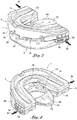
FIG. 2 shows the mandibular advancement device ofFIG. 1 according to a preferred embodiment outside the mouth of the patient and after adjustment; -
FIGs. 3 and 4 show front and rear perspective views of the mandibular advancement device prior to adjustment; -
FIG. 5 shows a front view of the mandibular advancement device; -
FIG. 6 is a cross-section of the mandibular advancement device taken along lines 6-6 ofFIG. 5 ; -
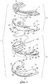
FIGs. 7 and8 show top and bottom exploded views of the mandibular advancement device; and -
FIGs. 9 and10 show top and bottom perspective views of upper and lower tray assemblies prior to their being mated together to complete the mandibular advancement device. - Referring to the drawings, details are now provided of the intra-oral
mandibular advancement appliance 1. according to a preferred embodiment of the present invention. As will be described, themanibular advancement appliance 1 is adapted to fit within the mouth of a patient so that his lower jaw can be advanced forward relative to the upper jaw by a variable distance can be selectively and continuously controlled by the patient. By virtue of the foregoing, theappliance 1 can be manually adjusted by the patient without the use of tools, springs, the removal and insertion of fasteners, or the intervention by medical personnel so that an airway to the throat will remain open whereby to promote adequate breathing while the patient sleeps. It may therefore be appreciated that the intra-oralmandibular advancement appliance 1 has particular application for use by a patient wishing to cope with ' snoring and/or sleep apnea. - Referring initially to
FIGs. 7-10 of the drawings, theappliance 1 includes anupper tray assembly 3 and alower tray assembly 5. As will be described in greater detail hereinafter when referring toFIGs. 3-6 , the upper andlower tray assemblies lower tray assembly 5 can be advanced forwardly by the patient relative toupper tray assembly 3. A forward advancement of thelower tray assembly 5 causes a correspondingly forward displacement of the patient's lower jaw relative to his upper jaw to enable the size of the airway to the patient's throat to be regulated in order to avoid an occlusion and thereby relieve the effects of shoring and/or sleep apnea. - The
upper tray assembly 3 of the intra-oralmandibular advancement appliance 1 includes an upperbite impression tray 7 and an upper chassis 9 to be press fit together so that thetray 7 lies above the chassis 9. Both the upperbite impression tray 7 and upper chassis 9 have a generally arcuate configuration to match the bite pattern of the teeth carried by the upper jaw. The upperbite impression tray 7 is manufactured from a relatively soft and impressionable material such as, for example, that known commercially as EVA manufactured by Dupont The upper chassis 9 is manufactured from a relatively hard and rigid material such as, for example, polycarbonate. - The
lower tray assembly 5 of the intra-oralmandibular advancement appliance 1 includes alower chassis 10 and a lowerbite impression tray 12 to be press fit together so that thechassis 10 lies above thetray 12. Like theupper tray 7 and the upper chassis 9 of theupper tray assembly 3, thelower chassis 10 and the lowerbite impression tray 12 of thelower tray assembly 5 each have a generally arcuate configuration to match the bite pattern of the teeth carried by the lower jaw. Also like theupper tray 7 and the upper chassis 9, thelower chassis 10 is manufactured from a relatively hard and rigid material, while the lowerbite impression tray 12 is manufactured from a relatively soft and impressionable material. - A bite channel 14 (best shown in
FIG. 7 ) runs around the top of the arcuate upperbite impression tray 7 of theupper tray assembly 3. Thebite channel 14 is sized to receive therewithin the set of teeth of the patient carried by his upper jaw bone. Inasmuch as the relatively soft upperbite impression tray 7 lays over and against the relatively hard upper chassis 9, a biting force generated by the patient's upper set of teeth and applied to the upperbite impression tray 7 will shape thebite channel 14 thereof in a manner will soon be described. - A plurality of (e.g., six) locating pins 16 (best shown in
FIG. 8 ) project downwardly from the bottom of the upperbite impression tray 7. In addition, a plurality of (e.g., five) locating tabs 18 (also best shown inFIG. 8 ) project inwardly and outwardly from the arcuate upperbite impression tray 7. The pluralities of locatingpins 16 and locatingtabs 18 enable the upperbite impression tray 7 to be pressed into attachment with the upper chassis 9 to complete theupper tray assembly 3. - A corresponding plurality of locating pin holes 20 extend through the upper chassis 9 of the
upper tray assembly 3. Likewise, a corresponding plurality of locatingtab slots 22 are formed in the upper chassis 9. The locating pin holes 20 and the locatingtab slots 22 of the upper chassis 9 are positioned to receive respective ones of the locating pins 16 and the locatingtabs 18 of the upperbite impression tray 7 so that the upperbite impression tray 7 is seated upon and attached to the upper chassis 9 in response to a squeezing force or pressure applied thereagainst in order to complete theupper tray assembly 3 of themandibular advancement appliance 1. - A pair of guide retention walls 26 (best shown in
FIG. 8 ) are located at the front of the arcuate upper chassis 9. Theguide retention walls 26 run in spaced parallel alignment with one another along the bottom of the upper chassis 9. Aguide path 28 is established in the space between the pair ofguide retention walls 26. As will soon be described, a centering guide (designated 46 inFIG. 7 ) which projects upwardly from thelower chassis 10 of thelower tray assembly 5 is slidably received through theguide path 28 between guide walls 26 r when the upper andlower tray assemblies - Located at each side and formed in the bottom of the upper chassis 9 behind the
guide retention walls 26 is a locking channel 30 (also best shown inFIG. 8 ). The locking channels. 30 run parallel to each other and to theguide path 28 at the front of the upper chassis 9. A row ofteeth 32 is formed (e.g., molded) along one side of each lockingchannel 30. Acatch 34 tuns along and projects from the opposite side of each lockingchannel 30 so as to extend over and above thechannel 30. As will also be described, at the same time that the centeringguide 46 of thelower chassis 10 is slidably received by theguide path 28 of the upper chassis 9, a pair of position adjustment blocks (designated 48 inFIGs. 7 and9 ) which stand upwardly from thelower chassis 10 are pushed through and ride into interlocking engagement with the lockingchannels 30 of the upper chassis 9 to retain the positions of the upper andlower tray assemblies - A bite channel 36 (best shown in
FIG. 8 ) runs around the bottom of the arcuate lowerbite impression tray 12 of thelower tray assembly 5. Thebite channel 36 is sized to receive therewithin the set of teeth of the patient carried by his lower jaw bone. Inasmuch as the relatively soft lowerbite impression tray 12 lays below and against the relatively hardlower chassis 10, a biting force generated by the patient's lower set of teeth and applied to the lowerbite impression tray 12 will shape thebite channel 36 at the same time that thebite channel 14 from the upperbite impression tray 7 is being shaped. - Projecting upwardly from the lower
bite impression tray 12 of thelower tray assembly 5 are a plurality of (e.g., five) locating pins 38 (best shown inFIG. 7 ). A plurality of (e.g., five) locating tabs 40 (also best shown inFIG. 7 ) project inwardly and outwardly from the arcuate lowerbite impression tray 12. The pluralities of locatingpins 38 and locatingtabs 42 enable the lowerbite impression tray 12 to be pressed into attachment with thelower chassis 10 to complete thelower tray assembly 5. - Corresponding pluralities of locating pin holes 42 and locating
tab slots 44 are formed in thelower chassis 10 of thelower tray assembly 5. The locating pin holes 42 and the locatingtab slots 44 of the lower chassis are positioned to receive respective ones ofdie locating pins 38 and the locatingtabs 40 of the lowerbite impression tray 12 so thelower chassis 10 is seated upon and attached to the lowerbite impression tray 12 in response to a squeezing force or pressure applied thereagainst in order to complete thelower tray assembly 5 of themandibular advancement appliance 1. - A centering guide 46 (best shown in
FIG. 7 ) to which reference was made earlier is located at the front of the arcuatelower chassis 10. The centeringguide 46 stands upwardly from the top of thelower chassis 10 between the aforementioned pair of position adjustment blocks 48. One of the locating pin holes 42 of thelower chassis 10 runs through the centeringguide 46 for the receipt therewithin of an opposing one of the locating pins 38 at the front of the lowerbite impression tray 12. As previously described, the centeringguide 46 of thelower chassis 10 is slidably received through theguide path 28 of the upper chassis 9 when theupper tray assembly 3 is mated to thelower tray assembly 5 to complete themandibular advancement appliance 1. - Located at opposite sides of and standing upwardly from the
lower chassis 10 behind the centeringguide 46 is the pair of position adjustment blocks 48 (also best shown inFIG. 7 ). A row ofteeth 50 is formed (e.g., molded) along one side of eachposition adjustment block 48. Alip 52 runs along and projects from the opposite side of each of the position adjustment blocks 48, such that thelips 52 are disposed in spaced opposing alignment. - As was also previously described, at the same time that the centering
guide 46 of thelower chassis 10 is slidably received by theguide path 28 of the upper chassis 9, the pair of position adjustment blocks 48 of thelower chassis 10 are correspondingly aligned to be slidably received by and ride through respective ones of the lockingchannels 30 of the upper chassis 9. Likewise, the opposinglips 52 projecting from the position adjustment blocks 48 slide below and are captured by thecatches 34 which project over and above the locking channels 30 (seeFIG. 5 ), whereby the upper andlower tray assemblies FIGs. 3 and 4 ). In this same regard, theteeth 50 along the pair of position adjustment blocks 48 will move into releasable locking engagement with and mesh against theteeth 32 along the lockingchannels 30. However, any suitable interlocking ratchet means may be substituted for the opposing sets of meshingteeth - As an important feature of this invention, the patient is provided with the ability to release the locking engagement of the
teeth 50 of the position adjustment blocks 48 with theteeth 32 of the lockingchannels 30. By virtue of the foregoing, the position of thelower tray assembly 5 of themandibular advancement device 1 can be selectively changed by a precise distance relative to theupper tray assembly 3 to meet the changing needs of the patient during sleep over time. - More particularly, a pair of position
control push pads 56 are located at and integral to opposite sides of thelower chassis 10 of thelower tray assembly 5. Aposition indicator 58 is molded into or printed outo each of thepush pads 56. The pair of positioncontrol push pads 56 are responsive to compressive squeezing forces (best illustrated inFIGs. 3 and 4 ) applied thereagainst by the patient in order to cause the shape of thelower chassis 10 to be momentarily deformed so that the rows ofteeth lower tray assembly 5 relative to theupper tray assembly 3 to achieve a result will soon be described. - A
position indication scale 60 is located at and integral to each side of the upper chassis 9 of theupper tray assembly 3. A series of position lines are molded into or printed onto each of thescales 60. The increments between each successive pair of position lines of thescales 60 corresponds to a pre-determined linear distance (e.g., one millimeter). In the assembled configuration of the mandibular appliance 1 (best shown inFIGs. 2-5 ) after thelower tray assembly 5 has been moved into sliding mating engagement below theupper tray assembly 3, theposition indication scale 60 at each side of the upper chassis 9 is located directly above the positioncontrol push pad 56 at each side of thelower chassis 10. Theposition indicator 58 of eachpush pad 56 points to a position line which corresponds to a particular distance along eachposition indication scale 60. - Thus, as the position of the
lower tray assembly 5 is slidably adjusted below the upper chassis 9 in the manner shown inFIG. 2 , theposition indicators 58 of theposition control pads 56 will be displaced an identical distance along the position indication scales 60 to provide the patient with a visual indication of the position of thelower tray assembly 5 with respect to theupper tray assembly 3. In this way, the patient can make regular controllable and precise position adjustments to thelower tray assembly 5 for an advantage that will be described when referring hereinafter toFIG. 1 . - The
mandibular advancement appliance 1. also includes a flexibletongue support wire 62 that can be bent and shaped as needed. Thetongue support wire 62 is preferably manufactured from stainless steel, or the like, and is shown with arearward bend 66 to establish a seat upon which a tongue rest 68 (ofFIGs. 3,4 and6 ) is laid. Thetongue rest 68 is pivotally connected to or molded over the top of thewire 62. Thetongue rest 68 is ideally manufactured from a low durometer silicone or urethane and is suspended by thetongue support wire 62 so as to be positioned in the oral cavity and sit on top of the patient's tongue to thereby prevent the tongue from failing back in the mouth and blocking the patient's airway while the patient sleeps on his back with theappliance 1 in his mouth. - The opposite ends 70 of the tongue support wire 62 (best shown in
FIG. 9 ) between which therearward bend 66 is located are detachably connected to and releasably retained by respective ones of the pair of position adjustment blocks 48 at thelower chassis 10 of thelower tray assembly 5. At the same time, the tonguerest support wire 62 is positioned behind and engaged by a pair of wire stops 71 that stand upwardly from thelower chassis 10 to retain thewire 62 in place atop thelower tray assembly 5. When thetongue support wire 62 is detachably connected to the position adjustment blocks 48 and engaged by the wire stops 71, thelower chassis 10 is press fit into attachment with the lowerbite impression tray 12 to complete thelower tray assembly 5 of the mandibular advancement appliance (ofFIGs. 9 and10 ). Therearward bend 66 in thetongue support wire 62 is thusly located within the oral cavity surrounded by the arcuatelower chassis 10 and the lowerbite impression tray 12 at which the tongue rest 68 (ofFIGs. 3 and 4 ) will engage the patient's tongue following the insertion of theappliance 1 into the patient's mouth. Because of comfort considerations during use, the patient may wish to separate thetongue support wire 62 from thelower tray assembly 5. In this case, the ends 70 oftongue support wire 62 are pulled out of their detachable connection with the position adjustment blocks 48 and thewire 62 is disengaged from the wire stops 71 so that thewire 62 and tongue rest 68 are removed together from theappliance 1. -
FIGs. 9 and10 of the drawings show theupper tray assembly 3 positioned over the top of thelower tray assembly 5. The upper andlower tray assemblies mandibular advancement device 1 when, as previously described, the centeringguide 46 which stands upwardly from thelower chassis 10 of thelower tray assembly 5 slides through theguide path 28 between theguide walls 26 of the upper chassis 9 of theupper tray assembly 3 and the position adjustment blocks 48 from thelower chassis 10 of thelower tray assembly 5 are pushed into sliding interlocking engagement with the lockingchannels 30 at the upper chassis 9. -
FIGs. 3-6 of the drawings show the intra-oralmandibular advancement appliance 1 in the assembled ready-to-use configuration after theupper tray assembly 3 and thelower tray assembly 5 have been moved into sliding interlocking engagement with one another in the manner just explained. Thetongue support wire 62 is shown detachably connected to the position adjustment blocks 48 at thelower chassis 10 of thelower tray assembly 5. In this case, thetongue rest 68 which is attached to therearward bend 66 of thetongue support wire 62 is shown suspended fromwire 62 so as to be surrounded by the arcuate upper andlower tray assemblies appliance 1 has been inserted within the patient's mouth. That is, and as was previously described, thetongue rest 68 prevents the patient's tongue from failing (under the influence of gravity) towards his throat during sleep so that the windpipe will not be blocked. - As an option, the
tongue rest 68 is provided with a series of cuttinggrooves 72. A scissors or similar cutting tool may be used to cut thetongue test 68 along one of the cuttinggrooves 72 so that the tongue rest can be shortened by a precise amount depending upon the size of the patient's tongue and comfort considerations. - As is best shown in
FIG. 3 , with theupper tray assembly 3 lying above thelower tray assembly 5, a pair ofair flow passages 76 are established through themandibular advancement appliance 1. In particular, theguide retention walls 26 at the upper chassis 9 of theupper tray assembly 3 between which theguide path 28 is located create gaps between the upper andlower tray assemblies air flow passages 76 throughapparatus 1. Theair flow passages 76 are especially helpful for patients with a deviated septum or a closed nostril to facilitate breathing by ensuring a continuous air flow while the apparatus is used during sleep. - Prior to using the
mandibular advancement appliance 1 for the first time during sleep, the patient boils a pot of water within which the appliance is placed and heated. Theheated appliance 1 is then removed from the boiling water by means of tongs or a similar tool and permitted to cool until it becomes warm. While still warm, theappliance 1 is inserted in the patient's mouth at which time the patient closes his mouth and bites on the relatively soft upperbite impression tray 7 and the lowerbite impression tray 12. The patient's upper set of teeth bites down against thebite channel 14 of the upperbite impression tray 7, and his lower set of teeth bite up against thebite channel 36 of the lowerbite impression tray 12. Impressions of the upper and lower sets of teeth are shaped in the opposing relativelysoft bite channels lower chassis 9 and 10. - At the same time that the patient bites on the upper and lower
bite impression trays FIG. 8 ) and 38 (ofFIG. 7 ) to move completely through their respective oppositely-aligned locking pin holes 20 and 42, whereby the soft upperbite impression tray 7 is affixed to the hard upper chassis 9 to finalize the assembly of theupper tray assembly 3 and the soft lowerbite impression tray 12 is affixed to the hardlower chassis 10 to finalize the assembly of thelower tray assembly 5. Lastly, theappliance 1 is placed into a pot of ice water so that the impression of the patient's upper and lower sets of teeth in thebite channels - The intra-oral
mandibular advancement appliance 1 of this invention is now ready to be used by the patient while he sleeps. Referring in this regard toFIG. 1 of the drawings, theappliance 1 is shown inserted in the mouth of the patient. As previously explained, theappliance 1 is advantageously adapted to position and controllably reposition the patient's lower jaw forward of his upper jaw so that an airway will be continuously opened to the patient's throat so as to minimize the effects of snoring and/or sleep apnea. - More particularly, the patient is provided with the ability to selectively adjust the
mandibular advancement device 1 to prevent the occlusion of his windpipe by causing his lower jaw to be continuously moved forward to meet his changing needs over time.FIG. 2 illustrates the adjustable nature of theappliance 1 after thelower tray assembly 5 thereof is pushed from an initial position lying directly below the upper tray assembly 3 (as shown inFIGs. 3 and 4 ) to the adjusted position ofFIG. 2 where thelower tray assembly 5 is advanced forward of theupper tray assembly 3. inasmuch as the patient's upper and lower sets of teeth are received by thebite channels lower tray assemblies lower tray assembly 5 relative to the upper tray assembly 3 ' will cause a corresponding forward displacement of the patient's lower jaw relative to his upper jaw. - At the same time that the
lower tray assembly 5 moves relative to theupper tray assembly 3, theposition indicator 58 molded into the positioncontrol push pad 56 of thelower tray assembly 5 will move a like distance below to theposition indication scale 60 of theupper tray assembly 3 to provide the patient with a visual indication of the position of his lower jaw. That is to say, as thelower tray assembly 5 is slidably and forwardly advanced, theposition indicator 58 carried thereby will move continuously along theposition indication scale 60 in small (e.g., one millimeter) increments. - To accomplish the selective and continuous forward advancement of the
lower tray assembly 5 of themandibular advancement appliance 1 and the corresponding forward advancement of the patient's lower jaw, the patient applies compressive squeezing forces (designated by thedirectional arrows 80 inFIGs. 3 and 4 ) to the positioncontrol push pads 56 located at opposite sides of thelower chassis 10 of thelower tray assembly 5. The squeezingforces 80 momentarily deform thelower chassis 10 so that theteeth 50 along the position adjustment blocks 48 (ofFIG. 9 ) of thelower chassis 10 are moved out of their meshing locking engagement with opposingteeth 32 along channels 30 (ofFIG. 10 ) of the upper chassis 9. Accordingly, the patient can now pull thelower tray assembly 5 forward by any distance so that the position adjustment blocks 48 ride through respective ones of the lockingchannels 30. - When the forward position of the
lower tray assembly 5 has been adjusted as necessary, the patient releases the squeezing forces applied to positioncontrol push pads 56 so that the original shape of thelower chassis 10 is restored. Themandibular advancement appliance 1 is then inserted in the patient's mouth as shown inFIG. 1 to be used during sleep. Should additional fine adjustments be required over time, such adjustments can be easily and accurately made by the patient at home in the manner described above and without the use of tools, springs, having to remove and return fasteners, or requiring the assistance of medical personnel.
Claims (15)
- An intra-oral mandibular advancement appliance (1) to be inserted in the mouth of a patient so as to permit the position of the lower jaw of the patient to be adjusted relative to the upper jaw to maintain an airway to the throat through which the patient can breathe while sleeping, said appliance comprising:an upper tray assembly (3) having an arcuate shape against which the teeth of the patient's upper jaw are seated, said upper tray assembly having a front and a pair of sides lying opposite and spaced from one another; a lower tray assembly (5) having an arcuate shape against which the teeth of the patient's lower jaw are seated, said lower tray assembly also having a front and a pair of sides lying opposite and spaced from one another; characterized by a position adjustment block (48) located at each of the pair of sides of said lower tray assembly (5); and a locking channel (30) located at each of the pair of sides of said upper tray assembly (3) and, each position adjustment block (48) being slidably received within a respective locking channel, whereby said lower tray assembly (5) is mated in releasable locking engagement to said upper tray assembly (3) to prevent a displacement of said lower tray assembly relative to said upper tray assembly, whereinsaid lower tray assembly (5) is responsive to a lateral compressive squeezing force simultaneously applied to the opposite sides thereof to temporarily change the shape of and deform said lower tray assembly to enable each position adjustment block (48) to slide through its respective locking channel (30) so as to release the locking engagement of said lower tray assembly (5) to said upper tray assembly (3) and thereby permit the positions of said lower tray assembly and the patient's lower jaw to be adjusted relative to the positions of said upper tray assembly and the patient's upper jaw.
- The intra-oral mandibular advancement appliance (1) recited in Claim 1, wherein said lower tray assembly (5) has a push pad (56) located at each of said pair of sides for receipt of said lateral compressive squeezing force thereagainst so that the shape of said arcuate lower tray assembly (5) can be temporarily changed and the position of said lower tray assembly adjusted relative to the position of said upper tray assembly (3).
- The intra-oral mandibular advancement appliance (1) recited in Claim 2, wherein at least one push pad (56) located at one side of said arcuate lower tray assembly (5) has a position indicator (58) and said upper tray assembly (3) has a position indication scale (60), said position indicator moving along said position indication scale when the position of said lower tray assembly is adjusted relative to the position of said upper tray assembly.
- The intra-oral mandibular advancement appliance (1) recited in Claim 1, wherein there is a centering guide (46) located at and standing upwardly from the front of said arcuate lower tray assembly (5) and a guide path (28) located between a pair of guide path walls (26) at the front of said arcuate upper tray assembly (3), said centering guide riding through said guide path between said guide path walls when the position adjustment blocks (48) at the pair of sides of said lower tray assembly slide through the respective locking channels (30) at the pair of sides of said upper tray assembly.
- The intra-oral mandibular advancement appliance (1) recited in Claim 1, wherein the position adjustment blocks (48) and the locking channels (30) located at the pairs of sides of said upper and lower tray assemblies (3, 5) have respective sets of teeth (32, 50) running therealong, the sets of teeth (50) of the position adjustment blocks meshing with the sets of teeth (32) of said locking channels, whereby said lower tray assembly is mated in said releasable locking engagement to said upper tray assembly to prevent a displacement of said lower tray assembly relative to said upper tray assembly.
- The intra-oral mandibular advancement appliance (1) recited in Claim 1, wherein each position adjustment block (48) at each of the pair of sides of said arcuate lower tray assembly (5) has a lip (52) projecting therefrom, the lips projecting from said position adjustment blocks sliding along and being engaged by the pair of sides of said arcuate upper tray assembly (3) when said position adjustment blocks of said arcuate lower tray assembly slide through respective locking channels (30) of said arcuate upper tray assembly.
- The intra-oral mandibular advancement appliance (1) recited in Claim 1, further comprising a tongue rest (68) carried by said appliance and adapted to lay upon the tongue of the patient to prevent the tongue from falling across and blocking the patient's airway.
- The intra-oral mandibular advancement appliance (1) recited in Claim 7, further comprising a tongue rest support (62) to which said tongue rest (68) is connected, said tongue rest support (62) being detachably connected to the position control adjustment blocks (48) located at the pair of sides of said lower tray assembly (5) so that said tongue rest support (62) and said tongue rest (68) connected to said tongue rest support (62) are detachable from said position control adjustment blocks.
- The intra-oral mandibular advancement appliance (1) recited in Claim 1, wherein said upper tray assembly (3) includes a relatively soft and impressionable upper bite portion (7) against which the teeth of the patient's upper jaw are seated and a relatively hard and rigid upper chassis (9) when compared to said upper bite portion, said upper bite portion lying over said upper chassis.
- The intra-oral mandibular advancement appliance (1) recited in Claim 9, wherein the relatively soft and impressionable upper bite portion (7) of said upper tray assembly (3) has a bite channel (14) formed therein within which the teeth of the patient's upper jaw are received, said upper bite portion being responsive to heat applied thereto such that an impression of the teeth of the patient's upper jaw is formed in said bite channel when the patient bites into said upper tray assembly and thereby compresses said relatively soft and impressionable upper bite portion against said relatively hard and rigid upper chassis (9).
- The intra-oral mandibular advancement appliance (1) recited in Claim 10, wherein said lower tray assembly (5) includes a relatively soft and impressionable lower bite portion (12) against which the teeth of the patient's lower jaw are seated and a relatively hard and rigid lower chassis (10) when compared to said lower bite portion, said lower bite portion lying over said lower chassis.
- The intra-oral mandibular advancement appliance (1) recited in Claim 11, wherein the relatively soft and impressionable lower bite portion (12) of said lower tray assembly (5) has a bite channel (36) formed therein within which the teeth of the patient's lower jaw are received, said lower bite portion being responsive to heat applied thereto such that an impression of the teeth of the patient's lower jaw is formed in said bite channel when the patient bites into said lower tray assembly and thereby compresses said relatively soft and impressionable lower bite portion against said relatively hard and rigid lower chassis (10).
- The intra-oral mandibular advancement appliance (1) recited in Claim 1, wherein each of said upper and lower tray assemblies (3, 5) has a relatively soft and impressionable bite portion (7, 12) against which respective sets of the teeth of the patient's upper and lower jaw are seated and a relatively hard and rigid chassis (9, 10) when compared to said bite portion, said bite portion lying over said chassis.
- The intra-oral mandibular advancement appliance (1) recited in Claim 1, wherein there is a centering guide (46) standing upwardly from said lower tray assembly (3) and a guide path (28) formed between a pair of guide path walls (26) located at said upper tray assembly (5), said upstanding centering guide (46) riding through said guide path (28) between said guide path walls (26) at the same time that said position adjustment blocks (48) slide through the respective locking channels (30) and the positions of said lower tray assembly (3) and the patient's lower jaw are adjusted.
- The intra-oral mandibular advancement appliance (1) recited in Claim 1, wherein each upstanding position control block (48) has a lip (52) projecting therefrom and each locking channel (30) has a catch (34) lying thereabove, each lip sliding below and being captured by a respective catch, whereby each position control block is retained within a respective locking channel and said upper and lower tray assemblies (3, 5) are mated together.
Applications Claiming Priority (2)
| Application Number | Priority Date | Filing Date | Title |
|---|---|---|---|
| US13/199,383 US8833374B2 (en) | 2010-12-13 | 2011-08-29 | Intra-oral mandibular advancement appliance |
| PCT/US2012/052207 WO2013032884A1 (en) | 2011-08-29 | 2012-08-24 | Intra-oral mandibular advancement appliance |
Publications (4)
| Publication Number | Publication Date |
|---|---|
| EP2750641A1 EP2750641A1 (en) | 2014-07-09 |
| EP2750641A4 EP2750641A4 (en) | 2015-05-06 |
| EP2750641B1 true EP2750641B1 (en) | 2018-11-14 |
| EP2750641B8 EP2750641B8 (en) | 2019-01-02 |
Family
ID=46198063
Family Applications (1)
| Application Number | Title | Priority Date | Filing Date |
|---|---|---|---|
| EP12827015.4A Active EP2750641B8 (en) | 2011-08-29 | 2012-08-24 | Intra-oral mandibular advancement appliance |
Country Status (10)
| Country | Link |
|---|---|
| US (1) | US8833374B2 (en) |
| EP (1) | EP2750641B8 (en) |
| JP (1) | JP5993457B2 (en) |
| CN (1) | CN103781442B (en) |
| BR (1) | BR112014004653B1 (en) |
| CA (1) | CA2844512C (en) |
| DK (1) | DK2750641T3 (en) |
| ES (1) | ES2705171T3 (en) |
| RU (1) | RU2611764C2 (en) |
| WO (1) | WO2013032884A1 (en) |
Cited By (1)
| Publication number | Priority date | Publication date | Assignee | Title |
|---|---|---|---|---|
| DE102021201915A1 (en) | 2021-03-01 | 2022-09-01 | Jens-Peter Hittel | Device and method for improving sleep breathing and method of making the device |
Families Citing this family (79)
| Publication number | Priority date | Publication date | Assignee | Title |
|---|---|---|---|---|
| US10772756B2 (en) | 2007-11-13 | 2020-09-15 | Somnics, Inc. | Oral device for mandibular advancement and medial tongue constraint |
| US9241825B2 (en) | 2007-11-13 | 2016-01-26 | Apnicure, Inc. | Oral device for mandibular advancement and medial tongue constraint |
| US9655768B2 (en) | 2007-11-13 | 2017-05-23 | Apnicure, Inc. | Oral device for mandibular advancement and medial tongue constraint |
| US8833374B2 (en) * | 2010-12-13 | 2014-09-16 | James S. Fallon | Intra-oral mandibular advancement appliance |
| US20120186589A1 (en) * | 2011-01-26 | 2012-07-26 | Singh Pankaj P | Apparatus and method for treatment of sleep apnea and snoring |
| EP2709572B1 (en) | 2011-05-19 | 2018-07-25 | Oventus Medical Limited | Breathing assist device |
| FR2980684B1 (en) * | 2011-10-04 | 2014-08-22 | Petelle Fleury Rech S Pfr | INTRABUCCAL ORTHESIS, METHOD OF MANUFACTURE, AND METHOD OF USING SUCH ORTHESIS. |
| USD808022S1 (en) | 2012-02-29 | 2018-01-16 | Petruska, Llc | Oral device for preventing snoring and sleep apnea |
| ITRM20120380A1 (en) * | 2012-08-02 | 2014-02-03 | Roberta Ficacci | NEUROPHYSIOLOGICAL STIMULATION DEVICE. |
| EP2695589A1 (en) | 2012-08-10 | 2014-02-12 | Michèle Hervy | Intraoral functional device for relieving obstructive sleep apnea syndrom, snoring and/or other airway disorders |
| EP2961361B1 (en) * | 2013-03-01 | 2021-01-13 | Somnics, Inc. | Oral device for mandibular advancement and medial tongue constraint |
| US9687383B2 (en) | 2013-06-02 | 2017-06-27 | Petruska, Llc | Incremental and/or successive adjustable mandibular advancement device for preventing and treatment of snoring and obstructive sleep apnea |
| DK177809B1 (en) | 2013-06-02 | 2014-07-21 | Natashia Ingemarsson-Matzen | Incremental adjustable mandibular advancement device for |
| US20150101615A1 (en) * | 2013-10-11 | 2015-04-16 | Apnicure, Inc. | Systems, Devices, and Methods for Retaining Oral Devices for Airway Treatment |
| US11576808B2 (en) | 2014-03-19 | 2023-02-14 | Michael Gelb | Apparatus and kit for an oral appliance and method for using same |
| WO2015149127A1 (en) | 2014-04-01 | 2015-10-08 | Oventus Pty Ltd | Breathing assist device |
| EP3156451B1 (en) | 2014-06-10 | 2019-07-24 | Shengyi Technology Co. Ltd. | Halogen-free resin composition, and prepreg and laminated board for printed circuit using same |
| CN107072806B (en) * | 2014-07-02 | 2020-02-11 | 塞拉纳产品股份有限公司 | Sleep apnea oral appliance for use in orthodontic treatment |
| US20210267790A1 (en) * | 2014-07-22 | 2021-09-02 | Arora, Llc | Oral Dental Appliance for Improving Breathing |
| US11033421B1 (en) * | 2014-08-27 | 2021-06-15 | Paul M. Davis | Device to prevent snoring |
| USD760906S1 (en) * | 2015-04-24 | 2016-07-05 | Michael Gelb | Key wedge |
| US10010313B2 (en) | 2015-05-18 | 2018-07-03 | Richard L. Arden | Mandibular subluxation device and method |
| US10258319B2 (en) | 2015-05-18 | 2019-04-16 | Richard L. Arden | Airway assist device and method |
| USD778449S1 (en) | 2015-06-17 | 2017-02-07 | Natashia Ingemarsson-Matzen | Dental plate |
| US10342526B2 (en) | 2015-07-01 | 2019-07-09 | Richard L. Arden | Airway assist device and method |
| GB201602386D0 (en) * | 2015-07-08 | 2016-03-23 | Aria Healthcare Ltd | Improvements to oral devices |
| US20170014262A1 (en) * | 2015-07-14 | 2017-01-19 | Thermal Fit, LLC | Intraoral Orthosis Device and Method for Manufacturing |
| WO2017035531A1 (en) * | 2015-08-27 | 2017-03-02 | Yousefian Joseph | Masticatory and airway stabilizing orthotic, and associated systems and methods |
| FR3041242B1 (en) * | 2015-09-17 | 2017-09-29 | Michel Alglave | INTRABUCCAL DEVICE FOR REPOSITIONING AND REHABILITATION OF LANGUAGE |
| WO2017106896A1 (en) * | 2015-12-22 | 2017-06-29 | Somnomed Limited | A mandibular advancement device |
| KR101832856B1 (en) * | 2016-03-14 | 2018-02-28 | 주식회사 진바이오테크 | Intraoral device for step-snoring and sleep apnea treatment and treating method using the same |
| WO2017165918A1 (en) * | 2016-03-30 | 2017-10-05 | Oventus Medical Limited | Adjustable breathing assistance apparatus |
| CA3029139A1 (en) * | 2016-07-08 | 2018-01-11 | Tongue Lab Europe Ltd. | Dental appliance for sleep apnea, snoring and tongue and oral cavity remodeling |
| US10383761B2 (en) | 2016-08-05 | 2019-08-20 | James S Fallon | Jaw advancement oral appliance to reduce the effects of snoring and/or sleep apnea |
| US11364098B2 (en) * | 2016-09-21 | 2022-06-21 | uLab Systems, Inc. | Combined orthodontic movement of teeth with airway development therapy |
| FR3059544B1 (en) * | 2016-12-07 | 2019-05-10 | Oniris | INTRABUCCAL DEVICE WITH PAIR OF ARTICULATED DENTAL GUTTERS |
| US10905582B2 (en) * | 2017-01-26 | 2021-02-02 | Koncept Innovators Llc | Mandibular advancement device |
| SE543188C2 (en) * | 2017-10-26 | 2020-10-20 | Dormitek Medical Ab | Mouthpiece for reduced snoring, teeth pressing and grinding |
| US12213907B2 (en) | 2017-11-13 | 2025-02-04 | Achaemenid, Llc | Provisional oral sleep appliance |
| US12409060B2 (en) | 2017-11-13 | 2025-09-09 | Achaemenid, Llc | Strut assembly for oral appliance |
| EP3735200B1 (en) * | 2017-11-13 | 2024-01-03 | Achaemenid, LLC | Provisional oral sleep appliance and jig for making the same |
| US10849783B2 (en) * | 2018-01-16 | 2020-12-01 | James S. Fallon | Full movement jaw advancement oral appliance to reduce the effects of snoring and/or sleep apnea |
| EP3746014B1 (en) * | 2018-01-31 | 2023-05-24 | Odin Sleep, LLC | Sleep apnea oral appliance with connectors |
| US11253390B2 (en) | 2018-05-18 | 2022-02-22 | James S Fallon | Impression tray with integral handle for an oral jaw advancement appliance |
| KR102159393B1 (en) * | 2018-07-09 | 2020-09-23 | 장영진 | Snore preventing kit using impression materials of teeth |
| US10251729B1 (en) | 2018-08-31 | 2019-04-09 | 3D Med Ag | Intra-oral device |
| EP3616647A1 (en) | 2018-08-31 | 2020-03-04 | 3D Med Ag | Intra-oral device |
| IT201800009864A1 (en) * | 2018-10-29 | 2020-04-29 | Montefarmaco Otc Spa | DEVICE FOR TEETH AND MOUTH |
| USD888249S1 (en) * | 2019-01-15 | 2020-06-23 | Ryan Bruss | Mouthguard |
| USD932627S1 (en) * | 2019-04-09 | 2021-10-05 | Ji-Young Chung | Mandibular advancement device for anti snoring |
| US12349880B2 (en) * | 2019-07-25 | 2025-07-08 | Paprica Lab. Co., Ltd. | Oral fixation apparatus |
| JP2022547717A (en) * | 2019-09-12 | 2022-11-15 | マイ リトル プロジェクツ シリーズ エイト プランコ トゥエンティファイブ エルエルシー | Tongue Positioner for Sleep Disordered Breathing, Jaw Disorders, and Airway Disorders |
| US11589958B2 (en) | 2019-12-31 | 2023-02-28 | Joseph Yousefian | Pharyngorofacial expander appliance and protocol |
| USD970013S1 (en) * | 2020-01-27 | 2022-11-15 | Frantz Design Incorporated | Mandibular advancement appliance |
| WO2021154930A1 (en) * | 2020-01-28 | 2021-08-05 | Leblanc Dental Products, Inc. | Devices and methods for sleep apnea and snoring |
| USD983374S1 (en) * | 2020-02-10 | 2023-04-11 | JiYoung Chung | Mandibular advancement device for anti snoring |
| WO2021161123A1 (en) * | 2020-02-12 | 2021-08-19 | Americo Fernandes | Multi-function oral appliance |
| WO2021236569A1 (en) * | 2020-05-20 | 2021-11-25 | Arora, Llc | Oral dental appliance for improving breathing |
| US12102555B2 (en) | 2020-08-24 | 2024-10-01 | Sleeping Well Inc. | Oral appliance |
| USD955583S1 (en) | 2020-08-24 | 2022-06-21 | Sleeping Well Llc | Oral appliance |
| AU2020256297A1 (en) * | 2020-10-12 | 2022-04-28 | APAC Health & Medical Distributors PTY LTD | Mandibular advancement device |
| CN112656573A (en) * | 2020-12-09 | 2021-04-16 | 江苏爱朋医疗科技股份有限公司 | Oral cavity correcting snore stopper with tooth-shaped structure adjustment |
| US11166841B1 (en) * | 2021-01-29 | 2021-11-09 | Lubin Martinez | Snoring and sleep apnea prevention device and methods |
| US11311407B1 (en) * | 2021-02-23 | 2022-04-26 | Apnea Sciences Corporation | Bidirectional jaw displacement oral appliance |
| US11793666B1 (en) | 2021-04-16 | 2023-10-24 | Joseph Yousefian | Intra-oral snore and sleep apnea treatment appliance |
| USD995781S1 (en) | 2021-05-28 | 2023-08-15 | Achaemenid, Llc | Strut assembly |
| CN113499185B (en) * | 2021-08-06 | 2023-06-16 | 上海诺斯清生物科技有限公司 | Oral cavity correcting snore stopping device and handle |
| CN114224592B (en) * | 2021-12-09 | 2022-11-04 | 四川大学 | A mandibular advancement snoring device with intelligent automatic adjustment |
| USD1059598S1 (en) | 2021-12-20 | 2025-01-28 | Achaemenid, Llc | Strut assembly |
| US20230277365A1 (en) * | 2022-03-04 | 2023-09-07 | Allen J. Moses | Molar Shim System for Posterior Bite Registration |
| US12097120B2 (en) | 2022-03-07 | 2024-09-24 | Sleep Mechanics Llc | Bone implant device |
| US20240216164A1 (en) | 2022-12-30 | 2024-07-04 | John M Fallon | Multi-directional jaw displacement oral appliance |
| WO2025097229A1 (en) * | 2023-11-06 | 2025-05-15 | Faber Jorge | Device for treating snoring and apnea |
| US20260020973A1 (en) * | 2024-07-18 | 2026-01-22 | Dcstar Inc | Mandibular advancement device with a support baffle |
| US20260020976A1 (en) * | 2024-07-18 | 2026-01-22 | Dcstar Inc | Mandibular advancement device with an adjustment part |
| US20260020975A1 (en) * | 2024-07-18 | 2026-01-22 | Dcstar Inc | Oral appliance |
| CA3267866A1 (en) | 2024-08-06 | 2026-03-01 | Xingchen Liu | Snoring and obstructive sleep apnea prevention device |
| US20260060837A1 (en) * | 2024-08-30 | 2026-03-05 | Yaonan Liang | Anti-snoring mouthpiece |
| JP7850218B1 (en) | 2024-10-15 | 2026-04-22 | 財團法人金屬工業研究發展中心 | Oral cavity positioning member |
Family Cites Families (18)
| Publication number | Priority date | Publication date | Assignee | Title |
|---|---|---|---|---|
| SU1697792A1 (en) * | 1988-11-04 | 1991-12-15 | В.М. Лачинов | Device for reducing stertor |
| US5044950A (en) * | 1989-11-29 | 1991-09-03 | Stanley Hobish | Therapeutic training device and method for fitting dentures |
| US6055986A (en) * | 1992-11-16 | 2000-05-02 | Meade; Thomas E. | Apparatus and method for the reduction of snoring |
| US6041784A (en) | 1993-04-13 | 2000-03-28 | Silent Knights Ventures Inc. | Dental appliance for treatment of snoring and obstructive sleep apnea |
| US5570704A (en) * | 1993-10-28 | 1996-11-05 | Snoreless Corp | Universal, user-adjustable oral cavity appliance to control snoring and reduce episodes of obstructive sleep apnea |
| US5692493A (en) * | 1996-03-08 | 1997-12-02 | Diemolding Corporation | Tongue Protector |
| US5876199A (en) * | 1997-08-28 | 1999-03-02 | Ortho-Tain, Inc. | Appliance adapted to fit many mouth and tooth sizes for orthodontic correction and other uses |
| US5941247A (en) * | 1998-02-17 | 1999-08-24 | Keane; Michael Alexander | Snore prevention apparatus |
| US7832403B2 (en) | 2003-08-07 | 2010-11-16 | Respironics, Inc. | Mandible positioning devices |
| US7748386B2 (en) * | 2006-04-06 | 2010-07-06 | Thornton W Keith | Oral appliance for treating a breathing condition |
| EP2032067B1 (en) * | 2006-06-14 | 2015-09-30 | RIC Investments, LLC. | Oral appliance for treatment of snoring and sleep apnea |
| AU2007202799A1 (en) * | 2007-06-15 | 2009-01-08 | John Razmovski | Improved Oral Cavity Manipulator |
| US8127769B2 (en) | 2007-11-18 | 2012-03-06 | Dreamscape Medical Llc | Integrated oral appliance for sleep-disordered breathing |
| US20100261133A1 (en) | 2009-04-08 | 2010-10-14 | Lax Ronald G | Devices, systems, and methods for repositioning the mandible |
| US20110099846A1 (en) | 2009-06-16 | 2011-05-05 | Bruce Fischer | Alpine ski boot with strap closure |
| US8631800B2 (en) * | 2009-06-29 | 2014-01-21 | Sleep Science Partners, Inc. | Self-titratable mandibular repositioning device |
| US8256426B2 (en) * | 2009-08-12 | 2012-09-04 | Abramson Mark E | Modular dental appliance for improving airflow through nasal-pharyngeal airway |
| US8833374B2 (en) * | 2010-12-13 | 2014-09-16 | James S. Fallon | Intra-oral mandibular advancement appliance |
-
2011
- 2011-08-29 US US13/199,383 patent/US8833374B2/en active Active
-
2012
- 2012-08-24 DK DK12827015.4T patent/DK2750641T3/en active
- 2012-08-24 RU RU2014105692A patent/RU2611764C2/en active
- 2012-08-24 CA CA2844512A patent/CA2844512C/en active Active
- 2012-08-24 CN CN201280042382.3A patent/CN103781442B/en active Active
- 2012-08-24 JP JP2014528471A patent/JP5993457B2/en active Active
- 2012-08-24 ES ES12827015T patent/ES2705171T3/en active Active
- 2012-08-24 WO PCT/US2012/052207 patent/WO2013032884A1/en not_active Ceased
- 2012-08-24 BR BR112014004653-0A patent/BR112014004653B1/en active IP Right Grant
- 2012-08-24 EP EP12827015.4A patent/EP2750641B8/en active Active
Non-Patent Citations (1)
| Title |
|---|
| None * |
Cited By (1)
| Publication number | Priority date | Publication date | Assignee | Title |
|---|---|---|---|---|
| DE102021201915A1 (en) | 2021-03-01 | 2022-09-01 | Jens-Peter Hittel | Device and method for improving sleep breathing and method of making the device |
Also Published As
| Publication number | Publication date |
|---|---|
| CN103781442B (en) | 2016-10-19 |
| RU2014105692A (en) | 2015-10-27 |
| HK1198510A1 (en) | 2015-05-15 |
| BR112014004653B1 (en) | 2022-03-22 |
| JP5993457B2 (en) | 2016-09-14 |
| BR112014004653A2 (en) | 2017-06-13 |
| DK2750641T3 (en) | 2019-01-28 |
| CN103781442A (en) | 2014-05-07 |
| ES2705171T3 (en) | 2019-03-22 |
| WO2013032884A1 (en) | 2013-03-07 |
| US8833374B2 (en) | 2014-09-16 |
| EP2750641A1 (en) | 2014-07-09 |
| EP2750641B8 (en) | 2019-01-02 |
| CA2844512C (en) | 2018-12-11 |
| CA2844512A1 (en) | 2013-03-07 |
| EP2750641A4 (en) | 2015-05-06 |
| JP2014525321A (en) | 2014-09-29 |
| RU2611764C2 (en) | 2017-02-28 |
| US20120145166A1 (en) | 2012-06-14 |
Similar Documents
| Publication | Publication Date | Title |
|---|---|---|
| US8833374B2 (en) | Intra-oral mandibular advancement appliance | |
| US10383761B2 (en) | Jaw advancement oral appliance to reduce the effects of snoring and/or sleep apnea | |
| US8205617B2 (en) | Oral appliance for treatment of snoring and sleep apnea | |
| US10849783B2 (en) | Full movement jaw advancement oral appliance to reduce the effects of snoring and/or sleep apnea | |
| US11357662B2 (en) | Mandible adjustment apparatus | |
| US11723792B2 (en) | Oral appliance device | |
| EP4046607B1 (en) | Bidirectional jaw displacement oral appliance | |
| HK1198510B (en) | Intra-oral mandibular advancement appliance | |
| US20180338856A1 (en) | Systems, methods and oral appliance devices | |
| EP4393456A1 (en) | Multi-directional jaw displacement oral appliance | |
| KR102830977B1 (en) | Mandibular displacement control device | |
| HK40073128A (en) | Bidirectional jaw displacement oral appliance |
Legal Events
| Date | Code | Title | Description |
|---|---|---|---|
| PUAI | Public reference made under article 153(3) epc to a published international application that has entered the european phase |
Free format text: ORIGINAL CODE: 0009012 |
|
| 17P | Request for examination filed |
Effective date: 20140228 |
|
| AK | Designated contracting states |
Kind code of ref document: A1 Designated state(s): AL AT BE BG CH CY CZ DE DK EE ES FI FR GB GR HR HU IE IS IT LI LT LU LV MC MK MT NL NO PL PT RO RS SE SI SK SM TR |
|
| DAX | Request for extension of the european patent (deleted) | ||
| RA4 | Supplementary search report drawn up and despatched (corrected) |
Effective date: 20150402 |
|
| RIC1 | Information provided on ipc code assigned before grant |
Ipc: A61F 5/56 20060101AFI20150327BHEP |
|
| 17Q | First examination report despatched |
Effective date: 20160926 |
|
| STAA | Information on the status of an ep patent application or granted ep patent |
Free format text: STATUS: EXAMINATION IS IN PROGRESS |
|
| GRAP | Despatch of communication of intention to grant a patent |
Free format text: ORIGINAL CODE: EPIDOSNIGR1 |
|
| STAA | Information on the status of an ep patent application or granted ep patent |
Free format text: STATUS: GRANT OF PATENT IS INTENDED |
|
| INTG | Intention to grant announced |
Effective date: 20180608 |
|
| GRAS | Grant fee paid |
Free format text: ORIGINAL CODE: EPIDOSNIGR3 |
|
| GRAA | (expected) grant |
Free format text: ORIGINAL CODE: 0009210 |
|
| STAA | Information on the status of an ep patent application or granted ep patent |
Free format text: STATUS: THE PATENT HAS BEEN GRANTED |
|
| AK | Designated contracting states |
Kind code of ref document: B1 Designated state(s): AL AT BE BG CH CY CZ DE DK EE ES FI FR GB GR HR HU IE IS IT LI LT LU LV MC MK MT NL NO PL PT RO RS SE SI SK SM TR |
|
| REG | Reference to a national code |
Ref country code: CH Ref legal event code: EP Ref country code: AT Ref legal event code: REF Ref document number: 1063925 Country of ref document: AT Kind code of ref document: T Effective date: 20181115 |
|
| REG | Reference to a national code |
Ref country code: DE Ref legal event code: R082 Ref document number: 602012053585 Country of ref document: DE Representative=s name: WAGNER & GEYER PARTNERSCHAFT MBB PATENT- UND R, DE Ref country code: DE Ref legal event code: R081 Ref document number: 602012053585 Country of ref document: DE Owner name: APNEA SCIENCES CORP., ALISO VIEJO, US Free format text: FORMER OWNER: APNEA SCIENCES CORP., LAGUNA NIGUEL, CA, US |
|
| REG | Reference to a national code |
Ref country code: DE Ref legal event code: R096 Ref document number: 602012053585 Country of ref document: DE |
|
| REG | Reference to a national code |
Ref country code: IE Ref legal event code: FG4D |
|
| REG | Reference to a national code |
Ref country code: CH Ref legal event code: PK Free format text: BERICHTIGUNG B8 |
|
| REG | Reference to a national code |
Ref country code: DK Ref legal event code: T3 Effective date: 20190123 |
|
| REG | Reference to a national code |
Ref country code: SE Ref legal event code: TRGR |
|
| REG | Reference to a national code |
Ref country code: NL Ref legal event code: MP Effective date: 20181114 |
|
| REG | Reference to a national code |
Ref country code: ES Ref legal event code: FG2A Ref document number: 2705171 Country of ref document: ES Kind code of ref document: T3 Effective date: 20190322 |
|
| REG | Reference to a national code |
Ref country code: LT Ref legal event code: MG4D |
|
| REG | Reference to a national code |
Ref country code: GR Ref legal event code: EP Ref document number: 20180403888 Country of ref document: GR Effective date: 20190422 |
|
| PG25 | Lapsed in a contracting state [announced via postgrant information from national office to epo] |
Ref country code: LT Free format text: LAPSE BECAUSE OF FAILURE TO SUBMIT A TRANSLATION OF THE DESCRIPTION OR TO PAY THE FEE WITHIN THE PRESCRIBED TIME-LIMIT Effective date: 20181114 Ref country code: HR Free format text: LAPSE BECAUSE OF FAILURE TO SUBMIT A TRANSLATION OF THE DESCRIPTION OR TO PAY THE FEE WITHIN THE PRESCRIBED TIME-LIMIT Effective date: 20181114 Ref country code: LV Free format text: LAPSE BECAUSE OF FAILURE TO SUBMIT A TRANSLATION OF THE DESCRIPTION OR TO PAY THE FEE WITHIN THE PRESCRIBED TIME-LIMIT Effective date: 20181114 Ref country code: NO Free format text: LAPSE BECAUSE OF FAILURE TO SUBMIT A TRANSLATION OF THE DESCRIPTION OR TO PAY THE FEE WITHIN THE PRESCRIBED TIME-LIMIT Effective date: 20190214 Ref country code: IS Free format text: LAPSE BECAUSE OF FAILURE TO SUBMIT A TRANSLATION OF THE DESCRIPTION OR TO PAY THE FEE WITHIN THE PRESCRIBED TIME-LIMIT Effective date: 20190314 |
|
| PG25 | Lapsed in a contracting state [announced via postgrant information from national office to epo] |
Ref country code: NL Free format text: LAPSE BECAUSE OF FAILURE TO SUBMIT A TRANSLATION OF THE DESCRIPTION OR TO PAY THE FEE WITHIN THE PRESCRIBED TIME-LIMIT Effective date: 20181114 Ref country code: AL Free format text: LAPSE BECAUSE OF FAILURE TO SUBMIT A TRANSLATION OF THE DESCRIPTION OR TO PAY THE FEE WITHIN THE PRESCRIBED TIME-LIMIT Effective date: 20181114 Ref country code: PT Free format text: LAPSE BECAUSE OF FAILURE TO SUBMIT A TRANSLATION OF THE DESCRIPTION OR TO PAY THE FEE WITHIN THE PRESCRIBED TIME-LIMIT Effective date: 20190314 Ref country code: RS Free format text: LAPSE BECAUSE OF FAILURE TO SUBMIT A TRANSLATION OF THE DESCRIPTION OR TO PAY THE FEE WITHIN THE PRESCRIBED TIME-LIMIT Effective date: 20181114 |
|
| PG25 | Lapsed in a contracting state [announced via postgrant information from national office to epo] |
Ref country code: PL Free format text: LAPSE BECAUSE OF FAILURE TO SUBMIT A TRANSLATION OF THE DESCRIPTION OR TO PAY THE FEE WITHIN THE PRESCRIBED TIME-LIMIT Effective date: 20181114 Ref country code: IT Free format text: LAPSE BECAUSE OF FAILURE TO SUBMIT A TRANSLATION OF THE DESCRIPTION OR TO PAY THE FEE WITHIN THE PRESCRIBED TIME-LIMIT Effective date: 20181114 |
|
| REG | Reference to a national code |
Ref country code: DE Ref legal event code: R097 Ref document number: 602012053585 Country of ref document: DE |
|
| PG25 | Lapsed in a contracting state [announced via postgrant information from national office to epo] |
Ref country code: SM Free format text: LAPSE BECAUSE OF FAILURE TO SUBMIT A TRANSLATION OF THE DESCRIPTION OR TO PAY THE FEE WITHIN THE PRESCRIBED TIME-LIMIT Effective date: 20181114 Ref country code: SK Free format text: LAPSE BECAUSE OF FAILURE TO SUBMIT A TRANSLATION OF THE DESCRIPTION OR TO PAY THE FEE WITHIN THE PRESCRIBED TIME-LIMIT Effective date: 20181114 Ref country code: RO Free format text: LAPSE BECAUSE OF FAILURE TO SUBMIT A TRANSLATION OF THE DESCRIPTION OR TO PAY THE FEE WITHIN THE PRESCRIBED TIME-LIMIT Effective date: 20181114 Ref country code: EE Free format text: LAPSE BECAUSE OF FAILURE TO SUBMIT A TRANSLATION OF THE DESCRIPTION OR TO PAY THE FEE WITHIN THE PRESCRIBED TIME-LIMIT Effective date: 20181114 |
|
| PLBE | No opposition filed within time limit |
Free format text: ORIGINAL CODE: 0009261 |
|
| STAA | Information on the status of an ep patent application or granted ep patent |
Free format text: STATUS: NO OPPOSITION FILED WITHIN TIME LIMIT |
|
| 26N | No opposition filed |
Effective date: 20190815 |
|
| PG25 | Lapsed in a contracting state [announced via postgrant information from national office to epo] |
Ref country code: SI Free format text: LAPSE BECAUSE OF FAILURE TO SUBMIT A TRANSLATION OF THE DESCRIPTION OR TO PAY THE FEE WITHIN THE PRESCRIBED TIME-LIMIT Effective date: 20181114 |
|
| PG25 | Lapsed in a contracting state [announced via postgrant information from national office to epo] |
Ref country code: TR Free format text: LAPSE BECAUSE OF FAILURE TO SUBMIT A TRANSLATION OF THE DESCRIPTION OR TO PAY THE FEE WITHIN THE PRESCRIBED TIME-LIMIT Effective date: 20181114 |
|
| PG25 | Lapsed in a contracting state [announced via postgrant information from national office to epo] |
Ref country code: LI Free format text: LAPSE BECAUSE OF NON-PAYMENT OF DUE FEES Effective date: 20190831 Ref country code: LU Free format text: LAPSE BECAUSE OF NON-PAYMENT OF DUE FEES Effective date: 20190824 Ref country code: CH Free format text: LAPSE BECAUSE OF NON-PAYMENT OF DUE FEES Effective date: 20190831 Ref country code: MC Free format text: LAPSE BECAUSE OF FAILURE TO SUBMIT A TRANSLATION OF THE DESCRIPTION OR TO PAY THE FEE WITHIN THE PRESCRIBED TIME-LIMIT Effective date: 20181114 |
|
| PG25 | Lapsed in a contracting state [announced via postgrant information from national office to epo] |
Ref country code: IE Free format text: LAPSE BECAUSE OF NON-PAYMENT OF DUE FEES Effective date: 20190824 |
|
| PG25 | Lapsed in a contracting state [announced via postgrant information from national office to epo] |
Ref country code: CY Free format text: LAPSE BECAUSE OF FAILURE TO SUBMIT A TRANSLATION OF THE DESCRIPTION OR TO PAY THE FEE WITHIN THE PRESCRIBED TIME-LIMIT Effective date: 20181114 |
|
| PG25 | Lapsed in a contracting state [announced via postgrant information from national office to epo] |
Ref country code: MT Free format text: LAPSE BECAUSE OF FAILURE TO SUBMIT A TRANSLATION OF THE DESCRIPTION OR TO PAY THE FEE WITHIN THE PRESCRIBED TIME-LIMIT Effective date: 20181114 Ref country code: HU Free format text: LAPSE BECAUSE OF FAILURE TO SUBMIT A TRANSLATION OF THE DESCRIPTION OR TO PAY THE FEE WITHIN THE PRESCRIBED TIME-LIMIT; INVALID AB INITIO Effective date: 20120824 |
|
| PG25 | Lapsed in a contracting state [announced via postgrant information from national office to epo] |
Ref country code: MK Free format text: LAPSE BECAUSE OF FAILURE TO SUBMIT A TRANSLATION OF THE DESCRIPTION OR TO PAY THE FEE WITHIN THE PRESCRIBED TIME-LIMIT Effective date: 20181114 |
|
| PGFP | Annual fee paid to national office [announced via postgrant information from national office to epo] |
Ref country code: FI Payment date: 20250814 Year of fee payment: 14 Ref country code: ES Payment date: 20250902 Year of fee payment: 14 |
|
| PGFP | Annual fee paid to national office [announced via postgrant information from national office to epo] |
Ref country code: DK Payment date: 20250814 Year of fee payment: 14 Ref country code: DE Payment date: 20250827 Year of fee payment: 14 |
|
| PGFP | Annual fee paid to national office [announced via postgrant information from national office to epo] |
Ref country code: GR Payment date: 20250725 Year of fee payment: 14 |
|
| PGFP | Annual fee paid to national office [announced via postgrant information from national office to epo] |
Ref country code: BG Payment date: 20250729 Year of fee payment: 14 Ref country code: BE Payment date: 20250818 Year of fee payment: 14 Ref country code: GB Payment date: 20250826 Year of fee payment: 14 |
|
| PGFP | Annual fee paid to national office [announced via postgrant information from national office to epo] |
Ref country code: FR Payment date: 20250827 Year of fee payment: 14 Ref country code: AT Payment date: 20250725 Year of fee payment: 14 |
|
| PGFP | Annual fee paid to national office [announced via postgrant information from national office to epo] |
Ref country code: SE Payment date: 20250728 Year of fee payment: 14 |
|
| PGFP | Annual fee paid to national office [announced via postgrant information from national office to epo] |
Ref country code: CZ Payment date: 20250730 Year of fee payment: 14 |