EP2750281A1 - Piezoelectric power generation element - Google Patents
Piezoelectric power generation element Download PDFInfo
- Publication number
- EP2750281A1 EP2750281A1 EP12847297.4A EP12847297A EP2750281A1 EP 2750281 A1 EP2750281 A1 EP 2750281A1 EP 12847297 A EP12847297 A EP 12847297A EP 2750281 A1 EP2750281 A1 EP 2750281A1
- Authority
- EP
- European Patent Office
- Prior art keywords
- generating device
- power generating
- lever
- piezoelectric power
- piezoelectric
- Prior art date
- Legal status (The legal status is an assumption and is not a legal conclusion. Google has not performed a legal analysis and makes no representation as to the accuracy of the status listed.)
- Granted
Links
Images



Classifications
-
- H—ELECTRICITY
- H02—GENERATION; CONVERSION OR DISTRIBUTION OF ELECTRIC POWER
- H02N—ELECTRIC MACHINES NOT OTHERWISE PROVIDED FOR
- H02N2/00—Electric machines in general using piezoelectric effect, electrostriction or magnetostriction
- H02N2/18—Electric machines in general using piezoelectric effect, electrostriction or magnetostriction producing electrical output from mechanical input, e.g. generators
Definitions
- the present invention relates to a piezoelectric power generating device that includes a piezoelectric element.
- a piezoelectric power generating device that includes a piezoelectric element is known as a small-sized power generating device (see, for example, Patent Document 1). Since a piezoelectric power generating device includes a piezoelectric element and a member that applies a stress to the piezoelectric element when an external force such as vibration is applied to the member, the configuration of such a piezoelectric power generating device can be simplified, and such a piezoelectric power generating device can be reduced in size. Therefore, a piezoelectric power generating device is expected to have a wide range of applications such as, for example, in a power supply of a wireless device for a tire pressure monitoring system (TPMS) that is mounted in the interior of a tire.
- TPMS tire pressure monitoring system
- Patent Document 1 Japanese Unexamined Patent Application Publication No. 2008-54450
- a first piezoelectric power generating device includes a piezoelectric element, a stopper, and a lever.
- the piezoelectric element has a first surface and a second surface. The first surface is positioned on one side in a first direction. The second surface is positioned on the other side in the first direction. The second surface opposes the first surface.
- the stopper has a first contact surface. The first contact surface is in contact with the first surface.
- the lever includes a contact portion and a displacement portion. The contact portion includes a second contact surface. The second contact surface is in contact with the second surface. The displacement portion is positioned further toward the one side in the first direction than the second surface.
- the lever is arranged in such a manner as to be rotatable relative to the stopper around a rotation axis extending in a second direction that is perpendicular to the first direction.
- the lever is arranged in such a manner that the second contact surface presses the second surface when the displacement portion rotates relative to the stopper around the rotation axis.
- the lever is rotatably supported by the stopper.
- a shortest distance between the contact portion and the rotation axis is smaller than a shortest distance between the displacement portion and the rotation axis.
- the piezoelectric power generating device further includes an urging member.
- the urging member urges, when the lever rotates relative to the stopper in a direction, the lever in a direction opposite to the direction in which the lever rotates.
- the urging member urges the displacement portion.
- the piezoelectric power generating device further includes a drive mechanism that causes the lever to rotate several times around the rotation axis.
- a second piezoelectric power generating device includes a piezoelectric body and a stress applying member.
- the stress applying member applies a stress to the piezoelectric body.
- the second piezoelectric power generating device further includes a drive mechanism.
- the drive mechanism drives the stress applying member in such a manner that the stress applying member applies a stress several times to the piezoelectric body when an external force is applied to the piezoelectric power generating device.
- a small-sized piezoelectric power generating device can be provided.
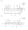
- Fig. 1 is a schematic perspective view of a piezoelectric power generating device 1 according to a first embodiment of the present invention.
- Fig. 2 is a schematic plan view of the piezoelectric power generating device 1 according to the first embodiment of the present invention.
- Fig. 3 is a schematic side view of the piezoelectric power generating device 1 according to the first embodiment of the present invention.
- Fig. 4 is a schematic front view of the piezoelectric power generating device 1 according to the first embodiment of the present invention.
- x-y-z axes of a rectangular coordinate system that are formed of an x axis, a y axis, which is perpendicular to the x axis, and a z axis, which is perpendicular to the x axis and the y axis, are illustrated.
- the x-axis direction, the y-axis direction, and the z-axis direction are a first direction, a second direction, and a third direction, respectively.
- the piezoelectric power generating device 1 includes a piezoelectric element 10, a stopper 20, and a lever 30.
- the piezoelectric element 10 includes a piezoelectric body and an electrode.
- the piezoelectric body can be made of, for example, lead zirconate titanate (PZT) or the like.
- the electrode may be arranged in any manner as long as the electrode can extract power that is generated in the piezoelectric body.
- a pair of the electrodes may be arranged in such a manner that the piezoelectric body is clamped therebetween.
- Each electrode of the pair of electrodes may be formed of a plurality of electrodes.
- the piezoelectric element 10 is in the form of a column. More specifically, the piezoelectric element 10 is in the form of a square column.
- the piezoelectric element 10 has a first surface 10a and a second surface 10b. The first surface 10a and the second surface 10b oppose each other in the x-axis direction.
- the first surface 10a is positioned on the x1 side in the x-axis direction.
- the second surface 10b is positioned on the x2 side in the x-axis direction.
- the piezoelectric element 10 may be formed of a multilayer piezoelectric body that includes a plurality of piezoelectric layers and a plurality of inner electrodes stacked on top of one another.
- the piezoelectric element 10 need not be in a columnar shape and may be in a different shape such as a flat plate-like shape as long as the piezoelectric element 10 has two surfaces that oppose each other.
- the stopper 20 includes a contact portion 21, a support portion 22, a connecting portion 23, and a shaft 24.
- the contact portion 21 is positioned further toward the x1 side in the x-axis direction than the first surface 10a.
- the contact portion 21 has a first contact surface 21a.
- the first contact surface 21a and the first surface 10a face each other and are in contact with each other.
- the support portion 22 is positioned further toward the x2 side in the x-axis direction than the second surface 10b.
- the support portion 22 and the contact portion 21 are connected by the connecting portion 23.
- the connecting portion 23 is positioned further toward the z2 side in the z-axis direction than the piezoelectric element 10.
- the support portion 22 is provided with the shaft 24 that extends along the y-axis direction.
- the lever 30 is supported by the shaft 24 in such a manner as to be rotatable around the shaft 24. Therefore, the lever 30 is rotatable relative to the stopper 20 around a rotation axis that extends in the y-axis direction, which is the second direction and is perpendicular to the x-axis direction, which is the first direction.
- the lever 30 includes a contact portion 31, a displacement portion 32, and a connecting portion 33.
- the contact portion 31 is positioned further toward the x2 side in the x-axis direction than the second surface 10b.
- the contact portion 31 is disposed in an area inside the stopper 20 in the y-axis direction.
- the contact portion 31 has a second contact surface 31a.
- the second contact surface 31a and the second surface 10b face each other and are in contact with each other.
- the displacement portion 32 is positioned further toward the x1 side in the x-axis direction than the second surface 10b. More specifically, in the present embodiment, the displacement portion 32 is positioned further toward the x1 side in the x-axis direction than the first surface 10a.
- the displacement portion 32 is disposed in an area inside the stopper 20 in the y-axis direction. An end portion of the displacement portion 32 on the z1 side in the z-axis direction is positioned further toward the z1 side than an end portion of the contact portion 21 on the z1 side in the z-axis direction. Therefore, a force toward the z2 side in the z-axis direction can be easily applied to the displacement portion 32.
- the displacement portion 32 and the contact portion 31 are connected by the connecting portion 33.
- the connecting portion 33 is positioned further toward the z2 side in the z-axis direction than the piezoelectric element 10.
- the piezoelectric power generating device 1 when an operator operates the lever 30 or when vibration, an external force, or the like is applied to the piezoelectric power generating device 1, a force toward the z2 side in the z-axis direction is applied to the displacement portion 32 of the lever 30, and the lever 30 rotates relative to the stopper 20 around the rotation axis (the central axis of the shaft 24), so that, upon the rotation, the second contact surface 31a of the contact portion 31 also rotates around the rotation axis. Therefore, the second contact surface 31a of the contact portion 31 presses the second surface 10b of the piezoelectric element 10 toward the x1 side in the x-axis direction.
- the second contact surface 31a presses the second surface 10b toward the x1 side in the x-axis direction and the z2 side in the z-axis direction. Therefore, a stress is applied to the piezoelectric element 10. As a result, power is generated in the piezoelectric element 10 by the piezoelectric effect.
- the piezoelectric power generating device 1 is provided with an urging member 40 (see Fig. 3 ).
- the urging member 40 urges the lever 30, specifically, the displacement portion 32 of the lever 30 in a direction opposite to the rotation direction of the lever 30. Therefore, the urging member 40 helps the lever 30, which has rotated, return to the original position.
- the urging member 40 is formed of, for example, a spring or the like.
- the displacement portion 32 of the lever 30 is positioned further toward the x1 side in the x-axis direction (the side of the first surface 10a) than the second surface 10b.
- the connecting portion 33 of the lever 30 is positioned further toward the z2 side in the z-axis direction than the piezoelectric element 10.
- the shaft 24 is disposed in such a manner that the shortest distance between the contact portion 31 and the rotation axis is smaller than the shortest distance between the displacement portion 32 and the rotation axis.
- a pressing force of the second contact surface 31a toward the piezoelectric element 10 is increased by the principle of leverage. Therefore, a further reduction in the size of the piezoelectric power generating device 1 and high power generation efficiency can be facilitated.
- the lever 30 is rotatably supported by the stopper 20.
- the stopper 20 it is not necessary to provide a member that supports the lever 30 separately from the stopper 20. Therefore, a further reduction in the size of the piezoelectric power generating device 1 can be facilitated.
- the piezoelectric power generating device 1 is provided with the urging member 40, when a stress toward the z2 side in the z-axis direction is applied to the displacement portion 32 of the lever 30, the lever 30 may swing several times. In addition, the time taken for the lever 30 to return to the original position is reduced by the urging member 40. Therefore, an increase in the power generation amount of the piezoelectric power generating device 1 can be facilitated.
- the urging member 40 is arranged in such a manner as to urge the displacement portion 32, which is positioned so as to be spaced apart from the rotation axis, and thus, the time taken for the lever 30 to return to the original position is further reduced. Therefore, a further increase in the power generation amount of the piezoelectric power generating device 1 can be facilitated.
- Fig. 5 is a schematic perspective view of a piezoelectric power generating device 2 according to a second embodiment of the present invention.
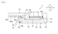
- Fig. 6 is a schematic side view of the piezoelectric power generating device 2 according to the second embodiment of the present invention.
- the piezoelectric power generating device 2 according to the second embodiment of the present invention includes a slide member 50 that functions as a drive mechanism.
- the slide member 50 When a stress along the x-axis direction, which is the first direction, is applied to the piezoelectric power generating device 2, the slide member 50 causes the lever 30 to rotate around the rotation axis.
- the slide member 50 is arranged in such a manner as to be displaceable with respect to the stopper 20 and the lever 30 in the x-axis direction, which is the first direction.
- the slide member 50 is positioned further toward the z1 side in the z-axis direction than the stopper 20 and the lever 30.
- the slide member 50 includes a plurality of protruding portions 50a that protrude toward the z2 side in the z-axis direction.
- the plurality of protruding portions 50a are arranged in such a manner as to be superposed with a bar-shaped member 32a that is provided to the displacement portion 32 in the x-axis direction.
- the bar-shaped member 32a is disposed in such a manner as to extend along the y-axis direction.
- the plurality of protruding portions 50a each have a pair of inclined surfaces 50a1 and 50a2 that are inclined to the x-axis direction.
- the inclination angle of the inclined surface 50a1 with respect to the x-axis direction (the displacement direction of the slide member 50) and the inclination angle of the inclined surface 50a2 with respect to the x-axis direction may be the same as each other or different from each other.
- the inclination angle of the inclined surface 50a2 with respect to the x-axis direction may be greater than the inclination angle of the inclined angle 50a1 with respect to the x-axis direction.
- the inclined surfaces 50a1 and 50a2 are planar in the present embodiment, the inclined surfaces 50a1 and 50a2 may be curved.
- the cross-sectional shape of the outline of the slide member 50, which includes the plurality of protruding portions 50a may include a wave-shaped portion at least a part of which is formed of a curved line such as a sine curve.
- the piezoelectric power generating device 2 includes the slide member 50 that functions as a drive mechanism and that drives the lever 30, which functions as a stress applying member, in such a manner that the lever 30 applies a stress several times to the piezoelectric element 10 when an external force is applied once to the piezoelectric power generating device 2.
- the slide member 50 is displaced relative to the stopper 20 and the lever 30 in the x-axis direction.
- the bar-shaped member 32a is pressed toward the z2 side by the at least one of the plurality of protruding portions 50a.
- the number of the plurality of protruding portions 50a that pass across the bar-shaped member 32a in the x-axis direction may be one or more depending on the amount of displacement of the slide member 50 in the x-axis direction, and the bar-shaped member 32a is pressed several times toward the z2 side by the plurality of protruding portions 50a.
- the piezoelectric power generating device 2 even if the magnitude of a stress that is applied to the piezoelectric element 10 as a result of a single rotation of the lever 30 is small, the lever 30 is rotated several times by the slide member 50, so that a stress is applied several times to the piezoelectric element 10, and as a result, a large power generation amount can be obtained on the whole. Therefore, a large power generation amount can be obtained without applying a large stress to the piezoelectric element 10 at the same time.
- an elastic member 51 that is formed of a spring or the like is connected to the slide member 50, and thus, the number of times the slide member 50 is displaced in the x-axis direction when a stress is applied to the slide member 50 increases. Therefore, an improved power generation efficiency and further large power generation amount can be realized.
- power is generated in the piezoelectric power generating device 2 not only when vibration or an external force along the z-axis direction is applied to the piezoelectric power generating device 2 but also when vibration or an external force along the x-axis direction is applied to the piezoelectric power generating device 2.
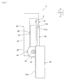
- Fig. 7 is a schematic side view of a piezoelectric power generating device 3 according to a third embodiment of the present invention.
- Fig. 8 is a schematic perspective view of the piezoelectric power generating device 3 according to the third embodiment of the present invention.
- Fig. 9 is a schematic exploded perspective view of the piezoelectric power generating device 3 according to the third embodiment of the present invention.
- the lever 30 is directly connected to the stopper 20.
- the stopper 20 and the lever 30 are integrally formed.
- the displacement portion 32 is provided with a shaft 63.
- a cam 61 is rotatably mounted on the stopper 20.
- the cam 61 has a non-circular shape when seen in plan view. More specifically, the cam 61 has an approximately polygonal shape, and more particularly, an approximately rectangular shape when seen in plan view.
- the outer peripheral surface of the cam 61 and the outer peripheral surface of the shaft 63 are in contact with each other.
- a shaft 62 is non-rotatably fixed to a center portion of the cam 61.
- a gear is disposed on the outer peripheral surface of the shaft 62.
- the slide member 50 which functions as a drive mechanism, is positioned on one side of the shaft 62 in the z-axis direction.
- the slide member 50 includes the plurality of protruding portions 50a, which protrude toward one side in the z-axis direction, and the slide member 50 is arranged in such a manner as to be displaceable in the x-axis direction.
- the plurality of protruding portions 50a are formed in such a manner as to engage with the gear, which is disposed on the outer peripheral surface of the shaft 62.
- the cam 61 rotates together with the shaft 62.
- the cam 61 has a non-circular shape
- the shaft 63 swings along the z-axis direction along with a rotation of the cam 61.
- the lever 30 to which the shaft 63 is fixed rotates around a rotation axis C that is positioned in the vicinity of a portion in which the stopper 20 and the lever 30 are connected to each other, and the second contact surface 31a of the contact portion 31 presses the second surface 10b of the piezoelectric element 10 toward the x1 side in the x-axis direction. Therefore, a stress is applied to the piezoelectric element 10. As a result, power is generated in the piezoelectric element 10 by the piezoelectric effect.
- the slide member 50 includes the plurality of protruding portions 50a and in which the gear is disposed on the outer peripheral surface of the shaft 62
- the plurality of protruding portions 50a and the gear are not essential.
- the cam 61 may be configured to rotate by a frictional force that is generated between the slide member 50 and the shaft 62.
- Fig. 10 is a schematic perspective view of a piezoelectric power generating device 4 according to a modification of the third embodiment of the present invention.
- Fig. 11 is a schematic exploded perspective view of the piezoelectric power generating device 4 according to the modification of the third embodiment of the present invention.
- the piezoelectric power generating device 4 includes a transmission mechanism 70.
- the transmission mechanism 70 includes a plurality of gears and is a mechanism that causes a rotation speed of the cam 61 with respect to a displacement speed of the slide member 50, that is, a speed reduction ratio to vary.
- the frequency and so forth of vibration that is applied to the piezoelectric element 10 can be adjusted by providing the transmission mechanism 70.
Landscapes
- General Electrical Machinery Utilizing Piezoelectricity, Electrostriction Or Magnetostriction (AREA)
Abstract
Description
- The present invention relates to a piezoelectric power generating device that includes a piezoelectric element.
- In the conventional art, a piezoelectric power generating device that includes a piezoelectric element is known as a small-sized power generating device (see, for example, Patent Document 1). Since a piezoelectric power generating device includes a piezoelectric element and a member that applies a stress to the piezoelectric element when an external force such as vibration is applied to the member, the configuration of such a piezoelectric power generating device can be simplified, and such a piezoelectric power generating device can be reduced in size. Therefore, a piezoelectric power generating device is expected to have a wide range of applications such as, for example, in a power supply of a wireless device for a tire pressure monitoring system (TPMS) that is mounted in the interior of a tire.
- Patent Document 1: Japanese Unexamined Patent Application Publication No.
2008-54450 - In recent years, there has been a growing demand for further reduction in the size of piezoelectric power generating devices in order to make it possible to mount such piezoelectric power generating devices in various things such as electronic devices, pieces of furniture, and doors and windows of buildings.
- It is a main object of the present invention to provide a small-sized piezoelectric power generating device. Solution to Problem
- A first piezoelectric power generating device according to the present invention includes a piezoelectric element, a stopper, and a lever. The piezoelectric element has a first surface and a second surface. The first surface is positioned on one side in a first direction. The second surface is positioned on the other side in the first direction. The second surface opposes the first surface. The stopper has a first contact surface. The first contact surface is in contact with the first surface. The lever includes a contact portion and a displacement portion. The contact portion includes a second contact surface. The second contact surface is in contact with the second surface. The displacement portion is positioned further toward the one side in the first direction than the second surface. The lever is arranged in such a manner as to be rotatable relative to the stopper around a rotation axis extending in a second direction that is perpendicular to the first direction. The lever is arranged in such a manner that the second contact surface presses the second surface when the displacement portion rotates relative to the stopper around the rotation axis.
- In a specific aspect of the piezoelectric power generating device according to the present invention, the lever is rotatably supported by the stopper.
- In another specific aspect of the first piezoelectric power generating device according to the present invention, a shortest distance between the contact portion and the rotation axis is smaller than a shortest distance between the displacement portion and the rotation axis.
- In another specific aspect of the piezoelectric power generating device according to the present invention, the piezoelectric power generating device further includes an urging member. The urging member urges, when the lever rotates relative to the stopper in a direction, the lever in a direction opposite to the direction in which the lever rotates.
- In another specific aspect of the first piezoelectric power generating device according to the present invention, the urging member urges the displacement portion.
- In another specific aspect of the first piezoelectric power generating device according to the present invention, the piezoelectric power generating device further includes a drive mechanism that causes the lever to rotate several times around the rotation axis.
- A second piezoelectric power generating device according to the present invention includes a piezoelectric body and a stress applying member. The stress applying member applies a stress to the piezoelectric body. The second piezoelectric power generating device according to the present invention further includes a drive mechanism. The drive mechanism drives the stress applying member in such a manner that the stress applying member applies a stress several times to the piezoelectric body when an external force is applied to the piezoelectric power generating device.
- According to the present invention, a small-sized piezoelectric power generating device can be provided. Brief Description of Drawings
-
- [
Fig. 1] Fig. 1 is a schematic perspective view of a piezoelectric power generating device according to a first embodiment of the present invention. - [
Fig. 2] Fig. 2 is a schematic plan view of the piezoelectric power generating device according to the first embodiment of the present invention. - [
Fig. 3] Fig. 3 is a schematic side view of the piezoelectric power generating device according to the first embodiment of the present invention. - [
Fig. 4] Fig. 4 is a schematic front view of the piezoelectric power generating device according to the first embodiment of the present invention. - [
Fig. 5] Fig. 5 is a schematic perspective view of a piezoelectric power generating device according to a second embodiment of the present invention. - [
Fig. 6] Fig. 6 is a schematic side view of the piezoelectric power generating device according to the second embodiment of the present invention. - [
Fig. 7] Fig. 7 is a schematic side view of a piezoelectric power generating device according to a third embodiment of the present invention. - [
Fig. 8] Fig. 8 is a schematic perspective view of the piezoelectric power generating device according to the third embodiment of the present invention. - [
Fig. 9] Fig. 9 is a schematic exploded perspective view of the piezoelectric power generating device according to the third embodiment of the present invention. - [
Fig. 10] Fig. 10 is a schematic perspective view of a piezoelectric power generating device according to a modification of the third embodiment of the present invention. - [
Fig. 11] Fig. 11 is a schematic exploded perspective view of the piezoelectric power generating device according to the modification of the third embodiment of the present invention. - An example of preferred embodiments of the present invention will be described below. However, the following embodiments are merely examples. The present invention is no way limited to the following embodiments.
- In addition, in the drawings that will be referred to in the following embodiments and so forth, members that have substantially the same functions are referred to by the same reference sings. Furthermore, the drawings, which will be referred to in the following embodiments and so forth, are schematically illustrated, and dimensional ratios and so forth of objects that are illustrated in the drawings may sometimes be different from dimensional ratios and so forth of actual objects. The dimensional ratios and so forth of the objects may also sometimes differ between the drawings. The specific dimensional ratios and so forth of the objects should be determined by taking the following description into consideration.
-
Fig. 1 is a schematic perspective view of a piezoelectricpower generating device 1 according to a first embodiment of the present invention.Fig. 2 is a schematic plan view of the piezoelectricpower generating device 1 according to the first embodiment of the present invention.Fig. 3 is a schematic side view of the piezoelectricpower generating device 1 according to the first embodiment of the present invention.Fig. 4 is a schematic front view of the piezoelectricpower generating device 1 according to the first embodiment of the present invention. InFig. 1 to Fig. 4 , x-y-z axes of a rectangular coordinate system that are formed of an x axis, a y axis, which is perpendicular to the x axis, and a z axis, which is perpendicular to the x axis and the y axis, are illustrated. Here, the x-axis direction, the y-axis direction, and the z-axis direction are a first direction, a second direction, and a third direction, respectively. - The piezoelectric
power generating device 1 includes apiezoelectric element 10, astopper 20, and alever 30. - The
piezoelectric element 10 includes a piezoelectric body and an electrode. The piezoelectric body can be made of, for example, lead zirconate titanate (PZT) or the like. The electrode may be arranged in any manner as long as the electrode can extract power that is generated in the piezoelectric body. For example, a pair of the electrodes may be arranged in such a manner that the piezoelectric body is clamped therebetween. Each electrode of the pair of electrodes may be formed of a plurality of electrodes. - In the present embodiment, the
piezoelectric element 10 is in the form of a column. More specifically, thepiezoelectric element 10 is in the form of a square column. Thepiezoelectric element 10 has afirst surface 10a and asecond surface 10b. Thefirst surface 10a and thesecond surface 10b oppose each other in the x-axis direction. Thefirst surface 10a is positioned on the x1 side in the x-axis direction. Thesecond surface 10b is positioned on the x2 side in the x-axis direction. Note that thepiezoelectric element 10 may be formed of a multilayer piezoelectric body that includes a plurality of piezoelectric layers and a plurality of inner electrodes stacked on top of one another. In addition, thepiezoelectric element 10 need not be in a columnar shape and may be in a different shape such as a flat plate-like shape as long as thepiezoelectric element 10 has two surfaces that oppose each other. - The
stopper 20 includes acontact portion 21, asupport portion 22, a connectingportion 23, and ashaft 24. Thecontact portion 21 is positioned further toward the x1 side in the x-axis direction than thefirst surface 10a. Thecontact portion 21 has afirst contact surface 21a. Thefirst contact surface 21a and thefirst surface 10a face each other and are in contact with each other. - The
support portion 22 is positioned further toward the x2 side in the x-axis direction than thesecond surface 10b. Thesupport portion 22 and thecontact portion 21 are connected by the connectingportion 23. The connectingportion 23 is positioned further toward the z2 side in the z-axis direction than thepiezoelectric element 10. - The
support portion 22 is provided with theshaft 24 that extends along the y-axis direction. Thelever 30 is supported by theshaft 24 in such a manner as to be rotatable around theshaft 24. Therefore, thelever 30 is rotatable relative to thestopper 20 around a rotation axis that extends in the y-axis direction, which is the second direction and is perpendicular to the x-axis direction, which is the first direction. - The
lever 30 includes acontact portion 31, adisplacement portion 32, and a connectingportion 33. Thecontact portion 31 is positioned further toward the x2 side in the x-axis direction than thesecond surface 10b. Thecontact portion 31 is disposed in an area inside thestopper 20 in the y-axis direction. Thecontact portion 31 has asecond contact surface 31a. Thesecond contact surface 31a and thesecond surface 10b face each other and are in contact with each other. - The
displacement portion 32 is positioned further toward the x1 side in the x-axis direction than thesecond surface 10b. More specifically, in the present embodiment, thedisplacement portion 32 is positioned further toward the x1 side in the x-axis direction than thefirst surface 10a. Thedisplacement portion 32 is disposed in an area inside thestopper 20 in the y-axis direction. An end portion of thedisplacement portion 32 on the z1 side in the z-axis direction is positioned further toward the z1 side than an end portion of thecontact portion 21 on the z1 side in the z-axis direction. Therefore, a force toward the z2 side in the z-axis direction can be easily applied to thedisplacement portion 32. - The
displacement portion 32 and thecontact portion 31 are connected by the connectingportion 33. The connectingportion 33 is positioned further toward the z2 side in the z-axis direction than thepiezoelectric element 10. - In the piezoelectric
power generating device 1, when an operator operates thelever 30 or when vibration, an external force, or the like is applied to the piezoelectricpower generating device 1, a force toward the z2 side in the z-axis direction is applied to thedisplacement portion 32 of thelever 30, and thelever 30 rotates relative to thestopper 20 around the rotation axis (the central axis of the shaft 24), so that, upon the rotation, thesecond contact surface 31a of thecontact portion 31 also rotates around the rotation axis. Therefore, thesecond contact surface 31a of thecontact portion 31 presses thesecond surface 10b of thepiezoelectric element 10 toward the x1 side in the x-axis direction. Specifically, thesecond contact surface 31a presses thesecond surface 10b toward the x1 side in the x-axis direction and the z2 side in the z-axis direction. Therefore, a stress is applied to thepiezoelectric element 10. As a result, power is generated in thepiezoelectric element 10 by the piezoelectric effect. - The piezoelectric
power generating device 1 is provided with an urging member 40 (seeFig. 3 ). When thelever 30 rotates relative to thestopper 20 in such a manner that thesecond contact surface 31a presses thesecond surface 10b toward the x1 side in the x-axis direction, the urgingmember 40 urges thelever 30, specifically, thedisplacement portion 32 of thelever 30 in a direction opposite to the rotation direction of thelever 30. Therefore, the urgingmember 40 helps thelever 30, which has rotated, return to the original position. Note that the urgingmember 40 is formed of, for example, a spring or the like. - As described above, in the piezoelectric
power generating device 1, thedisplacement portion 32 of thelever 30 is positioned further toward the x1 side in the x-axis direction (the side of thefirst surface 10a) than thesecond surface 10b. The connectingportion 33 of thelever 30 is positioned further toward the z2 side in the z-axis direction than thepiezoelectric element 10. Thus, in the piezoelectricpower generating device 1, the position of at least a portion of thelever 30 is superposed with the position of thepiezoelectric element 10 in the x-axis direction. Therefore, the dimension of the piezoelectricpower generating device 1 in the x-axis direction (the first direction) can be reduced. - In the piezoelectric
power generating device 1, theshaft 24 is disposed in such a manner that the shortest distance between thecontact portion 31 and the rotation axis is smaller than the shortest distance between thedisplacement portion 32 and the rotation axis. Thus, a pressing force of thesecond contact surface 31a toward thepiezoelectric element 10 is increased by the principle of leverage. Therefore, a further reduction in the size of the piezoelectricpower generating device 1 and high power generation efficiency can be facilitated. - In addition, in the piezoelectric
power generating device 1, thelever 30 is rotatably supported by thestopper 20. Thus, it is not necessary to provide a member that supports thelever 30 separately from thestopper 20. Therefore, a further reduction in the size of the piezoelectricpower generating device 1 can be facilitated. - Since the piezoelectric
power generating device 1 is provided with the urgingmember 40, when a stress toward the z2 side in the z-axis direction is applied to thedisplacement portion 32 of thelever 30, thelever 30 may swing several times. In addition, the time taken for thelever 30 to return to the original position is reduced by the urgingmember 40. Therefore, an increase in the power generation amount of the piezoelectricpower generating device 1 can be facilitated. - In particular, in the present embodiment, the urging
member 40 is arranged in such a manner as to urge thedisplacement portion 32, which is positioned so as to be spaced apart from the rotation axis, and thus, the time taken for thelever 30 to return to the original position is further reduced. Therefore, a further increase in the power generation amount of the piezoelectricpower generating device 1 can be facilitated. - Other examples of preferred embodiments of the present invention will be described below. In the following description, members that have functions substantially common to those of the members in the above-described first embodiment are referred to by common reference sings, and descriptions thereof will be omitted.
-
Fig. 5 is a schematic perspective view of a piezoelectricpower generating device 2 according to a second embodiment of the present invention.Fig. 6 is a schematic side view of the piezoelectricpower generating device 2 according to the second embodiment of the present invention. - A difference from the piezoelectric
power generating device 1 according to the first embodiment is that the piezoelectricpower generating device 2 according to the second embodiment of the present invention includes aslide member 50 that functions as a drive mechanism. When a stress along the x-axis direction, which is the first direction, is applied to the piezoelectricpower generating device 2, theslide member 50 causes thelever 30 to rotate around the rotation axis. - Specifically, the
slide member 50 is arranged in such a manner as to be displaceable with respect to thestopper 20 and thelever 30 in the x-axis direction, which is the first direction. Theslide member 50 is positioned further toward the z1 side in the z-axis direction than thestopper 20 and thelever 30. Theslide member 50 includes a plurality of protrudingportions 50a that protrude toward the z2 side in the z-axis direction. The plurality of protrudingportions 50a are arranged in such a manner as to be superposed with a bar-shapedmember 32a that is provided to thedisplacement portion 32 in the x-axis direction. The bar-shapedmember 32a is disposed in such a manner as to extend along the y-axis direction. The plurality of protrudingportions 50a each have a pair of inclined surfaces 50a1 and 50a2 that are inclined to the x-axis direction. The inclination angle of the inclined surface 50a1 with respect to the x-axis direction (the displacement direction of the slide member 50) and the inclination angle of the inclined surface 50a2 with respect to the x-axis direction may be the same as each other or different from each other. For example, the inclination angle of the inclined surface 50a2 with respect to the x-axis direction may be greater than the inclination angle of the inclined angle 50a1 with respect to the x-axis direction. - Note that although the inclined surfaces 50a1 and 50a2 are planar in the present embodiment, the inclined surfaces 50a1 and 50a2 may be curved. For example, the cross-sectional shape of the outline of the
slide member 50, which includes the plurality of protrudingportions 50a, may include a wave-shaped portion at least a part of which is formed of a curved line such as a sine curve. - In the piezoelectric power generating device described in
Patent Document 1, when an external force is applied once to the piezoelectric power generating device, a stress is applied only once to the piezoelectric body. Thus, the piezoelectric body needs to be significantly deformed in order to obtain a large power generation amount. Therefore, a stress that is applied to the piezoelectric body becomes large, and thus, the piezoelectric body is likely to break. - In contrast, the piezoelectric
power generating device 2 includes theslide member 50 that functions as a drive mechanism and that drives thelever 30, which functions as a stress applying member, in such a manner that thelever 30 applies a stress several times to thepiezoelectric element 10 when an external force is applied once to the piezoelectricpower generating device 2. In the piezoelectricpower generating device 2, when vibration or an external force along the x-axis direction is applied to the piezoelectricpower generating device 2, theslide member 50 is displaced relative to thestopper 20 and thelever 30 in the x-axis direction. In this case, when at least one of the plurality of protrudingportions 50a passes across the bar-shapedmember 32a in the x-axis direction, the bar-shapedmember 32a is pressed toward the z2 side by the at least one of the plurality of protrudingportions 50a. The number of the plurality of protrudingportions 50a that pass across the bar-shapedmember 32a in the x-axis direction may be one or more depending on the amount of displacement of theslide member 50 in the x-axis direction, and the bar-shapedmember 32a is pressed several times toward the z2 side by the plurality of protrudingportions 50a. Thus, during the period when theslide member 50 is displaced once along the x-axis direction, thelever 30 is operated several times. Therefore, in the piezoelectricpower generating device 2, even if the magnitude of a stress that is applied to thepiezoelectric element 10 as a result of a single rotation of thelever 30 is small, thelever 30 is rotated several times by theslide member 50, so that a stress is applied several times to thepiezoelectric element 10, and as a result, a large power generation amount can be obtained on the whole. Therefore, a large power generation amount can be obtained without applying a large stress to thepiezoelectric element 10 at the same time. In particular, anelastic member 51 that is formed of a spring or the like is connected to theslide member 50, and thus, the number of times theslide member 50 is displaced in the x-axis direction when a stress is applied to theslide member 50 increases. Therefore, an improved power generation efficiency and further large power generation amount can be realized. - In addition, power is generated in the piezoelectric
power generating device 2 not only when vibration or an external force along the z-axis direction is applied to the piezoelectricpower generating device 2 but also when vibration or an external force along the x-axis direction is applied to the piezoelectricpower generating device 2. -
Fig. 7 is a schematic side view of a piezoelectricpower generating device 3 according to a third embodiment of the present invention.Fig. 8 is a schematic perspective view of the piezoelectricpower generating device 3 according to the third embodiment of the present invention.Fig. 9 is a schematic exploded perspective view of the piezoelectricpower generating device 3 according to the third embodiment of the present invention. - In the piezoelectric
power generating device 3 according to the third embodiment of the present invention, thelever 30 is directly connected to thestopper 20. In other words, thestopper 20 and thelever 30 are integrally formed. In the piezoelectricpower generating device 3, thedisplacement portion 32 is provided with ashaft 63. On the other hand, acam 61 is rotatably mounted on thestopper 20. Thecam 61 has a non-circular shape when seen in plan view. More specifically, thecam 61 has an approximately polygonal shape, and more particularly, an approximately rectangular shape when seen in plan view. The outer peripheral surface of thecam 61 and the outer peripheral surface of theshaft 63 are in contact with each other. Ashaft 62 is non-rotatably fixed to a center portion of thecam 61. A gear is disposed on the outer peripheral surface of theshaft 62. Theslide member 50, which functions as a drive mechanism, is positioned on one side of theshaft 62 in the z-axis direction. Theslide member 50 includes the plurality of protrudingportions 50a, which protrude toward one side in the z-axis direction, and theslide member 50 is arranged in such a manner as to be displaceable in the x-axis direction. The plurality of protrudingportions 50a are formed in such a manner as to engage with the gear, which is disposed on the outer peripheral surface of theshaft 62. - In the piezoelectric
power generating device 3, when theslide member 50 is displaced along the x-axis direction, thecam 61 rotates together with theshaft 62. Here, since thecam 61 has a non-circular shape, theshaft 63 swings along the z-axis direction along with a rotation of thecam 61. Along with this, thelever 30 to which theshaft 63 is fixed rotates around a rotation axis C that is positioned in the vicinity of a portion in which thestopper 20 and thelever 30 are connected to each other, and thesecond contact surface 31a of thecontact portion 31 presses thesecond surface 10b of thepiezoelectric element 10 toward the x1 side in the x-axis direction. Therefore, a stress is applied to thepiezoelectric element 10. As a result, power is generated in thepiezoelectric element 10 by the piezoelectric effect. - Therefore, power is generated in the piezoelectric
power generating device 3 also when linear vibration or a linear external force along the x-axis direction is applied to the piezoelectricpower generating device 3. In addition, when theslide member 50 is displaced once along the x-axis direction, thelever 30 swings several times in a continuous manner, and thus, power can be generated in a continuous manner. - Note that although an example in which the
slide member 50 includes the plurality of protrudingportions 50a and in which the gear is disposed on the outer peripheral surface of theshaft 62 has been described in the present embodiment, the plurality of protrudingportions 50a and the gear are not essential. Thecam 61 may be configured to rotate by a frictional force that is generated between theslide member 50 and theshaft 62. -
Fig. 10 is a schematic perspective view of a piezoelectricpower generating device 4 according to a modification of the third embodiment of the present invention.Fig. 11 is a schematic exploded perspective view of the piezoelectricpower generating device 4 according to the modification of the third embodiment of the present invention. - A difference from the piezoelectric
power generating device 3 according to the third embodiment is that the piezoelectricpower generating device 4 according to the present modification includes atransmission mechanism 70. Thetransmission mechanism 70 includes a plurality of gears and is a mechanism that causes a rotation speed of thecam 61 with respect to a displacement speed of theslide member 50, that is, a speed reduction ratio to vary. The frequency and so forth of vibration that is applied to thepiezoelectric element 10 can be adjusted by providing thetransmission mechanism 70. -
- 1, 2, 3, 4
- piezoelectric power generating device
- 10
- piezoelectric element
- 10a
- first surface
- 10b
- second surface
- 20
- stopper
- 21
- contact portion
- 21a
- first contact surface
- 22
- support portion
- 23
- connecting portion
- 24
- shaft
- 30
- lever
- 31
- contact portion
- 31a
- second contact surface
- 32
- displacement portion
- 32a
- bar-shaped member
- 33
- connecting portion
- 40
- urging member
- 50
- slide member
- 50a
- protruding portion
- 50a1, 50a2
- inclined surface
- 61
- cam
- 62, 63
- shaft
- 70
- transmission mechanism
Claims (7)
- A piezoelectric power generating device comprising:a piezoelectric element having a first surface that is positioned on one side in a first direction and a second surface that is positioned on the other side in the first direction and opposes the first surface;a stopper having a first contact surface that is in contact with the first surface; anda lever including a contact portion that includes a second contact surface that is in contact with the second surface and including a displacement portion that is positioned further toward the one side in the first direction than the second surface, the lever being arranged in such a manner as to be rotatable relative to the stopper around a rotation axis extending in a second direction that is perpendicular to the first direction,wherein the lever is arranged in such a manner that the second contact surface presses the second surface when the displacement portion rotates relative to the stopper around the rotation axis.
- The piezoelectric power generating device according to Claim 1,
wherein the lever is rotatably supported by the stopper. - The piezoelectric power generating device according to Claim 1 or 2,
wherein a shortest distance between the contact portion and the rotation axis is smaller than a shortest distance between the displacement portion and the rotation axis. - The piezoelectric power generating device according to any one of Claims 1 to 3, further comprising:an urging member that urges, when the lever rotates relative to the stopper in a direction, the lever in a direction opposite to the direction in which the lever rotates.
- The piezoelectric power generating device according to Claim 4,
wherein the urging member urges the displacement portion. - The piezoelectric power generating device according to any one of Claims 1 to 5, further comprising:a drive mechanism that causes the lever to rotate several times around the rotation axis.
- A piezoelectric power generating device comprising:a piezoelectric body;a stress applying member that applies a stress to the piezoelectric body; anda drive mechanism that drives the stress applying member in such a manner that the stress applying member applies a stress several times to the piezoelectric body when an external force is applied to the piezoelectric power generating device.
Applications Claiming Priority (2)
| Application Number | Priority Date | Filing Date | Title |
|---|---|---|---|
| JP2011245094 | 2011-11-09 | ||
| PCT/JP2012/078129 WO2013069516A1 (en) | 2011-11-09 | 2012-10-31 | Piezoelectric power generation element |
Publications (3)
| Publication Number | Publication Date |
|---|---|
| EP2750281A1 true EP2750281A1 (en) | 2014-07-02 |
| EP2750281A4 EP2750281A4 (en) | 2015-04-01 |
| EP2750281B1 EP2750281B1 (en) | 2016-12-14 |
Family
ID=48289893
Family Applications (1)
| Application Number | Title | Priority Date | Filing Date |
|---|---|---|---|
| EP12847297.4A Active EP2750281B1 (en) | 2011-11-09 | 2012-10-31 | Piezoelectric power generation element |
Country Status (5)
| Country | Link |
|---|---|
| US (1) | US9350273B2 (en) |
| EP (1) | EP2750281B1 (en) |
| JP (2) | JP5692408B2 (en) |
| CN (1) | CN103828219B (en) |
| WO (1) | WO2013069516A1 (en) |
Families Citing this family (3)
| Publication number | Priority date | Publication date | Assignee | Title |
|---|---|---|---|---|
| JP6142774B2 (en) * | 2013-10-25 | 2017-06-07 | 株式会社村田製作所 | Energy conversion system |
| FR3041834B1 (en) * | 2015-09-25 | 2018-03-16 | Pytheas Technology | SYSTEM USING A PIEZOELECTRIC GENERATOR FOR GENERATING ELECTRICAL ENERGY |
| ES2985836T3 (en) * | 2020-07-06 | 2024-11-07 | Wenjing Wu | Self-generation device |
Family Cites Families (23)
| Publication number | Priority date | Publication date | Assignee | Title |
|---|---|---|---|---|
| US2856564A (en) * | 1956-01-31 | 1958-10-14 | John W Derwin | Barium titanate crystals as a portable source of electric power |
| US3558903A (en) * | 1966-06-25 | 1971-01-26 | Rion Co | Mechanically activated piezoelectric voltage source |
| US3558938A (en) * | 1967-09-25 | 1971-01-26 | Robertshaw Controls Co | Piezoelectric voltage source for ignition means |
| US3882388A (en) * | 1971-06-07 | 1975-05-06 | Ipa Intarnationale Patent Und | Apparatus including a piezoelectric element for checking the operativeness of a voltage tester |
| US3819963A (en) * | 1972-02-04 | 1974-06-25 | Matsushita Electric Industrial Co Ltd | High voltage generating piezoelectric igniter |
| JPS63310336A (en) * | 1987-06-11 | 1988-12-19 | Yashima Denki Kk | Piezoelectric conversion type power supply |
| FR2745476B1 (en) * | 1996-03-01 | 1998-04-03 | Thomson Csf | ENERGY RECOVERY SHOE SOLE |
| FR2764625A1 (en) * | 1997-02-14 | 1998-12-18 | Jannick Jacques Simeray | Battery-less remote locking and unlocking command mechanism for electronic locks |
| JPH11146663A (en) * | 1997-11-11 | 1999-05-28 | Sony Corp | Piezoelectric generator |
| JP3539187B2 (en) * | 1998-03-06 | 2004-07-07 | セイコーエプソン株式会社 | Power generation equipment and electronic equipment |
| WO2001093413A1 (en) * | 2000-05-31 | 2001-12-06 | Qinetiq Limited | Energy conversion device |
| FR2826204B1 (en) * | 2001-06-15 | 2003-09-19 | Legrand Sa | USE OF A PIEZO-ACTIVE BODY AS WELL AS APPARATUS AND SYSTEM COMPRISING SAME |
| JP2003061369A (en) | 2001-08-17 | 2003-02-28 | Nec Tokin Ceramics Corp | Piezoelectric power-generating unit |
| FR2838885A1 (en) * | 2002-04-23 | 2003-10-24 | Centre Nat Rech Scient | HUMAN MECHANICAL ENERGY TRANSFORMATION ASSEMBLY WITH HIGH EFFICIENCY |
| JP2005086859A (en) * | 2003-09-05 | 2005-03-31 | Hitachi Ltd | Piezoelectric generator and sensor system |
| JP2005151759A (en) * | 2003-11-19 | 2005-06-09 | Sankyo Seiki Mfg Co Ltd | Power generator |
| EP1803170B1 (en) * | 2004-10-21 | 2011-06-22 | Société de Technologie Michelin | Energy harvester with adjustable resonant frequency |
| JP4876788B2 (en) | 2006-08-25 | 2012-02-15 | 株式会社村田製作所 | Piezoelectric generator |
| JP2008258343A (en) | 2007-04-04 | 2008-10-23 | Shimizu Corp | Power generation floor |
| WO2011041679A2 (en) * | 2009-10-01 | 2011-04-07 | Viking At, Llc | Apparatus and method for harvesting electrical energy from mechanical motion |
| CN201663563U (en) * | 2010-04-27 | 2010-12-01 | 程耀东 | piezoelectric generator |
| WO2012002121A1 (en) * | 2010-07-02 | 2012-01-05 | 株式会社村田製作所 | Piezoelectric power generating device |
| WO2013080840A1 (en) * | 2011-11-30 | 2013-06-06 | 株式会社村田製作所 | Door opening/closing detecting device |
-
2012
- 2012-10-31 EP EP12847297.4A patent/EP2750281B1/en active Active
- 2012-10-31 CN CN201280046441.4A patent/CN103828219B/en active Active
- 2012-10-31 JP JP2013542939A patent/JP5692408B2/en active Active
- 2012-10-31 WO PCT/JP2012/078129 patent/WO2013069516A1/en not_active Ceased
-
2014
- 2014-04-25 US US14/261,921 patent/US9350273B2/en active Active
- 2014-10-31 JP JP2014222697A patent/JP5958521B2/en active Active
Also Published As
| Publication number | Publication date |
|---|---|
| EP2750281B1 (en) | 2016-12-14 |
| CN103828219A (en) | 2014-05-28 |
| WO2013069516A1 (en) | 2013-05-16 |
| EP2750281A4 (en) | 2015-04-01 |
| CN103828219B (en) | 2017-02-15 |
| JP5958521B2 (en) | 2016-08-02 |
| JP2015035953A (en) | 2015-02-19 |
| US9350273B2 (en) | 2016-05-24 |
| JP5692408B2 (en) | 2015-04-01 |
| JPWO2013069516A1 (en) | 2015-04-02 |
| US20140252918A1 (en) | 2014-09-11 |
Similar Documents
| Publication | Publication Date | Title |
|---|---|---|
| US20130099907A1 (en) | Method of generating 3d haptic feedback and an associated handheld electronic device | |
| US9158083B2 (en) | Ultrasonic motor and lens apparatus including the same | |
| US10063163B2 (en) | Actuator for an ultrasonic motor and ultrasonic motor comprising at least one such actuator | |
| US9829862B2 (en) | Driving unit and timepiece | |
| JP5274260B2 (en) | Three-dimensional laminated piezoelectric element and piezoelectric actuator having such a laminated piezoelectric element | |
| JP2000156988A (en) | Piezoelectric actuator, and electronic apparatus fitted with the piezoelectric actuator | |
| EP2750281B1 (en) | Piezoelectric power generation element | |
| US8299682B2 (en) | Ultrasonic motor | |
| US8294334B2 (en) | Ultrasonic motor | |
| EP3547078B1 (en) | Tactile sensation presentation device | |
| US7459832B2 (en) | Electro-mechanical energy converter and vibration wave driving | |
| ITVI20120173A1 (en) | LINEAR ACTUATOR MOTOR | |
| JP6269223B2 (en) | Piezoelectric motor | |
| CN102569637B (en) | Piezoelectric drive and piezoelectric motor | |
| US7825566B2 (en) | Ultrasonic actuator and method for manufacturing piezoelectric deformation portion used in the same | |
| CN108496026B (en) | Wave gear unit and actuator | |
| JP2004274916A (en) | Actuator | |
| JP2012210053A (en) | Piezoelectric actuator, robot, and robot hand | |
| EP3491732B1 (en) | Actuator | |
| US20110187230A1 (en) | Ultrasonic motor | |
| CN109899377A (en) | Biaxial hinge and portable electronic device | |
| US8421309B2 (en) | Ultrasonic motor | |
| JP5118795B2 (en) | Stacked sandwich ultrasonic motor with improved torque | |
| KR20150116714A (en) | Y-type stator and ultrasonic motor thereof |
Legal Events
| Date | Code | Title | Description |
|---|---|---|---|
| PUAI | Public reference made under article 153(3) epc to a published international application that has entered the european phase |
Free format text: ORIGINAL CODE: 0009012 |
|
| 17P | Request for examination filed |
Effective date: 20140318 |
|
| AK | Designated contracting states |
Kind code of ref document: A1 Designated state(s): AL AT BE BG CH CY CZ DE DK EE ES FI FR GB GR HR HU IE IS IT LI LT LU LV MC MK MT NL NO PL PT RO RS SE SI SK SM TR |
|
| DAX | Request for extension of the european patent (deleted) | ||
| RIC1 | Information provided on ipc code assigned before grant |
Ipc: H02N 2/18 20060101AFI20150218BHEP Ipc: H01L 41/113 20060101ALI20150218BHEP |
|
| A4 | Supplementary search report drawn up and despatched |
Effective date: 20150226 |
|
| 17Q | First examination report despatched |
Effective date: 20151109 |
|
| GRAP | Despatch of communication of intention to grant a patent |
Free format text: ORIGINAL CODE: EPIDOSNIGR1 |
|
| INTG | Intention to grant announced |
Effective date: 20160628 |
|
| GRAS | Grant fee paid |
Free format text: ORIGINAL CODE: EPIDOSNIGR3 |
|
| GRAA | (expected) grant |
Free format text: ORIGINAL CODE: 0009210 |
|
| AK | Designated contracting states |
Kind code of ref document: B1 Designated state(s): AL AT BE BG CH CY CZ DE DK EE ES FI FR GB GR HR HU IE IS IT LI LT LU LV MC MK MT NL NO PL PT RO RS SE SI SK SM TR |
|
| REG | Reference to a national code |
Ref country code: GB Ref legal event code: FG4D |
|
| REG | Reference to a national code |
Ref country code: CH Ref legal event code: EP |
|
| REG | Reference to a national code |
Ref country code: IE Ref legal event code: FG4D |
|
| REG | Reference to a national code |
Ref country code: AT Ref legal event code: REF Ref document number: 854397 Country of ref document: AT Kind code of ref document: T Effective date: 20170115 |
|
| REG | Reference to a national code |
Ref country code: DE Ref legal event code: R096 Ref document number: 602012026723 Country of ref document: DE |
|
| PG25 | Lapsed in a contracting state [announced via postgrant information from national office to epo] |
Ref country code: LV Free format text: LAPSE BECAUSE OF FAILURE TO SUBMIT A TRANSLATION OF THE DESCRIPTION OR TO PAY THE FEE WITHIN THE PRESCRIBED TIME-LIMIT Effective date: 20161214 |
|
| REG | Reference to a national code |
Ref country code: LT Ref legal event code: MG4D |
|
| REG | Reference to a national code |
Ref country code: NL Ref legal event code: MP Effective date: 20161214 |
|
| PG25 | Lapsed in a contracting state [announced via postgrant information from national office to epo] |
Ref country code: SE Free format text: LAPSE BECAUSE OF FAILURE TO SUBMIT A TRANSLATION OF THE DESCRIPTION OR TO PAY THE FEE WITHIN THE PRESCRIBED TIME-LIMIT Effective date: 20161214 Ref country code: GR Free format text: LAPSE BECAUSE OF FAILURE TO SUBMIT A TRANSLATION OF THE DESCRIPTION OR TO PAY THE FEE WITHIN THE PRESCRIBED TIME-LIMIT Effective date: 20170315 Ref country code: NO Free format text: LAPSE BECAUSE OF FAILURE TO SUBMIT A TRANSLATION OF THE DESCRIPTION OR TO PAY THE FEE WITHIN THE PRESCRIBED TIME-LIMIT Effective date: 20170314 Ref country code: LT Free format text: LAPSE BECAUSE OF FAILURE TO SUBMIT A TRANSLATION OF THE DESCRIPTION OR TO PAY THE FEE WITHIN THE PRESCRIBED TIME-LIMIT Effective date: 20161214 |
|
| REG | Reference to a national code |
Ref country code: AT Ref legal event code: MK05 Ref document number: 854397 Country of ref document: AT Kind code of ref document: T Effective date: 20161214 |
|
| PG25 | Lapsed in a contracting state [announced via postgrant information from national office to epo] |
Ref country code: FI Free format text: LAPSE BECAUSE OF FAILURE TO SUBMIT A TRANSLATION OF THE DESCRIPTION OR TO PAY THE FEE WITHIN THE PRESCRIBED TIME-LIMIT Effective date: 20161214 Ref country code: HR Free format text: LAPSE BECAUSE OF FAILURE TO SUBMIT A TRANSLATION OF THE DESCRIPTION OR TO PAY THE FEE WITHIN THE PRESCRIBED TIME-LIMIT Effective date: 20161214 Ref country code: RS Free format text: LAPSE BECAUSE OF FAILURE TO SUBMIT A TRANSLATION OF THE DESCRIPTION OR TO PAY THE FEE WITHIN THE PRESCRIBED TIME-LIMIT Effective date: 20161214 |
|
| PG25 | Lapsed in a contracting state [announced via postgrant information from national office to epo] |
Ref country code: NL Free format text: LAPSE BECAUSE OF FAILURE TO SUBMIT A TRANSLATION OF THE DESCRIPTION OR TO PAY THE FEE WITHIN THE PRESCRIBED TIME-LIMIT Effective date: 20161214 |
|
| PG25 | Lapsed in a contracting state [announced via postgrant information from national office to epo] |
Ref country code: SK Free format text: LAPSE BECAUSE OF FAILURE TO SUBMIT A TRANSLATION OF THE DESCRIPTION OR TO PAY THE FEE WITHIN THE PRESCRIBED TIME-LIMIT Effective date: 20161214 Ref country code: CZ Free format text: LAPSE BECAUSE OF FAILURE TO SUBMIT A TRANSLATION OF THE DESCRIPTION OR TO PAY THE FEE WITHIN THE PRESCRIBED TIME-LIMIT Effective date: 20161214 Ref country code: EE Free format text: LAPSE BECAUSE OF FAILURE TO SUBMIT A TRANSLATION OF THE DESCRIPTION OR TO PAY THE FEE WITHIN THE PRESCRIBED TIME-LIMIT Effective date: 20161214 Ref country code: RO Free format text: LAPSE BECAUSE OF FAILURE TO SUBMIT A TRANSLATION OF THE DESCRIPTION OR TO PAY THE FEE WITHIN THE PRESCRIBED TIME-LIMIT Effective date: 20161214 Ref country code: IS Free format text: LAPSE BECAUSE OF FAILURE TO SUBMIT A TRANSLATION OF THE DESCRIPTION OR TO PAY THE FEE WITHIN THE PRESCRIBED TIME-LIMIT Effective date: 20170414 |
|
| PG25 | Lapsed in a contracting state [announced via postgrant information from national office to epo] |
Ref country code: IT Free format text: LAPSE BECAUSE OF FAILURE TO SUBMIT A TRANSLATION OF THE DESCRIPTION OR TO PAY THE FEE WITHIN THE PRESCRIBED TIME-LIMIT Effective date: 20161214 Ref country code: SM Free format text: LAPSE BECAUSE OF FAILURE TO SUBMIT A TRANSLATION OF THE DESCRIPTION OR TO PAY THE FEE WITHIN THE PRESCRIBED TIME-LIMIT Effective date: 20161214 Ref country code: PL Free format text: LAPSE BECAUSE OF FAILURE TO SUBMIT A TRANSLATION OF THE DESCRIPTION OR TO PAY THE FEE WITHIN THE PRESCRIBED TIME-LIMIT Effective date: 20161214 Ref country code: PT Free format text: LAPSE BECAUSE OF FAILURE TO SUBMIT A TRANSLATION OF THE DESCRIPTION OR TO PAY THE FEE WITHIN THE PRESCRIBED TIME-LIMIT Effective date: 20170414 Ref country code: BG Free format text: LAPSE BECAUSE OF FAILURE TO SUBMIT A TRANSLATION OF THE DESCRIPTION OR TO PAY THE FEE WITHIN THE PRESCRIBED TIME-LIMIT Effective date: 20170314 Ref country code: BE Free format text: LAPSE BECAUSE OF FAILURE TO SUBMIT A TRANSLATION OF THE DESCRIPTION OR TO PAY THE FEE WITHIN THE PRESCRIBED TIME-LIMIT Effective date: 20161214 Ref country code: AT Free format text: LAPSE BECAUSE OF FAILURE TO SUBMIT A TRANSLATION OF THE DESCRIPTION OR TO PAY THE FEE WITHIN THE PRESCRIBED TIME-LIMIT Effective date: 20161214 Ref country code: ES Free format text: LAPSE BECAUSE OF FAILURE TO SUBMIT A TRANSLATION OF THE DESCRIPTION OR TO PAY THE FEE WITHIN THE PRESCRIBED TIME-LIMIT Effective date: 20161214 |
|
| REG | Reference to a national code |
Ref country code: DE Ref legal event code: R097 Ref document number: 602012026723 Country of ref document: DE |
|
| PLBE | No opposition filed within time limit |
Free format text: ORIGINAL CODE: 0009261 |
|
| STAA | Information on the status of an ep patent application or granted ep patent |
Free format text: STATUS: NO OPPOSITION FILED WITHIN TIME LIMIT |
|
| 26N | No opposition filed |
Effective date: 20170915 |
|
| PG25 | Lapsed in a contracting state [announced via postgrant information from national office to epo] |
Ref country code: DK Free format text: LAPSE BECAUSE OF FAILURE TO SUBMIT A TRANSLATION OF THE DESCRIPTION OR TO PAY THE FEE WITHIN THE PRESCRIBED TIME-LIMIT Effective date: 20161214 |
|
| PG25 | Lapsed in a contracting state [announced via postgrant information from national office to epo] |
Ref country code: SI Free format text: LAPSE BECAUSE OF FAILURE TO SUBMIT A TRANSLATION OF THE DESCRIPTION OR TO PAY THE FEE WITHIN THE PRESCRIBED TIME-LIMIT Effective date: 20161214 |
|
| PG25 | Lapsed in a contracting state [announced via postgrant information from national office to epo] |
Ref country code: MC Free format text: LAPSE BECAUSE OF FAILURE TO SUBMIT A TRANSLATION OF THE DESCRIPTION OR TO PAY THE FEE WITHIN THE PRESCRIBED TIME-LIMIT Effective date: 20161214 |
|
| REG | Reference to a national code |
Ref country code: CH Ref legal event code: PL |
|
| GBPC | Gb: european patent ceased through non-payment of renewal fee |
Effective date: 20171031 |
|
| REG | Reference to a national code |
Ref country code: IE Ref legal event code: MM4A |
|
| REG | Reference to a national code |
Ref country code: FR Ref legal event code: ST Effective date: 20180629 |
|
| PG25 | Lapsed in a contracting state [announced via postgrant information from national office to epo] |
Ref country code: LI Free format text: LAPSE BECAUSE OF NON-PAYMENT OF DUE FEES Effective date: 20171031 Ref country code: GB Free format text: LAPSE BECAUSE OF NON-PAYMENT OF DUE FEES Effective date: 20171031 Ref country code: LU Free format text: LAPSE BECAUSE OF NON-PAYMENT OF DUE FEES Effective date: 20171031 Ref country code: CH Free format text: LAPSE BECAUSE OF NON-PAYMENT OF DUE FEES Effective date: 20171031 |
|
| PG25 | Lapsed in a contracting state [announced via postgrant information from national office to epo] |
Ref country code: FR Free format text: LAPSE BECAUSE OF NON-PAYMENT OF DUE FEES Effective date: 20171031 |
|
| PG25 | Lapsed in a contracting state [announced via postgrant information from national office to epo] |
Ref country code: MT Free format text: LAPSE BECAUSE OF NON-PAYMENT OF DUE FEES Effective date: 20171031 |
|
| PG25 | Lapsed in a contracting state [announced via postgrant information from national office to epo] |
Ref country code: IE Free format text: LAPSE BECAUSE OF NON-PAYMENT OF DUE FEES Effective date: 20171031 |
|
| PG25 | Lapsed in a contracting state [announced via postgrant information from national office to epo] |
Ref country code: HU Free format text: LAPSE BECAUSE OF FAILURE TO SUBMIT A TRANSLATION OF THE DESCRIPTION OR TO PAY THE FEE WITHIN THE PRESCRIBED TIME-LIMIT; INVALID AB INITIO Effective date: 20121031 |
|
| PG25 | Lapsed in a contracting state [announced via postgrant information from national office to epo] |
Ref country code: CY Free format text: LAPSE BECAUSE OF NON-PAYMENT OF DUE FEES Effective date: 20161214 |
|
| PG25 | Lapsed in a contracting state [announced via postgrant information from national office to epo] |
Ref country code: MK Free format text: LAPSE BECAUSE OF FAILURE TO SUBMIT A TRANSLATION OF THE DESCRIPTION OR TO PAY THE FEE WITHIN THE PRESCRIBED TIME-LIMIT Effective date: 20161214 |
|
| PG25 | Lapsed in a contracting state [announced via postgrant information from national office to epo] |
Ref country code: TR Free format text: LAPSE BECAUSE OF FAILURE TO SUBMIT A TRANSLATION OF THE DESCRIPTION OR TO PAY THE FEE WITHIN THE PRESCRIBED TIME-LIMIT Effective date: 20161214 |
|
| PG25 | Lapsed in a contracting state [announced via postgrant information from national office to epo] |
Ref country code: AL Free format text: LAPSE BECAUSE OF FAILURE TO SUBMIT A TRANSLATION OF THE DESCRIPTION OR TO PAY THE FEE WITHIN THE PRESCRIBED TIME-LIMIT Effective date: 20161214 |
|
| REG | Reference to a national code |
Ref country code: DE Ref legal event code: R082 Ref document number: 602012026723 Country of ref document: DE Representative=s name: SCHOPPE, ZIMMERMANN, STOECKELER, ZINKLER, SCHE, DE |
|
| PGFP | Annual fee paid to national office [announced via postgrant information from national office to epo] |
Ref country code: DE Payment date: 20251021 Year of fee payment: 14 |