EP2749872A1 - Stationary CT apparatus - Google Patents
Stationary CT apparatus Download PDFInfo
- Publication number
- EP2749872A1 EP2749872A1 EP13198625.9A EP13198625A EP2749872A1 EP 2749872 A1 EP2749872 A1 EP 2749872A1 EP 13198625 A EP13198625 A EP 13198625A EP 2749872 A1 EP2749872 A1 EP 2749872A1
- Authority
- EP
- European Patent Office
- Prior art keywords
- ray
- stationary
- focal spots
- emission focal
- ray emission
- Prior art date
- Legal status (The legal status is an assumption and is not a legal conclusion. Google has not performed a legal analysis and makes no representation as to the accuracy of the status listed.)
- Ceased
Links
Images

Classifications
-
- G—PHYSICS
- G01—MEASURING; TESTING
- G01V—GEOPHYSICS; GRAVITATIONAL MEASUREMENTS; DETECTING MASSES OR OBJECTS; TAGS
- G01V5/00—Prospecting or detecting by the use of ionising radiation, e.g. of natural or induced radioactivity
- G01V5/20—Detecting prohibited goods, e.g. weapons, explosives, hazardous substances, contraband or smuggled objects
- G01V5/22—Active interrogation, i.e. by irradiating objects or goods using external radiation sources, e.g. using gamma rays or cosmic rays
- G01V5/226—Active interrogation, i.e. by irradiating objects or goods using external radiation sources, e.g. using gamma rays or cosmic rays using tomography
-
- G—PHYSICS
- G01—MEASURING; TESTING
- G01N—INVESTIGATING OR ANALYSING MATERIALS BY DETERMINING THEIR CHEMICAL OR PHYSICAL PROPERTIES
- G01N23/00—Investigating or analysing materials by the use of wave or particle radiation, e.g. X-rays or neutrons, not covered by groups G01N3/00 – G01N17/00, G01N21/00 or G01N22/00
- G01N23/02—Investigating or analysing materials by the use of wave or particle radiation, e.g. X-rays or neutrons, not covered by groups G01N3/00 – G01N17/00, G01N21/00 or G01N22/00 by transmitting the radiation through the material
- G01N23/04—Investigating or analysing materials by the use of wave or particle radiation, e.g. X-rays or neutrons, not covered by groups G01N3/00 – G01N17/00, G01N21/00 or G01N22/00 by transmitting the radiation through the material and forming images of the material
- G01N23/046—Investigating or analysing materials by the use of wave or particle radiation, e.g. X-rays or neutrons, not covered by groups G01N3/00 – G01N17/00, G01N21/00 or G01N22/00 by transmitting the radiation through the material and forming images of the material using tomography, e.g. computed tomography [CT]
-
- G—PHYSICS
- G01—MEASURING; TESTING
- G01T—MEASUREMENT OF NUCLEAR OR X-RADIATION
- G01T1/00—Measuring X-radiation, gamma radiation, corpuscular radiation, or cosmic radiation
- G01T1/29—Measurement performed on radiation beams, e.g. position or section of the beam; Measurement of spatial distribution of radiation
- G01T1/2914—Measurement of spatial distribution of radiation
- G01T1/2985—In depth localisation, e.g. using positron emitters; Tomographic imaging (longitudinal and transverse section imaging; apparatus for radiation diagnosis sequentially in different planes, steroscopic radiation diagnosis)
-
- G—PHYSICS
- G01—MEASURING; TESTING
- G01N—INVESTIGATING OR ANALYSING MATERIALS BY DETERMINING THEIR CHEMICAL OR PHYSICAL PROPERTIES
- G01N2223/00—Investigating materials by wave or particle radiation
- G01N2223/20—Sources of radiation
-
- G—PHYSICS
- G01—MEASURING; TESTING
- G01N—INVESTIGATING OR ANALYSING MATERIALS BY DETERMINING THEIR CHEMICAL OR PHYSICAL PROPERTIES
- G01N2223/00—Investigating materials by wave or particle radiation
- G01N2223/40—Imaging
- G01N2223/419—Imaging computed tomograph
-
- G—PHYSICS
- G01—MEASURING; TESTING
- G01N—INVESTIGATING OR ANALYSING MATERIALS BY DETERMINING THEIR CHEMICAL OR PHYSICAL PROPERTIES
- G01N2223/00—Investigating materials by wave or particle radiation
- G01N2223/50—Detectors
- G01N2223/501—Detectors array
- G01N2223/5015—Detectors array linear array
Definitions
- the present invention relates to a CT apparatus without a gantry and a method of controlling the CT apparatus, in which reconstruction of the CT apparatus without a rotary gantry is achieved and special substances in an object under inspection is identified by designing a carbon nanotube ray source and a detector device.
- the present invention is particularly suitable for a CT apparatus for safety inspection.
- an X-ray source with a plurality of ray emission focal spots generally adopt a circular ring-shaped structure or a surface-array detector is used.
- the gantry-less CT apparatus has a big volume, a large weight, and a high price.
- an object of the present invention is to provide a CT apparatus, which adopts a carbon nanotube based X-ray source and a linear array detector structure, thereby reducing the size and cost of the CT apparatus.
- a CT apparatus comprising: a scanning passage; a stationary X-ray source arranged around the scanning passage and comprising a plurality of ray emission focal spots; and a plurality of stationary detector modules arranged around the scanning passage and disposed opposite the X-ray source.
- At least some of the plurality of detector modules are arranged in a substantially L shape or a substantially ⁇ shape when viewed in a plane intersecting the scanning passage.
- At least some of the plurality of ray emission focal spots of the X-ray source are arranged in a substantially L shape, ⁇ shape, or straight line shape when viewed in a plane intersecting the scanning passage.
- the plane is substantially perpendicular to the scanning passage.
- each detector module has a ray receiving surface, and the ray receiving surfaces of the plurality of detector modules abut against one another end to end such that rays emitted from the plurality of ray emission focal spots cannot pass between the ray receiving surfaces.
- elongation lines of external sides of sectorial ray beams emitted from the two ray emission focal spots respectively arranged at an end and another end of the plurality of ray emission focal spots intersect at a point of intersection, and a line formed by connecting the point of intersection to a central point of the ray receiving surface of one of the detector modules is perpendicular to the ray receiving surface of the one of the detector modules, when viewed in a plane intersecting the scanning passage.
- the plurality of ray emission focal spots of the X-ray source are arranged in a straight line shape or in a row.
- the plurality of detector modules are arranged substantially in the shape of a spatial helix.
- the plurality of ray emission focal spots of the X-ray source are arranged substantially in the shape of a spatial helix.
- the corresponding ray emission focal spots and detector modules are arranged in the same plane, and the plane is substantially perpendicular to the scanning passage or the plane is inclined with respect to the scanning passage.
- each detector module can receive a ray beam from at least one of the plurality of ray emission focal spots of the X-ray source.
- the plurality of ray emission focal spots are arranged in at least one row in a direction in which an object under inspection enters and leaves the scanning passage.
- the plurality of detector modules are arranged in at least one row in a direction in which an object under inspection enters and leaves the scanning passage.
- the CT apparatus further comprises: a correction device disposed between the plurality of ray emission focal spots and the plurality of detector modules for controlling doses of ray beams from the ray emission focal spots.
- the correction device is a grid device made of W-Ni-Fe alloy.
- a distance between the correction device and ray receiving surfaces of the detector is at least five times as large as a distance between the correction device and the ray emission focal spots.
- the X-ray source is a carbon nanotube X-ray source.
- the CT apparatus is a CT apparatus without a gantry.
- control of the plurality of ray emission focal spots of the X-ray source is achieved by a Controller Area Network (CAN) bus.
- CAN Controller Area Network
- the ray emission focal spots may be arranged at the same intervals over a length, and a sequence in which the ray emission focal spots emit rays may be arranged along a straight line or a curve.
- the present invention can adopt a carbon nanotube X-ray source.
- the present invention overcomes the disadvantages of the complicated structure and bulky volume of the conventional gantry-less CT apparatus, thereby achieving miniaturization of the CT apparatus, reducing its floor space, and improving availability of the CT apparatus.
- a CT apparatus 10 comprises: a scanning passage 4; a stationary X-ray source 7 including a plurality of ray emission focal spots 71; and a plurality of stationary detector modules 12 disposed opposite the X-ray source 7, and at least some of the detector modules 12 are arranged in a substantially L shape ( FIGS. 2-4 and 6 ) or a substantially ⁇ shape ( FIG. 5 ) when viewed in a plane intersecting the scanning passage 4.
- the plane may be substantially perpendicular to the scanning passage 4 or a transfer direction of the transfer device 1, or at an angle with respect to the scanning passage 4 or the transfer direction of the transfer device 1.
- the plurality of ray emission focal spots 71 and the plurality of detector modules 12 are arranged around the scanning passage 4.
- the CT apparatus 10 may further comprise a detector arm 5 for fixing the detector modules 12, an acquisition control unit 6, a computer reconstruction unit 8, and the transfer device 1 for transferring an object 2 under inspection.
- the detector arm 5 may has a substantially L shape ( FIGS. 2-4 and 6 ) or a substantially ⁇ shape ( FIG. 5 ).
- the plurality of ray emission focal spots 71 may be formed in an array by a single row of ray emission focal spots or a plurality of rows of ray emission focal spots.
- the detector modules 12 may also be arranged in any other shape such as a semicircular shape, a U shape, an arc shape, and a parabolic shape.
- the X-ray source 7 may be a carbon nanotube X-ray source. At least some of the plurality of ray emission focal spots 71 of the X-ray source 7 are arranged in a substantially L shape ( FIG 3 ), ⁇ shape, or straight line shape ( FIGS. 2 and 4-6 ) when viewed in a plane intersecting the scanning passage.
- the plane may be substantially perpendicular to the scanning passage 4 or the transfer direction of the transfer device 1, or at an angle with respect to the scanning passage 4 or the transfer direction of the transfer device 1, and may be the above plane or different from the above plane.
- a range covered by all of the sectorial X-ray beams emitted by the different ray emission focal spots 71 of the X-ray source 7 satisfies that an effective scanning area 13 in the scanning passage 4 can all be covered by the X-ray beams.
- Emission of the X-ray of each ray emission focal spot of the X-ray source is controlled by the acquisition control unit 6, and time when the X-ray emission focal spots 71 emit X-rays and an intensity of the X-ray are adjustable.
- the X-ray source 7 may also be any other appropriate X-ray source so long as it includes a plurality of controllable ray emission focal spots.
- each detector module 12 has a ray receiving surface 121, and the ray receiving surfaces 121 of the plurality of detector modules 12 abut against one another end to end such that rays emitted from the plurality of ray emission focal spots 71 cannot pass between the ray receiving surfaces 121.
- the detector modules 12 abut against one another end to end such that there is not a gap between the ray receiving surfaces and the ray receiving surfaces do not overlap one another in an orientation of the ray beams.
- the plurality of detector modules 12 may be arranged in a surface array or a linear array.
- the ray emission focal spots 71 are arranged in one row (which may be a curve-shaped row or an L-shaped row) or in a straight line when viewed in a plane intersecting the scanning passage 4, and elongation lines of external sides 91, 141 of the sectorial ray beams emitted from the ray emission focal spots 9 and 14 respectively arranged at an end and another end of the plurality of ray emission focal spots intersect at a point of intersection 15, and a line formed by connecting the point of intersection 15 to a central point of the ray receiving surface 121 of one of the detector modules 12 is perpendicular to the ray receiving surface 121 of the one of the detector modules 12, when viewed in the plane intersecting the scanning passage 4.
- the plane may be substantially perpendicular to the scanning passage 4 or the transfer direction of the transfer device 1, or at an angle with respect to the scanning passage 4 or the transfer direction of the transfer device 1.
- the plurality of detector modules 12 may be arranged substantially in the shape of a spatial helix, and the plurality of ray emission focal spots of the X-ray source may also be arranged substantially in the shape of a spatial helix.
- the corresponding ray emission focal spots and detector modules may be arranged in the same plane.
- the plane may be substantially perpendicular to the scanning passage 4 or the transfer direction of the transfer device 1, or at an angle with respect to the scanning passage 4 or the transfer direction of the transfer device 1.
- Each detector module 12 can receive a ray from at least one of the plurality of ray emission focal spots 71 of the X-ray source 7.
- the ray emission focal spots 71 and the detector modules 12 are arranged in one plane when viewed in a plane intersecting the scanning passage 4, and the plane may be substantially perpendicular to the transfer direction of the transfer device 1, or at an angle with respect to the transfer direction of the transfer device 1.
- the plurality of ray emission focal spots 71 are arranged in one row and the plurality of detector modules 12 are arranged in at least one row in the transfer direction of the transfer device.
- the plurality of ray emission focal spots 71 may be arranged in two or more rows, and the plurality of detector modules 12 may be arranged in two or more rows.
- the CT apparatus further comprises: a correction device 11 disposed between the plurality of ray emission focal spots 71 and the plurality of detector modules 12 for controlling doses of ray beams from the ray emission focal spots.
- the correction device 11 may be a correction grid.
- a distance between the correction grid and the ray receiving surfaces 121 of the detector 12 is at least five times as large as a distance between the correction grid and the ray emission focal spots 71.
- the ray emission focal spots 71 of the X-ray source 7 may also be arranged in an L shape.
- X-ray energy reaching the ray receiving surfaces 121 of the detector 12 on the detector arm 5 may come from a single ray emission focal spot 71 of the X-ray source 7, or from a ray combination of several ray emission focal spots 71 of the X-ray source 7.
- the intensities of the X-rays emitted from the different ray emission focal spots 71 of the X-ray source 7 may be program-controllable.
- a number of the ray emission focal spots of the X-ray source 7 correlates with a size of the effective scanning area 13 within the scanning passage 4.
- the X-ray beams emitted from all of the ray emission focal spots 71 should cover the effective scanning area in the scanning passage 4.
- a ray emitting manner of each X-ray emission focal spot 71 of the X-ray source 7 correlates with an acquisition control manner of the CT apparatus with a stationary gantry, and whether each ray emission focal spot 71 is triggered or not is controlled by the acquisition control unit 6 of the CT apparatus.
- the ray emission focal spots 71 of the X-ray source 7 may emit X-rays in sequence by instructions of the acquisition control unit 6, and the intervals and frequency at which the ray emission focal spots 71 emit the rays are controlled by the instructions of the acquisition control unit 6.
- the ray emission focal spots 71 of the X-ray source 7 may also emit X-rays at intervals or the ray emission focal spots 71 of the X-ray source 7 may also emit X-rays under program control.
- a plane in which the detector arm 5 or the detector modules 12 and the ray emission focal spots 71 of the X-ray source 7 are located may be perpendicular to the scanning passage, the detector arm 5 or the detector modules 12 and the ray emission focal spots 71 of the X-ray source 7 may also be arranged in the shape of a spatial curve such as a spatial helix, and the detector modules 12 and the X-ray source 7 are arranged around the effective scanning area 13 of the scanning passage 4.
- the plurality of detector module 12 are mounted to the detector arm 5, and may form an arc-shaped region around the scanning passage 4.
- a row or a plurality of rows of detector modules 12 may be mounted to each detector arm 5.
- the number of rows of the detector modules 12 on the detector arm 5 correlates with a scanning speed of the CT apparatus 10.
- the number of rows of the detector modules 12 may be less than or equal to 3 when the scanning speed is low (generally a moving speed of the transfer device 1 is less than 0.25m/s), and the number of rows of the detector modules 12 may be greater than or equal to 5 or surface-array detector modules are used when the scanning speed is high (generally the moving speed of the transfer device 1 is larger than 0.3m/s).
- the detector modules 12 are mounted to the detector arm 5 and supported and fixed by the detector arm 5.
- a seal formed of a light-weight material is mounted at a portion, facing the X-ray source 7, of the detector arm 5 to block dust and foreign matter in the scanning passage 4 from entering the detector arm 5.
- the linear array detector modules 12 or surface-array detector modules 12' may be mounted to the stationary detector arm 5.
- the number and distribution manner of the detector modules correlate with a length of the X-ray source 7 and distribution and orientation of the plurality of ray emission focal spots 71.
- the detector modules and the X-ray source 7 can ensure that the effective scanning area 13 in the scanning passage 4 is all covered by the X-ray beams.
- the acquisition control unit 6 performs control, including control of the X-ray source 7, control of the detector modules 12 and control of the computer reconstruction system, through a Controller Area Network (CAN) bus.
- the acquisition control unit 6 provides support for communication protocol, control redundancy, and emergency control.
- a control unit in the detector module 12 sends instructions for beginning data acquisition and transmits and error-corrects the acquired data, and the data acquired by the detector modules are transmitted to the computer reconstruction unit 8.
- the computer reconstruction unit 8 is a key device for achieving parsing and reconstruction of the data and characteristic identification in the gantry-less CT apparatus.
- the computer reconstruction unit 8 firstly classifies the data according to the formats of the data packages, determines the sources of the data, and establishes a characteristic matrix based on the baggage scanned in the scanning area, and then solves the characteristic matrix to find a corresponding characteristic value.
- the computer reconstruction unit 8 judges whether the substance in the baggage is a substance to which special attention should be paid and further provides a prompt about whether an alarm is raised.
- the function of the scanning passage 4 is to provide a passage in which the scanned baggage 2 is transferred and travels, and a shield wall for shielding irrelevant X-rays.
- the radiation shielding material is a heavy metal such as lead, steal or other materials.
- the baggage 2 under inspection is transferred into the scanning passage 4 at a speed by the belt of the transfer device 1.
- the X-ray source 7 is brought into a state ready for emission.
- the acquisition control unit 6 controls the ray emission focal spots 71 of the X-ray source 7 to emit electronic beams so as to generate X-rays continuously or at intervals. Meanwhile, the acquisition control unit 6 sends instructions for beginning data acquisition so that the detector modules 12 at the corresponding positions begin acquiring data. At the same time, time when the data are acquired and the positions of the detector modules 12 that acquire the data are recorded. The acquired data are transmitted to the computer reconstruction unit 8 through a dedicated cable.
- the computer reconstruction unit 8 corrects energy values of the X-rays by comparing instruction information for controlling the ray emission focal spot and acquired data information which occur within the same moment with each other, and then the data at the corresponding position of the baggage are reconstructed to establish a matrix based on substance characteristic of the scanned baggage 2.
- the matrix is conversely solved by the computer reconstruction unit 8 to obtain a single or a plurality of substance characteristics of the scanned baggage 2 at the corresponding position and establish the substance characteristic data within a single slice position.
- the computer reconstruction unit 8 will acquire the substance characteristic data of the entire baggage slice by slice.
- the data characteristics of the slices are collectively analyzed and determined and compared with a substance characteristic table in an existing data bank, to obtain a conclusion about whether or not the baggage 2 under inspection contains a special substance concerned by a user and display an image of the baggage by a display 81 of the computer reconstruction unit 8.
- the X-ray beams 19 and 20 emitted at different times are generated and data are acquired by switching among the ray emission focal spots and among scanning and acquiring areas by switching among the ray emission focal spots 71 of the X-ray source 7 which are located at respective positions.
- a computerized tomography scan of the baggage under inspection can be achieved by effectively utilizing the conventional computerized tomography (CT) technology without rotation of the object or rotation of the detector arm 5 and the X-ray source 7.
- CT computerized tomography
- an accuracy of the reconstruction of the tomography or slice data by the computer correlates with an angle at which the scanned baggage is observed.
- the present invention can adopt the X-ray source based on the carbon nanotube. Therefore, the ray emission focal spots may be arranged at the same intervals over a length. A sequence in which the ray emission focal spots emit rays may be arranged along a straight line (as shown by the arrows 16 in FIGS. 2-5 ) or a curve by program control performed by the acquisition control unit 6.
- a sequence in which the ray emission focal spots of the surface-array X-ray source 7' emit rays is arranged along a curve 22, and the curve 22 may be a spatial helix, and thus it is possible to improve a reconstruction accuracy of the system to the most degree.
- the scanned baggage may pass through the scanning area at a speed, or may remain stationary within the scanning area until the scanning is completed.
- the computer system distinguishes substances by identifying the substance characteristics of the slices of the baggage.
- the substance characteristic is not limited to one type of characteristic, and may be a density and an atomic member.
- the CT apparatus of the present invention can calculate and analyze the tomography or slice data at a higher rate, thereby providing an effective basis for a high-speed safety inspection CT system.
Landscapes
- Physics & Mathematics (AREA)
- Life Sciences & Earth Sciences (AREA)
- General Physics & Mathematics (AREA)
- Health & Medical Sciences (AREA)
- High Energy & Nuclear Physics (AREA)
- General Life Sciences & Earth Sciences (AREA)
- Geophysics (AREA)
- Nuclear Medicine, Radiotherapy & Molecular Imaging (AREA)
- Radiology & Medical Imaging (AREA)
- General Health & Medical Sciences (AREA)
- Pulmonology (AREA)
- Spectroscopy & Molecular Physics (AREA)
- Molecular Biology (AREA)
- Theoretical Computer Science (AREA)
- Chemical & Material Sciences (AREA)
- Analytical Chemistry (AREA)
- Biochemistry (AREA)
- Engineering & Computer Science (AREA)
- Immunology (AREA)
- Pathology (AREA)
- Analysing Materials By The Use Of Radiation (AREA)
- Apparatus For Radiation Diagnosis (AREA)
Abstract
Description
- The present invention relates to a CT apparatus without a gantry and a method of controlling the CT apparatus, in which reconstruction of the CT apparatus without a rotary gantry is achieved and special substances in an object under inspection is identified by designing a carbon nanotube ray source and a detector device. The present invention is particularly suitable for a CT apparatus for safety inspection.
- In an existing gantry-less CT apparatus, an X-ray source with a plurality of ray emission focal spots generally adopt a circular ring-shaped structure or a surface-array detector is used. As a result, the gantry-less CT apparatus has a big volume, a large weight, and a high price.
- Accordingly, an object of the present invention is to provide a CT apparatus, which adopts a carbon nanotube based X-ray source and a linear array detector structure, thereby reducing the size and cost of the CT apparatus.
- In accordance with an aspect of the present invention, there is provided a CT apparatus, comprising: a scanning passage; a stationary X-ray source arranged around the scanning passage and comprising a plurality of ray emission focal spots; and a plurality of stationary detector modules arranged around the scanning passage and disposed opposite the X-ray source.
- In accordance with an aspect of the present invention, at least some of the plurality of detector modules are arranged in a substantially L shape or a substantially Π shape when viewed in a plane intersecting the scanning passage.
- In accordance with an aspect of the present invention, at least some of the plurality of ray emission focal spots of the X-ray source are arranged in a substantially L shape, Π shape, or straight line shape when viewed in a plane intersecting the scanning passage.
- In accordance with an aspect of the present invention, the plane is substantially perpendicular to the scanning passage.
- In accordance with an aspect of the present invention, each detector module has a ray receiving surface, and the ray receiving surfaces of the plurality of detector modules abut against one another end to end such that rays emitted from the plurality of ray emission focal spots cannot pass between the ray receiving surfaces.
- In accordance with an aspect of the present invention, elongation lines of external sides of sectorial ray beams emitted from the two ray emission focal spots respectively arranged at an end and another end of the plurality of ray emission focal spots intersect at a point of intersection, and a line formed by connecting the point of intersection to a central point of the ray receiving surface of one of the detector modules is perpendicular to the ray receiving surface of the one of the detector modules, when viewed in a plane intersecting the scanning passage.
- In accordance with an aspect of the present invention, the plurality of ray emission focal spots of the X-ray source are arranged in a straight line shape or in a row.
- In accordance with an aspect of the present invention, the plurality of detector modules are arranged substantially in the shape of a spatial helix.
- In accordance with an aspect of the present invention, the plurality of ray emission focal spots of the X-ray source are arranged substantially in the shape of a spatial helix.
- In accordance with an aspect of the present invention, among the plurality of ray emission focal spots of the X-ray source and the plurality of detector modules, the corresponding ray emission focal spots and detector modules are arranged in the same plane, and the plane is substantially perpendicular to the scanning passage or the plane is inclined with respect to the scanning passage.
- In accordance with an aspect of the present invention, each detector module can receive a ray beam from at least one of the plurality of ray emission focal spots of the X-ray source.
- In accordance with an aspect of the present invention, the plurality of ray emission focal spots are arranged in at least one row in a direction in which an object under inspection enters and leaves the scanning passage.
- In accordance with an aspect of the present invention, the plurality of detector modules are arranged in at least one row in a direction in which an object under inspection enters and leaves the scanning passage.
- In accordance with an aspect of the present invention, the CT apparatus further comprises: a correction device disposed between the plurality of ray emission focal spots and the plurality of detector modules for controlling doses of ray beams from the ray emission focal spots.
- In accordance with an aspect of the present invention, the correction device is a grid device made of W-Ni-Fe alloy.
- In accordance with an aspect of the present invention, a distance between the correction device and ray receiving surfaces of the detector is at least five times as large as a distance between the correction device and the ray emission focal spots.
- In accordance with an aspect of the present invention, the X-ray source is a carbon nanotube X-ray source.
- In accordance with an aspect of the present invention, the CT apparatus is a CT apparatus without a gantry.
- In accordance with an aspect of the present invention, control of the plurality of ray emission focal spots of the X-ray source is achieved by a Controller Area Network (CAN) bus. The ray emission focal spots may be arranged at the same intervals over a length, and a sequence in which the ray emission focal spots emit rays may be arranged along a straight line or a curve.
- The present invention can adopt a carbon nanotube X-ray source. By laying out the X-ray source and the detector reasonably, the present invention overcomes the disadvantages of the complicated structure and bulky volume of the conventional gantry-less CT apparatus, thereby achieving miniaturization of the CT apparatus, reducing its floor space, and improving availability of the CT apparatus.
-
-
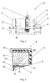
FIG. 1 is a schematic view of a CT apparatus according to an embodiment of the present invention; -
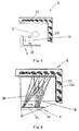
FIG. 2 is a schematic view showing layout of a ray source, a detector, and a correction device according to an embodiment of the present invention; -
FIG. 3 is a schematic view showing layout of the ray source and the detector according to an embodiment of the present invention; -
FIG. 4 is a schematic view showing layout of the ray source and the detector according to an embodiment of the present invention; -
FIG. 5 is a schematic view showing layout of the ray source and the detector according to an embodiment of the present invention; and -
FIG. 6 is a schematic view showing layout of the ray source and the detector according to an embodiment of the present invention. - A further description of the invention will be made as below with reference to embodiments of the present invention taken in conjunction with the accompanying drawings.
- As shown in
FIGS. 1-6 , aCT apparatus 10 according to an embodiment of the present invention comprises: ascanning passage 4; astationary X-ray source 7 including a plurality of ray emissionfocal spots 71; and a plurality ofstationary detector modules 12 disposed opposite theX-ray source 7, and at least some of thedetector modules 12 are arranged in a substantially L shape (FIGS. 2-4 and6 ) or a substantially Π shape (FIG. 5 ) when viewed in a plane intersecting thescanning passage 4. The plane may be substantially perpendicular to thescanning passage 4 or a transfer direction of the transfer device 1, or at an angle with respect to thescanning passage 4 or the transfer direction of the transfer device 1. The plurality of ray emissionfocal spots 71 and the plurality ofdetector modules 12 are arranged around thescanning passage 4. TheCT apparatus 10 may further comprise adetector arm 5 for fixing thedetector modules 12, anacquisition control unit 6, acomputer reconstruction unit 8, and the transfer device 1 for transferring anobject 2 under inspection. Thedetector arm 5 may has a substantially L shape (FIGS. 2-4 and6 ) or a substantially Π shape (FIG. 5 ). The plurality of ray emissionfocal spots 71 may be formed in an array by a single row of ray emission focal spots or a plurality of rows of ray emission focal spots. Alternatively, thedetector modules 12 may also be arranged in any other shape such as a semicircular shape, a U shape, an arc shape, and a parabolic shape. - The
X-ray source 7 may be a carbon nanotube X-ray source. At least some of the plurality of ray emissionfocal spots 71 of theX-ray source 7 are arranged in a substantially L shape (FIG 3 ), Π shape, or straight line shape (FIGS. 2 and4-6 ) when viewed in a plane intersecting the scanning passage. The plane may be substantially perpendicular to thescanning passage 4 or the transfer direction of the transfer device 1, or at an angle with respect to thescanning passage 4 or the transfer direction of the transfer device 1, and may be the above plane or different from the above plane. As shown inFIG 2 , a range covered by all of the sectorial X-ray beams emitted by the different ray emissionfocal spots 71 of theX-ray source 7 satisfies that aneffective scanning area 13 in thescanning passage 4 can all be covered by the X-ray beams. Emission of the X-ray of each ray emission focal spot of the X-ray source is controlled by theacquisition control unit 6, and time when the X-ray emissionfocal spots 71 emit X-rays and an intensity of the X-ray are adjustable. In addition, theX-ray source 7 may also be any other appropriate X-ray source so long as it includes a plurality of controllable ray emission focal spots. - As shown in
FIGS. 2-5 , eachdetector module 12 has aray receiving surface 121, and theray receiving surfaces 121 of the plurality ofdetector modules 12 abut against one another end to end such that rays emitted from the plurality of ray emissionfocal spots 71 cannot pass between the ray receivingsurfaces 121. On thedetector arm 5, thedetector modules 12 abut against one another end to end such that there is not a gap between the ray receiving surfaces and the ray receiving surfaces do not overlap one another in an orientation of the ray beams. The plurality ofdetector modules 12 may be arranged in a surface array or a linear array. - As shown in
FIG. 2 , the ray emissionfocal spots 71 are arranged in one row (which may be a curve-shaped row or an L-shaped row) or in a straight line when viewed in a plane intersecting thescanning passage 4, and elongation lines ofexternal sides focal spots intersection 15, and a line formed by connecting the point ofintersection 15 to a central point of theray receiving surface 121 of one of thedetector modules 12 is perpendicular to theray receiving surface 121 of the one of thedetector modules 12, when viewed in the plane intersecting thescanning passage 4. The plane may be substantially perpendicular to thescanning passage 4 or the transfer direction of the transfer device 1, or at an angle with respect to thescanning passage 4 or the transfer direction of the transfer device 1. - The plurality of
detector modules 12 may be arranged substantially in the shape of a spatial helix, and the plurality of ray emission focal spots of the X-ray source may also be arranged substantially in the shape of a spatial helix. Among the plurality of ray emissionfocal spots 71 of the X-ray source and the plurality ofdetector modules 12, the corresponding ray emission focal spots and detector modules may be arranged in the same plane. The plane may be substantially perpendicular to thescanning passage 4 or the transfer direction of the transfer device 1, or at an angle with respect to thescanning passage 4 or the transfer direction of the transfer device 1. - Each
detector module 12 can receive a ray from at least one of the plurality of ray emissionfocal spots 71 of theX-ray source 7. - As shown in
FIGS. 2-6 , the ray emissionfocal spots 71 and thedetector modules 12 are arranged in one plane when viewed in a plane intersecting thescanning passage 4, and the plane may be substantially perpendicular to the transfer direction of the transfer device 1, or at an angle with respect to the transfer direction of the transfer device 1. The plurality of ray emissionfocal spots 71 are arranged in one row and the plurality ofdetector modules 12 are arranged in at least one row in the transfer direction of the transfer device. As shown inFIG. 6 , the plurality of ray emissionfocal spots 71 may be arranged in two or more rows, and the plurality ofdetector modules 12 may be arranged in two or more rows. - As shown in
FIG. 2 , the CT apparatus according to the present invention further comprises: acorrection device 11 disposed between the plurality of ray emissionfocal spots 71 and the plurality ofdetector modules 12 for controlling doses of ray beams from the ray emission focal spots. Thecorrection device 11 may be a correction grid. A distance between the correction grid and theray receiving surfaces 121 of thedetector 12 is at least five times as large as a distance between the correction grid and the ray emissionfocal spots 71. - As shown in
FIG. 3 , in the CT apparatus with a stationary gantry in which thedetector arm 5 has an L-shaped structure, or thedetector modules 12 are arranged in an L shape, the ray emissionfocal spots 71 of theX-ray source 7 may also be arranged in an L shape. - In a period of time, X-ray energy reaching the
ray receiving surfaces 121 of thedetector 12 on thedetector arm 5 may come from a single ray emissionfocal spot 71 of theX-ray source 7, or from a ray combination of several ray emissionfocal spots 71 of theX-ray source 7. The intensities of the X-rays emitted from the different ray emissionfocal spots 71 of theX-ray source 7 may be program-controllable. A number of the ray emission focal spots of theX-ray source 7 correlates with a size of theeffective scanning area 13 within thescanning passage 4. The X-ray beams emitted from all of the ray emissionfocal spots 71 should cover the effective scanning area in thescanning passage 4. - A ray emitting manner of each X-ray emission
focal spot 71 of theX-ray source 7 correlates with an acquisition control manner of the CT apparatus with a stationary gantry, and whether each ray emissionfocal spot 71 is triggered or not is controlled by theacquisition control unit 6 of the CT apparatus. The ray emissionfocal spots 71 of theX-ray source 7 may emit X-rays in sequence by instructions of theacquisition control unit 6, and the intervals and frequency at which the ray emissionfocal spots 71 emit the rays are controlled by the instructions of theacquisition control unit 6. The ray emissionfocal spots 71 of theX-ray source 7 may also emit X-rays at intervals or the ray emissionfocal spots 71 of theX-ray source 7 may also emit X-rays under program control. - A plane in which the
detector arm 5 or thedetector modules 12 and the ray emissionfocal spots 71 of theX-ray source 7 are located may be perpendicular to the scanning passage, thedetector arm 5 or thedetector modules 12 and the ray emissionfocal spots 71 of theX-ray source 7 may also be arranged in the shape of a spatial curve such as a spatial helix, and thedetector modules 12 and theX-ray source 7 are arranged around theeffective scanning area 13 of thescanning passage 4. - The plurality of
detector module 12 are mounted to thedetector arm 5, and may form an arc-shaped region around thescanning passage 4. A row or a plurality of rows ofdetector modules 12 may be mounted to eachdetector arm 5. The number of rows of thedetector modules 12 on thedetector arm 5 correlates with a scanning speed of theCT apparatus 10. The number of rows of thedetector modules 12 may be less than or equal to 3 when the scanning speed is low (generally a moving speed of the transfer device 1 is less than 0.25m/s), and the number of rows of thedetector modules 12 may be greater than or equal to 5 or surface-array detector modules are used when the scanning speed is high (generally the moving speed of the transfer device 1 is larger than 0.3m/s). - The
detector modules 12 are mounted to thedetector arm 5 and supported and fixed by thedetector arm 5. A seal formed of a light-weight material is mounted at a portion, facing theX-ray source 7, of thedetector arm 5 to block dust and foreign matter in thescanning passage 4 from entering thedetector arm 5. - The linear
array detector modules 12 or surface-array detector modules 12' may be mounted to thestationary detector arm 5. The number and distribution manner of the detector modules correlate with a length of theX-ray source 7 and distribution and orientation of the plurality of ray emissionfocal spots 71. The detector modules and theX-ray source 7 can ensure that theeffective scanning area 13 in thescanning passage 4 is all covered by the X-ray beams. - In the
CT apparatus 10 with a stationary gantry which has theX-ray source 7 with the plurality of ray emissionfocal spots 71, theacquisition control unit 6 performs control, including control of theX-ray source 7, control of thedetector modules 12 and control of the computer reconstruction system, through a Controller Area Network (CAN) bus. Theacquisition control unit 6 provides support for communication protocol, control redundancy, and emergency control. By parsing the instructions of theacquisition control unit 6, a control unit in thedetector module 12 sends instructions for beginning data acquisition and transmits and error-corrects the acquired data, and the data acquired by the detector modules are transmitted to thecomputer reconstruction unit 8. - The
computer reconstruction unit 8 is a key device for achieving parsing and reconstruction of the data and characteristic identification in the gantry-less CT apparatus. When the acquired data are transmitted to thecomputer reconstruction unit 8, thecomputer reconstruction unit 8 firstly classifies the data according to the formats of the data packages, determines the sources of the data, and establishes a characteristic matrix based on the baggage scanned in the scanning area, and then solves the characteristic matrix to find a corresponding characteristic value. By comparing the characteristic value with a characteristic value of special substance in a data bank, thecomputer reconstruction unit 8 judges whether the substance in the baggage is a substance to which special attention should be paid and further provides a prompt about whether an alarm is raised. - The function of the
scanning passage 4 is to provide a passage in which the scannedbaggage 2 is transferred and travels, and a shield wall for shielding irrelevant X-rays. The radiation shielding material is a heavy metal such as lead, steal or other materials. - During inspection, the
baggage 2 under inspection is transferred into thescanning passage 4 at a speed by the belt of the transfer device 1. When thebaggage 2 triggers aphotoelectric sensor 3, theX-ray source 7 is brought into a state ready for emission. When thebaggage 2 enters theeffective scanning area 13, theacquisition control unit 6 controls the ray emissionfocal spots 71 of theX-ray source 7 to emit electronic beams so as to generate X-rays continuously or at intervals. Meanwhile, theacquisition control unit 6 sends instructions for beginning data acquisition so that thedetector modules 12 at the corresponding positions begin acquiring data. At the same time, time when the data are acquired and the positions of thedetector modules 12 that acquire the data are recorded. The acquired data are transmitted to thecomputer reconstruction unit 8 through a dedicated cable. Thecomputer reconstruction unit 8 corrects energy values of the X-rays by comparing instruction information for controlling the ray emission focal spot and acquired data information which occur within the same moment with each other, and then the data at the corresponding position of the baggage are reconstructed to establish a matrix based on substance characteristic of the scannedbaggage 2. The matrix is conversely solved by thecomputer reconstruction unit 8 to obtain a single or a plurality of substance characteristics of the scannedbaggage 2 at the corresponding position and establish the substance characteristic data within a single slice position. As thebaggage 2 moves at a speed, thecomputer reconstruction unit 8 will acquire the substance characteristic data of the entire baggage slice by slice. By a dedicated identification algorithm, the data characteristics of the slices are collectively analyzed and determined and compared with a substance characteristic table in an existing data bank, to obtain a conclusion about whether or not thebaggage 2 under inspection contains a special substance concerned by a user and display an image of the baggage by adisplay 81 of thecomputer reconstruction unit 8. - In the present invention, the X-ray beams 19 and 20 emitted at different times are generated and data are acquired by switching among the ray emission focal spots and among scanning and acquiring areas by switching among the ray emission
focal spots 71 of theX-ray source 7 which are located at respective positions. As a result, a computerized tomography scan of the baggage under inspection can be achieved by effectively utilizing the conventional computerized tomography (CT) technology without rotation of the object or rotation of thedetector arm 5 and theX-ray source 7. - During reconstruction by the computer, an accuracy of the reconstruction of the tomography or slice data by the computer correlates with an angle at which the scanned baggage is observed. The present invention can adopt the X-ray source based on the carbon nanotube. Therefore, the ray emission focal spots may be arranged at the same intervals over a length. A sequence in which the ray emission focal spots emit rays may be arranged along a straight line (as shown by the
arrows 16 inFIGS. 2-5 ) or a curve by program control performed by theacquisition control unit 6. A sequence in which the ray emission focal spots of the surface-array X-ray source 7' emit rays is arranged along acurve 22, and thecurve 22 may be a spatial helix, and thus it is possible to improve a reconstruction accuracy of the system to the most degree. - The scanned baggage may pass through the scanning area at a speed, or may remain stationary within the scanning area until the scanning is completed. The computer system distinguishes substances by identifying the substance characteristics of the slices of the baggage. The substance characteristic is not limited to one type of characteristic, and may be a density and an atomic member.
- The CT apparatus of the present invention can calculate and analyze the tomography or slice data at a higher rate, thereby providing an effective basis for a high-speed safety inspection CT system.
Claims (15)
- A stationary CT apparatus, comprising:a scanning passage;a stationary X-ray source arranged around the scanning passage and comprising a plurality of ray emission focal spots; anda plurality of stationary detector modules arranged around the scanning passage and disposed opposite the X-ray source.
- The stationary CT apparatus of claim 1, wherein
at least some of the plurality of ray emission focal spots of the X-ray source are arranged in a substantially L shape, Π shape, or straight line shape when viewed in a plane intersecting the scanning passage. - The stationary CT apparatus of claim 1, wherein
each detector module has a ray receiving surface, and the ray receiving surfaces of the plurality of detector modules abut against one another end to end such that rays emitted from the plurality of ray emission focal spots cannot pass between the ray receiving surfaces. - The stationary CT apparatus of claim 1 or 2, wherein
at least some of the plurality of detector modules are arranged in a substantially L shape or a substantially Π shape when viewed in a plane intersecting the scanning passage. - The stationary CT apparatus of claim 2 or 4, wherein
the plane is substantially perpendicular to the scanning passage or the plane is inclined with respect to the scanning passage. - The stationary CT apparatus of claim 4, wherein
the plurality of ray emission focal spots of the X-ray source are arranged in a straight line shape. - The stationary CT apparatus of claim 1, wherein
the plurality of detector modules are arranged substantially in the shape of a spatial helix. - The stationary CT apparatus of claim 1, wherein
the plurality of ray emission focal spots of the X-ray source are arranged substantially in the shape of a spatial helix. - The stationary CT apparatus of claim 1, wherein
among the plurality of ray emission focal spots of the X-ray source and the plurality of detector modules, the corresponding ray emission focal spots and detector modules are arranged in the same plane, and the plane is substantially perpendicular to the scanning passage or the plane is inclined with respect to the scanning passage. - The stationary CT apparatus of claim 1, wherein
each detector module can receive a ray beam from at least one of the plurality of ray emission focal spots of the X-ray source. - The stationary CT apparatus of claim 1, wherein
the plurality of ray emission focal spots are arranged in at least one row in a direction in which an object under inspection enters and leaves the scanning passage. - The stationary CT apparatus of claim 1, wherein
the plurality of detector modules are arranged in at least one row in a direction in which an object under inspection enters and leaves the scanning passage. - The stationary CT apparatus of claim 1, further comprising:a correction device disposed between the plurality of ray emission focal spots and the plurality of detector modules for controlling doses of ray beams from the ray emission focal spots, andwherein the correction device is a grid device made of a W-Ni-Fe alloy; andwherein a distance between the correction device and ray receiving surfaces of the detector modules is at least five times as large as a distance between the correction device and the ray emission focal spots.
- The stationary CT apparatus of claim 1, wherein
the X-ray source is a carbon nanotube X-ray source. - The stationary CT apparatus of claim 1, wherein a control of the plurality of ray emission focal spots of the X-ray source is achieved by a Controller Area Network (CAN) bus, and the ray emission focal spots may be arranged at the same intervals over a length, and a sequence in which the ray emission focal spots emit rays may be arranged along a straight line or a curve.
Applications Claiming Priority (1)
| Application Number | Priority Date | Filing Date | Title |
|---|---|---|---|
| CN201210581446.9A CN103901488A (en) | 2012-12-27 | 2012-12-27 | Fixed type CT apparatus |
Publications (1)
| Publication Number | Publication Date |
|---|---|
| EP2749872A1 true EP2749872A1 (en) | 2014-07-02 |
Family
ID=49876432
Family Applications (1)
| Application Number | Title | Priority Date | Filing Date |
|---|---|---|---|
| EP13198625.9A Ceased EP2749872A1 (en) | 2012-12-27 | 2013-12-19 | Stationary CT apparatus |
Country Status (8)
| Country | Link |
|---|---|
| US (1) | US9453937B2 (en) |
| EP (1) | EP2749872A1 (en) |
| JP (1) | JP5782101B2 (en) |
| CN (1) | CN103901488A (en) |
| DE (1) | DE202013105830U1 (en) |
| GB (1) | GB2509399B (en) |
| RU (1) | RU2566525C2 (en) |
| WO (1) | WO2014101391A1 (en) |
Cited By (2)
| Publication number | Priority date | Publication date | Assignee | Title |
|---|---|---|---|---|
| EP3236246B1 (en) * | 2014-12-17 | 2022-08-03 | Nuctech Company Limited | Radiation imaging system based on distributed light source |
| EP4369058A4 (en) * | 2021-07-07 | 2025-06-18 | Nuctech Company Limited | INSPECTION SYSTEM AND PROCEDURES |
Families Citing this family (15)
| Publication number | Priority date | Publication date | Assignee | Title |
|---|---|---|---|---|
| CN103674979B (en) * | 2012-09-19 | 2016-12-21 | 同方威视技术股份有限公司 | A kind of luggage and articles CT safe examination system and detector assembly thereof |
| CN105116462A (en) * | 2015-09-08 | 2015-12-02 | 同方威视技术股份有限公司 | Safety inspection apparatus |
| JP6576373B2 (en) * | 2017-01-30 | 2019-09-18 | 日本信号株式会社 | X-ray inspection device and baggage inspection device |
| CN108267776B (en) * | 2018-02-02 | 2024-11-08 | 张岚 | Multilayer detector structure and method for improving low-energy and medium-energy ray detection capabilities |
| CN108333620B (en) * | 2018-02-26 | 2023-08-15 | 张岚 | Detection device and positioning method of medium-low energy ray source |
| CN111265231B (en) * | 2019-04-15 | 2021-08-31 | 清华大学 | Distributed light source CT image reconstruction method and system |
| CN113133772A (en) * | 2020-01-20 | 2021-07-20 | 上海交通大学 | PET-CT system and scanning method |
| CN114167507B (en) * | 2020-09-11 | 2023-07-11 | 同方威视技术股份有限公司 | Multi-channel static CT device |
| FR3115452B1 (en) * | 2020-10-26 | 2024-06-21 | Thales Sa | Radiology device with sources and detector arranged in a helix |
| CN121762593A (en) * | 2021-07-07 | 2026-03-31 | 清华大学 | Ray scanning apparatus |
| CN115097538A (en) * | 2021-07-07 | 2022-09-23 | 同方威视技术股份有限公司 | Ray scanning apparatus and ray scanning system |
| CN114324425A (en) * | 2022-01-04 | 2022-04-12 | 北京航星机器制造有限公司 | A multi-view static CT system |
| CN114563428B (en) * | 2022-03-09 | 2025-08-01 | 河南省科学院同位素研究所有限责任公司 | Corrosion positioning non-contact evaluation system for steel structure in high-altitude enclosed space |
| CN120276059A (en) * | 2023-11-09 | 2025-07-08 | 清华大学 | Linear scanning CT imaging system and method |
| CN119510463B (en) * | 2024-11-29 | 2026-04-28 | 同方威视技术股份有限公司 | Material identification method and material identification device |
Citations (7)
| Publication number | Priority date | Publication date | Assignee | Title |
|---|---|---|---|---|
| WO1997018462A1 (en) * | 1995-11-13 | 1997-05-22 | The United States Of America As Represented By The | Apparatus and method for automatic recognition of concealed objects using multiple energy computed tomography |
| US20020094064A1 (en) * | 2000-10-06 | 2002-07-18 | Zhou Otto Z. | Large-area individually addressable multi-beam x-ray system and method of forming same |
| EP1371970A2 (en) * | 2002-06-12 | 2003-12-17 | Agilent Technologies, Inc. | Method and apparatus of 3D X-ray imaging for high speed scanning of large articles |
| US20050111610A1 (en) * | 2003-11-26 | 2005-05-26 | General Electric Company | Stationary computed tomography system and method |
| US20080025461A1 (en) * | 2006-02-09 | 2008-01-31 | L-3 Communications Security and Detection Systems Inc. | Tomographic imaging systems and methods |
| US20090285353A1 (en) * | 2008-05-19 | 2009-11-19 | Reveal Imaging Technologies, Inc. | Array CT |
| WO2013078344A1 (en) * | 2011-11-22 | 2013-05-30 | Xinray Systems Inc | High speed, small footprint x-ray tomography inspection systems, devices, and methods |
Family Cites Families (21)
| Publication number | Priority date | Publication date | Assignee | Title |
|---|---|---|---|---|
| DE3530938A1 (en) * | 1985-08-29 | 1987-03-12 | Heimann Gmbh | LUGGAGE TEST SYSTEM |
| US5581592A (en) * | 1995-03-10 | 1996-12-03 | General Electric Company | Anti-scatter X-ray grid device for medical diagnostic radiography |
| US6018562A (en) * | 1995-11-13 | 2000-01-25 | The United States Of America As Represented By The Secretary Of The Army | Apparatus and method for automatic recognition of concealed objects using multiple energy computed tomography |
| US5644614A (en) * | 1995-12-21 | 1997-07-01 | General Electric Company | Collimator for reducing patient x-ray dose |
| US6236709B1 (en) * | 1998-05-04 | 2001-05-22 | Ensco, Inc. | Continuous high speed tomographic imaging system and method |
| US7082182B2 (en) * | 2000-10-06 | 2006-07-25 | The University Of North Carolina At Chapel Hill | Computed tomography system for imaging of human and small animal |
| GB0525593D0 (en) * | 2005-12-16 | 2006-01-25 | Cxr Ltd | X-ray tomography inspection systems |
| US7340033B2 (en) * | 2003-07-30 | 2008-03-04 | Koninklijke Philips Electronics, N.V. | X-ray unit having an automatically adjustable collimator |
| US20050117700A1 (en) * | 2003-08-08 | 2005-06-02 | Peschmann Kristian R. | Methods and systems for the rapid detection of concealed objects |
| US20050078861A1 (en) * | 2003-10-10 | 2005-04-14 | Usikov Daniel A. | Tomographic system and method for iteratively processing two-dimensional image data for reconstructing three-dimensional image data |
| CN101467071B (en) * | 2006-04-21 | 2012-06-13 | 美国科技工程公司 | X-ray imaging of baggage and personnel using arrays of discrete sources and multiple collimated beams |
| CN101339147B (en) * | 2007-07-02 | 2012-03-28 | 清华大学 | Radiation image-forming system |
| WO2009050626A1 (en) * | 2007-10-19 | 2009-04-23 | Koninklijke Philips Electronics N.V. | Imaging system with distributed sources and detectors |
| JP5046874B2 (en) * | 2007-11-14 | 2012-10-10 | キヤノン株式会社 | Radiation image capturing apparatus and radiation image capturing method |
| CN101561405B (en) * | 2008-04-17 | 2011-07-06 | 清华大学 | Straight-line track scanning imaging system and method |
| JP5677301B2 (en) * | 2008-09-10 | 2015-02-25 | アナロジック コーポレーション | Computed tomography scanning system and method using multiple pixel x-ray sources |
| US9095259B2 (en) * | 2009-12-04 | 2015-08-04 | Analogic Corporation | Method and system for high resolution nutated slice reconstruction using quarter detector offset |
| JP2012034848A (en) * | 2010-08-06 | 2012-02-23 | Toshiba Corp | X-ray detector and x-ray ct scanner |
| US20110299653A1 (en) * | 2010-12-15 | 2011-12-08 | General Electric Company | Method and apparatus for laminography inspection |
| CN203012155U (en) * | 2012-12-27 | 2013-06-19 | 同方威视技术股份有限公司 | Rackless CT device |
| CN203084216U (en) * | 2012-12-27 | 2013-07-24 | 同方威视技术股份有限公司 | Fixed ct device |
-
2012
- 2012-12-27 CN CN201210581446.9A patent/CN103901488A/en active Pending
-
2013
- 2013-07-15 WO PCT/CN2013/079380 patent/WO2014101391A1/en not_active Ceased
- 2013-12-19 JP JP2013262620A patent/JP5782101B2/en active Active
- 2013-12-19 EP EP13198625.9A patent/EP2749872A1/en not_active Ceased
- 2013-12-19 GB GB1322557.8A patent/GB2509399B/en active Active
- 2013-12-19 DE DE202013105830.0U patent/DE202013105830U1/en not_active Expired - Lifetime
- 2013-12-24 US US14/140,058 patent/US9453937B2/en active Active
- 2013-12-25 RU RU2013157871/14A patent/RU2566525C2/en active
Patent Citations (7)
| Publication number | Priority date | Publication date | Assignee | Title |
|---|---|---|---|---|
| WO1997018462A1 (en) * | 1995-11-13 | 1997-05-22 | The United States Of America As Represented By The | Apparatus and method for automatic recognition of concealed objects using multiple energy computed tomography |
| US20020094064A1 (en) * | 2000-10-06 | 2002-07-18 | Zhou Otto Z. | Large-area individually addressable multi-beam x-ray system and method of forming same |
| EP1371970A2 (en) * | 2002-06-12 | 2003-12-17 | Agilent Technologies, Inc. | Method and apparatus of 3D X-ray imaging for high speed scanning of large articles |
| US20050111610A1 (en) * | 2003-11-26 | 2005-05-26 | General Electric Company | Stationary computed tomography system and method |
| US20080025461A1 (en) * | 2006-02-09 | 2008-01-31 | L-3 Communications Security and Detection Systems Inc. | Tomographic imaging systems and methods |
| US20090285353A1 (en) * | 2008-05-19 | 2009-11-19 | Reveal Imaging Technologies, Inc. | Array CT |
| WO2013078344A1 (en) * | 2011-11-22 | 2013-05-30 | Xinray Systems Inc | High speed, small footprint x-ray tomography inspection systems, devices, and methods |
Cited By (3)
| Publication number | Priority date | Publication date | Assignee | Title |
|---|---|---|---|---|
| EP3236246B1 (en) * | 2014-12-17 | 2022-08-03 | Nuctech Company Limited | Radiation imaging system based on distributed light source |
| EP4369058A4 (en) * | 2021-07-07 | 2025-06-18 | Nuctech Company Limited | INSPECTION SYSTEM AND PROCEDURES |
| US12699202B2 (en) | 2021-07-07 | 2026-08-04 | Nuctech Company Limited | Inspection system and inspection method |
Also Published As
| Publication number | Publication date |
|---|---|
| WO2014101391A1 (en) | 2014-07-03 |
| CN103901488A (en) | 2014-07-02 |
| JP2014130142A (en) | 2014-07-10 |
| US20140185743A1 (en) | 2014-07-03 |
| JP5782101B2 (en) | 2015-09-24 |
| GB2509399B (en) | 2016-01-06 |
| US9453937B2 (en) | 2016-09-27 |
| DE202013105830U1 (en) | 2014-01-31 |
| RU2013157871A (en) | 2015-09-10 |
| GB201322557D0 (en) | 2014-02-05 |
| RU2566525C2 (en) | 2015-10-27 |
| GB2509399A (en) | 2014-07-02 |
Similar Documents
| Publication | Publication Date | Title |
|---|---|---|
| US9453937B2 (en) | Stationary CT apparatus | |
| EP2749905B1 (en) | CT apparatus without gantry | |
| EP2899537B1 (en) | Luggage ct safety inspection system and detector device thereof | |
| JP6255369B2 (en) | Detector device, dual energy CT system, and detection method using the system | |
| US20090262891A1 (en) | Linear track scanning imaging system and method | |
| CN203084216U (en) | Fixed ct device | |
| EP2221847B1 (en) | X-ray diffraction imaging system, and method for fabricating the x-ray diffraction imaging system | |
| CN101382508A (en) | Apparatus and method for inspecting prohibited items in an air cargo container | |
| JP6078506B2 (en) | A tomographic scanner based on a linear trajectory. | |
| CN101382507A (en) | A device for checking prohibited items in an air cargo container | |
| WO2025098095A1 (en) | Ct scanning system and method | |
| CN203012155U (en) | Rackless CT device | |
| CN202794067U (en) | Luggage CT safety inspection system and detector device thereof | |
| EP4300083A1 (en) | Imaging system for radiographic examination | |
| WO2025098141A1 (en) | Ct scanning system | |
| KR20250120317A (en) | Straight scan CT imaging system and method | |
| EP2378280A1 (en) | X-ray inspection method and x-ray inspection apparatus | |
| JPH06265485A (en) | Fluoroscope | |
| CN211978725U (en) | A safety detection device | |
| JP6523451B2 (en) | Radiation detector and X-ray CT apparatus equipped with the same | |
| US20190350539A1 (en) | Image reconstruction for z-flying focal spot tomography | |
| HK1195812A (en) | Stationary ct apparatus | |
| HK1195941B (en) | A ct apparatus without a gantry | |
| HK1195941A (en) | A ct apparatus without a gantry | |
| CN121994836A (en) | Linear CT imaging system and scanning imaging method based on multi-section linear track |
Legal Events
| Date | Code | Title | Description |
|---|---|---|---|
| 17P | Request for examination filed |
Effective date: 20131219 |
|
| AK | Designated contracting states |
Kind code of ref document: A1 Designated state(s): AL AT BE BG CH CY CZ DE DK EE ES FI FR GB GR HR HU IE IS IT LI LT LU LV MC MK MT NL NO PL PT RO RS SE SI SK SM TR |
|
| AX | Request for extension of the european patent |
Extension state: BA ME |
|
| PUAI | Public reference made under article 153(3) epc to a published international application that has entered the european phase |
Free format text: ORIGINAL CODE: 0009012 |
|
| 17Q | First examination report despatched |
Effective date: 20160212 |
|
| STAA | Information on the status of an ep patent application or granted ep patent |
Free format text: STATUS: EXAMINATION IS IN PROGRESS |
|
| APBK | Appeal reference recorded |
Free format text: ORIGINAL CODE: EPIDOSNREFNE |
|
| APBN | Date of receipt of notice of appeal recorded |
Free format text: ORIGINAL CODE: EPIDOSNNOA2E |
|
| APBR | Date of receipt of statement of grounds of appeal recorded |
Free format text: ORIGINAL CODE: EPIDOSNNOA3E |
|
| APAF | Appeal reference modified |
Free format text: ORIGINAL CODE: EPIDOSCREFNE |
|
| APBT | Appeal procedure closed |
Free format text: ORIGINAL CODE: EPIDOSNNOA9E |
|
| STAA | Information on the status of an ep patent application or granted ep patent |
Free format text: STATUS: THE APPLICATION HAS BEEN REFUSED |
|
| 18R | Application refused |
Effective date: 20211207 |