EP2749825A2 - Cooling device with a sealing element - Google Patents
Cooling device with a sealing element Download PDFInfo
- Publication number
- EP2749825A2 EP2749825A2 EP13197940.3A EP13197940A EP2749825A2 EP 2749825 A2 EP2749825 A2 EP 2749825A2 EP 13197940 A EP13197940 A EP 13197940A EP 2749825 A2 EP2749825 A2 EP 2749825A2
- Authority
- EP
- European Patent Office
- Prior art keywords
- opening
- cooling device
- inner housing
- sealing element
- head portion
- Prior art date
- Legal status (The legal status is an assumption and is not a legal conclusion. Google has not performed a legal analysis and makes no representation as to the accuracy of the status listed.)
- Withdrawn
Links
- 238000007789 sealing Methods 0.000 title claims abstract description 30
- 238000001816 cooling Methods 0.000 title claims abstract description 20
- 239000000463 material Substances 0.000 claims description 5
- 229920001971 elastomer Polymers 0.000 claims description 4
- 230000000284 resting effect Effects 0.000 claims description 2
- 239000011810 insulating material Substances 0.000 description 7
- 238000004049 embossing Methods 0.000 description 5
- 238000000034 method Methods 0.000 description 3
- 239000006260 foam Substances 0.000 description 1
- 238000009413 insulation Methods 0.000 description 1
- 230000000670 limiting effect Effects 0.000 description 1
- 229920002635 polyurethane Polymers 0.000 description 1
- 239000004814 polyurethane Substances 0.000 description 1
- 239000003566 sealing material Substances 0.000 description 1
Images

Classifications
-
- F—MECHANICAL ENGINEERING; LIGHTING; HEATING; WEAPONS; BLASTING
- F25—REFRIGERATION OR COOLING; COMBINED HEATING AND REFRIGERATION SYSTEMS; HEAT PUMP SYSTEMS; MANUFACTURE OR STORAGE OF ICE; LIQUEFACTION SOLIDIFICATION OF GASES
- F25D—REFRIGERATORS; COLD ROOMS; ICE-BOXES; COOLING OR FREEZING APPARATUS NOT OTHERWISE PROVIDED FOR
- F25D23/00—General constructional features
-
- F—MECHANICAL ENGINEERING; LIGHTING; HEATING; WEAPONS; BLASTING
- F25—REFRIGERATION OR COOLING; COMBINED HEATING AND REFRIGERATION SYSTEMS; HEAT PUMP SYSTEMS; MANUFACTURE OR STORAGE OF ICE; LIQUEFACTION SOLIDIFICATION OF GASES
- F25D—REFRIGERATORS; COLD ROOMS; ICE-BOXES; COOLING OR FREEZING APPARATUS NOT OTHERWISE PROVIDED FOR
- F25D2400/00—General features of, or devices for refrigerators, cold rooms, ice-boxes, or for cooling or freezing apparatus not covered by any other subclass
- F25D2400/40—Refrigerating devices characterised by electrical wiring
Definitions
- the invention relates to a cooling device having a heat insulated body, an inner housing provided inside the body, an opening provided on a rear wall of the inner housing, and a sealing element having a neck portion provided on one side of the opening, a head portion provided on the other side of the opening, and a longitudinal gap provided on at least the head portion.
- a cooling device has within the heat insulated body an inner housing. Insulating material is filled between the inner housing and the body in order to provide heat insulation. Generally polyurethane is used as insulating material. The insulating material is filled from openings generated on the inner housing and conducting elements that can be used for various purposes pass also through these openings.
- a cooling device having a sealing element placed in the opening provided in the intermediate wall of the inner housing in its body.
- the invention is a cooling device having a heat insulated body; an inner housing surrounded by the body; a conducting element passed through an opening that possesses the inner housing and a sealing element encircling peripherally the conducting element passing through its hole and filling between the conducting element and the opening of the inner housing. It comprises a gap, which is generated lengthwise on a lateral side of the sealing element and which is dimensioned as spaced forms enabling the conducting element to pass through the hole when the sealing element is in a free state and which rests in the opening and presses so as to provide outwardly radial sealing when it is at least partially closed.
- the object of the invention is to put forth a cooling device with a sealing element, in which the area of the opening in its center can be adjusted to close the opening on the inner housing and which sealing functionality is improved.
- the present invention is a cooling device having a heat insulated body, an inner housing provided inside the body, an opening provided on a rear wall of the inner housing, and a sealing element having a neck portion provided on one side of the opening, a head portion provided on the other side of the opening, and a longitudinal gap provided on at least the head portion. Accordingly it comprises a clamp provided in belt form on one side of the gap and a lock arm extending so as to pass through the clamp from the other side of the gap. Thereby, the opening engaged by the conducting element is clamped.
- the cooling device comprises a flange resting onto the inner housing from the head portion side or the neck portion side of the opening. Thereby, a passage of the insulating material in the inner housing is prevented.
- the flange is split from a region so as to define two ends that can approach each other in an integrated manner while the gap is being closed. Thereby, sealing is provided by the movement of both ends of the flange when the head portion of the sealing element makes a clamping movement.
- the lock arm comprises pluralities of teeth embodied in ladder form on the face thereof facing an outer side of the clamp.
- fastening is provided by matching of the inner wall of the clamp and the straight portion of any tooth.
- a channel is extending along a wall of said opening provided in the middle of the head portion and of the neck portion.
- the sealing element is made of rubber material.
- cooling device (10) with a sealing element (20) is described with examples for the sole purpose of better understanding of the subject that do not have any limiting effect.
- a cooling device (10) has an inner housing (12) within the heat insulated body (11).
- An embossing form (131) is generated on the rear wall (13) of the inner housing (12).
- the embossing form (131) has on top a circular opening (132).
- Various conducting elements (14) can be passed through the circular opening (132).
- the sealing element (20) placed in the circular opening (132) has a body (21) with generally a cylindrical structure and an associated flange (26) extending circularly outwardly from the body (21) and its outer wall (23).
- Said flange (26) is embodied circularly and has a circular opening (not represented in the figure) such that the body (21) of the sealing element (20) passes through its center.
- the flange (26) and the body (21) are embodied as a single piece.
- the body (21) comprises a head portion (22) provided on the front side of the inner housing (12) of the flange (26) when passed through the opening in the middle of the flange (26) and a neck portion (24) provided on the other side of the flange (26).
- a circular opening (25) extending along the head portion (22) and the neck portion (24) is present in the middle of the body (21).
- a channel (252) extending along the body (21).
- the channel (252) is embodied in a transverse half cylinder-like form.
- the sealing element (20) is produced from rubber material.
- the head portion (22) has a clamping region (222) generated in a bulge form outwardly from its circular form and a straight gap (223) extending lengthwise starting from the top surface (221) of the head portion (22) is located in the clamping region (222).
- a clamp (224) is generated in belt form outwardly from the outer wall (23) of the head portion (22).
- the clamp (224) is in a hollow rectangle-like form.
- a lock arm (227) is generated, which passes through the clamp (224) starting from the edge of the clamping region (222) and extends with a defined angle out of the head portion (222) in a rectangle rod-like form.
- the lock arm (227) has pluralities of teeth (228) embodied in ladder form so as to face towards the outer side (225) of the clamp (224).
- the neck portion (24) is passed through the opening (132) and the side of the flange (26) facing the head portion (22) of the sealing element (20) is made to rest onto the rear wall (13) of the inner housing (12) from the back side of the inner housing (12).
- the flange (26) is provided on the side where the foam is pressed.
- the portion matched by the flange (26) can vary.
- Required conducting elements (14) are passed through the opening (25) of the sealing element (20) and the opening (25) is narrowed from the clamping region (222). As last process the insulating material is filled between the inner housing (12) and the body (11).
- the flange (26) associated with the body (21) prevents that insulating material escaping into the inner housing (12) through the opening (132) in the rear wall (13) of the inner housing (12) and the outer wall (23) of the sealing element (20). As the flange (26) rests onto the rear wall (13) of the inner housing (12), even if insulating material passes through the outer wall (23) of the sealing element (20) and the opening (132), its passage to the inner housing (12) is not allowed.
Landscapes
- Engineering & Computer Science (AREA)
- Chemical & Material Sciences (AREA)
- Combustion & Propulsion (AREA)
- Physics & Mathematics (AREA)
- Mechanical Engineering (AREA)
- Thermal Sciences (AREA)
- General Engineering & Computer Science (AREA)
- Cooling Or The Like Of Electrical Apparatus (AREA)
- Gasket Seals (AREA)
Abstract
Description
- The invention relates to a cooling device having a heat insulated body, an inner housing provided inside the body, an opening provided on a rear wall of the inner housing, and a sealing element having a neck portion provided on one side of the opening, a head portion provided on the other side of the opening, and a longitudinal gap provided on at least the head portion.
- A cooling device has within the heat insulated body an inner housing. Insulating material is filled between the inner housing and the body in order to provide heat insulation. Generally polyurethane is used as insulating material. The insulating material is filled from openings generated on the inner housing and conducting elements that can be used for various purposes pass also through these openings.
- In the application number
2012/06613 - The object of the invention is to put forth a cooling device with a sealing element, in which the area of the opening in its center can be adjusted to close the opening on the inner housing and which sealing functionality is improved.
- The present invention is a cooling device having a heat insulated body, an inner housing provided inside the body, an opening provided on a rear wall of the inner housing, and a sealing element having a neck portion provided on one side of the opening, a head portion provided on the other side of the opening, and a longitudinal gap provided on at least the head portion. Accordingly it comprises a clamp provided in belt form on one side of the gap and a lock arm extending so as to pass through the clamp from the other side of the gap. Thereby, the opening engaged by the conducting element is clamped.
- In a preferred configuration of the invention, the cooling device comprises a flange resting onto the inner housing from the head portion side or the neck portion side of the opening. Thereby, a passage of the insulating material in the inner housing is prevented.
- In another preferred configuration of the invention the flange is split from a region so as to define two ends that can approach each other in an integrated manner while the gap is being closed. Thereby, sealing is provided by the movement of both ends of the flange when the head portion of the sealing element makes a clamping movement.
- In another preferred configuration of the invention the lock arm comprises pluralities of teeth embodied in ladder form on the face thereof facing an outer side of the clamp. Thereby, fastening is provided by matching of the inner wall of the clamp and the straight portion of any tooth.
- In another preferred configuration of the invention a channel is extending along a wall of said opening provided in the middle of the head portion and of the neck portion. Thereby, it is provided that the conducting element of thin structure passes through the opening.
- In another preferred configuration of the invention the sealing element is made of rubber material. Thereby, due to the structure of the material in case there is no gap in the sealing material, a partial clamping process can be made by narrowing the opening.
-
- In
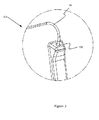
Figure 1 is given a representative view of the cooling device with the sealing element subject of the invention. - In
Figure 2 is given a representative view of the embossing form in the rear wall of the inner housing belonging to the cooling device subject of the invention. - In
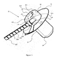
Figure 3 is given a representative view of the sealing element placed in the opening provided in the embossing form. - In this detailed description, the cooling device (10) with a sealing element (20) is described with examples for the sole purpose of better understanding of the subject that do not have any limiting effect.
- With reference to
Figure 1 and2 a cooling device (10) has an inner housing (12) within the heat insulated body (11). An embossing form (131) is generated on the rear wall (13) of the inner housing (12). The embossing form (131) has on top a circular opening (132). Various conducting elements (14) can be passed through the circular opening (132). - With reference to
Figure 3 the sealing element (20) placed in the circular opening (132) has a body (21) with generally a cylindrical structure and an associated flange (26) extending circularly outwardly from the body (21) and its outer wall (23). Said flange (26) is embodied circularly and has a circular opening (not represented in the figure) such that the body (21) of the sealing element (20) passes through its center. The flange (26) and the body (21) are embodied as a single piece. The body (21) comprises a head portion (22) provided on the front side of the inner housing (12) of the flange (26) when passed through the opening in the middle of the flange (26) and a neck portion (24) provided on the other side of the flange (26). A circular opening (25) extending along the head portion (22) and the neck portion (24) is present in the middle of the body (21). In the wall (251) of the opening is located a channel (252) extending along the body (21). The channel (252) is embodied in a transverse half cylinder-like form. The sealing element (20) is produced from rubber material. - The head portion (22) has a clamping region (222) generated in a bulge form outwardly from its circular form and a straight gap (223) extending lengthwise starting from the top surface (221) of the head portion (22) is located in the clamping region (222). In the vicinity of said gap (223) a clamp (224) is generated in belt form outwardly from the outer wall (23) of the head portion (22). The clamp (224) is in a hollow rectangle-like form. A lock arm (227) is generated, which passes through the clamp (224) starting from the edge of the clamping region (222) and extends with a defined angle out of the head portion (222) in a rectangle rod-like form. The lock arm (227) has pluralities of teeth (228) embodied in ladder form so as to face towards the outer side (225) of the clamp (224).
- When the sealing element (20) is associated to the opening (132) in the inner housing (12) the neck portion (24) is passed through the opening (132) and the side of the flange (26) facing the head portion (22) of the sealing element (20) is made to rest onto the rear wall (13) of the inner housing (12) from the back side of the inner housing (12). The flange (26) is provided on the side where the foam is pressed. In alternative embodiments, the portion matched by the flange (26) can vary. Required conducting elements (14) are passed through the opening (25) of the sealing element (20) and the opening (25) is narrowed from the clamping region (222). As last process the insulating material is filled between the inner housing (12) and the body (11). If it is needed to use a sealing element (14) of thin structure, it is extended from the channel (252) placed in the opening (25) of the sealing element (20). In the clamping process, there is a movement in the flange (26) also together with the head portion (22). The lock arm (227) retracts outwardly in the clamp (224) and the inner wall (226) of the clamp (224) matches with the straight portion (229) of one of the teeth (228) of the lock arm (227) and the lock arm (227) cannot move back.
- With reference to
Figure 3 the flange (26) associated with the body (21) prevents that insulating material escaping into the inner housing (12) through the opening (132) in the rear wall (13) of the inner housing (12) and the outer wall (23) of the sealing element (20). As the flange (26) rests onto the rear wall (13) of the inner housing (12), even if insulating material passes through the outer wall (23) of the sealing element (20) and the opening (132), its passage to the inner housing (12) is not allowed. - In an alternative embodiment, when no gap (223) is in question on the body (21), it is provided that the opening (25) is partially clamped due to the structure of the rubber material.
- The scope of protection of the invention is mentioned in the enclosed claims and can absolutely not be limited in this detailed statement to what is explained for exemplification purpose. Yet it is clear that a person skilled in the art can set forth similar configurations in the light of what is explained above without departing from the main theme of the invention.
-
- 10
- Cooling device
- 11
- Body
- 12
- Inner housing
- 13
- Rear wall
- 131
- Embossing form
- 132
- Opening
- 14
- Conducting element
- 20
- Sealing element
- 21
- Body
- 22
- Head portion
- 221
- Top surface
- 222
- Clamping region
- 223
- Gap
- 224
- Clamp
- 225
- Outer side
- 226
- Inner wall
- 227
- Lock arm
- 228
- Tooth
- 229
- Straight portion
- 23
- Outer wall
- 24
- Neck portion
- 25
- Opening
- 251
- Wall
- 252
- Channel
- 26
- Flange
Claims (6)
- A cooling device (10) having a heat insulated body (11), an inner housing (12) provided inside the body (11), an opening (132) provided on a rear wall (13) of the inner housing (12), and a sealing element (20) having a neck portion (24) provided on one side of the opening (132), a head portion (22) provided on the other side of the opening (132), and a longitudinal gap (223) provided on at least the head portion (22), characterized by comprising a clamp (224) provided in belt form on one side of the gap (223), and a lock arm (227) extending so as to pass through the clamp (224) from the other side of the gap (223).
- A cooling device according to Claim 1, wherein it comprises a flange (26) resting onto the inner housing (12) from the head portion (22) side or the neck portion (24) side of the opening (132).
- A cooling device according to Claim 2, wherein the flange (26) is split from a region so as to define two ends that can approach each other in an integrated manner while the gap (223) is being closed.
- A cooling device according to Claim 1, wherein the lock arm (227) comprises pluralities of teeth (228) embodied in ladder form on the face thereof facing an outer side (225) of the clamp (224).
- A cooling device according to Claim 1, wherein a channel (252) is extending along a wall (251) of said opening (25) provided in the middle of the head portion (22) and of the neck portion (24).
- A cooling device according to any one of the preceding claims, wherein the sealing element (20) is made of rubber material.
Applications Claiming Priority (1)
| Application Number | Priority Date | Filing Date | Title |
|---|---|---|---|
| TR201215770 | 2012-12-31 |
Publications (2)
| Publication Number | Publication Date |
|---|---|
| EP2749825A2 true EP2749825A2 (en) | 2014-07-02 |
| EP2749825A3 EP2749825A3 (en) | 2017-08-09 |
Family
ID=49765977
Family Applications (1)
| Application Number | Title | Priority Date | Filing Date |
|---|---|---|---|
| EP13197940.3A Withdrawn EP2749825A3 (en) | 2012-12-31 | 2013-12-18 | Cooling device with a sealing element |
Country Status (1)
| Country | Link |
|---|---|
| EP (1) | EP2749825A3 (en) |
Family Cites Families (5)
| Publication number | Priority date | Publication date | Assignee | Title |
|---|---|---|---|---|
| US4180297A (en) * | 1977-09-22 | 1979-12-25 | General Electric Company | Sealing grommet in a refrigerator cabinet |
| JPS60118477U (en) * | 1984-01-19 | 1985-08-10 | シャープ株式会社 | insulation box body |
| JP3651168B2 (en) * | 1997-03-19 | 2005-05-25 | 富士電機リテイルシステムズ株式会社 | Refrigerated / refrigerated showcase |
| JP2001056284A (en) * | 1999-08-20 | 2001-02-27 | Fukushima Industries Corp | Measurement hole cap |
| JP2001231143A (en) * | 2000-02-14 | 2001-08-24 | Sanyo Electric Co Ltd | Wiring device |
-
2013
- 2013-12-18 EP EP13197940.3A patent/EP2749825A3/en not_active Withdrawn
Also Published As
| Publication number | Publication date |
|---|---|
| EP2749825A3 (en) | 2017-08-09 |
Similar Documents
| Publication | Publication Date | Title |
|---|---|---|
| ATLAS Collaboration atlas. publications@ cern. ch et al. | Measurement of the top quark mass in the tt¯→ lepton+ jets and tt¯→ dilepton channels using s= 7 TeV ATLAS data | |
| DE50205224D1 (en) | Identification from ampoule | |
| WO2014158690A3 (en) | Apparatus for spinal fixation and methods of use | |
| BR112018077484A2 (en) | hemostatic instrument | |
| DK2289820T3 (en) | Capsule with relief-shaped sealing part | |
| WO2016059172A8 (en) | Caps for needles and catheters | |
| EP3698829A4 (en) | SAFE INJECTION DEVICE, SYRINGE, AND ASSEMBLY PROCEDURES FOR A SAFE INJECTION DEVICE | |
| IL275130A (en) | Device and needle module for puncturing skin | |
| MX2016011514A (en) | Hair styling device. | |
| CA2939791C (en) | Needle assisted jet injection administration of testosterone compositions | |
| US10573436B2 (en) | Liquid-tight strain relief | |
| UA117517C2 (en) | Inhaler | |
| SG11201906879TA (en) | Puncture instrument and puncture device | |
| MY152198A (en) | Needle safety device | |
| WO2015158978A8 (en) | Device for maintaining a user's vein in position and device for puncturing or injecting into a user's vein | |
| USD811976S1 (en) | Side rail protector bar | |
| WO2015089165A3 (en) | Flushable catheters | |
| HUE072174T2 (en) | Improved injection system and patient set assembly therefor | |
| EP3659657A4 (en) | Intradermal needle, packaged product thereof, and injection device | |
| US11071397B1 (en) | Stand for holding smart watch bands | |
| WO2017048992A8 (en) | Deployment devices and related assemblies and methods | |
| ZA202102425B (en) | Bedding assembly, duvet cover and fixation device | |
| MY209036A (en) | Application of chidamide in combination with r-chop, and drug combination | |
| WO2015169453A3 (en) | Device for fixating a kirschner wire | |
| PL3553536T3 (en) | Combination of a sensor module and a fuse, and use of a sensor module in the combination |
Legal Events
| Date | Code | Title | Description |
|---|---|---|---|
| 17P | Request for examination filed |
Effective date: 20131218 |
|
| AK | Designated contracting states |
Kind code of ref document: A2 Designated state(s): AL AT BE BG CH CY CZ DE DK EE ES FI FR GB GR HR HU IE IS IT LI LT LU LV MC MK MT NL NO PL PT RO RS SE SI SK SM TR |
|
| AX | Request for extension of the european patent |
Extension state: BA ME |
|
| PUAI | Public reference made under article 153(3) epc to a published international application that has entered the european phase |
Free format text: ORIGINAL CODE: 0009012 |
|
| RAP1 | Party data changed (applicant data changed or rights of an application transferred) |
Owner name: BSH HAUSGERAETE GMBH |
|
| PUAL | Search report despatched |
Free format text: ORIGINAL CODE: 0009013 |
|
| AK | Designated contracting states |
Kind code of ref document: A3 Designated state(s): AL AT BE BG CH CY CZ DE DK EE ES FI FR GB GR HR HU IE IS IT LI LT LU LV MC MK MT NL NO PL PT RO RS SE SI SK SM TR |
|
| AX | Request for extension of the european patent |
Extension state: BA ME |
|
| RIC1 | Information provided on ipc code assigned before grant |
Ipc: F25D 23/00 20060101AFI20170706BHEP |
|
| R17P | Request for examination filed (corrected) |
Effective date: 20180209 |
|
| RBV | Designated contracting states (corrected) |
Designated state(s): AL AT BE BG CH CY CZ DE DK EE ES FI FR GB GR HR HU IE IS IT LI LT LU LV MC MK MT NL NO PL PT RO RS SE SI SK SM TR |
|
| STAA | Information on the status of an ep patent application or granted ep patent |
Free format text: STATUS: THE APPLICATION IS DEEMED TO BE WITHDRAWN |
|
| 18D | Application deemed to be withdrawn |
Effective date: 20190702 |