EP2749797A1 - Seal device - Google Patents
Seal device Download PDFInfo
- Publication number
- EP2749797A1 EP2749797A1 EP12841052.9A EP12841052A EP2749797A1 EP 2749797 A1 EP2749797 A1 EP 2749797A1 EP 12841052 A EP12841052 A EP 12841052A EP 2749797 A1 EP2749797 A1 EP 2749797A1
- Authority
- EP
- European Patent Office
- Prior art keywords
- vertical wall
- wall portion
- rotational body
- seal device
- stationary body
- Prior art date
- Legal status (The legal status is an assumption and is not a legal conclusion. Google has not performed a legal analysis and makes no representation as to the accuracy of the status listed.)
- Withdrawn
Links
- 239000012530 fluid Substances 0.000 claims description 64
- 238000007789 sealing Methods 0.000 abstract description 8
- 238000011144 upstream manufacturing Methods 0.000 description 14
- 230000002238 attenuated effect Effects 0.000 description 9
- 238000010586 diagram Methods 0.000 description 2
- 230000003247 decreasing effect Effects 0.000 description 1
- 230000000694 effects Effects 0.000 description 1
- 238000000034 method Methods 0.000 description 1
- 230000002265 prevention Effects 0.000 description 1
Images



Classifications
-
- F—MECHANICAL ENGINEERING; LIGHTING; HEATING; WEAPONS; BLASTING
- F16—ENGINEERING ELEMENTS AND UNITS; GENERAL MEASURES FOR PRODUCING AND MAINTAINING EFFECTIVE FUNCTIONING OF MACHINES OR INSTALLATIONS; THERMAL INSULATION IN GENERAL
- F16J—PISTONS; CYLINDERS; SEALINGS
- F16J15/00—Sealings
- F16J15/44—Free-space packings
- F16J15/447—Labyrinth packings
-
- F—MECHANICAL ENGINEERING; LIGHTING; HEATING; WEAPONS; BLASTING
- F16—ENGINEERING ELEMENTS AND UNITS; GENERAL MEASURES FOR PRODUCING AND MAINTAINING EFFECTIVE FUNCTIONING OF MACHINES OR INSTALLATIONS; THERMAL INSULATION IN GENERAL
- F16J—PISTONS; CYLINDERS; SEALINGS
- F16J15/00—Sealings
- F16J15/44—Free-space packings
- F16J15/447—Labyrinth packings
- F16J15/4472—Labyrinth packings with axial path
-
- F—MECHANICAL ENGINEERING; LIGHTING; HEATING; WEAPONS; BLASTING
- F01—MACHINES OR ENGINES IN GENERAL; ENGINE PLANTS IN GENERAL; STEAM ENGINES
- F01D—NON-POSITIVE DISPLACEMENT MACHINES OR ENGINES, e.g. STEAM TURBINES
- F01D11/00—Preventing or minimising internal leakage of working-fluid, e.g. between stages
- F01D11/003—Preventing or minimising internal leakage of working-fluid, e.g. between stages by packing rings; Mechanical seals
-
- F—MECHANICAL ENGINEERING; LIGHTING; HEATING; WEAPONS; BLASTING
- F05—INDEXING SCHEMES RELATING TO ENGINES OR PUMPS IN VARIOUS SUBCLASSES OF CLASSES F01-F04
- F05D—INDEXING SCHEME FOR ASPECTS RELATING TO NON-POSITIVE-DISPLACEMENT MACHINES OR ENGINES, GAS-TURBINES OR JET-PROPULSION PLANTS
- F05D2240/00—Components
- F05D2240/55—Seals
Definitions
- the present invention relates to a seal device which prevents leakage of a fluid between a stationary side and a rotational side.
- a seal device is provided between the housing and the rotational body in order to prevent an axial leakage flow of the fluid between the housing and the rotational body.
- a labyrinth seal is generally applied as the seal device.
- the labyrinth seal is configured in such a manner that a plurality of seal fins are provided in at least one side of a stationary side such as the housing or a rotational body side to generate pressure loss by a clearance formed between the seal fin and the stationary side or the rotational body side and can suppress the axial leakage flow of the fluid by the pressure loss, thus performing a seal function.
- a plate is provided in a seal fin to suppress a swirling flow.
- it is difficult to effectively suppress the swirling flow, which occurs in a seal portion, only by providing the swirling flow suppressing plate in the seal fin.
- the invention is intended to solve the above-described problem and to provide a seal device which can suppress a flow between a stationary body and a rotational body to suppress an unstable vibration of the rotational body and improve sealing performance.
- the fluid flowing therebetween flows to the protrusion portion through the clearance between the first vertical wall portion and the stationary body or the rotational body and is guided to the protrusion portion to flow to an outer side in the radial direction and thus enter into the swirl breaker chamber; the axial center direction component and the swirling direction component of the fluid are attenuated by the swirl breaker chamber, and thus the fluid speed is reduced; and the flow between the stationary body and the rotational body can be suppressed, thereby it is possible to suppress the unstable vibration of the rotational body and improve the sealing performance.
- the swirl breaker chamber is provided at a downstream side from the first vertical wall portion of the uppermost stream side in a flow direction of the fluid flowing between the stationary body and the rotational body in the axial center direction of the rotational body.
- the swirl breaker chamber is provided at the downstream side from the first vertical wall portion, the fluid passing through the clearance between the first vertical wall portion and the stationary body or the rotational body appropriately flows to the swirl breaker chamber by the protrusion portion, thereby it is possible to attenuate the axial center direction component and the swirling direction component.
- the swirl breaker chamber is opened toward the protrusion portion and is also opened toward the first vertical wall portion of the uppermost stream side.
- the swirl breaker chamber is opened to the upstream side in the flow direction of the fluid, the fluid guided outward by the protrusion portion can appropriately flow to the swirl breaker chamber.
- a length in a radial direction of the protrusion portion is set to be not less than a clearance between a tip end of the first vertical wall portion and the stationary body or the rotational body in the radial direction.
- the fluid passing through the clearance between the first vertical wall portion and the stationary body or the rotational body is appropriately guided to the protrusion portion, and thus the fluid can flow to the swirl breaker chamber by the protrusion portion.
- a length in a circumferential direction of the swirl breaker chamber is set to be substantially equal to a distance between the swirl breaker chambers in the circumferential direction.
- the first vertical wall portion and the second vertical wall portion are provided in the stationary body side, the second vertical wall portion is set to be shorter than the first vertical wall portion in the radial direction, and the protrusion portion is arranged so as to face the second vertical wall portion.
- the first vertical wall portion and the second vertical wall portion are provided in the rotational body side, and the protrusion portion is provided at a tip end of the second vertical wall portion so that the second vertical wall portion is set to be longer than the first vertical wall portion in the radial direction.
- the seal device of the invention since the seal device is provided with the plurality of ring-shaped first vertical wall portions, the ring-shaped second vertical wall portion which is adjacent to the first vertical wall portions and is thicker than the first vertical wall portion in the axial center direction, the ring-shaped protrusion portion which corresponds to the second vertical wall portion and protrudes from the rotational body, and the plurality of swirl breaker chambers which are arranged in the stationary body at predetermined intervals in the circumferential direction so as to face the protrusion portion, the leakage flow between the stationary body and the rotational body is suppressed in the axial center direction and the swirling direction, thereby it is possible to suppress the unstable vibration of the rotational body and thus improve the sealing performance.
- FIG. 1 is a schematic view of a seal device according to a first embodiment of the invention
- FIG. 2 is a cross-sectional view illustrating the seal device of the first embodiment
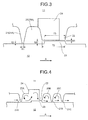
- FIG. 3 is a diagram schematically illustrating a relation between a vertical wall portion and a protrusion portion in the seal device of the first embodiment
- FIG. 4 is a cross-sectional view illustrating a working of the seal device of the first embodiment
- FIG. 5 is a graph illustrating a circumferential speed relative to an axial position of the seal device.
- a seal device 10 is provided between a stationary body 11 and a rotational body 12 to suppress a flow (leakage) of a fluid which flows between the stationary body 11 and the rotational body 12 in an axial center direction A and a circumferential direction B of the rotational body 12.
- the seal device 10 has a labyrinth seal structure as a basic structure to improve sealing performance by effectively applying a swirl breaker (swirling prevention) structure.
- the seal device 10 includes a plurality of first vertical wall portions 21 and a second vertical wall portion 22 which are provided in the stationary body 11, a protrusion portion 23 which is provided in the rotational body 12, and a plurality of swirl breaker chambers 24 which are provided in the stationary body 11.
- the first vertical wall portion 21 is formed in a ring shape which extends toward an outer periphery of the rotational body 12 from an inner periphery of the stationary body 11, the thickness thereof gradually becomes thinner from the stationary body 11 toward the rotational body 12, and a predetermined clearance is secured between a tip end of the first vertical wall portion and the outer periphery of the rotational body 12 in a radial direction.
- the plurality of first vertical wall portions 21, for example, three first vertical wall portions 21 (21A, 21B, and 21C) in the first embodiment are arranged along the axial center direction A, which is a flow direction of the fluid, at predetermined intervals.
- the second vertical wall portion 22 is formed in a ring shape which extends toward the outer periphery of the rotational body 12 from the inner periphery of the stationary body 11 and the thickness thereof gradually becomes thinner from the stationary body 11 toward the rotational body 12.
- the second vertical wall portion 22 is adjacent to three first vertical wall portions 21 (21A, 21B, and 21C) arranged along the axial center direction A which is the flow direction of the fluid and is arranged therebetween, that is, between the downstream side from the first vertical wall portion 21A of the uppermost upstream side and the upstream side from the first vertical wall portion 21B of the second stage in the flow direction of the fluid (axial center direction A). Then, the thickness of the tip end of the second vertical wall portion 22 is set to be thicker than that of the tip end of the first vertical wall portion 21 in the axial center direction A.
- the protrusion portion 23 is formed in a ring shape which faces the second vertical wall portion 22 and protrudes toward the inner periphery of the stationary body 11 from the outer periphery of the rotational body 12, and a predetermined clearance is secured between the tip end (outer periphery) of the protrusion portion 23 and the inner periphery of the stationary body 11, specifically the tip end (inner periphery) of the second vertical wall portion 22 in a radial direction.
- the length in the radial direction of the second vertical wall portion 22 is set to be shorter than the length in the radial direction of the first vertical wall portion 21, and the protrusion portion 23 is arranged so as to face the second vertical wall portion 22.
- the plurality of swirl breaker chambers 24 are chambers which are formed in the stationary body 11 at predetermined intervals in the circumferential direction B of the rotational body 12 to face the protrusion portion 23.
- the swirl breaker chamber 24 is formed in a substantially cubic shape, which is opened toward the protrusion portion 23 of the rotational body 12 and is also opened toward the first vertical wall portion 21A of the uppermost upstream side in the flow direction of the fluid (axial center direction A).
- spaces 25 (25A, 25B, and 25C) having substantially the same shape are formed between the first vertical wall portion 21A and the second vertical wall portion 22, between the second vertical wall portion 22 and the first vertical wall portion 21B, and between the first vertical wall portion 21B and the first vertical wall portion 21C, respectively. That is, the distance between a rear end of the first vertical wall portion 21A and a front end of the second vertical wall portion 22, the distance between a rear end of the second vertical wall portion 22 and a front end of the first vertical wall portion 21B, and the distance between a rear end of the first vertical wall portion 21B and a front end of the first vertical wall portion 21C are substantially the same.
- the swirl breaker chamber 24 of the stationary body 11 side faces the protrusion portion 23 of the rotational body 12 side in the radial direction, but is arranged away from the first vertical wall portion 21A side of the uppermost upstream side in the flow direction of the fluid (axial center direction A) so as to be opened to the space 25A.
- the thickness T2 of the tip end in the second vertical wall portion 22 is set to be thicker than the thickness T1 of the tip end in the first vertical wall portion 21 (T1 ⁇ T2).
- the thickness T3 of the protrusion portion 23 is set to be equal to or thinner than the thickness T2 of the tip end in the second vertical wall portion 22 (T3 ⁇ T2).
- the length S2 in the radial direction of the protrusion portion 23 is set to be not less than the clearance S1 between the tip end of the first vertical wall portion 21 and the rotational body 12 in the radial direction.
- the length S2 in the radial direction of the protrusion portion 23 be set to be more than twice the clearance S1 between the tip end of the first vertical wall portion 21 and the rotational body 12 in the radial direction.
- the swirl breaker chambers 24 are formed in the stationary body 11 at equal intervals in the circumferential direction B of the rotational body 12, and a length (width) W1 thereof in the circumferential direction is set to be substantially equal to a distance (clearance) W2 between the swirl breaker chambers 24.
- the fluid flowing between the stationary body 11 and the rotational body 12 has an axial center direction component along the axial center direction A of the rotational body 12 and a swirling direction component along the circumferential direction B.
- the fluid reaches the space 25A through the clearance S1 between the tip end of the first vertical wall portion 21A in the stationary body 11 and the outer periphery of the rotational body 12.
- the fluid collides with an upstream-side end face of the protrusion portion 23 in the rotational body 12 to flow to the outside of the rotational body 12, thereby some become a swirling flow within the space 25A, while the others enter into the swirl breaker chamber 24.
- the axial center direction component of the fluid along the axial center direction A of the rotational body 12 is attenuated by a collision with a wall surface of a front (downstream side in the axial center direction A) and the swirling direction component of the fluid along the circumferential direction B is attenuated by a collision with a side wall surface.
- the fluid flows through the clearance S3 between the tip end of the second vertical wall portion 22 in the stationary body 11 and the outer periphery of the protrusion portion 23 of the rotational body 12 to the space 25B from the swirl breaker chamber 24.
- the fluid is sealed by the first vertical wall portions 21A, 21B, and 21C and the second vertical wall portion 22, which function as a labyrinth seal, and is reduced in flow rate.
- the graph illustrated in FIG. 5 represents the circumferential speed relative to each position in the axial direction of the seal device 10.
- the circumferential speed of the fluid is reduced at the position of each seal fin, but is not sufficiently reduced as a result.
- an exciting force acts on the rotational body, and thus an unstable vibration occurs in the rotational body.
- the seal device 10 of the first embodiment represented by a solid line
- the first vertical wall portion 21A, the swirl breaker chamber 24, the second vertical wall portion 22, the first vertical wall portion 21B, and the first vertical wall portion 21C are located at positions L1 to L5, and the circumferential speed of the fluid is reduced at each of the positions L1 to L5.
- the circumferential speed of the fluid is significantly reduced by the swirl breaker chamber 24 from the position L1 to just before the position L3.
- the seal device 10 of the first embodiment can significantly reduce stiffness coefficient which is a cause of the unstable vibration.
- the seal device of the first embodiment is provided with three ring-shaped first vertical wall portions 21 (21A, 21B, and 21C) which extend toward the rotational body 12 from the stationary body 11 and are arranged in the axial center direction A of the rotational body 12 at predetermined intervals; the ring-shaped second vertical wall portion 22 which extends toward the rotational body 12 from the stationary body 11 and is adjacent to the first vertical wall portions 21, the thickness of which is thicker than the first vertical wall portions 21; the ring-shaped protrusion portion 23 which faces the second vertical wall portion 22 and protrudes toward the stationary body 11 from the rotational body 12; and the plurality of swirl breaker chambers 24 which are arranged in the stationary body 11 at predetermined intervals in the circumferential direction B of the rotational body 12 so as to face the protrusion portion 23.
- the fluid flowing therebetween flows to the downstream side through the clearance between the first vertical wall portion 21A and the rotational body 12 and is guided by the collision with the protrusion portion 23 to flow to an outer side in the radial direction and thus enter into the swirl breaker chamber 24.
- the axial center direction component and the swirling direction component of the fluid are attenuated by an inner wall of the swirl breaker chamber 24, and thus the fluid speed is reduced.
- the swirl breaker chamber 24 is provided at the downstream side from the first vertical wall portion 21A of the uppermost upstream side in the flow direction of the fluid which flows between the stationary body 11 and the rotational body 12 in the axial center direction A of the rotational body 12. Accordingly, the fluid passing through the clearance between the first vertical wall portion 21A and the rotational body 12 can appropriately flow to the swirl breaker chamber 24 by the protrusion portion 23 to attenuate the axial center direction component and the swirling direction component of the fluid.
- the swirl breaker chamber 24 is opened toward the protrusion portion 23 and is opened toward the first vertical wall portion 21A of the uppermost upstream side at the same time. Accordingly, the fluid, which passes through the clearance between the first vertical wall portion 21A and the rotational body 12 and is guided by the protrusion portion 23, can appropriately flow to the swirl breaker chamber 24 from the opening.
- the length in the radial direction of the protrusion portion 23 is set to be not less than the clearance between the tip end of the first vertical wall portion 21 and the rotational body 12 in the radial direction. Accordingly, the fluid, which passes through the clearance between the first vertical wall portion 21A and the rotational body 12, can be appropriately guided to the protrusion portion 23 to flow to the swirl breaker chamber 24 by the protrusion portion 23.
- the length in the circumferential direction of the swirl breaker chamber 24 is set to be substantially equal to the distance between the swirl breaker chambers 24. Accordingly, it is possible to appropriately attenuate the swirling direction component of the fluid entering into the swirl breaker chamber 24 and to reduce the speed by defining the length and clearance in the circumferential direction of the swirl breaker chamber 24.
- FIG. 6 is a cross-sectional view illustrating a seal device according to a second embodiment of the invention. Further, the members having the same function as in the first embodiment will be denoted by the same reference numerals and the detailed description thereof will not be provided.
- a seal device 30 is provided between a stationary body 11 and a rotational body 12 to suppress a flow (leakage) of a fluid which flows between the stationary body 11 and the rotational body 12 in the axial center direction A and the circumferential direction B (see FIG. 1 ) of the rotational body 12.
- the seal device 30 has a labyrinth seal structure as a basic structure to improve the sealing performance by effectively applying the swirl breaker structure.
- the seal device 30 includes a plurality of first vertical wall portions 31 and a second vertical wall portion 32 which are provided in the rotational body 12, a protrusion portion 33 which is provided in the rotational body 12, and a plurality of swirl breaker chambers 34 which are provided in the stationary body 11.
- the first vertical wall portion 31 is formed in a ring shape which extends toward an inner periphery of the stationary body 11 from an outer periphery of the rotational body 12, the thickness thereof gradually becomes thinner from the rotational body 12 toward the stationary body 11, and a predetermined clearance is secured between a tip end of the first vertical wall portion and the inner periphery of the stationary body 11.
- the plurality of first vertical wall portions 31, for example, three first vertical wall portions 31 (31A, 31B, and 31C) in the second embodiment are arranged along the axial center direction A, which is a flow direction of the fluid, at predetermined intervals.
- the second vertical wall portion 32 is formed in a ring shape which extends toward the inner periphery of the stationary body 11 from the outer periphery of the rotational body 12 and the thickness thereof gradually becomes thinner from the rotational body 12 toward the stationary body 11.
- the second vertical wall portion 32 is adjacent to three first vertical wall portions 31 (31A, 31B, and 31C) arranged along the axial center direction A which is the flow direction of the fluid and is arranged therebetween, that is, between the downstream side from the first vertical wall portion 31A of the uppermost upstream side and the upstream side from the first vertical wall portion 31B of the second stage in the flow direction of the fluid (axial center direction A). Then, the thickness of the tip end of the second vertical wall portion 32 is set to be thicker than that of the tip end of the first vertical wall portion 31 in the axial center direction A.
- the protrusion portion 33 is provided integrally with the tip end of the second vertical wall portion 32 to correspond to the second vertical wall portion 32 and is formed in the ring shape which protrudes toward the inner periphery of the stationary body 11 from the tip end of the second vertical wall portion 32.
- the plurality of swirl breaker chambers 34 are chambers which are formed in the stationary body 11 at predetermined intervals in the circumferential direction B of the rotational body 12 to face the protrusion portion 33 (second vertical wall portion 32).
- the swirl breaker chamber 34 is formed in a substantially cubic shape, which is opened toward the protrusion portion 33 of the rotational body 12.
- the stationary body 11 is provided with a recessed portion 36, which faces the protrusion portion 33 (second vertical wall portion 32) and is formed in a ring shape in the inner periphery of the stationary body, and the protrusion portion 33 of the tip end of the second vertical wall portion 32 is entered into the recessed portion 36. Then, a predetermined interval is secured between the tip end (outer periphery) of the second vertical wall portion 32 (protrusion portion 33) and the inner periphery of the stationary body 11.
- the length in the radial direction of the second vertical wall portion 32 and the protrusion portion 33 is set to be longer than that of the first vertical wall portion 31.
- spaces 35 (35A, 35B, and 35C) having substantially the same shape are formed between the first vertical wall portion 31A and the second vertical wall portion 32, between the second vertical wall portion 32 and the first vertical wall portion 31B, and between the first vertical wall portion 31B and the first vertical wall portion 31C, respectively. That is, the distance between a rear end of the first vertical wall portion 31A and a front end of the second vertical wall portion 32, the distance between a rear end of the second vertical wall portion 32 and a front end of the first vertical wall portion 31B, and the distance between a rear end of the first vertical wall portion 31B and a front end of the first vertical wall portion 31C are substantially the same.
- the length in the axial center direction A of the recessed portion 36 of the stationary body 11 is longer than that of the protrusion portion 33 (second vertical wall portion 32) of the rotational body 12, and the front end of the recessed portion 36 is communicated with the space 35A and the rear end thereof is communicated with the space 35B.
- the swirl breaker chamber 34 of the stationary body 11 side faces the protrusion portion 33 of the rotational body 12 side in the radial direction, but is arranged away from the first vertical wall portion 31A side of the uppermost upstream side in the flow direction of the fluid (axial center direction A) so as to be opened to the space 35A.
- the thickness of the tip end in the second vertical wall portion 32 is set to be thicker than the thickness of the tip end in the first vertical wall portion 31. Further, the length (clearance) between the tip end of the first vertical wall portion 31 and the stationary body 11 and the clearance between the tip end of the second vertical wall portion 32 (protrusion portion 33) and the recessed portion 36 have substantially the same length.
- the fluid flowing between the stationary body 11 and the rotational body 12 reaches the space 35A through the clearance between the tip end of the first vertical wall portion 31A in the rotational body 12 and the inner periphery of the stationary body 11.
- the fluid collides with an upstream-side end face of the second vertical wall portion 32 and the protrusion portion 33 in the rotational body 12 to flow to the outside of the rotational body 12, thereby some become a swirling flow within the space 35A, while the others enter into the swirl breaker chamber 34.
- the axial center direction component of the fluid along the axial center direction A of the rotational body 12 is attenuated by a collision with a wall surface of a front (downstream side in the axial center direction A) and the swirling direction component of the fluid along the circumferential direction B is attenuated by a collision with a side wall surface. Then, the fluid flows through the clearance between the tip end of the protrusion portion 33 in the rotational body 12 and the inner periphery of the recessed portion 36 of the stationary body 11 to the space 35B from the swirl breaker chamber 34.
- the fluid is sealed by the first vertical wall portions 31A, 31B, and 31C and the second vertical wall portion 32, which function as a labyrinth seal, and the protrusion portion 33 and is reduced in flow rate.
- the seal device of the second embodiment is provided with three ring-shaped first vertical wall portions 31 (31A, 31B, and 31C) which extend toward the stationary body 11 from the rotational body 12 and are arranged in the axial center direction A of the rotational body 12 at predetermined intervals; the ring-shaped second vertical wall portion 32 which extends toward the stationary body 11 from the rotational body 12 and is adjacent to the first vertical wall portions 31, the thickness of which is thicker than the first vertical wall portions 31; the ring-shaped protrusion portion 33 which protrudes toward the stationary body 11 in the tip portion of the second vertical wall portion 32; and the plurality of swirl breaker chambers 34 which are arranged in the stationary body 11 at predetermined intervals in the circumferential direction B of the rotational body 12 so as to face the protrusion portion 33.
- the fluid flowing therebetween flows to the downstream side through the clearance between the first vertical wall portion 31A and the stationary body 11 and is guided by the collision with the protrusion portion 33 to flow to an outer side in the radial direction and thus enter into the swirl breaker chamber 34.
- the axial center direction component and the swirling direction component of the fluid are attenuated by an inner wall of the swirl breaker chamber 34, and thus the fluid speed is reduced.
- the second vertical wall portions 22 and 32, the protrusion portions 23 and 33, and the swirl breaker chambers 24 and 34 are arranged between the downstream side from the first vertical wall portions 21A and 31A of the uppermost upstream side and the upstream side from the first vertical wall portions 21B and 31B of the second stage in the axial center direction A which is the flow direction of the fluid, but the positions thereof are not limited thereto.
- the second vertical wall portions 22 and 32, the protrusion portions 23 and 33, and the swirl breaker chambers 24 and 34 may be arranged anywhere at the downstream side from the first vertical wall portions 21A, 21B, 21C, 31A, 31B, and 31C, unless being arranged at the upstream side from the first vertical wall portions 21A and 31A of the uppermost upstream side in the axial center direction A which is the flow direction of the fluid.
- each embodiment described above is provided with three first vertical wall portions 21A, 21B, and 21C or 31A, 31B, and 31C, one second vertical wall portion 22 or 32, one protrusion portion 23 or 33, and one swirl breaker chamber 24 or 34, but the number thereof is not limited thereto.
- Two or four or more first vertical wall portions, two or more second vertical wall portions, two or more protrusion portions, and two or more swirl breaker chambers may be provided.
- two or more second vertical wall portions, two or more protrusion portions, and two or more swirl breaker chambers may be provided in a continuous state or be provided between the plurality of first vertical wall portions.
- the swirl breaker chambers 24 and 34 are formed in the cubic shape, but are not limited thereto and may be formed in a cuboid shape or may be formed in, for example, a hollow cylindrical shape or a hollow polygonal shape which is long in the radial direction of the rotational body 12.
- first vertical wall portions 21A, 21B, and 21C or 32A, 31B, and 31C and the second vertical wall portion 22 or 32 are provided in one of the stationary body 11 and the rotational body 12, but may be provided in both of them. That is, the configuration of the labyrinth seal is not limited to each embodiment.
- each embodiment described above is configured such that the first vertical wall portions 21A, 21B, and 21C or 32A, 31B, and 31C, the second vertical wall portion 22 or 32, the protrusion portion 23 or 33, and the swirl breaker chamber 24 or 34 are directly provided in the stationary body 11 or the rotational body 12, but may be configured in such a manner that one or two or more seal members, which are provided with the first vertical wall portion, the second vertical wall portion, the protrusion portion, and the swirl breaker chamber and are formed separately from the stationary body or the rotational body, are fixed to the stationary body or the rotational body.
Landscapes
- Engineering & Computer Science (AREA)
- General Engineering & Computer Science (AREA)
- Mechanical Engineering (AREA)
- Sealing Using Fluids, Sealing Without Contact, And Removal Of Oil (AREA)
- Turbine Rotor Nozzle Sealing (AREA)
Abstract
Description
- The present invention relates to a seal device which prevents leakage of a fluid between a stationary side and a rotational side.
- In a fluid machine adapted to rotatably support a rotational body in a housing, a seal device is provided between the housing and the rotational body in order to prevent an axial leakage flow of the fluid between the housing and the rotational body. Moreover, a labyrinth seal is generally applied as the seal device. The labyrinth seal is configured in such a manner that a plurality of seal fins are provided in at least one side of a stationary side such as the housing or a rotational body side to generate pressure loss by a clearance formed between the seal fin and the stationary side or the rotational body side and can suppress the axial leakage flow of the fluid by the pressure loss, thus performing a seal function.
- In the labyrinth seal, however, a swirling flow of the fluid occurs in the seal portion by a rotational motion of the rotational body to generate an exciting force in the seal portion, and thus there is a problem in that the rotational body is unstably vibrated by the exciting force. In order to solve this problem, for example, techniques disclosed in the following Patent Literatures have been proposed.
-
- Patent Literature 1: Japanese Patent Application Laid-open No.
58-143104 - Patent Literature 2: Japanese Patent Application Laid-open No.
59-000505 - Patent Literature 3: Japanese Patent Application Laid-open No.
2008-128275 - In the above Patent Literatures, a plate is provided in a seal fin to suppress a swirling flow. However, it is difficult to effectively suppress the swirling flow, which occurs in a seal portion, only by providing the swirling flow suppressing plate in the seal fin.
- The invention is intended to solve the above-described problem and to provide a seal device which can suppress a flow between a stationary body and a rotational body to suppress an unstable vibration of the rotational body and improve sealing performance.
- According to an aspect of the present invention, a seal device which is provided between a stationary body and a rotational body to suppress a flow of a fluid includes: a plurality of ring-shaped first vertical wall portions which extend from any one of the stationary body and the rotational body to the other side and are arranged at predetermined intervals in an axial center direction of the rotational body; a ring-shaped second vertical wall portion which extends from any one of the stationary body and the rotational body to the other side as in the first vertical wall portions and is adjacent to the first vertical wall portions, the thickness of which is thicker than the first vertical wall portions in the axial center direction of the rotational body; a ring-shaped protrusion portion which corresponds to the second vertical wall portion and protrudes toward the stationary body from the rotational body; and a plurality of swirl breaker chambers which are arranged in the stationary body at predetermined intervals in a circumferential direction of the rotational body to face the protrusion portion.
- Therefore, when the rotational body rotates with respect to the stationary body, the fluid flowing therebetween flows to the protrusion portion through the clearance between the first vertical wall portion and the stationary body or the rotational body and is guided to the protrusion portion to flow to an outer side in the radial direction and thus enter into the swirl breaker chamber; the axial center direction component and the swirling direction component of the fluid are attenuated by the swirl breaker chamber, and thus the fluid speed is reduced; and the flow between the stationary body and the rotational body can be suppressed, thereby it is possible to suppress the unstable vibration of the rotational body and improve the sealing performance.
- Advantageously, in the seal device, the swirl breaker chamber is provided at a downstream side from the first vertical wall portion of the uppermost stream side in a flow direction of the fluid flowing between the stationary body and the rotational body in the axial center direction of the rotational body.
- Accordingly, since the swirl breaker chamber is provided at the downstream side from the first vertical wall portion, the fluid passing through the clearance between the first vertical wall portion and the stationary body or the rotational body appropriately flows to the swirl breaker chamber by the protrusion portion, thereby it is possible to attenuate the axial center direction component and the swirling direction component.
- Advantageously, in the seal device, the swirl breaker chamber is opened toward the protrusion portion and is also opened toward the first vertical wall portion of the uppermost stream side.
- Therefore, since the swirl breaker chamber is opened to the upstream side in the flow direction of the fluid, the fluid guided outward by the protrusion portion can appropriately flow to the swirl breaker chamber.
- Advantageously, in the seal device, a length in a radial direction of the protrusion portion is set to be not less than a clearance between a tip end of the first vertical wall portion and the stationary body or the rotational body in the radial direction.
- Accordingly, since the length in the radial direction of the protrusion portion is defined, the fluid passing through the clearance between the first vertical wall portion and the stationary body or the rotational body is appropriately guided to the protrusion portion, and thus the fluid can flow to the swirl breaker chamber by the protrusion portion.
- Advantageously, in the seal device, a length in a circumferential direction of the swirl breaker chamber is set to be substantially equal to a distance between the swirl breaker chambers in the circumferential direction.
- Accordingly, since the length and clearance in the circumferential direction of the swirl breaker chamber are defined, it is possible to appropriately attenuate the swirling direction component of the fluid entering into the swirl breaker chamber.
- Advantageously, in the seal device, the first vertical wall portion and the second vertical wall portion are provided in the stationary body side, the second vertical wall portion is set to be shorter than the first vertical wall portion in the radial direction, and the protrusion portion is arranged so as to face the second vertical wall portion.
- Therefore, it is possible to simplify the configuration of the rotational body side.
- Advantageously, in the seal device, the first vertical wall portion and the second vertical wall portion are provided in the rotational body side, and the protrusion portion is provided at a tip end of the second vertical wall portion so that the second vertical wall portion is set to be longer than the first vertical wall portion in the radial direction.
- Accordingly, it is possible to simplify the configuration of the stationary body side.
- According to the seal device of the invention, since the seal device is provided with the plurality of ring-shaped first vertical wall portions, the ring-shaped second vertical wall portion which is adjacent to the first vertical wall portions and is thicker than the first vertical wall portion in the axial center direction, the ring-shaped protrusion portion which corresponds to the second vertical wall portion and protrudes from the rotational body, and the plurality of swirl breaker chambers which are arranged in the stationary body at predetermined intervals in the circumferential direction so as to face the protrusion portion, the leakage flow between the stationary body and the rotational body is suppressed in the axial center direction and the swirling direction, thereby it is possible to suppress the unstable vibration of the rotational body and thus improve the sealing performance.
-
-
FIG. 1 is a schematic view of a seal device according to a first embodiment of the invention. -
FIG. 2 is a cross-sectional view illustrating the seal device of the first embodiment. -
FIG. 3 is a diagram schematically illustrating a relation between a vertical wall portion and a protrusion portion in the seal device of the first embodiment. -
FIG. 4 is a cross-sectional view illustrating a working of the seal device of the first embodiment. -
FIG. 5 is a graph illustrating a circumferential speed relative to an axial position of the seal device. -
FIG. 6 is a cross-sectional view illustrating a seal device according to a second embodiment of the invention. Description of Embodiments - Hereinafter, preferred embodiments of a seal device according to the invention will be described in detail with reference to the accompanied drawings. Further, the invention is not limited to these embodiments, but may be intended to include the combination of each embodiment when numerous embodiments are present.
-
FIG. 1 is a schematic view of a seal device according to a first embodiment of the invention;FIG. 2 is a cross-sectional view illustrating the seal device of the first embodiment;FIG. 3 is a diagram schematically illustrating a relation between a vertical wall portion and a protrusion portion in the seal device of the first embodiment;FIG. 4 is a cross-sectional view illustrating a working of the seal device of the first embodiment; andFIG. 5 is a graph illustrating a circumferential speed relative to an axial position of the seal device. - In the first embodiment, as illustrated in
FIGS. 1 and 2 , aseal device 10 is provided between astationary body 11 and arotational body 12 to suppress a flow (leakage) of a fluid which flows between thestationary body 11 and therotational body 12 in an axial center direction A and a circumferential direction B of therotational body 12. Theseal device 10 has a labyrinth seal structure as a basic structure to improve sealing performance by effectively applying a swirl breaker (swirling prevention) structure. - That is, the
seal device 10 includes a plurality of firstvertical wall portions 21 and a secondvertical wall portion 22 which are provided in thestationary body 11, aprotrusion portion 23 which is provided in therotational body 12, and a plurality ofswirl breaker chambers 24 which are provided in thestationary body 11. - The first
vertical wall portion 21 is formed in a ring shape which extends toward an outer periphery of therotational body 12 from an inner periphery of thestationary body 11, the thickness thereof gradually becomes thinner from thestationary body 11 toward therotational body 12, and a predetermined clearance is secured between a tip end of the first vertical wall portion and the outer periphery of therotational body 12 in a radial direction. The plurality of firstvertical wall portions 21, for example, three first vertical wall portions 21 (21A, 21B, and 21C) in the first embodiment are arranged along the axial center direction A, which is a flow direction of the fluid, at predetermined intervals. - The second
vertical wall portion 22 is formed in a ring shape which extends toward the outer periphery of therotational body 12 from the inner periphery of thestationary body 11 and the thickness thereof gradually becomes thinner from thestationary body 11 toward therotational body 12. The secondvertical wall portion 22 is adjacent to three first vertical wall portions 21 (21A, 21B, and 21C) arranged along the axial center direction A which is the flow direction of the fluid and is arranged therebetween, that is, between the downstream side from the firstvertical wall portion 21A of the uppermost upstream side and the upstream side from the firstvertical wall portion 21B of the second stage in the flow direction of the fluid (axial center direction A). Then, the thickness of the tip end of the secondvertical wall portion 22 is set to be thicker than that of the tip end of the firstvertical wall portion 21 in the axial center direction A. - The
protrusion portion 23 is formed in a ring shape which faces the secondvertical wall portion 22 and protrudes toward the inner periphery of thestationary body 11 from the outer periphery of therotational body 12, and a predetermined clearance is secured between the tip end (outer periphery) of theprotrusion portion 23 and the inner periphery of thestationary body 11, specifically the tip end (inner periphery) of the secondvertical wall portion 22 in a radial direction. For this reason, the length in the radial direction of the secondvertical wall portion 22 is set to be shorter than the length in the radial direction of the firstvertical wall portion 21, and theprotrusion portion 23 is arranged so as to face the secondvertical wall portion 22. - The plurality of
swirl breaker chambers 24 are chambers which are formed in thestationary body 11 at predetermined intervals in the circumferential direction B of therotational body 12 to face theprotrusion portion 23. Theswirl breaker chamber 24 is formed in a substantially cubic shape, which is opened toward theprotrusion portion 23 of therotational body 12 and is also opened toward the firstvertical wall portion 21A of the uppermost upstream side in the flow direction of the fluid (axial center direction A). - In this case, spaces 25 (25A, 25B, and 25C) having substantially the same shape are formed between the first
vertical wall portion 21A and the secondvertical wall portion 22, between the secondvertical wall portion 22 and the firstvertical wall portion 21B, and between the firstvertical wall portion 21B and the firstvertical wall portion 21C, respectively. That is, the distance between a rear end of the firstvertical wall portion 21A and a front end of the secondvertical wall portion 22, the distance between a rear end of the secondvertical wall portion 22 and a front end of the firstvertical wall portion 21B, and the distance between a rear end of the firstvertical wall portion 21B and a front end of the firstvertical wall portion 21C are substantially the same. - In addition, the
swirl breaker chamber 24 of thestationary body 11 side faces theprotrusion portion 23 of therotational body 12 side in the radial direction, but is arranged away from the firstvertical wall portion 21A side of the uppermost upstream side in the flow direction of the fluid (axial center direction A) so as to be opened to thespace 25A. - Then, as illustrated in
FIG. 3 , when the thickness of the tip end in the firstvertical wall portion 21 is T1 and the thickness of the tip end in the secondvertical wall portion 22 is T2, the thickness T2 of the tip end in the secondvertical wall portion 22 is set to be thicker than the thickness T1 of the tip end in the first vertical wall portion 21 (T1 < T2). In addition, when the thickness of theprotrusion portion 23 is T3, the thickness T3 of theprotrusion portion 23 is set to be equal to or thinner than the thickness T2 of the tip end in the second vertical wall portion 22 (T3 ≤ T2). - Further, when the clearance between the tip end of the first
vertical wall portion 21 and the outer periphery of therotational body 12 in the radial direction is S1 and the length in the radial direction of theprotrusion portion 23 is S2, the length S2 in the radial direction of theprotrusion portion 23 is set to be not less than the clearance S1 between the tip end of the firstvertical wall portion 21 and therotational body 12 in the radial direction. In this case, it is preferable that the length S2 in the radial direction of theprotrusion portion 23 be set to be more than twice the clearance S1 between the tip end of the firstvertical wall portion 21 and therotational body 12 in the radial direction. Further, the clearance S1 between the tip end of the firstvertical wall portion 21 and therotational body 12 in the radial direction and the clearance S3 between the tip end of the secondvertical wall portion 22 and theprotrusion portion 23 in the radial direction have substantially the same length (distance) (S1 = S3). - Further, as illustrated in
FIGS. 1 and 2 , theswirl breaker chambers 24 are formed in thestationary body 11 at equal intervals in the circumferential direction B of therotational body 12, and a length (width) W1 thereof in the circumferential direction is set to be substantially equal to a distance (clearance) W2 between theswirl breaker chambers 24. - Therefore, as illustrated in
FIG. 4 , in a state where therotational body 12 rotates with respect to thestationary body 11, the fluid flowing between thestationary body 11 and therotational body 12 has an axial center direction component along the axial center direction A of therotational body 12 and a swirling direction component along the circumferential direction B. The fluid reaches thespace 25A through the clearance S1 between the tip end of the firstvertical wall portion 21A in thestationary body 11 and the outer periphery of therotational body 12. Here, the fluid collides with an upstream-side end face of theprotrusion portion 23 in therotational body 12 to flow to the outside of therotational body 12, thereby some become a swirling flow within thespace 25A, while the others enter into theswirl breaker chamber 24. - Thus, in the
swirl breaker chamber 24, the axial center direction component of the fluid along the axial center direction A of therotational body 12 is attenuated by a collision with a wall surface of a front (downstream side in the axial center direction A) and the swirling direction component of the fluid along the circumferential direction B is attenuated by a collision with a side wall surface. Then, the fluid flows through the clearance S3 between the tip end of the secondvertical wall portion 22 in thestationary body 11 and the outer periphery of theprotrusion portion 23 of therotational body 12 to thespace 25B from theswirl breaker chamber 24. - In addition, the fluid is sealed by the first
vertical wall portions vertical wall portion 22, which function as a labyrinth seal, and is reduced in flow rate. - Changes in fluid speed due to the
seal device 10 of the present embodiment will be described below. The graph illustrated inFIG. 5 represents the circumferential speed relative to each position in the axial direction of theseal device 10. In a seal device having five conventional seal fins (corresponding to the vertical wall portion of the invention) represented by a dashed-dotted line, the circumferential speed of the fluid is reduced at the position of each seal fin, but is not sufficiently reduced as a result. Thus, since the circumferential speed (swirling direction component) of the fluid is not sufficiently reduced, an exciting force acts on the rotational body, and thus an unstable vibration occurs in the rotational body. - Meanwhile, in the
seal device 10 of the first embodiment represented by a solid line, the firstvertical wall portion 21A, theswirl breaker chamber 24, the secondvertical wall portion 22, the firstvertical wall portion 21B, and the firstvertical wall portion 21C are located at positions L1 to L5, and the circumferential speed of the fluid is reduced at each of the positions L1 to L5. Particularly, the circumferential speed of the fluid is significantly reduced by theswirl breaker chamber 24 from the position L1 to just before the position L3. Thus, since the circumferential speed of the fluid is sufficiently reduced, the exciting force acting on therotational body 12 is decreased, and thus the occurrence of the unstable vibration is suppressed. That is, theseal device 10 of the first embodiment can significantly reduce stiffness coefficient which is a cause of the unstable vibration. - As described above, the seal device of the first embodiment is provided with three ring-shaped first vertical wall portions 21 (21A, 21B, and 21C) which extend toward the
rotational body 12 from thestationary body 11 and are arranged in the axial center direction A of therotational body 12 at predetermined intervals; the ring-shaped secondvertical wall portion 22 which extends toward therotational body 12 from thestationary body 11 and is adjacent to the firstvertical wall portions 21, the thickness of which is thicker than the firstvertical wall portions 21; the ring-shapedprotrusion portion 23 which faces the secondvertical wall portion 22 and protrudes toward thestationary body 11 from therotational body 12; and the plurality ofswirl breaker chambers 24 which are arranged in thestationary body 11 at predetermined intervals in the circumferential direction B of therotational body 12 so as to face theprotrusion portion 23. - Therefore, when the
rotational body 12 rotates with respect to thestationary body 11, the fluid flowing therebetween flows to the downstream side through the clearance between the firstvertical wall portion 21A and therotational body 12 and is guided by the collision with theprotrusion portion 23 to flow to an outer side in the radial direction and thus enter into theswirl breaker chamber 24. In theswirl breaker chamber 24, the axial center direction component and the swirling direction component of the fluid are attenuated by an inner wall of theswirl breaker chamber 24, and thus the fluid speed is reduced. When the speed of the fluid flowing between thestationary body 11 and therotational body 12 is reduced, the leakage flow between thestationary body 11 and therotational body 12 can be suppressed and the swirling direction component is also attenuated, thereby it is possible to suppress the unstable vibration of therotational body 12 and improve the sealing performance. - Further, in the seal device of the first embodiment, the
swirl breaker chamber 24 is provided at the downstream side from the firstvertical wall portion 21A of the uppermost upstream side in the flow direction of the fluid which flows between thestationary body 11 and therotational body 12 in the axial center direction A of therotational body 12. Accordingly, the fluid passing through the clearance between the firstvertical wall portion 21A and therotational body 12 can appropriately flow to theswirl breaker chamber 24 by theprotrusion portion 23 to attenuate the axial center direction component and the swirling direction component of the fluid. - In the seal device of the first embodiment, further, the
swirl breaker chamber 24 is opened toward theprotrusion portion 23 and is opened toward the firstvertical wall portion 21A of the uppermost upstream side at the same time. Accordingly, the fluid, which passes through the clearance between the firstvertical wall portion 21A and therotational body 12 and is guided by theprotrusion portion 23, can appropriately flow to theswirl breaker chamber 24 from the opening. - In the seal device of the first embodiment, further, the length in the radial direction of the
protrusion portion 23 is set to be not less than the clearance between the tip end of the firstvertical wall portion 21 and therotational body 12 in the radial direction. Accordingly, the fluid, which passes through the clearance between the firstvertical wall portion 21A and therotational body 12, can be appropriately guided to theprotrusion portion 23 to flow to theswirl breaker chamber 24 by theprotrusion portion 23. - In the seal device of the first embodiment, further, the length in the circumferential direction of the
swirl breaker chamber 24 is set to be substantially equal to the distance between theswirl breaker chambers 24. Accordingly, it is possible to appropriately attenuate the swirling direction component of the fluid entering into theswirl breaker chamber 24 and to reduce the speed by defining the length and clearance in the circumferential direction of theswirl breaker chamber 24. -
FIG. 6 is a cross-sectional view illustrating a seal device according to a second embodiment of the invention. Further, the members having the same function as in the first embodiment will be denoted by the same reference numerals and the detailed description thereof will not be provided. - In the second embodiment, as illustrated in
FIG. 6 , aseal device 30 is provided between astationary body 11 and arotational body 12 to suppress a flow (leakage) of a fluid which flows between thestationary body 11 and therotational body 12 in the axial center direction A and the circumferential direction B (seeFIG. 1 ) of therotational body 12. Theseal device 30 has a labyrinth seal structure as a basic structure to improve the sealing performance by effectively applying the swirl breaker structure. - That is, the
seal device 30 includes a plurality of first vertical wall portions 31 and a secondvertical wall portion 32 which are provided in therotational body 12, aprotrusion portion 33 which is provided in therotational body 12, and a plurality ofswirl breaker chambers 34 which are provided in thestationary body 11. - The first vertical wall portion 31 is formed in a ring shape which extends toward an inner periphery of the
stationary body 11 from an outer periphery of therotational body 12, the thickness thereof gradually becomes thinner from therotational body 12 toward thestationary body 11, and a predetermined clearance is secured between a tip end of the first vertical wall portion and the inner periphery of thestationary body 11. The plurality of first vertical wall portions 31, for example, three first vertical wall portions 31 (31A, 31B, and 31C) in the second embodiment are arranged along the axial center direction A, which is a flow direction of the fluid, at predetermined intervals. - The second
vertical wall portion 32 is formed in a ring shape which extends toward the inner periphery of thestationary body 11 from the outer periphery of therotational body 12 and the thickness thereof gradually becomes thinner from therotational body 12 toward thestationary body 11. The secondvertical wall portion 32 is adjacent to three first vertical wall portions 31 (31A, 31B, and 31C) arranged along the axial center direction A which is the flow direction of the fluid and is arranged therebetween, that is, between the downstream side from the firstvertical wall portion 31A of the uppermost upstream side and the upstream side from the firstvertical wall portion 31B of the second stage in the flow direction of the fluid (axial center direction A). Then, the thickness of the tip end of the secondvertical wall portion 32 is set to be thicker than that of the tip end of the first vertical wall portion 31 in the axial center direction A. - The
protrusion portion 33 is provided integrally with the tip end of the secondvertical wall portion 32 to correspond to the secondvertical wall portion 32 and is formed in the ring shape which protrudes toward the inner periphery of thestationary body 11 from the tip end of the secondvertical wall portion 32. - The plurality of
swirl breaker chambers 34 are chambers which are formed in thestationary body 11 at predetermined intervals in the circumferential direction B of therotational body 12 to face the protrusion portion 33 (second vertical wall portion 32). Theswirl breaker chamber 34 is formed in a substantially cubic shape, which is opened toward theprotrusion portion 33 of therotational body 12. - In this case, the
stationary body 11 is provided with a recessedportion 36, which faces the protrusion portion 33 (second vertical wall portion 32) and is formed in a ring shape in the inner periphery of the stationary body, and theprotrusion portion 33 of the tip end of the secondvertical wall portion 32 is entered into the recessedportion 36. Then, a predetermined interval is secured between the tip end (outer periphery) of the second vertical wall portion 32 (protrusion portion 33) and the inner periphery of thestationary body 11. Thus, the length in the radial direction of the secondvertical wall portion 32 and theprotrusion portion 33 is set to be longer than that of the first vertical wall portion 31. - In addition, spaces 35 (35A, 35B, and 35C) having substantially the same shape are formed between the first
vertical wall portion 31A and the secondvertical wall portion 32, between the secondvertical wall portion 32 and the firstvertical wall portion 31B, and between the firstvertical wall portion 31B and the firstvertical wall portion 31C, respectively. That is, the distance between a rear end of the firstvertical wall portion 31A and a front end of the secondvertical wall portion 32, the distance between a rear end of the secondvertical wall portion 32 and a front end of the firstvertical wall portion 31B, and the distance between a rear end of the firstvertical wall portion 31B and a front end of the firstvertical wall portion 31C are substantially the same. Then, the length in the axial center direction A of the recessedportion 36 of thestationary body 11 is longer than that of the protrusion portion 33 (second vertical wall portion 32) of therotational body 12, and the front end of the recessedportion 36 is communicated with thespace 35A and the rear end thereof is communicated with thespace 35B. - In addition, the
swirl breaker chamber 34 of thestationary body 11 side faces theprotrusion portion 33 of therotational body 12 side in the radial direction, but is arranged away from the firstvertical wall portion 31A side of the uppermost upstream side in the flow direction of the fluid (axial center direction A) so as to be opened to thespace 35A. - Then, as in the first embodiment, the thickness of the tip end in the second
vertical wall portion 32 is set to be thicker than the thickness of the tip end in the first vertical wall portion 31. Further, the length (clearance) between the tip end of the first vertical wall portion 31 and thestationary body 11 and the clearance between the tip end of the second vertical wall portion 32 (protrusion portion 33) and the recessedportion 36 have substantially the same length. - Therefore, in a state where the
rotational body 12 rotates with respect to thestationary body 11, the fluid flowing between thestationary body 11 and therotational body 12 reaches thespace 35A through the clearance between the tip end of the firstvertical wall portion 31A in therotational body 12 and the inner periphery of thestationary body 11. Here, the fluid collides with an upstream-side end face of the secondvertical wall portion 32 and theprotrusion portion 33 in therotational body 12 to flow to the outside of therotational body 12, thereby some become a swirling flow within thespace 35A, while the others enter into theswirl breaker chamber 34. - Thus, in the
swirl breaker chamber 34, the axial center direction component of the fluid along the axial center direction A of therotational body 12 is attenuated by a collision with a wall surface of a front (downstream side in the axial center direction A) and the swirling direction component of the fluid along the circumferential direction B is attenuated by a collision with a side wall surface. Then, the fluid flows through the clearance between the tip end of theprotrusion portion 33 in therotational body 12 and the inner periphery of the recessedportion 36 of thestationary body 11 to thespace 35B from theswirl breaker chamber 34. - In addition, the fluid is sealed by the first
vertical wall portions vertical wall portion 32, which function as a labyrinth seal, and theprotrusion portion 33 and is reduced in flow rate. - As described above, the seal device of the second embodiment is provided with three ring-shaped first vertical wall portions 31 (31A, 31B, and 31C) which extend toward the
stationary body 11 from therotational body 12 and are arranged in the axial center direction A of therotational body 12 at predetermined intervals; the ring-shaped secondvertical wall portion 32 which extends toward thestationary body 11 from therotational body 12 and is adjacent to the first vertical wall portions 31, the thickness of which is thicker than the first vertical wall portions 31; the ring-shapedprotrusion portion 33 which protrudes toward thestationary body 11 in the tip portion of the secondvertical wall portion 32; and the plurality ofswirl breaker chambers 34 which are arranged in thestationary body 11 at predetermined intervals in the circumferential direction B of therotational body 12 so as to face theprotrusion portion 33. - Therefore, when the
rotational body 12 rotates with respect to thestationary body 11, the fluid flowing therebetween flows to the downstream side through the clearance between the firstvertical wall portion 31A and thestationary body 11 and is guided by the collision with theprotrusion portion 33 to flow to an outer side in the radial direction and thus enter into theswirl breaker chamber 34. In theswirl breaker chamber 34, the axial center direction component and the swirling direction component of the fluid are attenuated by an inner wall of theswirl breaker chamber 34, and thus the fluid speed is reduced. When the speed of the fluid flowing between thestationary body 11 and therotational body 12 is reduced, the leakage flow between thestationary body 11 and therotational body 12 can be suppressed and the swirling direction component is also attenuated, thereby it is possible to suppress the unstable vibration of therotational body 12 and improve the sealing performance. - Further, in each embodiment described above, the second
vertical wall portions protrusion portions swirl breaker chambers vertical wall portions vertical wall portions vertical wall portions protrusion portions swirl breaker chambers vertical wall portions vertical wall portions - Further, each embodiment described above is provided with three first
vertical wall portions vertical wall portion protrusion portion swirl breaker chamber - Further, in each embodiment described above, the
swirl breaker chambers rotational body 12. - Further, in each embodiment described above, the first
vertical wall portions vertical wall portion stationary body 11 and therotational body 12, but may be provided in both of them. That is, the configuration of the labyrinth seal is not limited to each embodiment. - Further, each embodiment described above is configured such that the first
vertical wall portions vertical wall portion protrusion portion swirl breaker chamber stationary body 11 or therotational body 12, but may be configured in such a manner that one or two or more seal members, which are provided with the first vertical wall portion, the second vertical wall portion, the protrusion portion, and the swirl breaker chamber and are formed separately from the stationary body or the rotational body, are fixed to the stationary body or the rotational body. -
- 10, 30
- SEAL DEVICE
- 11
- STATIONARY BODY
- 12
- ROTATIONAL BODY
- 21, 21A, 21B, 21C, 31, 31A, 31B, 31C
- FIRST VERTICAL WALL PORTION
- 22, 32
- SECOND VERTICAL WALL PORTION
- 23, 33
- PROTRUSION PORTION
- 24, 34
- SWIRL BREAKER CHAMBER
- 25, 25A, 25B, 25C, 35, 35A, 35B, 35C
- SPACE
- 36
- RECESSED PORTION
Claims (7)
- A seal device which is provided between a stationary body and a rotational body to suppress a flow of a fluid, the seal device comprising:a plurality of ring-shaped first vertical wall portions which extend from any one of the stationary body and the rotational body to the other side and are arranged at predetermined intervals in an axial center direction of the rotational body;a ring-shaped second vertical wall portion which extends from any one of the stationary body and the rotational body to the other side as in the first vertical wall portions and is adjacent to the first vertical wall portions, the thickness of which is thicker than the first vertical wall portions in the axial center direction of the rotational body;a ring-shaped protrusion portion which corresponds to the second vertical wall portion and protrudes toward the stationary body from the rotational body; anda plurality of swirl breaker chambers which are arranged in the stationary body at predetermined intervals in a circumferential direction of the rotational body to face the protrusion portion.
- The seal device according to claim 1, wherein the swirl breaker chamber is provided at a downstream side from the first vertical wall portion of the uppermost stream side in a flow direction of the fluid flowing between the stationary body and the rotational body in the axial center direction of the rotational body.
- The seal device according to claim 2, wherein the swirl breaker chamber is opened toward the protrusion portion and is also opened toward the first vertical wall portion of the uppermost stream side.
- The seal device according to any one of claims 1 to 3, wherein a length in a radial direction of the protrusion portion is set to be not less than a clearance between a tip end of the first vertical wall portion and the stationary body or the rotational body in the radial direction.
- The seal device according to any one of claims 1 to 4, wherein a length in a circumferential direction of the swirl breaker chamber is set to be substantially equal to a distance between the swirl breaker chambers in the circumferential direction.
- The seal device according to any one of claims 1 to 5, wherein the first vertical wall portion and the second vertical wall portion are provided in the stationary body side, the second vertical wall portion is set to be shorter than the first vertical wall portion in the radial direction, and the protrusion portion is arranged so as to face the second vertical wall portion.
- The seal device according to any one of claims 1 to 5, wherein the first vertical wall portion and the second vertical wall portion are provided in the rotational body side, and the protrusion portion is provided at a tip end of the second vertical wall portion so that the second vertical wall portion is set to be longer than the first vertical wall portion in the radial direction.
Applications Claiming Priority (2)
| Application Number | Priority Date | Filing Date | Title |
|---|---|---|---|
| JP2011232159A JP5774963B2 (en) | 2011-10-21 | 2011-10-21 | Sealing device |
| PCT/JP2012/075674 WO2013058112A1 (en) | 2011-10-21 | 2012-10-03 | Seal device |
Publications (2)
| Publication Number | Publication Date |
|---|---|
| EP2749797A1 true EP2749797A1 (en) | 2014-07-02 |
| EP2749797A4 EP2749797A4 (en) | 2015-08-19 |
Family
ID=48140764
Family Applications (1)
| Application Number | Title | Priority Date | Filing Date |
|---|---|---|---|
| EP12841052.9A Withdrawn EP2749797A4 (en) | 2011-10-21 | 2012-10-03 | Seal device |
Country Status (5)
| Country | Link |
|---|---|
| US (1) | US20140175754A1 (en) |
| EP (1) | EP2749797A4 (en) |
| JP (1) | JP5774963B2 (en) |
| CN (1) | CN103717951B (en) |
| WO (1) | WO2013058112A1 (en) |
Cited By (2)
| Publication number | Priority date | Publication date | Assignee | Title |
|---|---|---|---|---|
| EP2899405A4 (en) * | 2012-11-13 | 2015-10-21 | Mitsubishi Heavy Ind Compressor Corp | ROTARY MACHINE |
| RU242119U1 (en) * | 2025-08-25 | 2026-03-13 | Не публикуется в соответствии с постановлением Правительства РФ от 2 сентября 2024 г. N 1209. | Labyrinth seal |
Families Citing this family (5)
| Publication number | Priority date | Publication date | Assignee | Title |
|---|---|---|---|---|
| DE102009030559B4 (en) * | 2009-06-25 | 2012-11-22 | Federal-Mogul Sealing Systems Gmbh | Flat gasket with a full bead |
| WO2015187233A1 (en) * | 2014-06-02 | 2015-12-10 | Dresser-Rand Company | Stator can for improved rotordynamic stability |
| JP2017075621A (en) * | 2015-10-13 | 2017-04-20 | 株式会社日立製作所 | Annular seal structure and fluid machine including the same |
| JP6846374B2 (en) * | 2018-03-08 | 2021-03-24 | 三菱重工業株式会社 | Moving wing side sealing device, stationary wing side sealing device and rotating machine |
| CN114151142B (en) * | 2021-11-11 | 2023-09-01 | 中国联合重型燃气轮机技术有限公司 | Seal assembly and gas turbine |
Family Cites Families (24)
| Publication number | Priority date | Publication date | Assignee | Title |
|---|---|---|---|---|
| US1463018A (en) * | 1921-01-15 | 1923-07-24 | Gen Electric | Shaft bearing |
| DE2413655C3 (en) * | 1974-03-21 | 1978-05-03 | Maschinenfabrik Augsburg-Nuernberg Ag, 8500 Nuernberg | Device for dynamic stabilization of the rotor of a gas or steam turbine |
| JPS58143104A (en) * | 1982-02-19 | 1983-08-25 | Hitachi Ltd | Leakage preventive device of axial-flow hydraulic machine |
| JPS59505A (en) * | 1982-06-28 | 1984-01-05 | Toshiba Corp | Steam turbine |
| JPH05248548A (en) * | 1992-03-09 | 1993-09-24 | Hitachi Ltd | Labyrinth seal |
| JPH07139306A (en) * | 1993-11-17 | 1995-05-30 | Mitsubishi Heavy Ind Ltd | Labyrinth seal |
| US6155778A (en) * | 1998-12-30 | 2000-12-05 | General Electric Company | Recessed turbine shroud |
| WO2000047919A1 (en) * | 1999-02-09 | 2000-08-17 | General Electric Company | Combined labyrinth and brush seals for rotary machines |
| WO2004113769A2 (en) * | 2003-06-20 | 2004-12-29 | Elliott Company | Stepped labyrinth damper seal |
| US20060237914A1 (en) * | 2003-06-20 | 2006-10-26 | Elliott Company | Swirl-reversal abradable labyrinth seal |
| JP2005214144A (en) * | 2004-01-30 | 2005-08-11 | Toshiba Corp | Swirl flow prevention device for fluid machinery |
| EP1707856A1 (en) * | 2005-04-01 | 2006-10-04 | Cross Manufacturing Company (1938) Limited | Brush seals |
| US7641200B2 (en) * | 2005-11-28 | 2010-01-05 | General Electric Company | Variable clearance packing ring arrangement |
| US7731478B2 (en) * | 2006-05-25 | 2010-06-08 | General Electric Company | Method and apparatus for variable clearance packing |
| US20080080972A1 (en) * | 2006-09-29 | 2008-04-03 | General Electric Company | Stationary-rotating assemblies having surface features for enhanced containment of fluid flow, and related processes |
| JP5113369B2 (en) * | 2006-11-16 | 2013-01-09 | 株式会社日立製作所 | Labyrinth seal |
| US7819625B2 (en) * | 2007-05-07 | 2010-10-26 | Siemens Energy, Inc. | Abradable CMC stacked laminate ring segment for a gas turbine |
| JP4668976B2 (en) * | 2007-12-04 | 2011-04-13 | 株式会社日立製作所 | Steam turbine seal structure |
| EP2083200A1 (en) * | 2008-01-24 | 2009-07-29 | Siemens Aktiengesellschaft | Seal assembly |
| JP2010077882A (en) * | 2008-09-25 | 2010-04-08 | Toyota Motor Corp | Labyrinth seal structure for multistage turbine |
| EP2249066A1 (en) * | 2009-05-07 | 2010-11-10 | Siemens Aktiengesellschaft | Sealing apparatus and method for steam turbines |
| US20110309585A1 (en) * | 2009-06-16 | 2011-12-22 | Hidekazu Uehara | Shaft seal device |
| US8360712B2 (en) * | 2010-01-22 | 2013-01-29 | General Electric Company | Method and apparatus for labyrinth seal packing rings |
| US9200528B2 (en) * | 2012-09-11 | 2015-12-01 | General Electric Company | Swirl interruption seal teeth for seal assembly |
-
2011
- 2011-10-21 JP JP2011232159A patent/JP5774963B2/en not_active Expired - Fee Related
-
2012
- 2012-10-03 WO PCT/JP2012/075674 patent/WO2013058112A1/en not_active Ceased
- 2012-10-03 US US14/236,988 patent/US20140175754A1/en not_active Abandoned
- 2012-10-03 EP EP12841052.9A patent/EP2749797A4/en not_active Withdrawn
- 2012-10-03 CN CN201280038690.9A patent/CN103717951B/en not_active Expired - Fee Related
Cited By (3)
| Publication number | Priority date | Publication date | Assignee | Title |
|---|---|---|---|---|
| EP2899405A4 (en) * | 2012-11-13 | 2015-10-21 | Mitsubishi Heavy Ind Compressor Corp | ROTARY MACHINE |
| US10066750B2 (en) | 2012-11-13 | 2018-09-04 | Mitsubishi Heavy Industries Compressor Corporation | Rotary machine |
| RU242119U1 (en) * | 2025-08-25 | 2026-03-13 | Не публикуется в соответствии с постановлением Правительства РФ от 2 сентября 2024 г. N 1209. | Labyrinth seal |
Also Published As
| Publication number | Publication date |
|---|---|
| JP2013087935A (en) | 2013-05-13 |
| CN103717951A (en) | 2014-04-09 |
| JP5774963B2 (en) | 2015-09-09 |
| WO2013058112A1 (en) | 2013-04-25 |
| CN103717951B (en) | 2016-01-20 |
| EP2749797A4 (en) | 2015-08-19 |
| US20140175754A1 (en) | 2014-06-26 |
Similar Documents
| Publication | Publication Date | Title |
|---|---|---|
| US20140175754A1 (en) | Seal device | |
| CN105587346B (en) | Sealing device and turbomachinery | |
| EP2913566B1 (en) | Oil seal | |
| CN104813082B (en) | Seals and rotating machinery | |
| CN102959184B (en) | Turbine | |
| EP3279526B1 (en) | Sealing apparatus | |
| JP6135830B2 (en) | Sealing structure | |
| WO2014103446A1 (en) | Segmented seal | |
| JP2012102831A (en) | Labyrinth seal device and turbo machine using the same | |
| JP6628804B2 (en) | Damper | |
| US10550720B2 (en) | Guide vane segment | |
| US11702947B2 (en) | Rotating machine | |
| JP2010077882A (en) | Labyrinth seal structure for multistage turbine | |
| EP2700789A1 (en) | Turbine stator vane and gas turbine | |
| CN112771248B (en) | Turbine stator, steam turbine and partition plate | |
| JP6022006B2 (en) | Sealing device | |
| JP6088029B2 (en) | Sealing device | |
| JP6256030B2 (en) | Buffering | |
| JP2019011768A (en) | Seal device and turbo machine | |
| JP2006233857A (en) | Turbine bucket and turbine provided with it | |
| WO2017146136A1 (en) | Sealing device and rotating machine | |
| JP2015119595A (en) | Motor cooling structure | |
| JP2008002648A (en) | Seal ring | |
| JP2011122681A (en) | Oil seal | |
| JP2013204795A (en) | Seal device |
Legal Events
| Date | Code | Title | Description |
|---|---|---|---|
| PUAI | Public reference made under article 153(3) epc to a published international application that has entered the european phase |
Free format text: ORIGINAL CODE: 0009012 |
|
| 17P | Request for examination filed |
Effective date: 20140205 |
|
| AK | Designated contracting states |
Kind code of ref document: A1 Designated state(s): AL AT BE BG CH CY CZ DE DK EE ES FI FR GB GR HR HU IE IS IT LI LT LU LV MC MK MT NL NO PL PT RO RS SE SI SK SM TR |
|
| DAX | Request for extension of the european patent (deleted) | ||
| RA4 | Supplementary search report drawn up and despatched (corrected) |
Effective date: 20150721 |
|
| RIC1 | Information provided on ipc code assigned before grant |
Ipc: F01D 11/02 20060101ALI20150715BHEP Ipc: F16J 15/447 20060101AFI20150715BHEP Ipc: F01D 11/00 20060101ALI20150715BHEP |
|
| 17Q | First examination report despatched |
Effective date: 20171002 |
|
| STAA | Information on the status of an ep patent application or granted ep patent |
Free format text: STATUS: THE APPLICATION IS DEEMED TO BE WITHDRAWN |
|
| 18D | Application deemed to be withdrawn |
Effective date: 20180731 |