EP2749538A1 - Fresh water generation method - Google Patents
Fresh water generation method Download PDFInfo
- Publication number
- EP2749538A1 EP2749538A1 EP12826357.1A EP12826357A EP2749538A1 EP 2749538 A1 EP2749538 A1 EP 2749538A1 EP 12826357 A EP12826357 A EP 12826357A EP 2749538 A1 EP2749538 A1 EP 2749538A1
- Authority
- EP
- European Patent Office
- Prior art keywords
- branch line
- generation method
- water
- raw water
- fresh water
- Prior art date
- Legal status (The legal status is an assumption and is not a legal conclusion. Google has not performed a legal analysis and makes no representation as to the accuracy of the status listed.)
- Withdrawn
Links
- 238000000034 method Methods 0.000 title claims abstract description 53
- 239000013505 freshwater Substances 0.000 title claims abstract description 42
- XLYOFNOQVPJJNP-UHFFFAOYSA-N water Substances O XLYOFNOQVPJJNP-UHFFFAOYSA-N 0.000 claims abstract description 164
- 230000014759 maintenance of location Effects 0.000 claims abstract description 36
- 238000004062 sedimentation Methods 0.000 claims description 34
- 238000011282 treatment Methods 0.000 claims description 24
- 150000003839 salts Chemical class 0.000 claims description 15
- 238000000926 separation method Methods 0.000 claims description 10
- 239000013535 sea water Substances 0.000 description 27
- 239000000047 product Substances 0.000 description 19
- 238000010612 desalination reaction Methods 0.000 description 16
- 239000012528 membrane Substances 0.000 description 16
- 238000001223 reverse osmosis Methods 0.000 description 12
- 238000010586 diagram Methods 0.000 description 7
- 239000012141 concentrate Substances 0.000 description 5
- 239000005416 organic matter Substances 0.000 description 5
- 239000000701 coagulant Substances 0.000 description 3
- 239000007788 liquid Substances 0.000 description 3
- 230000003204 osmotic effect Effects 0.000 description 3
- 239000002351 wastewater Substances 0.000 description 3
- 238000010521 absorption reaction Methods 0.000 description 2
- 239000003463 adsorbent Substances 0.000 description 2
- QVGXLLKOCUKJST-UHFFFAOYSA-N atomic oxygen Chemical compound [O] QVGXLLKOCUKJST-UHFFFAOYSA-N 0.000 description 2
- 230000033228 biological regulation Effects 0.000 description 2
- 238000007599 discharging Methods 0.000 description 2
- 238000005516 engineering process Methods 0.000 description 2
- 230000007613 environmental effect Effects 0.000 description 2
- 230000005484 gravity Effects 0.000 description 2
- 239000003673 groundwater Substances 0.000 description 2
- 238000009434 installation Methods 0.000 description 2
- 229910052760 oxygen Inorganic materials 0.000 description 2
- 239000001301 oxygen Substances 0.000 description 2
- 230000003134 recirculating effect Effects 0.000 description 2
- 238000011084 recovery Methods 0.000 description 2
- 238000003756 stirring Methods 0.000 description 2
- OKTJSMMVPCPJKN-UHFFFAOYSA-N Carbon Chemical compound [C] OKTJSMMVPCPJKN-UHFFFAOYSA-N 0.000 description 1
- 241000337007 Oceania Species 0.000 description 1
- 230000004071 biological effect Effects 0.000 description 1
- 229910052799 carbon Inorganic materials 0.000 description 1
- 238000005345 coagulation Methods 0.000 description 1
- 230000015271 coagulation Effects 0.000 description 1
- 239000003651 drinking water Substances 0.000 description 1
- 235000020188 drinking water Nutrition 0.000 description 1
- 238000001704 evaporation Methods 0.000 description 1
- 239000004744 fabric Substances 0.000 description 1
- 238000001914 filtration Methods 0.000 description 1
- 239000007789 gas Substances 0.000 description 1
- 230000001788 irregular Effects 0.000 description 1
- 238000004949 mass spectrometry Methods 0.000 description 1
- 239000000463 material Substances 0.000 description 1
- 238000001471 micro-filtration Methods 0.000 description 1
- 238000012544 monitoring process Methods 0.000 description 1
- 238000001728 nano-filtration Methods 0.000 description 1
- 239000012466 permeate Substances 0.000 description 1
- 239000003208 petroleum Substances 0.000 description 1
- 238000012958 reprocessing Methods 0.000 description 1
- 238000009287 sand filtration Methods 0.000 description 1
- 239000010865 sewage Substances 0.000 description 1
- XZPVPNZTYPUODG-UHFFFAOYSA-M sodium;chloride;dihydrate Chemical compound O.O.[Na+].[Cl-] XZPVPNZTYPUODG-UHFFFAOYSA-M 0.000 description 1
- 239000007787 solid Substances 0.000 description 1
- 238000001179 sorption measurement Methods 0.000 description 1
- 239000000126 substance Substances 0.000 description 1
- 238000000108 ultra-filtration Methods 0.000 description 1
Images



Classifications
-
- B—PERFORMING OPERATIONS; TRANSPORTING
- B01—PHYSICAL OR CHEMICAL PROCESSES OR APPARATUS IN GENERAL
- B01D—SEPARATION
- B01D21/00—Separation of suspended solid particles from liquids by sedimentation
- B01D21/24—Feed or discharge mechanisms for settling tanks
- B01D21/2405—Feed mechanisms for settling tanks
- B01D21/2416—Liquid distributors with a plurality of feed points
-
- C—CHEMISTRY; METALLURGY
- C02—TREATMENT OF WATER, WASTE WATER, SEWAGE, OR SLUDGE
- C02F—TREATMENT OF WATER, WASTE WATER, SEWAGE, OR SLUDGE
- C02F1/00—Treatment of water, waste water, or sewage
- C02F1/006—Water distributors either inside a treatment tank or directing the water to several treatment tanks; Water treatment plants incorporating these distributors, with or without chemical or biological tanks
-
- B—PERFORMING OPERATIONS; TRANSPORTING
- B01—PHYSICAL OR CHEMICAL PROCESSES OR APPARATUS IN GENERAL
- B01D—SEPARATION
- B01D36/00—Filter circuits or combinations of filters with other separating devices
- B01D36/04—Combinations of filters with settling tanks
-
- B—PERFORMING OPERATIONS; TRANSPORTING
- B01—PHYSICAL OR CHEMICAL PROCESSES OR APPARATUS IN GENERAL
- B01D—SEPARATION
- B01D61/00—Processes of separation using semi-permeable membranes, e.g. dialysis, osmosis or ultrafiltration; Apparatus, accessories or auxiliary operations specially adapted therefor
- B01D61/02—Reverse osmosis; Hyperfiltration ; Nanofiltration
- B01D61/10—Accessories; Auxiliary operations
-
- C—CHEMISTRY; METALLURGY
- C02—TREATMENT OF WATER, WASTE WATER, SEWAGE, OR SLUDGE
- C02F—TREATMENT OF WATER, WASTE WATER, SEWAGE, OR SLUDGE
- C02F1/00—Treatment of water, waste water, or sewage
-
- C—CHEMISTRY; METALLURGY
- C02—TREATMENT OF WATER, WASTE WATER, SEWAGE, OR SLUDGE
- C02F—TREATMENT OF WATER, WASTE WATER, SEWAGE, OR SLUDGE
- C02F1/00—Treatment of water, waste water, or sewage
- C02F1/44—Treatment of water, waste water, or sewage by dialysis, osmosis or reverse osmosis
- C02F1/441—Treatment of water, waste water, or sewage by dialysis, osmosis or reverse osmosis by reverse osmosis
-
- B—PERFORMING OPERATIONS; TRANSPORTING
- B01—PHYSICAL OR CHEMICAL PROCESSES OR APPARATUS IN GENERAL
- B01D—SEPARATION
- B01D21/00—Separation of suspended solid particles from liquids by sedimentation
- B01D21/02—Settling tanks with single outlets for the separated liquid
-
- C—CHEMISTRY; METALLURGY
- C02—TREATMENT OF WATER, WASTE WATER, SEWAGE, OR SLUDGE
- C02F—TREATMENT OF WATER, WASTE WATER, SEWAGE, OR SLUDGE
- C02F2103/00—Nature of the water, waste water, sewage or sludge to be treated
- C02F2103/007—Contaminated open waterways, rivers, lakes or ponds
-
- C—CHEMISTRY; METALLURGY
- C02—TREATMENT OF WATER, WASTE WATER, SEWAGE, OR SLUDGE
- C02F—TREATMENT OF WATER, WASTE WATER, SEWAGE, OR SLUDGE
- C02F2209/00—Controlling or monitoring parameters in water treatment
- C02F2209/001—Upstream control, i.e. monitoring for predictive control
-
- C—CHEMISTRY; METALLURGY
- C02—TREATMENT OF WATER, WASTE WATER, SEWAGE, OR SLUDGE
- C02F—TREATMENT OF WATER, WASTE WATER, SEWAGE, OR SLUDGE
- C02F2209/00—Controlling or monitoring parameters in water treatment
- C02F2209/08—Chemical Oxygen Demand [COD]; Biological Oxygen Demand [BOD]
-
- C—CHEMISTRY; METALLURGY
- C02—TREATMENT OF WATER, WASTE WATER, SEWAGE, OR SLUDGE
- C02F—TREATMENT OF WATER, WASTE WATER, SEWAGE, OR SLUDGE
- C02F2209/00—Controlling or monitoring parameters in water treatment
- C02F2209/20—Total organic carbon [TOC]
-
- C—CHEMISTRY; METALLURGY
- C02—TREATMENT OF WATER, WASTE WATER, SEWAGE, OR SLUDGE
- C02F—TREATMENT OF WATER, WASTE WATER, SEWAGE, OR SLUDGE
- C02F3/00—Biological treatment of water, waste water, or sewage
- C02F3/02—Aerobic processes
- C02F3/12—Activated sludge processes
- C02F3/1236—Particular type of activated sludge installations
- C02F3/1268—Membrane bioreactor systems
- C02F3/1273—Submerged membrane bioreactors
-
- Y—GENERAL TAGGING OF NEW TECHNOLOGICAL DEVELOPMENTS; GENERAL TAGGING OF CROSS-SECTIONAL TECHNOLOGIES SPANNING OVER SEVERAL SECTIONS OF THE IPC; TECHNICAL SUBJECTS COVERED BY FORMER USPC CROSS-REFERENCE ART COLLECTIONS [XRACs] AND DIGESTS
- Y02—TECHNOLOGIES OR APPLICATIONS FOR MITIGATION OR ADAPTATION AGAINST CLIMATE CHANGE
- Y02A—TECHNOLOGIES FOR ADAPTATION TO CLIMATE CHANGE
- Y02A20/00—Water conservation; Efficient water supply; Efficient water use
- Y02A20/124—Water desalination
- Y02A20/131—Reverse-osmosis
-
- Y—GENERAL TAGGING OF NEW TECHNOLOGICAL DEVELOPMENTS; GENERAL TAGGING OF CROSS-SECTIONAL TECHNOLOGIES SPANNING OVER SEVERAL SECTIONS OF THE IPC; TECHNICAL SUBJECTS COVERED BY FORMER USPC CROSS-REFERENCE ART COLLECTIONS [XRACs] AND DIGESTS
- Y02—TECHNOLOGIES OR APPLICATIONS FOR MITIGATION OR ADAPTATION AGAINST CLIMATE CHANGE
- Y02W—CLIMATE CHANGE MITIGATION TECHNOLOGIES RELATED TO WASTEWATER TREATMENT OR WASTE MANAGEMENT
- Y02W10/00—Technologies for wastewater treatment
- Y02W10/10—Biological treatment of water, waste water, or sewage
Definitions
- the present invention relates to a fresh water generation method for obtaining product water by treating raw water such as seawater, river water, groundwater or treated wastewater, and more particularly relates to a fresh water generation method which can efficiently treat raw water, depending on fluctuations in concentration of the raw water.
- seawater desalination In recent years, depletion of water resources has become serious, and use of water resources which have not hitherto been utilized is being studied. In particular, technology for producing drinking water from seawater which is most familiar and cannot be utilized as it is, so-called “seawater desalination", is attracting attention.
- the seawater desalination has conventionally been put to practical use mainly by evaporation methods in the Middle East region which is extremely poor in water resources and very rich in thermal resources due to petroleum.
- reverse osmosis methods have been adopted due to high energy efficiency, and many plants have been constructed and practically operated in such the Caribbean and the Mediterranean areas.
- the raw water subjected to the seawater desalination plant is taken from a place as far away from a coast as possible, from the viewpoint of its clarity and reduced environmental impact.
- the length of an intake pipeline must be longer, so that cost problems tend to occur.
- clear seawater suitable for the seawater desalination is not obtained in some cases even when the length of the intake pipeline is longer. For this reason, it is not uncommon to take the water from the vicinity of the coast.
- fresh water from the river tends to flow in, and moreover, the ratio thereof largely fluctuates according to the ebb and flow of the tide, rain fall or the like.
- Non-Patent Document 1 For example, a seawater desalination plant in Trinidad and Tobago is affected by a large river, and the salt concentration of raw water fluctuates from 1.5% to 3.5% (Non-Patent Document 1).
- the fluctuations in concentration of the raw water leads to fluctuation in osmotic pressure, that is to say, fluctuations in operating pressure, so that it has become necessary to appropriately adjust the output of a pump.
- Measures which can reduce the changes in concentration include a method of installing a raw water storage tank.
- a method of installing a raw water storage tank results in relying on natural retention, and moreover, water flow is one-way from an inlet to an outlet. Accordingly, the concentration cannot be homogenized so much.
- stirring is performed with the installation of the raw water storage tank, the concentration can be homogenized.
- this requires stirring energy, and is not practical in terms of energy and equipment, particularly in a huge plant.
- Non-Patent Document 1 Yoshinari Fusaoka, “Example in Trinidad and Tobago", Bulletin of the Society of Sea Water Science, Japan, June 1, 2004, vol.58, No.3, pp.264-267
- An object of the invention is to provide a fresh water generation method by which product water satisfying target water quality can be stably and efficiently obtained at low cost, even when raw water quality fluctuates.
- the invention has the following constitutions:
- seawater desalination reverse osmosis membrane apparatus in which raw water is branched into two lines is shown in Fig. 1 .
- raw water 1 is branched into sedimentation tanks 2a and 2b, and thereafter, allowed to join together.
- a pretreatment unit 4 by a pretreatment feed pump 3
- the pretreated raw water is fed to a reverse osmosis membrane unit 7 by a booster pump 6 through an intermediate water tank 5.
- Permeate of the reverse osmosis membrane unit 7 is stored in a product water tank 9, and used through a water distributing line 10. Concentrate of the reverse osmosis membrane unit 7 is discharged to the outside of the system from a discharging line 11 after recovering pressure energy through an energy recovery unit 8.
- general separation treatment such as solid-liquid separation or adsorption separation can be applied as the pretreatment unit 4.
- a screen filter for removing milli-order matters, sand filtration or filter cloth for removing micron-order matters, a microfiltration membrane or an ultrafiltration membrane capable of removing submicron matters, a nanofiltration membrane capable of performing more precise filtration, and the like may be mentioned.
- This example has a constitution that a difference in retention time occurs between the sedimentation tanks 2a and 2b.
- the present invention is characterized in that at least a part of a water flow line through which raw water flows is branched into a plurality of branch lines, and that the retention times thereof from branching to joining together are differentiated from each other [the embodiment of the above (1)].
- this can also be realized by changing the flow path lengths of the branch lines, the flow path widths thereof or the number of units.
- the difference D in retention time is set to at least one tenth of a water fluctuation cycle C to 10 times thereof.
- the water quality fluctuation cycle C is constant to a certain level, water discharged from sedimentation tanks 2a and 2b is on an opposite phase of the water quality fluctuation cycle. That is to say, the difference in retention time is adjusted to a half of the water quality fluctuation cycle. Even in the case where the water quality fluctuation cycle C is irregular, it is possible to achieve the gist of the invention by grasping an approximate minimum water quality fluctuation cycle and setting the difference in retention time of one tenth to 10 times thereof.
- the difference D in retention time is preferably set to from 4 hours to 8.5 hours, and more preferably set to from 5 hours to 7.5 hours [the embodiment of the above (7)].
- the flow rates fed to the sedimentation tanks 2a and 2b it is possible to most minimize raw water fluctuations by making them to be substantially equivalent [the embodiment of the above (3)].
- the sedimentation tanks 2 for changing the retention time are provided in two lines.
- the difference D in retention time between the different lines is preferably set to (1/n) times or (1-1/n) times the water quality fluctuation cycle C. That is to say, more specifically, when seawater near a river mouth is used as the raw water, the difference D in retention time between the different lines is preferably set to from 8/n hours to 17/n hours, or from 8-8/n hours to 17-17/n hours [the embodiment of the above (8)].
- the sedimentation tanks 2a and 2b are used as a means for differentiating the difference in the retention time.
- the branch lines in the present invention have a function of sedimentation separation like this example [the embodiment of the above (4)].
- the ones having the function of sedimentation separation are roughly classified into gravity-driven sedimentation tanks in which sedimentation is performed simply by gravity and coagulation sedimentation tanks in which sedimentation is accelerated by addition of a coagulant. Further, in order to increase the sedimentation velocity or the sedimentation area, it is also possible to apply an inclined plate to each of them.
- the difference in retention time is provided between the sedimentation tanks 2a and 2b.
- the water can also be taken from originally different positions, or the pipeline lengths of water intake lines to the sedimentation tanks 2a and 2b can also be changed.
- the pipeline length of the water intake line becomes considerably long. It is therefore preferred that the raw water feed lines to the sedimentation tanks 2a and 2b are made common, and that the volume can be inexpensively and sufficiently possessed, like water tanks, as in Fig. 1 . That is to say, it is preferred to feed the raw water to the respective branch lines substantially at the same time [the embodiment of the above (5)]. From this viewpoint, in Fig.
- the total of the respective differences in retention time of the sedimentation 2a and 2b and the intermediate water tanks 5a and 5b is set preferably to from 4 hours to 8.5 hours and more preferably to from 5 hours to 7.5 hours, as the difference in retention time.
- the method of giving the function of providing the difference in retention time to both the sedimentation tanks 2a and 2b and the intermediate water tanks 5a and 5b shown in Fig. 3 is extremely effective.
- the water in which the fluctuations in raw water quality are suppressed according to the present invention can be subjected to various treatments in later stages.
- it is suitable to produce fresh water with reverse osmosis membrane water treatment apparatus in which operating pressure or product water quality fluctuates by the raw water concentration as exemplified in Fig. 1 , especially by seawater desalination in which fluctuations in osmosis pressure are large and fluctuations in product water quality are also large [the embodiment of the above (9)].
- this is also suitable for biological treatment in which stable treatment becomes difficult by the fluctuations in raw water quality [the embodiment of the above (10)].
- a membrane bioreactor involving the biological treatment is exemplified in Fig. 4 .
- the raw water suitable for the present invention suitable is one in which the fluctuations in water quality having influences on operating conditions or the product water quality are large.
- the present invention is also suitable for treatment of seawater having a high salt concentration as described above or brine water, and suitable for treatment of sewage wastewater or the like having large fluctuations not only in salt concentration, but also in organic matter concentration.
- the present invention can be suitably utilized [the embodiment of the above (11)].
- the concentration of organic matter in the raw water fluctuates twice or more for one year
- the present invention can be suitably utilized.
- the maximum values and minimum values thereof are defined by the maximum values and minimum values of the total salt concentration and the like obtained by monitoring the raw water quality for one year.
- the ratio of the maximum value and minimum value thereof is 2 or more.
- a measuring method of the total salt concentration of the raw water there is exemplified a measuring method using the "total dissolved solid" concentration, in which the raw water is evaporated to dryness and the weight thereof is measured, or use of simply a conductance meter and a salinometer for converting it to the salt concentration.
- a measuring method of the organic matter concentration the most common is a measuring method using TOC (total organic carbon) concentration as an index.
- TOC total organic carbon
- COD chemical oxygen demand
- BOD biological oxygen demand
- UV ultraviolet absorption
- IR infrared absorption
- GC-MS gas chromatograph mass spectrometry
- the raw water quality at the time of feeding the raw water and to take the water when the raw water quality satisfies predetermined conditions [the embodiment of the above (12)].
- the water quality as used herein, there is exemplified one having great influences on operating conditions of membrane separation in a later stage as described above.
- the total salt concentration giving large fluctuations to the osmotic pressure
- the organic matter concentration or total salt concentration having great influences on biological activity or treatment efficiency. It is preferred to perform control so as to take the water when these raw water qualities are within the predetermined ranges.
- the osmotic pressure is reduced by 5 to 10 bar compared to the case of a total salt concentration of 3.5% by not taking seawater having a total salt concentration of 2.5% or more. It is therefore possible to reduce necessary specs of the booster pump, which also leads to a reduction in pressure (a reduction in required power) at the time of operation. This makes it easy to suppress the fluctuations in raw water concentration, which is the object of the present invention, and therefore is very preferred.
- the threshold value is narrowed, the water intake available time is shortened.
- the cycle with respect to the water intake becomes shorter than 12.5 hours, so that it is preferred to make shorter than "approximately a half of 12.5 hours" described above.
- the sedimentation tanks 2 and the like for changing the retention time in 3 lines or more.
- n lines it is preferred to set the difference D in retention time to T/24/n times or T/24 ⁇ (1-1/n) times the water quality fluctuation cycle C.
- the concentration of concentrate of the reverse osmosis membrane unit 7 is smaller than the concentration of the raw water 1 at the time of inflow, it is also possible to recirculate the concentrate by opening valves 12a and 12b, as exemplified in Fig. 3 .
- the concentrate is recirculated to before the sedimentation tanks 2a and 2b.
- it may be recirculated to after the sedimentation tanks 2a and 2b or to before and after the intermediate water tanks 5a and 5b.
- the product water tanks 9 as product water tanks 9a, 9b and 9c in a cascade form and to control a three-way valve 13 for the fluctuations in product water quality, thereby suppressing the fluctuations, as exemplified in Fig. 3 .
- the average concentration of 9a and 9b can be obtained by periodical switching to the product water tanks 9a and 9b and storing therein to decrease the difference in concentration between product water tank 9a and 9b, followed by mixing thereof in 9c.
- the water stabilized in water quality after branched and mixed can also be treated with the pretreatment unit 4, as shown in Fig. 1 , and the water can also be treated with the pretreatment unit 4 before branched, as shown in Fig. 2 .
- the load on the pretreatment unit can be dispersed by adopting this method, because of the difference in water quality between the pretreatment units 4a and 4b. That is to say, when the load is largely applied on 4a, it becomes possible to decrease the load on 4b. This is therefore a preferred embodiment [the embodiment of the above (6)].
- the present invention can be utilized in a fresh water generation method for stably and efficiently obtaining product water satisfying target water quality by treating raw water such as seawater, river water, groundwater or treated wastewater.
Landscapes
- Chemical & Material Sciences (AREA)
- Engineering & Computer Science (AREA)
- Water Supply & Treatment (AREA)
- Life Sciences & Earth Sciences (AREA)
- Hydrology & Water Resources (AREA)
- Environmental & Geological Engineering (AREA)
- Organic Chemistry (AREA)
- Chemical Kinetics & Catalysis (AREA)
- Nanotechnology (AREA)
- Separation Using Semi-Permeable Membranes (AREA)
- Activated Sludge Processes (AREA)
Abstract
Description
- The present invention relates to a fresh water generation method for obtaining product water by treating raw water such as seawater, river water, groundwater or treated wastewater, and more particularly relates to a fresh water generation method which can efficiently treat raw water, depending on fluctuations in concentration of the raw water.
- In recent years, depletion of water resources has become serious, and use of water resources which have not hitherto been utilized is being studied. In particular, technology for producing drinking water from seawater which is most familiar and cannot be utilized as it is, so-called "seawater desalination", is attracting attention. The seawater desalination has conventionally been put to practical use mainly by evaporation methods in the Middle East region which is extremely poor in water resources and very rich in thermal resources due to petroleum. However, in regions other than the Middle East, which are not rich in thermal resources, reverse osmosis methods have been adopted due to high energy efficiency, and many plants have been constructed and practically operated in such the Caribbean and the Mediterranean areas. Recently, improvement of reliability and cost reduction due to technical progress of the reverse osmosis methods proceed, and many seawater desalination plants utilizing reverse osmosis technology have been constructed also in the Middle East and have shown global expansion into Asia, Africa, Oceania and Central and South America.
- It is preferred that the raw water subjected to the seawater desalination plant is taken from a place as far away from a coast as possible, from the viewpoint of its clarity and reduced environmental impact. In the case of a shoal, the length of an intake pipeline must be longer, so that cost problems tend to occur. When complicated like a bay, clear seawater suitable for the seawater desalination is not obtained in some cases even when the length of the intake pipeline is longer. For this reason, it is not uncommon to take the water from the vicinity of the coast. However, when there is a river in the vicinity of an intake point, fresh water from the river tends to flow in, and moreover, the ratio thereof largely fluctuates according to the ebb and flow of the tide, rain fall or the like. For example, a seawater desalination plant in Trinidad and Tobago is affected by a large river, and the salt concentration of raw water fluctuates from 1.5% to 3.5% (Non-Patent Document 1). The fluctuations in concentration of the raw water leads to fluctuation in osmotic pressure, that is to say, fluctuations in operating pressure, so that it has become necessary to appropriately adjust the output of a pump.
- In order to fluctuate the output of the pump, attaching a flow rate regulation valve to a discharge portion of the pump or regulation with an inverter is commonly selected. However, the former cannot avoid energy loss due to pressure loss, although it is simple and low in cost. The latter leads to an increase in equipment cost, and it becomes a costly large restriction to attach the inverter to a large pump applied to a huge seawater desalination plant which has recently continued to increase, although it can suppress the energy loss.
- Further, frequent fluctuations of operating pressure results in continuing to give stress to pipelines, valves and reverse osmosis membranes, and also results in accelerating fatigue of materials. This is therefore not a preferred situation.
- Furthermore, fluctuations of raw water concentration results in fluctuations of product water quality. From the viewpoint of product water quality, it becomes necessary to perform designing based on the most severe case, so that the plant is overengineered in many cases. Methods for solving this include recirculating of concentrate in the case where the raw water concentration is low as shown in
Patent Document 1 and recirculating of product water which does not satisfy the water quality as shown inPatent Document 2. However, circulation reprocessing leads to a decrease in product water amount and an increase in operating cost. - Measures which can reduce the changes in concentration include a method of installing a raw water storage tank. However, only the installation of the water storage tank results in relying on natural retention, and moreover, water flow is one-way from an inlet to an outlet. Accordingly, the concentration cannot be homogenized so much. When stirring is performed with the installation of the raw water storage tank, the concentration can be homogenized. However, this requires stirring energy, and is not practical in terms of energy and equipment, particularly in a huge plant.
-
- Patent Document 1: Japanese Patent No.
3270211 - Patent Document 2:
JP-A-2008-307487 - Non-Patent Document 1: Yoshinari Fusaoka, "Example in Trinidad and Tobago", Bulletin of the Society of Sea Water Science, Japan, June 1, 2004, vol.58, No.3, pp.264-267
- An object of the invention is to provide a fresh water generation method by which product water satisfying target water quality can be stably and efficiently obtained at low cost, even when raw water quality fluctuates.
- In order to solve the above-mentioned problems, the invention has the following constitutions:
-
- (1) A fresh water generation method for obtaining product water by treating raw water, the method including branching at least a part of a water flow line through which raw water flows into a plurality of branch lines including a branch line A1 and a branch line A2 and differentiating retention times from branching to joining together between the branch line A1 and the branch line A2.
- (2) The fresh water generation method according to (1), in which a volume of the branch line A1 is differentiated from a volume of the branch line A2.
- (3) The fresh water generation method according to (1) or (2), in which a feed flow rate to the branch line A1 is made to be substantially equivalent to a feed flow rate to the branch line A2.
- (4) The fresh water generation method according to any one of (1) to (3), in which the branch line A1 and the branch line A2 have a function of sedimentation separation.
- (5) The fresh water generation method according to any one of (1) to (4), in which the raw water is fed to the branch line A1 and the branch line A2 substantially at the same time.
- (6) The fresh water generation method according to any one of (1) to (5), in which the retention times after branched are differentiated between the branch line A1 and the branch line A2, and thereafter a treatment is performed with a pretreatment unit in each branch line of the branch line A1 and the branch line A2, followed by joining together.
- (7) The fresh water generation method according to any one of (1) to (6), in which a difference between the retention time in the branch line A1 and the retention time in the branch line A2 is from 4 hours to 8.5 hours.
- (8) The fresh water generation method according to any one of (1) to (6), in which the branch lines comprise n lines (with the proviso that n is a natural number of 3 or more), and a difference in retention time between the different lines is from 8/n hours to 17/n hours, or from 8-8/n hours to 17-17/n hours.
- (9) The fresh water generation method according to any one of (1) to (8), in which fresh water is produced using the raw water joined together from the plurality of branch lines.
- (10) The fresh water generation method according to any one of (1) to (8), in which biological treatment is performed using the raw water joined together from the plurality of branch lines.
- (11) The fresh water generation method according to any one of (1) to (10), in which a total salt concentration of the raw water fluctuates twice or more for one year.
- (12) The fresh water generation method according to any one of (1) to (11), in which raw water quality is measured at the time of feeding the raw water to the branch line A1 and the branch line A2, when the raw water quality satisfies predetermined conditions, the raw water is taken, and when the raw water quality does not satisfy the conditions, the raw water is fed to neither the branch line A1 nor the branch line A2.
- According to the invention, it becomes possible to stably and efficiently obtain product water satisfying target water quality, even when raw water quality fluctuates.
-
- [
Fig. 1] Fig. 1 is a schematic flow diagram showing one embodiment of a water treatment apparatus for seawater desalination according to a fresh water generation method of the invention, which is provided with sedimentation tanks as branch lines. - [
Fig. 2] Fig. 2 is a schematic flow diagram showing one embodiment of a water treatment apparatus for seawater desalination according to a fresh water generation method of the invention, which is provided with intermediate water tanks as branch lines. - [
Fig. 3] Fig. 3 is a schematic flow diagram showing one embodiment of a water treatment apparatus for seawater desalination according to a fresh water generation method of the invention, which is provided with a sedimentation tank and an intermediate water tank as branch lines. - [
Fig. 4] Fig. 4 is a schematic flow diagram showing one embodiment of a biological treatment apparatus according to a fresh water generation method of the invention, which is provided with sedimentation tanks as branch lines. - [
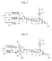
Fig. 5] Fig. 5 is a schematic flow diagram showing one embodiment of a water treatment apparatus for seawater desalination according to a fresh water generation method of the invention, which has three branch lines. - [
Fig. 6] Fig. 6 is a schematic flow diagram showing one embodiment of a water treatment apparatus for seawater desalination according to a fresh water generation method of the invention, which has a pretreatment unit in each branch line. - [
Fig. 7] Fig. 7 is a flow diagram of a conventional water treatment apparatus for seawater desalination. - Preferred embodiments of the invention will be described below using the drawings. However, it should be understood that the scope of the invention is not limited thereby.
- As one example of a water treatment apparatus according to a fresh water generation method of the invention, seawater desalination reverse osmosis membrane apparatus in which raw water is branched into two lines is shown in
Fig. 1 . In the water treatment apparatus shown inFig. 1 ,raw water 1 is branched intosedimentation tanks pretreatment unit 4 by apretreatment feed pump 3, and the pretreated raw water is fed to a reverseosmosis membrane unit 7 by abooster pump 6 through anintermediate water tank 5. Permeate of the reverseosmosis membrane unit 7 is stored in aproduct water tank 9, and used through awater distributing line 10. Concentrate of the reverseosmosis membrane unit 7 is discharged to the outside of the system from a dischargingline 11 after recovering pressure energy through anenergy recovery unit 8. - Here, general separation treatment such as solid-liquid separation or adsorption separation can be applied as the
pretreatment unit 4. As the solid-liquid separation particularly suitable for the pretreatment of seawater desalination, a screen filter for removing milli-order matters, sand filtration or filter cloth for removing micron-order matters, a microfiltration membrane or an ultrafiltration membrane capable of removing submicron matters, a nanofiltration membrane capable of performing more precise filtration, and the like may be mentioned. In addition, it is also possible to efficiently remove organic matters and the like by applying a coagulant or an adsorbent, or using a coagulant or an adsorbent in combination with solid-liquid separation. - This example has a constitution that a difference in retention time occurs between the
sedimentation tanks sedimentation tanks - For example, when seawater near a river mouth is used as the raw water, fluctuations in sea level caused by tide have a great influence. Accordingly, in consideration of the fluctuations around a tidal cycle, namely 6.25 hours, approximately a half of 12.5 hours, the difference D in retention time is preferably set to from 4 hours to 8.5 hours, and more preferably set to from 5 hours to 7.5 hours [the embodiment of the above (7)]. Further, although there is also no particular limitation on the flow rates fed to the
sedimentation tanks Fig. 1 , thesedimentation tanks 2 for changing the retention time are provided in two lines. However, it is also a preferred embodiment to provide them in 3 lines or more, as exemplified inFig. 5 . When provided in n lines (with the proviso that n is a natural number of 3 or more), the difference D in retention time between the different lines is preferably set to (1/n) times or (1-1/n) times the water quality fluctuation cycle C. That is to say, more specifically, when seawater near a river mouth is used as the raw water, the difference D in retention time between the different lines is preferably set to from 8/n hours to 17/n hours, or from 8-8/n hours to 17-17/n hours [the embodiment of the above (8)]. - In the water treatment apparatus of
Fig. 1 , thesedimentation tanks - Furthermore, in
Fig. 1 , the difference in retention time is provided between thesedimentation tanks sedimentation tanks sedimentation tanks Fig. 1 . That is to say, it is preferred to feed the raw water to the respective branch lines substantially at the same time [the embodiment of the above (5)]. From this viewpoint, inFig. 1 , that function is given to thesedimentation tanks intermediate water tanks Fig. 2 , or to bothsedimentation tanks intermediate water tanks Fig. 3 . However, when fluctuatingraw water 1 is treated withpretreatment unit 4 as inFig. 2 , the load on thepretreatment unit 4 fluctuates by fluctuations in water quality of theraw water 1. Accordingly, when a situation where fluctuations in the load on thepretreatment unit 4 are large to cause operation difficulty is assumed, it is unfavorable to give the function of providing the difference in retention time to theintermediate water tanks sedimentation tanks pretreatment unit 4 is designed so as to withstand the fluctuations in the load, conversely, environmental changes of thepretreatment unit 4 become large, leading to risk reduction of the propagation of living organisms. It is therefore a preferred embodiment to give the function of providing the difference in retention time to both thesedimentation tanks intermediate water tanks - Further, in the case having the function of providing the plural differences in retention time, like the sedimentation tanks and the intermediate water tanks as shown in
Fig. 3 , the total of the respective differences in retention time of thesedimentation intermediate water tanks sedimentation tanks intermediate water tanks Fig. 3 is extremely effective. - The water in which the fluctuations in raw water quality are suppressed according to the present invention can be subjected to various treatments in later stages. In particular, it is suitable to produce fresh water with reverse osmosis membrane water treatment apparatus in which operating pressure or product water quality fluctuates by the raw water concentration as exemplified in
Fig. 1 , especially by seawater desalination in which fluctuations in osmosis pressure are large and fluctuations in product water quality are also large [the embodiment of the above (9)]. Further, this is also suitable for biological treatment in which stable treatment becomes difficult by the fluctuations in raw water quality [the embodiment of the above (10)]. A membrane bioreactor involving the biological treatment is exemplified inFig. 4 . - By the way, as the raw water suitable for the present invention, suitable is one in which the fluctuations in water quality having influences on operating conditions or the product water quality are large. The present invention is also suitable for treatment of seawater having a high salt concentration as described above or brine water, and suitable for treatment of sewage wastewater or the like having large fluctuations not only in salt concentration, but also in organic matter concentration. Specifically, when the total salt concentration of the raw water fluctuates twice or more for one year, the present invention can be suitably utilized [the embodiment of the above (11)]. Further, also when the concentration of organic matter in the raw water fluctuates twice or more for one year, the present invention can be suitably utilized. Here, for the fluctuation widths of the total salt concentration and the organic matter concentration, the maximum values and minimum values thereof are defined by the maximum values and minimum values of the total salt concentration and the like obtained by monitoring the raw water quality for one year. In the present invention, it is preferred that the ratio of the maximum value and minimum value thereof is 2 or more. Incidentally, as a measuring method of the total salt concentration of the raw water, there is exemplified a measuring method using the "total dissolved solid" concentration, in which the raw water is evaporated to dryness and the weight thereof is measured, or use of simply a conductance meter and a salinometer for converting it to the salt concentration. Further, as a measuring method of the organic matter concentration, the most common is a measuring method using TOC (total organic carbon) concentration as an index. However, in addition, there are exemplified measuring methods using COD (chemical oxygen demand), BOD (biological oxygen demand), UV (ultraviolet absorption), IR (infrared absorption) and GC-MS (gas chromatograph mass spectrometry) as indices.
- Further, in order to make the present invention more effective, it is also preferred to measure the raw water quality at the time of feeding the raw water and to take the water when the raw water quality satisfies predetermined conditions [the embodiment of the above (12)]. As the water quality as used herein, there is exemplified one having great influences on operating conditions of membrane separation in a later stage as described above. For example, in the case of the reverse osmosis membrane, there is exemplified the total salt concentration giving large fluctuations to the osmotic pressure, and in the case of the membrane bioreactor, there is exemplified the organic matter concentration or total salt concentration having great influences on biological activity or treatment efficiency. It is preferred to perform control so as to take the water when these raw water qualities are within the predetermined ranges.
- For example, when the raw water is seawater (total salt concentration: 1.5 to 3.5%) near a river mouth as described in the above-mentioned
Non-Patent Document 1, the osmotic pressure is reduced by 5 to 10 bar compared to the case of a total salt concentration of 3.5% by not taking seawater having a total salt concentration of 2.5% or more. It is therefore possible to reduce necessary specs of the booster pump, which also leads to a reduction in pressure (a reduction in required power) at the time of operation. This makes it easy to suppress the fluctuations in raw water concentration, which is the object of the present invention, and therefore is very preferred. However, when the threshold value is narrowed, the water intake available time is shortened. Accordingly, ability of an intake pump is increased, so that it is necessary to consider a cost balance. Incidentally, when this method is applied in the case where the seawater near a river mouth is used as the raw water, for example, a part of fluctuations in sea level caused by tide are not taken. Accordingly, the cycle with respect to the water intake becomes shorter than 12.5 hours, so that it is preferred to make shorter than "approximately a half of 12.5 hours" described above. Specifically, when the water intake available time per day is T hours, the difference D in retention time is preferably set to approximately C×T/48 (for example, in the case of T=12 hours, from 6 hours to 6.5 hours). Of course, it is also a preferred embodiment to provide thesedimentation tanks 2 and the like for changing the retention time in 3 lines or more. In the case of n lines, it is preferred to set the difference D in retention time to T/24/n times or T/24×(1-1/n) times the water quality fluctuation cycle C. - Further, when the concentration of concentrate of the reverse
osmosis membrane unit 7 is smaller than the concentration of theraw water 1 at the time of inflow, it is also possible to recirculate the concentrate by openingvalves Fig. 3 . InFig. 3 , the concentrate is recirculated to before thesedimentation tanks sedimentation tanks intermediate water tanks product water tanks 9 asproduct water tanks way valve 13 for the fluctuations in product water quality, thereby suppressing the fluctuations, as exemplified inFig. 3 . Specifically, for example, the average concentration of 9a and 9b can be obtained by periodical switching to theproduct water tanks product water tank - Further, in the present invention, the water stabilized in water quality after branched and mixed can also be treated with the
pretreatment unit 4, as shown inFig. 1 , and the water can also be treated with thepretreatment unit 4 before branched, as shown inFig. 2 . Furthermore, as exemplified inFig. 6 , it is also preferred to shift the retention time of water after branched usingsedimentation tanks pretreatment units pretreatment units - The present invention can be utilized in a fresh water generation method for stably and efficiently obtaining product water satisfying target water quality by treating raw water such as seawater, river water, groundwater or treated wastewater.
-
- 1: Raw water
- 2: Sedimentation tank
- 3: Raw water feed pump
- 4: Pretreatment unit
- 5: Intermediate water tank
- 6: Booster pump
- 7: Reverse osmosis membrane unit
- 8: Energy recovery unit
- 9: Treated water tank
- 10: Water distributing line
- 11: Discharging line
- 12: Valve
- 13: Three-way valve
- 14: Suction pump
- 15: Biological treatment water tank
- 16: Submerged type membrane
Claims (12)
- A fresh water generation method for obtaining product water by treating raw water, the method comprising branching at least a part of a water flow line through which raw water flows into a plurality of branch lines including a branch line A1 and a branch line A2 and differentiating retention times from branching to joining together between the branch line A1 and the branch line A2.
- The fresh water generation method according to claim 1, wherein a volume of the branch line A1 is differentiated from a volume of the branch line A2.
- The fresh water generation method according to claim 1 or 2, wherein a feed flow rate to the branch line A1 is made to be substantially equivalent to a feed flow rate to the branch line A2.
- The fresh water generation method according to any one of claims 1 to 3, wherein the branch line A1 and the branch line A2 have a function of sedimentation separation.
- The fresh water generation method according to any one of claims 1 to 4, wherein the raw water is fed to the branch line A1 and the branch line A2 substantially at the same time.
- The fresh water generation method according to any one of claims 1 to 5, wherein the retention times after branched are differentiated between the branch line A1 and the branch line A2, and thereafter a treatment is performed with a pretreatment unit in each branch line of the branch line A1 and the branch line A2, followed by joining together.
- The fresh water generation method according to any one of claims 1 to 6, wherein a difference between the retention time in the branch line A1 and the retention time in the branch line A2 is from 4 hours to 8.5 hours.
- The fresh water generation method according to any one of claims 1 to 6, wherein the branch lines comprise n lines (with the proviso that n is a natural number of 3 or more), and a difference in retention time between the different lines is from 8/n hours to 17/n hours, or from 8-8/n hours to 17-17/n hours.
- The fresh water generation method according to any one of claims 1 to 8, wherein fresh water is produced using the raw water joined together from the plurality of branch lines.
- The fresh water generation method according to any one of claims 1 to 8, wherein biological treatment is performed using the raw water joined together from the plurality of branch lines.
- The fresh water generation method according to any one of claims 1 to 10, wherein a total salt concentration of the raw water fluctuates twice or more for one year.
- The fresh water generation method according to any one of claims 1 to 11, wherein raw water quality is measured at the time of feeding the raw water to the branch line A1 and the branch line A2, when the raw water quality satisfies predetermined conditions, the raw water is taken, and when the raw water quality does not satisfy the conditions, the raw water is fed to neither the branch line A1 nor the branch line A2.
Applications Claiming Priority (2)
| Application Number | Priority Date | Filing Date | Title |
|---|---|---|---|
| JP2011182206 | 2011-08-24 | ||
| PCT/JP2012/071035 WO2013027713A1 (en) | 2011-08-24 | 2012-08-21 | Fresh water generation method |
Publications (2)
| Publication Number | Publication Date |
|---|---|
| EP2749538A1 true EP2749538A1 (en) | 2014-07-02 |
| EP2749538A4 EP2749538A4 (en) | 2014-11-19 |
Family
ID=47746452
Family Applications (1)
| Application Number | Title | Priority Date | Filing Date |
|---|---|---|---|
| EP20120826357 Withdrawn EP2749538A4 (en) | 2011-08-24 | 2012-08-21 | Fresh water generation method |
Country Status (5)
| Country | Link |
|---|---|
| US (1) | US9878269B2 (en) |
| EP (1) | EP2749538A4 (en) |
| JP (2) | JP6051867B2 (en) |
| CN (1) | CN103748040B (en) |
| WO (1) | WO2013027713A1 (en) |
Cited By (1)
| Publication number | Priority date | Publication date | Assignee | Title |
|---|---|---|---|---|
| CN105999842A (en) * | 2016-07-21 | 2016-10-12 | 江苏展宏环保科技有限公司 | Coal wastewater purifier |
Families Citing this family (1)
| Publication number | Priority date | Publication date | Assignee | Title |
|---|---|---|---|---|
| KR20210092002A (en) * | 2020-01-15 | 2021-07-23 | 삼성전자주식회사 | Water purifier |
Family Cites Families (28)
| Publication number | Priority date | Publication date | Assignee | Title |
|---|---|---|---|---|
| JPS5794389A (en) | 1980-12-05 | 1982-06-11 | Hitachi Ltd | Sludge concentrating method |
| DE3125452C2 (en) * | 1981-06-29 | 1985-09-12 | Degussa Ag, 6000 Frankfurt | Process for detoxifying and lowering the COD and the BOD in continuous wastewater streams with changing contents of various oxidizable ingredients with hydrogen peroxide |
| US4608179A (en) * | 1983-10-19 | 1986-08-26 | Deal Troy M | Continuous process for the dewatering of phosphate slimes |
| JPH05337488A (en) | 1992-04-11 | 1993-12-21 | Hiroshi Kuwajima | Device for purifying general household waste water |
| KR930021554A (en) | 1992-04-11 | 1993-11-22 | 히로시 구와시마 | Sewage Purification Method and Sewage Purification Device |
| JP3468784B2 (en) * | 1992-08-25 | 2003-11-17 | 栗田工業株式会社 | Ultrapure water production equipment |
| JPH06218390A (en) | 1993-01-26 | 1994-08-09 | Keizo Watanabe | Waste water treatment device |
| JP3270211B2 (en) | 1993-09-02 | 2002-04-02 | 株式会社竹中工務店 | Freshwater production equipment |
| US5547584A (en) * | 1994-03-17 | 1996-08-20 | Electronic Drilling Control, Inc. | Transportable, self-contained water purification system and method |
| US5558775A (en) * | 1994-11-01 | 1996-09-24 | Joseph Busch, Jr. | Process for the treatment of hazardous waste water |
| JP3477526B2 (en) * | 1997-05-27 | 2003-12-10 | 日立造船株式会社 | Wastewater recovery equipment |
| US6241896B1 (en) * | 1999-03-05 | 2001-06-05 | Associated Water Industries, L.L.C. | Auto dosage determination method and apparatus for coagulant control in the treatment of water |
| US8512571B2 (en) * | 2002-06-03 | 2013-08-20 | Jonathan M. Dietz | Treatment of iron contaminated liquids with an activated iron solids (AIS) process |
| JP2004058026A (en) | 2002-07-31 | 2004-02-26 | Nitto Seiko Co Ltd | Automatic drug injection switching device |
| US8071055B2 (en) * | 2002-12-04 | 2011-12-06 | Blue Water Technologies, Inc. | Water treatment techniques |
| JP4357206B2 (en) * | 2003-04-16 | 2009-11-04 | 株式会社クボタ | Treatment system using membrane separation activated sludge method |
| US7484413B2 (en) | 2003-12-12 | 2009-02-03 | The Boeing Company | Remote radius inspection tool for composite joints |
| JP4284700B2 (en) | 2004-03-25 | 2009-06-24 | 株式会社日立プラントテクノロジー | Nitrogen removal method and apparatus |
| US7985345B2 (en) * | 2004-03-29 | 2011-07-26 | Innoventor, Inc. | Methods and systems for converting waste into complex hydrocarbons |
| CA2499656A1 (en) * | 2005-03-03 | 2006-09-03 | Udo Staschik | Method and portable apparatus for in-transport treatment of waste |
| JP2008307487A (en) * | 2007-06-15 | 2008-12-25 | Mitsubishi Heavy Ind Ltd | Desalting device |
| KR100837698B1 (en) * | 2007-09-03 | 2008-06-13 | 주식회사 피엠씨코리아 | Sludge Advanced Treatment System and Method |
| FR2930540B1 (en) * | 2008-04-24 | 2012-09-28 | Otv Sa | METHOD OF TREATING MEMBRANE STATION RELEASES |
| KR20110076872A (en) * | 2008-11-28 | 2011-07-06 | 가부시키가이샤 신꼬오 간쿄우 솔루션 | Desalination Method, Desalination System, Desalination Method and Desalination System |
| CA2760807A1 (en) * | 2009-05-14 | 2010-11-18 | Omni Water Solutions Llc | Self-contained portable multi-mode water treatment system and methods |
| US9126853B2 (en) * | 2009-08-21 | 2015-09-08 | Toray Industries, Inc. | Fresh water generator |
| AU2010334047B2 (en) | 2009-12-25 | 2015-11-05 | Toray Industries, Inc. | Water production system and operation method therefor |
| CN104661904B (en) | 2012-07-13 | 2017-06-20 | 日产自动车株式会社 | Front spoiler device |
-
2012
- 2012-08-21 JP JP2012539528A patent/JP6051867B2/en not_active Expired - Fee Related
- 2012-08-21 WO PCT/JP2012/071035 patent/WO2013027713A1/en not_active Ceased
- 2012-08-21 EP EP20120826357 patent/EP2749538A4/en not_active Withdrawn
- 2012-08-21 CN CN201280041111.6A patent/CN103748040B/en not_active Expired - Fee Related
- 2012-08-21 US US14/239,911 patent/US9878269B2/en active Active
-
2016
- 2016-11-29 JP JP2016230956A patent/JP6344457B2/en not_active Expired - Fee Related
Cited By (1)
| Publication number | Priority date | Publication date | Assignee | Title |
|---|---|---|---|---|
| CN105999842A (en) * | 2016-07-21 | 2016-10-12 | 江苏展宏环保科技有限公司 | Coal wastewater purifier |
Also Published As
| Publication number | Publication date |
|---|---|
| US20140190909A1 (en) | 2014-07-10 |
| JP6051867B2 (en) | 2016-12-27 |
| EP2749538A4 (en) | 2014-11-19 |
| CN103748040A (en) | 2014-04-23 |
| WO2013027713A1 (en) | 2013-02-28 |
| US9878269B2 (en) | 2018-01-30 |
| CN103748040B (en) | 2016-05-11 |
| JP2017039136A (en) | 2017-02-23 |
| JP6344457B2 (en) | 2018-06-20 |
| JPWO2013027713A1 (en) | 2015-03-19 |
Similar Documents
| Publication | Publication Date | Title |
|---|---|---|
| Vinardell et al. | Techno-economic analysis of combining forward osmosis-reverse osmosis and anaerobic membrane bioreactor technologies for municipal wastewater treatment and water production | |
| AU2009320741B2 (en) | Generation of fresh water | |
| Holloway et al. | Life-cycle assessment of two potable water reuse technologies: MF/RO/UV–AOP treatment and hybrid osmotic membrane bioreactors | |
| Jin et al. | Efficient sewage pre-concentration with combined coagulation microfiltration for organic matter recovery | |
| CN102596822B (en) | Water production system and operation method therefor | |
| CN102471102B (en) | Fresh water generator | |
| Turker et al. | Long term performance of a pilot scale anaerobic membrane bioreactor treating beet molasses based industrial wastewater | |
| AU2010293661B2 (en) | Fresh water production method and fresh water production device | |
| PL173335B1 (en) | Method of and apparatus for increasing concentration of solutions | |
| Echevarría et al. | Hybrid sorption and pressure-driven membrane technologies for organic micropollutants removal in advanced water reclamation: A techno-economic assessment | |
| Pervov et al. | Application of reverse osmosis to treat high ammonia concentrated reject water from sewage sludge digestion | |
| CN109071274B (en) | Method of power generation using osmotic and anaerobic wastewater treatment | |
| Darwish et al. | Needed seawater reverse osmosis pilot plant in Qatar | |
| US9878269B2 (en) | Fresh water generation method | |
| Ferrari | Combining forward osmosis and anaerobic membrane bioreactor technologies for raw municipal wastewater treatment | |
| AU2011253944B2 (en) | Generation of fresh water | |
| KR20240072636A (en) | Sea water desalting system for controlling concentration of concentrated water, and process operating method for the same | |
| Gong et al. | Evaluation of direct water reclamation from municipal wastewater by disk tube reverse osmosis membrane (DT-RO) based compact process | |
| Sun et al. | Continuous pilot-scale operation using FO membranes to concentrate municipal wastewater with artificial seawater as draw solution | |
| do Nascimento | Direct ultrafiltration with membranes applied to the carbon recovery from municipal wastewater | |
| KR20230143763A (en) | A low-energy desalination system using mixed raw water from multiple sources | |
| Pentair | Aquatech secures Middle Eastern deal |
Legal Events
| Date | Code | Title | Description |
|---|---|---|---|
| PUAI | Public reference made under article 153(3) epc to a published international application that has entered the european phase |
Free format text: ORIGINAL CODE: 0009012 |
|
| 17P | Request for examination filed |
Effective date: 20140221 |
|
| AK | Designated contracting states |
Kind code of ref document: A1 Designated state(s): AL AT BE BG CH CY CZ DE DK EE ES FI FR GB GR HR HU IE IS IT LI LT LU LV MC MK MT NL NO PL PT RO RS SE SI SK SM TR |
|
| A4 | Supplementary search report drawn up and despatched |
Effective date: 20141022 |
|
| RIC1 | Information provided on ipc code assigned before grant |
Ipc: C02F 3/12 20060101ALI20141016BHEP Ipc: C02F 1/44 20060101ALI20141016BHEP Ipc: C02F 1/00 20060101AFI20141016BHEP Ipc: B01D 21/00 20060101ALI20141016BHEP |
|
| DAX | Request for extension of the european patent (deleted) | ||
| 17Q | First examination report despatched |
Effective date: 20170620 |
|
| GRAP | Despatch of communication of intention to grant a patent |
Free format text: ORIGINAL CODE: EPIDOSNIGR1 |
|
| STAA | Information on the status of an ep patent application or granted ep patent |
Free format text: STATUS: GRANT OF PATENT IS INTENDED |
|
| INTG | Intention to grant announced |
Effective date: 20181206 |
|
| STAA | Information on the status of an ep patent application or granted ep patent |
Free format text: STATUS: THE APPLICATION IS DEEMED TO BE WITHDRAWN |
|
| 18D | Application deemed to be withdrawn |
Effective date: 20190417 |