EP2749067B1 - Procedure latency based admission control node, method and system - Google Patents
Procedure latency based admission control node, method and system Download PDFInfo
- Publication number
- EP2749067B1 EP2749067B1 EP11797037.6A EP11797037A EP2749067B1 EP 2749067 B1 EP2749067 B1 EP 2749067B1 EP 11797037 A EP11797037 A EP 11797037A EP 2749067 B1 EP2749067 B1 EP 2749067B1
- Authority
- EP
- European Patent Office
- Prior art keywords
- procedure
- delta
- monitor unit
- high load
- node
- Prior art date
- Legal status (The legal status is an assumption and is not a legal conclusion. Google has not performed a legal analysis and makes no representation as to the accuracy of the status listed.)
- Active
Links
- 238000000034 method Methods 0.000 title claims description 292
- 238000005259 measurement Methods 0.000 claims description 91
- 230000007246 mechanism Effects 0.000 claims description 32
- 230000009471 action Effects 0.000 claims description 16
- 238000012544 monitoring process Methods 0.000 claims description 7
- 230000003213 activating effect Effects 0.000 claims description 2
- 230000000903 blocking effect Effects 0.000 claims 2
- 230000006870 function Effects 0.000 description 11
- 230000008901 benefit Effects 0.000 description 7
- 238000010586 diagram Methods 0.000 description 5
- 230000001965 increasing effect Effects 0.000 description 5
- 230000011664 signaling Effects 0.000 description 3
- 230000001960 triggered effect Effects 0.000 description 3
- 102100039358 3-hydroxyacyl-CoA dehydrogenase type-2 Human genes 0.000 description 2
- 241001481828 Glyptocephalus cynoglossus Species 0.000 description 2
- 101001035740 Homo sapiens 3-hydroxyacyl-CoA dehydrogenase type-2 Proteins 0.000 description 2
- 230000002159 abnormal effect Effects 0.000 description 2
- 230000002411 adverse Effects 0.000 description 2
- 230000006399 behavior Effects 0.000 description 1
- 230000001419 dependent effect Effects 0.000 description 1
- 238000013461 design Methods 0.000 description 1
- 230000000694 effects Effects 0.000 description 1
- 230000002708 enhancing effect Effects 0.000 description 1
- 238000011156 evaluation Methods 0.000 description 1
- 230000007774 longterm Effects 0.000 description 1
- 238000010295 mobile communication Methods 0.000 description 1
- 238000012986 modification Methods 0.000 description 1
- 230000004048 modification Effects 0.000 description 1
- 238000012545 processing Methods 0.000 description 1
- 230000008707 rearrangement Effects 0.000 description 1
- 238000010972 statistical evaluation Methods 0.000 description 1
- 238000006467 substitution reaction Methods 0.000 description 1
Images


Classifications
-
- H—ELECTRICITY
- H04—ELECTRIC COMMUNICATION TECHNIQUE
- H04W—WIRELESS COMMUNICATION NETWORKS
- H04W28/00—Network traffic management; Network resource management
- H04W28/02—Traffic management, e.g. flow control or congestion control
-
- H—ELECTRICITY
- H04—ELECTRIC COMMUNICATION TECHNIQUE
- H04L—TRANSMISSION OF DIGITAL INFORMATION, e.g. TELEGRAPHIC COMMUNICATION
- H04L43/00—Arrangements for monitoring or testing data switching networks
- H04L43/08—Monitoring or testing based on specific metrics, e.g. QoS, energy consumption or environmental parameters
- H04L43/0852—Delays
-
- H—ELECTRICITY
- H04—ELECTRIC COMMUNICATION TECHNIQUE
- H04L—TRANSMISSION OF DIGITAL INFORMATION, e.g. TELEGRAPHIC COMMUNICATION
- H04L43/00—Arrangements for monitoring or testing data switching networks
- H04L43/16—Threshold monitoring
-
- H—ELECTRICITY
- H04—ELECTRIC COMMUNICATION TECHNIQUE
- H04L—TRANSMISSION OF DIGITAL INFORMATION, e.g. TELEGRAPHIC COMMUNICATION
- H04L47/00—Traffic control in data switching networks
- H04L47/70—Admission control; Resource allocation
- H04L47/82—Miscellaneous aspects
- H04L47/824—Applicable to portable or mobile terminals
-
- H—ELECTRICITY
- H04—ELECTRIC COMMUNICATION TECHNIQUE
- H04L—TRANSMISSION OF DIGITAL INFORMATION, e.g. TELEGRAPHIC COMMUNICATION
- H04L47/00—Traffic control in data switching networks
- H04L47/70—Admission control; Resource allocation
- H04L47/82—Miscellaneous aspects
- H04L47/826—Involving periods of time
-
- H—ELECTRICITY
- H04—ELECTRIC COMMUNICATION TECHNIQUE
- H04L—TRANSMISSION OF DIGITAL INFORMATION, e.g. TELEGRAPHIC COMMUNICATION
- H04L47/00—Traffic control in data switching networks
- H04L47/70—Admission control; Resource allocation
- H04L47/83—Admission control; Resource allocation based on usage prediction
-
- H—ELECTRICITY
- H04—ELECTRIC COMMUNICATION TECHNIQUE
- H04W—WIRELESS COMMUNICATION NETWORKS
- H04W24/00—Supervisory, monitoring or testing arrangements
- H04W24/10—Scheduling measurement reports ; Arrangements for measurement reports
Definitions
- the present invention relates to a wireless telecommunication system, a node (e.g.. eNodeB. eNB. BSC, RNC), a procedure latency monitor unit, and a method for measuring the latency of a procedure e.g.. radio network procedure, core network procedure where the results of the measured latency may be used for admission control of user equipment (UE) sessions and to guarantee that admitted UEs are served according to their requested Quality of Service (QoS).
- a procedure e.g.. radio network procedure, core network procedure
- QoS Quality of Service
- admission control is a function implemented in the node (e.g.. eNodeB. BSC, RNC) that manages a number of UE sessions.
- Admission control is needed to handle new, ongoing and incoming UE connections due to e.g. handover or roaming or establishment of connections, and to guarantee that admitted UEs are served according to their requested Quality of Service (QoS).
- QoS Quality of Service
- admission control is needed when the offered load is much higher than the node's engineered capacity. For example, when the node (e.g.. eNodeB. BSC, RNC) encounters a situation with high load, the node's admission control mechanism has the responsibility to throttle (e.g.. reduce) the load so it remains within the node's engineered capacity. This is valid for ongoing, new and incoming UE connections due to e.g. handover.
- throttle e.g. reduce
- the eNodeB's admission control mechanism uses both hard limits (e.g., the number of licenses in use) and dynamic limits (e.g.. the utilization ratio of the PRB resources).
- the eNodeB is configured to implement its own utilization measure for each internal resource that is a potential bottleneck. And, during the eNodeB operation a different type of traffic pattern will create its own particular bottlenecks.
- the eNodeB's internal resources may be for example:
- a prior art document WO 02/056564 A1 discloses a network resource manager (NRM) that can be implemented in a node of a wireless telecommunications for administrating a number of resources within the network.
- NEM network resource manager
- a node e.g., eNodeB, eNB, BSC, RNC
- a procedure latency monitor unit e.g., a method, and a wireless telecommunication system
- Advantageous embodiments of the node e.g., eNodeB, eNB, BSC, RNC
- the procedure latency monitor unit the method, and the wireless telecommunication system have been described in the dependent claims of the present application.
- a node located in a wireless telecommunications network and configured to administer a number of sessions with UEs.
- the node comprises a procedure latency monitor unit and an admission control mechanism.
- the procedure latency monitor unit is configured to establish a measurement window associated with a procedure within the wireless telecommunications network and during the measurement window is further configured to measure a predetermined number of delta times, where each measured delta time indicates an amount of time that takes place between a start of the procedure and a stop of the procedure.
- the procedure latency monitor unit upon completion of the measurement window is configured to take the predetermined number of measured delta times and is further configured to calculate a mean delta time which is an average of the measured delta times.
- the procedure latency monitor unit is configured to compare the mean delta time with a predetermined threshold which is also associated with the procedure and if the mean delta time exceeds the threshold then the procedure latence monitor unit is configured to issue a high load signal associated with the procedure.
- the admission control mechanism is configured to receive the high load signal associated with the procedure and is further configured to activate an admission action.
- a method implemented by a node located in a wireless telecommunications network and configured to administer a number of sessions with UEs.
- the method comprises: (a) establishing, in a procedure latency monitor unit, a measurement window associated with a procedure within the wireless telecommunications network and during the measurement window measuring a predetermined number of delta times, where each measured delta time indicates an amount of time that takes place between a start of the procedure and a stop of the procedure: (b) taking, in the procedure latency monitor unit, the predetermined number of measured delta times upon completion of the measurement window and calculating a mean delta time which is an average of the measured delta times: (c) comparing, in the procedure latency monitor unit, the mean delta time with a predetermined threshold which is also associated with the procedure and if the mean delta time exceeds the threshold then issuing a high load signal associated with the procedure; and (d) receiving, at an admission control mechanism, the high
- a procedure latency monitor unit which is part of a wireless telecommunication network.
- the procedure latency monitor unit comprises a processor and a memory that stores processor-executable instructions therein where the processor interfaces with the memory and executes the processor-executable instructions to enable the following: (a) establish a measurement window associated with a procedure within the wireless telecommunications network and during the measurement window measure a predetermined number of delta times, where each measured delta time indicates an amount of time that takes place between a start of the procedure and a stop of the procedure: (b) take the predetermined number of measured delta times upon completion of the measurement window and calculate a mean delta time which is an average of the measured delta times: and (c) compare the mean delta time with a predetermined threshold which is also associated with the procedure and if the mean delta time exceeds the threshold then issue a high load signal associated with the procedure.
- An advantage of the procedure latency monitor unit is that it enables the node to better steer the admission control function and determine when an internal resource has reached its engineered capacity.
- a method implemented by a procedure latency monitor unit which is located in a wireless telecommunications network comprises: (a) establishing a measurement window associated with a procedure within the wireless telecommunications network and during the measurement window measuring a predetermined number of delta times, where each measured delta time indicates an amount of time that takes place between a start of the procedure and a stop of the procedure: (b) taking the predetermined number of measured delta times upon completion of the measurement window and calculating a mean delta time which is an average of the measured delta times: and (c) comparing the mean delta time witch a predetermined threshold which is also associated with the procedure and if the mean delta time exceeds the threshold then issuing a high load signal associated with the procedure.
- a wireless telecommunications network which comprises a core network and a node (e.g.. eNodeB. eNB, BSC, RNC) connected to the core network and configured to administer a number of sessions with UEs.
- the node comprises a procedure latency monitor unit and an admission control mechanism.
- the procedure latency monitor unit is configured to establish a measurement window associated with a procedure within the wireless telecommunications network and during the measurement window is further configured to measure a predetermined number of delta times, where each measured delta time indicates an amount of time that takes place between a start of the procedure and a stop of the procedure.
- the procedure latency monitor unit upon completion of the measurement window is configured to take the predetermined number of measured delta times and is further configured to calculate a mean delta time which is an average of the measured delta times.
- the procedure latency monitor unit is configured to compare the mean delta time with a predetermined threshold which is also associated with the procedure and if the mean delta time exceeds the threshold then the procedure latency monitor unit is configured to issue a high load signal associated with the procedure.
- the admission control mechanism is configured to receive the high load signals associated with the procedure and is further configured to activate an admission action.
- a procedure latency monitor unit which is located in a wireless telecommunications network.
- the procedure latency monitor unit comprises a processor and a memory that stores processor-executable instructions therein where the processor interfaces with the memory and executes the processor-executable instructions to enable the following: (a) establish a measurement window when a procedure in the wireless telecommunications network has a delta time that exceeds a predetermined threshold, where the delta time is an amount of time that takes place between a start of the procedure and a stop of the procedure; (b) set a number of delta time measurements for the procedure that are to be completed during the measurement window: (c) wait for the procedure to occur: (d) when the procedure occurs, calculate a delta time which indicates an amount of time that takes place between a start of the procedure and a stop of the procedure; (e) decrement by one the number of delta time measurements that need to be completed during the measurement window; (f) determine if completed all of the delta time measurements that were set to be completed during the measurement window; (
- a method implemented by a procedure latency monitor unit which is located in a wireless telecommunications network comprises: (a) establishing a measurement window when a procedure in the wireless telecommunications nework has a delta time that exceeds a predetermined threshold, where the delta time is an amount of time that takes place between a start of the procedure and a stop of the procedure: (b) setting a number of delta time measurements for the procedure that are to be completed during the measurement window: (c) waiting for the procedure to occur: (d) when the procedure occurs, calculating a delta time which indicates an amount of time that takes place between a start of the procedure and a stop of the procedure: (e) decrementing by one the number of delta time measurements that need to be completed during the measurement window; (f) determining if completed all of the delta time measurements that were set to be completed during the measurement window; (g) if the result of the determining step is no.
- FIGURE 1 there is a block diagram of an exemplary LTE wireless telecommunication system 100 which has eNodeBs 102a. 102b and 102c (only three shown) each configured in accordance with an embodiment of the present invention.
- the LTE wireless telecommunication system 100 includes a MME/S-GW 104 (e.g.. core network 104) which has Sl interfaces with the three eNodeBs 102a. 102b and 102c.
- the eNodeBs 102a. 102b and 102c respectively manage their own cells 106a. 106b and 106c which have their own radio cover areas within which there may be one or more UEs 108.
- the exemplary LTE wireless telecommunication system 100 may support many UEs 108 and includes many other components which are well known in the art but for clarity are not described herein while the eNodeBs 102a, 102b and 102c or nodes in accordance with the presently described exemplary embodiments are described in detail herein. A detailed description is provided next to explain how the eNodeBs 102a. 102b and 102c are configured to address the shortcomings of the prior art and improve the admission control function to better handle new, ongoing and incoming UE connections.
- the eNodeBs 102a. 102b and 102c also have many well known components (e.g.. receiver, transmitter) incorporated therein but for clarity those well known components are not described herein.
- the eNodeB 102a includes an admission control mechanism 202. a procedure latency monitor unit 204, and an optional traffic measurement unit 206.
- the procedure latency monitor unit 204 includes a processor 208 and a memory 210 that stores processor-executable instructions therein where the processor 208 interfaces with the memory 210 and executes the processor-executable instructions to enable the following: (a) establish a measurement window 212 associated with a procedure 214 within the wireless telecommunications network 100 and during the measurement window 212 measures a predetermined number of delta times 216, where each measured delta time 216 indicates an amount of time that takes place between a start 218 of the procedure 214 and a stop 220 of the procedure 214 (step 302 in FIGURE.
- the traffic measurement unit 206 may be used in conjunction with the procedure latency monitor unit 204 to provide additional information 230 (e.g., dropped UE sessions 230) to the admission control mechanism 202.
- the traffic measurement unit 206 may be configured to determine the number of sessions with the UEs 108 which are dropped without being requested to be released by the UEs 108 and then report the number of dropped UE sessions 230 to the admission control mechanism 202.
- the admission control mechanism 202 upon receiving the high load signal 226 associated with the procedure 214 further determines if the number of dropped UE sessions 230 exceeds a predetermined threshold 232 and if yes then activates the admission action 228.
- the admission action 228 may include anyone or a combination of the following:
- the procedure latency monitor unit 204 may establish additional measurement windows 212' to measure additional delta times 16' for additional different procedures 214' and then calculate additional mean delta times 222' for the additional different procedures 214' where if one or more of the calculated mean delta times 222' exceed a corresponding threshold 224' then issue one or more high load signals 226 associated with the corresponding one or more different procedures 214'.
- the procedure latency monitor unit 204 for each additional monitored procedure 214' would: (a) establish a measurement window 212' associated with that procedure 214' within the wireless telecommunications network 100 and during the measurement window 212' measures a predetermined number of delta times 216', where each measured delta time 216' indicates an amount of time that takes place between a start 218' of that procedure 214' and a stop 220' of that procedure 214'; (b) take the predetermined number of measured delta times 216' upon completion of the measurement window 212' and calculate a mean delta time 222' which is an average of the measured delta times 216': and (c) compare the mean delta time 222' with a predetermined threshold 224' which is also associated with that procedure 214' and if the mean delta time 222' exceeds the threshold 224' then issue a high load signal 226 (e.g., raiseHighLoad (procedure) 226) associated with the procedure 214'.
- a high load signal 226 e.g
- the procedure latency monitor unit 204 issues the high load signal 226 which is associated with anyone of the procedures 214 or 214' then the processor 208 may further execute the processor-executable instructions to establish another measurement window 212 or 212' for that procedure 214 or 214' to measure multiple delta times 216 or 216' for that procedure 214 or 214' and then calculate the mean delta time 222 or 222' for that procedure 214 or 214' where if the calculated mean delta time 222 or 222' does not exceed the threshold 224 oar 224' for that procedure 214 or 214' then issue a cease high load signal 234 (e.g.. ceaseHighLoad (procedure) 234) associated with that procedure 214 or 214' (see step 308 in FIGURE 3 ).
- a cease high load signal 234 e.g.. ceaseHighLoad (procedure) 234
- the procedure latency monitor unit 204 may establish the measurement window 212 or 212' pursuant steps 302 or 308 when the corresponding procedure 214 or 214' has a delta time that exceeds a predetermined threshold 224 or 224' (or different threshold) where the delta time is an amount of time that takes place between a start 218 or 218' of the procedure 214 or 214' and a stop 220 or 220' of the procedure 214 or 214'.
- a predetermined threshold 224 or 224' or different threshold
- the eNodeB 102a (for example) described above provides a way of monitoring the procedures 214 and 214' (e.g.. radio network procedures, core network procedures) to trigger one or more admission control actions 228.
- the eNodeB 102a measures the latency of procedures 214 and 214' and when there is an increased procedure time then initiate admission control supervision.
- the eNodeB 102a measures the latency of procedures 214 and 214' and the dropped UE sessions 230 and when there is an increased procedure time and an increased UE drop rates then initiate admission control supervision.
- a threshold For every procedure 214 (for example) used in the supervision of the admission control, there is a defined threshold to 224.
- a delta time 216 that is measured for each procedure 214 (for example) which is the time between the start 218 of procedure 214 and the stop 220 of the procedure 214. If no measurement is ongoing for the procedure 214 (for example), then a new measurement window 212 may be established and subsequent delta time 216 measurements started when a delta time breaches the to threshold 224, i.e. when the first procedure 214 exceeded its maximum delay time (see FIGURE 4 ).
- the measurement window 212 is active for the procedure 214 (for example) until N delta times 216 have been collected (i.e.. N procedures 214 have started and completed). Once the measurement window 212 is closed, then a statistical evaluation of procedure delta times 216 may be performed so a determination may be made on whether or not any succeeding admission actions have to be performed, i.e. activate the admission control.
- the procedure latency monitor unit 204 calculates the procedure latency mean time (tPLM) 222 and 222' for the monitored procedure 214 and 214'.
- tPLM procedure latency mean time
- the procedure latency monitor unit 204 may collect procedure latency measurements 216 and 216' (delta times 216 and 216') simultaneously for all monitored procedures 214 and 214'. Admission control may be triggered if at least one procedure 214 and 214' has a mean delta time 222 and 222' which exceeds its threshold 224 and 224'.
- a possible enhancement is to include a dependency between procedure delta times such as follows: The formula above calculates a mean procedure time for all (N) measured procedures. In this case, the admission control is being triggered when all the mean time of all procedures exceeds the configured threshold for overload.
- the measurement window 212 and 212' shall be closed.
- a new measurement window 212 and 212' will be started when the next delta time 216 and 216' has breached the t 0 threshold 224 and 224' for that particular procedure 214 and 214'.
- Every monitored procedure 214 and 214' has a configurable threshold 224 and 224' at which the admission control mechanism 202 is triggered with a high load signal 226 (raiseHighLoad(procedure) 226).
- the actions 228 that may be performed by the admission control mechanism 202 upon receiving the high load signal 226 may include anyone or a combination of the following (for example):
- any outstanding admission action for that procedure 214 and 214' may be ceased by issuing the cease high load signal 234 (e.g., ceaseHighLoad (procedure) 234) towards the admission control mechanism 202.
- the cease high load signal 234 e.g., ceaseHighLoad (procedure) 234.
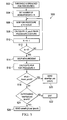
- FIGURE 5 there is a flowchart illustrating the basic steps of an exemplary method 500 implemented by the procedure latency monitor unit 204 in accordance with an embodiment of the present invention.
- the procedure 214 e.g., procedure A
- the delta time 216 is an amount of time that takes place between a start 218 of the procedure 214 and a stop 220 of the procedure 214.
- step 506. wait for the procedure 214 to occur.
- the delta time 216 which indicates an amount of time that takes place between the start 218 of the procedure 214 and the stop 220 of the procedure 214.
- calculate the mean delta time 222 which is an average of the measured delta times 216 for the procedure 214.
- step 518 check if the mean delta time 222 exceeds the predetermined threshold 224 which is associated with the procedure 214. If the result of the check step 518 is yes, then at step 520 send the high load signal 226 (raiseHighLoad(procedure) 226) associated with the procedure 214 to the admission control mechanism 202. If the result of the check step 518 is no, then at step 524 determine if there is an outstanding high load signal 226 that was previously sent and is still pending with the admission control mechanism 202. If the result of the determine step 524 is no then end at step 522. If the result of the determine step 524 is yes, then at step 526 send the cease high load signal 234 (e.g.. ceaseHighLoad (procedure) 234) associated with the procedure 214 to the admission control mechanism 202.
- the cease high load signal 234 e.g.. ceaseHighLoad (procedure) 234
- the new measure technique described above aims to cover all internal resources, e.g., if an internal resource is starting to reach its engineered capacity then this should be indicated (or predicted) by the measurement of one or more procedures regardless of the internal resource type.
- the new measure technique introduces a way to steer the admission control mechanism 202 and to determine if the internal resource of the eNodeB 102a (for example) has reached its engineered capacity or not by measuring the latency of procedure(s) 214 and 214' and if desired by monitoring the UE drop levels 230. For example, in a high load scenario it may be monitored that the completion times for the procedure(s) 214 and 214' are stretched and that abnormal UE drop levels 230 are increasing.
- An abnormal UE drop level 230 may be determined by monitoring UE Context drops or ERAB drops which occur when the eNodeB 102a (for example) or the core network performs a release of the UE 108, or a release of the data radio bearer used by the UE 108 without being requested by the UE 108. Both these drops will adversely impact the end user.
- the procedure latency monitor unit 204 may help accomplish this by implementing a method of measuring delta times 216 on procedures 214 and 214' (stop - start times). Then, when the monitored means delta time 222 for one or several procedures 214 and 214' has breached a certain threshold 224, when at the same time UE drop level 230 has increased (if this option is used), a high load signal 226 is sent to the admission control mechanism 202 which may then perform subsequent admission control actions 228.
- a method of measuring delta times 216 on procedures 214 and 214' stop - start times
- the procedure latency monitor unit 204 may identify when the eNodeB 102a (for example) is in a high load situation or is likely to reach a high load situation and give the admission control mechanism 202 an opportunity to reduce the affects of the high load situation or prevent the affects of the high load situation.
- the procedure latency monitor unit 204 is shown purely on eNodeB level, but it will also impact the core network's load as the signaling load between eNodeB and CN (e.g, MME/S-GW 104) will decrease. This is because the procedure latency measurements may include one or more procedures 214 and 214' that are CN procedure times, which provide end-to-end measurements, e.g., CN to RAN measurements.
- the admission control mechanism 202 is distributed amongst the eNodeBs 102a, 102b, and 102c (for example) in the network 100, so the embodiments of the present invention may also spare CN internal resources at high load scenarios since the eNodeBs 102a, 102b and 102c may, for example, block UE connections that would imply load to the CN.
- the exemplary embodiments of the present invention have been described above with respect to a LTE wireless telecommunications network and eNodeBs. However, the embodiments may be practiced in any type of wireless telecommunication network where there is a node (e.g., eNodeB, eNB, base station controller, RNC) that manages a cell in which a radio service may be provided to a UE 108.
- a node e.g., eNodeB, eNB, base station controller, RNC
- the present invention may be practiced in GSM. WCDMA or CDMA wireless telecommunication networks.
Description
- The present invention relates to a wireless telecommunication system, a node (e.g.. eNodeB. eNB. BSC, RNC), a procedure latency monitor unit, and a method for measuring the latency of a procedure e.g.. radio network procedure, core network procedure where the results of the measured latency may be used for admission control of user equipment (UE) sessions and to guarantee that admitted UEs are served according to their requested Quality of Service (QoS).
- The following abbreviations are herewith defined, at least some of which are referred to within the following description about at least the prior art and/or the present invention.
- BSC
- Base Station Controller
- CDMA
- Code Division Multiple Access
- CN
- Core Network
- CPU
- Central Processing Unit
- EPC
- Evolved Packet Core
- ERAB
- EUTRAN Radio Access Bearers
- GSM
- Global System for Mobile Communications
- LTE
- Long Term Evolution
- PLM
- Procedure Latency Monitor
- PRB
- Physical Resource Block
- QoS
- Quality of Service
- RAN
- Radio Access Network
- RNC
- Radio Network Controller
- RRC
- Radio Resource Control
- tPLM
- Procedure Latency Mean time
- UE
- User Equipment
- WCDMA
- Wideband Code Division Multiple Access
- In a wireless telecommunication system, admission control (capacity management) is a function implemented in the node (e.g.. eNodeB. BSC, RNC) that manages a number of UE sessions. Admission control is needed to handle new, ongoing and incoming UE connections due to e.g. handover or roaming or establishment of connections, and to guarantee that admitted UEs are served according to their requested Quality of Service (QoS). In addition, admission control is needed when the offered load is much higher than the node's engineered capacity. For example, when the node (e.g.. eNodeB. BSC, RNC) encounters a situation with high load, the node's admission control mechanism has the responsibility to throttle (e.g.. reduce) the load so it remains within the node's engineered capacity. This is valid for ongoing, new and incoming UE connections due to e.g. handover.
- For example, in LTE the eNodeB's admission control mechanism uses both hard limits (e.g., the number of licenses in use) and dynamic limits (e.g.. the utilization ratio of the PRB resources). Basically, the eNodeB is configured to implement its own utilization measure for each internal resource that is a potential bottleneck. And, during the eNodeB operation a different type of traffic pattern will create its own particular bottlenecks. Thus, when designing and programming or configuring the eNodeB it is difficult to predict which internal resources that will run out due to high traffic load and which internal resources that need to be monitored. The eNodeB's internal resources may be for example:
- Number of connected users
- Number of bearers per user (signaling and data)
- CPU utilization
- Signal buffer sizes
- Accordingly, there is and has been a need for enhancing the traditional node (e.g., eNodeB, BSC, RNC) to address these shortcomings and other shortcomings to improve at least the admission control function to handle new, ongoing and incoming UE connections. This need and other needs are satisfied by the exemplary embodiments of the present invention.
- A prior art document
WO 02/056564 A1 - A node (e.g., eNodeB, eNB, BSC, RNC), a procedure latency monitor unit, a method, and a wireless telecommunication system that address the shortcomings of the prior art are described in the independent claims of the present application. Advantageous embodiments of the node (e.g., eNodeB, eNB, BSC, RNC), the procedure latency monitor unit, the method, and the wireless telecommunication system have been described in the dependent claims of the present application.
- In an example there is provided a node (e.g., eNodeB, eNB, BSC, RNC) located in a wireless telecommunications network and configured to administer a number of sessions with UEs. The node comprises a procedure latency monitor unit and an admission control mechanism. The procedure latency monitor unit is configured to establish a measurement window associated with a procedure within the wireless telecommunications network and during the measurement window is further configured to measure a predetermined number of delta times, where each measured delta time indicates an amount of time that takes place between a start of the procedure and a stop of the procedure. In addition, the procedure latency monitor unit upon completion of the measurement window is configured to take the predetermined number of measured delta times and is further configured to calculate a mean delta time which is an average of the measured delta times. Furthermore, the procedure latency monitor unit is configured to compare the mean delta time with a predetermined threshold which is also associated with the procedure and if the mean delta time exceeds the threshold then the procedure latence monitor unit is configured to issue a high load signal associated with the procedure. The admission control mechanism is configured to receive the high load signal associated with the procedure and is further configured to activate an admission action. An advantage of the node is that it may better steer the admission control function and determine when an internal resource has reached its engineered capacity.
- In yet another example there is provided a method implemented by a node (e.g., eNodeB. eNB, BSC. RNC) located in a wireless telecommunications network and configured to administer a number of sessions with UEs. The method comprises: (a) establishing, in a procedure latency monitor unit, a measurement window associated with a procedure within the wireless telecommunications network and during the measurement window measuring a predetermined number of delta times, where each measured delta time indicates an amount of time that takes place between a start of the procedure and a stop of the procedure: (b) taking, in the procedure latency monitor unit, the predetermined number of measured delta times upon completion of the measurement window and calculating a mean delta time which is an average of the measured delta times: (c) comparing, in the procedure latency monitor unit, the mean delta time with a predetermined threshold which is also associated with the procedure and if the mean delta time exceeds the threshold then issuing a high load signal associated with the procedure; and (d) receiving, at an admission control mechanism, the high load signal associated with the procedure then activating an admission action. An advantage of the method is that it enables the node to better steer the admission control function and determine when an internal resource has reached its engineered capacity.
- In still yet another example there is provided a procedure latency monitor unit which is part of a wireless telecommunication network. The procedure latency monitor unit comprises a processor and a memory that stores processor-executable instructions therein where the processor interfaces with the memory and executes the processor-executable instructions to enable the following: (a) establish a measurement window associated with a procedure within the wireless telecommunications network and during the measurement window measure a predetermined number of delta times, where each measured delta time indicates an amount of time that takes place between a start of the procedure and a stop of the procedure: (b) take the predetermined number of measured delta times upon completion of the measurement window and calculate a mean delta time which is an average of the measured delta times: and (c) compare the mean delta time with a predetermined threshold which is also associated with the procedure and if the mean delta time exceeds the threshold then issue a high load signal associated with the procedure. An advantage of the procedure latency monitor unit is that it enables the node to better steer the admission control function and determine when an internal resource has reached its engineered capacity.
- In yet another example there is provided a method implemented by a procedure latency monitor unit which is located in a wireless telecommunications network. The method comprises: (a) establishing a measurement window associated with a procedure within the wireless telecommunications network and during the measurement window measuring a predetermined number of delta times, where each measured delta time indicates an amount of time that takes place between a start of the procedure and a stop of the procedure: (b) taking the predetermined number of measured delta times upon completion of the measurement window and calculating a mean delta time which is an average of the measured delta times: and (c) comparing the mean delta time witch a predetermined threshold which is also associated with the procedure and if the mean delta time exceeds the threshold then issuing a high load signal associated with the procedure. An advantage of the method is that it enables the node to better steer the admission control function and determine when an internal resource has reached its engineered capacity.
- In still yet another example there is provided a wireless telecommunications network which comprises a core network and a node (e.g.. eNodeB. eNB, BSC, RNC) connected to the core network and configured to administer a number of sessions with UEs. The node comprises a procedure latency monitor unit and an admission control mechanism. The procedure latency monitor unit is configured to establish a measurement window associated with a procedure within the wireless telecommunications network and during the measurement window is further configured to measure a predetermined number of delta times, where each measured delta time indicates an amount of time that takes place between a start of the procedure and a stop of the procedure. In addition, the procedure latency monitor unit upon completion of the measurement window is configured to take the predetermined number of measured delta times and is further configured to calculate a mean delta time which is an average of the measured delta times. Furthermore, the procedure latency monitor unit is configured to compare the mean delta time with a predetermined threshold which is also associated with the procedure and if the mean delta time exceeds the threshold then the procedure latency monitor unit is configured to issue a high load signal associated with the procedure. The admission control mechanism is configured to receive the high load signals associated with the procedure and is further configured to activate an admission action. An advantage of the node is that it may better steer the admission control function and determine when an internal resource has reached its engineered capacity.
- In yet another example there is provided a procedure latency monitor unit which is located in a wireless telecommunications network. The procedure latency monitor unit comprises a processor and a memory that stores processor-executable instructions therein where the processor interfaces with the memory and executes the processor-executable instructions to enable the following: (a) establish a measurement window when a procedure in the wireless telecommunications network has a delta time that exceeds a predetermined threshold, where the delta time is an amount of time that takes place between a start of the procedure and a stop of the procedure; (b) set a number of delta time measurements for the procedure that are to be completed during the measurement window: (c) wait for the procedure to occur: (d) when the procedure occurs, calculate a delta time which indicates an amount of time that takes place between a start of the procedure and a stop of the procedure; (e) decrement by one the number of delta time measurements that need to be completed during the measurement window; (f) determine if completed all of the delta time measurements that were set to be completed during the measurement window; (g) if the result of the determine step is no. then return and perform the wait operation; (h) if the result of the determine step is yes, then: (i) stop the delta time measurement: (ii) calculate a mean delta time which is an average of the measured delta times for the procedure: (iii) check if the mean delta time exceeds a predetermined threshold which is associated with the procedure: (iv) if the result of the check operation is yes, then send a high load signal associated with the procedure: and (v) if the result of the check operation is no, then determine if there is an outstanding high load signal and if not then end otherwise send a cease high load signal associated with the procedure. An advantage of the procedure latency monitor unit is that it enables the node to better steer the admission control function and determine when an internal resource has reached its engineered capacity.
- In still yet another example there is provided a method implemented by a procedure latency monitor unit which is located in a wireless telecommunications network. The method comprises: (a) establishing a measurement window when a procedure in the wireless telecommunications nework has a delta time that exceeds a predetermined threshold, where the delta time is an amount of time that takes place between a start of the procedure and a stop of the procedure: (b) setting a number of delta time measurements for the procedure that are to be completed during the measurement window: (c) waiting for the procedure to occur: (d) when the procedure occurs, calculating a delta time which indicates an amount of time that takes place between a start of the procedure and a stop of the procedure: (e) decrementing by one the number of delta time measurements that need to be completed during the measurement window; (f) determining if completed all of the delta time measurements that were set to be completed during the measurement window; (g) if the result of the determining step is no. then return and perform the waiting step: (h) if the result of the determining step is yes, then: (i) stopping the delta time measurement: (ii) calculating a mean delta time which is an average of the measured delta times for the procedure: (iii) checking if the mean delta time exceeds a predetermined threshold which is associated with the procedure; (iv) if the result of the checking step is yes, then sending a high load signal associated with the procedure: and (v) if the result of the checking is no. then determining if there is an outstanding high load signal and if not then end otherwise sending a cease high load signal associated with the procedure. An advantage of the method is that it enables the node to better steer the admission control function and determine when an internal resource has reached its engineered capacity.
- Additional examples will be set forth, in part, in the detailed description, figures and any claims which follow, and in part will be derived from the detailed description, or may be learned by practice of the exemplary embodiments of the present invention. It is to be understood that both the foregoing general description and the following detailed description are exemplary and explanatory only and are not restrictive of the invention as disclosed.
- A more complete understanding of the presently described embodiments may be obtained by reference to the following detailed description when taken in conjunction with the accompanying drawings:
-
FIGURE 1 is a block diagram of an exemplary LTE wireless telecommunication system which has eNodeBs configured in accordance with an embodiment of the present invention: -
FIGURE 2 is a block diagram that illustrates in greater detail the components in one of the eNodeBs shown inFIGURE 1 configured in accordance with an embodiment of the present invention: -
FIGURE 3 is a flowchart illustrating the basic steps of an exemplary method implemented by a procedure latency monitor unit (incorporated within the eNodeB) in accordance with an embodiment of the present invention: -
FIGURE 4 is a diagram illustrating used to help explain how the procedure latency monitor unit (incorporated within the eNodeB) may perform a latency procedure measurement in accordance with an embodiment of the present invention; and -
FIGURE 5 is a flowchart illustrating the basic steps of another exemplary method implemented by the procedure latency monitor unit (incorporated within the eNodeBs) in accordance with an embodiment of the present invention. - Referring to
FIGURE 1 . there is a block diagram of an exemplary LTEwireless telecommunication system 100 which haseNodeBs 102a. 102b and 102c (only three shown) each configured in accordance with an embodiment of the present invention. In this example, the LTEwireless telecommunication system 100 includes a MME/S-GW 104 (e.g.. core network 104) which has Sl interfaces with the threeeNodeBs 102a. 102b and 102c. TheeNodeBs 102a. 102b and 102c respectively manage theirown cells 106a. 106b and 106c which have their own radio cover areas within which there may be one ormore UEs 108. TheeNodeBs 102a. 102b and 102c utilize RRC signaling to interface with theirrespective UEs 108. In addition, theeNodeBs 102a. 102b and 102c communicate with one another over multiple X2 interfaces. The exemplary LTEwireless telecommunication system 100 may supportmany UEs 108 and includes many other components which are well known in the art but for clarity are not described herein while theeNodeBs eNodeBs 102a. 102b and 102c are configured to address the shortcomings of the prior art and improve the admission control function to better handle new, ongoing and incoming UE connections. TheeNodeBs 102a. 102b and 102c also have many well known components (e.g.. receiver, transmitter) incorporated therein but for clarity those well known components are not described herein. - Referring to
FIGURES 2 and3 , there are shown a block diagram and a flowchart respectively illustrating the eNodeB 102a (for example) and themethod 300 implemented therein in accordance with an exemplary embodiment of the present invention. As shown, theeNodeB 102a includes anadmission control mechanism 202. a procedurelatency monitor unit 204, and an optionaltraffic measurement unit 206. The procedurelatency monitor unit 204 includes aprocessor 208 and amemory 210 that stores processor-executable instructions therein where theprocessor 208 interfaces with thememory 210 and executes the processor-executable instructions to enable the following: (a) establish ameasurement window 212 associated with aprocedure 214 within thewireless telecommunications network 100 and during themeasurement window 212 measures a predetermined number ofdelta times 216, where each measureddelta time 216 indicates an amount of time that takes place between astart 218 of theprocedure 214 and astop 220 of the procedure 214 (step 302 inFIGURE. 3 )(see also description associated withFIGURE 4 ); (b) take the predetermined number of measureddelta times 216 upon completion of themeasurement window 212 and calculate amean delta time 222 which is an average of the measured delta times 216 (seestep 304 inFIGURE 3 ): and (c) compare themean delta time 222 with apredetermined threshold 224 which is also associated with theprocedure 214 and if themean delta time 222 exceeds thethreshold 224 then issue a high load signal 226 (e.g., raiseHighLoad (procedure) 226) associated with the procedure 214 (step 306 inFIGURE 3 ). Thereafter, theadmission control unit 202 upon receiving the high load signal 226 (e.g., raiseHighLoad (procedure) 226) associated witch theprocedure 214 is configured to activate anadmission action 228. - The
traffic measurement unit 206 may be used in conjunction with the procedurelatency monitor unit 204 to provide additional information 230 (e.g., dropped UE sessions 230) to theadmission control mechanism 202. For example, thetraffic measurement unit 206 may be configured to determine the number of sessions with theUEs 108 which are dropped without being requested to be released by theUEs 108 and then report the number ofdropped UE sessions 230 to theadmission control mechanism 202. Thereafter, theadmission control mechanism 202 upon receiving thehigh load signal 226 associated with theprocedure 214 further determines if the number ofdropped UE sessions 230 exceeds apredetermined threshold 232 and if yes then activates theadmission action 228. For example, theadmission action 228 may include anyone or a combination of the following: - Block one or more new UEs trying to connect to the eNodeB level.
- Release one or
more UEs 108 already connected based on a priority class; - Block a new data radio bearer setup.
- Release of one or more data radio bearers.
- Reduce observability monitoring.
- Etc.
- If desired, the procedure
latency monitor unit 204 may establish additional measurement windows 212' to measure additional delta times 16' for additional different procedures 214' and then calculate additional mean delta times 222' for the additional different procedures 214' where if one or more of the calculated mean delta times 222' exceed a corresponding threshold 224' then issue one or more high load signals 226 associated with the corresponding one or more different procedures 214'. In particular, the procedurelatency monitor unit 204 for each additional monitored procedure 214' would: (a) establish a measurement window 212' associated with that procedure 214' within thewireless telecommunications network 100 and during the measurement window 212' measures a predetermined number of delta times 216', where each measured delta time 216' indicates an amount of time that takes place between a start 218' of that procedure 214' and a stop 220' of that procedure 214'; (b) take the predetermined number of measured delta times 216' upon completion of the measurement window 212' and calculate a mean delta time 222' which is an average of the measured delta times 216': and (c) compare the mean delta time 222' with a predetermined threshold 224' which is also associated with that procedure 214' and if the mean delta time 222' exceeds the threshold 224' then issue a high load signal 226 (e.g., raiseHighLoad (procedure) 226) associated with the procedure 214'. For example, the procedurelatency monitor unit 204 may monitor one ormore procedures 214 and 214' which include radio network procedures and/or core network procedures such as anyone of the following: - a RRCConnectionSetup.
- an InitialContextSetup.
- an ERABSetup.
- a HandoverPrcparation.
- A procedure that interacts with another node other than
UEs 108. - Etc.
- Once, the procedure
latency monitor unit 204 issues thehigh load signal 226 which is associated with anyone of theprocedures 214 or 214' then theprocessor 208 may further execute the processor-executable instructions to establish anothermeasurement window 212 or 212' for thatprocedure 214 or 214' to measuremultiple delta times 216 or 216' for thatprocedure 214 or 214' and then calculate themean delta time 222 or 222' for thatprocedure 214 or 214' where if the calculatedmean delta time 222 or 222' does not exceed thethreshold 224 oar 224' for thatprocedure 214 or 214' then issue a cease high load signal 234 (e.g.. ceaseHighLoad (procedure) 234) associated with thatprocedure 214 or 214' (seestep 308 inFIGURE 3 ). - The procedure
latency monitor unit 204 may establish themeasurement window 212 or 212'pursuant steps corresponding procedure 214 or 214' has a delta time that exceeds apredetermined threshold 224 or 224' (or different threshold) where the delta time is an amount of time that takes place between astart 218 or 218' of theprocedure 214 or 214' and astop 220 or 220' of theprocedure 214 or 214'. A more detailed description about when themeasurement window 212 or 212' may be establishedpursuant steps FIGURE 4 . - As can be seen, the eNodeB 102a (for example) described above provides a way of monitoring the
procedures 214 and 214' (e.g.. radio network procedures, core network procedures) to trigger one or moreadmission control actions 228. In particular, theeNodeB 102a measures the latency ofprocedures 214 and 214' and when there is an increased procedure time then initiate admission control supervision. Alternatively, theeNodeB 102a measures the latency ofprocedures 214 and 214' and the droppedUE sessions 230 and when there is an increased procedure time and an increased UE drop rates then initiate admission control supervision. - For every procedure 214 (for example) used in the supervision of the admission control, there is a defined threshold to 224. In addition, there is a
delta time 216 that is measured for each procedure 214 (for example) which is the time between thestart 218 ofprocedure 214 and thestop 220 of theprocedure 214. If no measurement is ongoing for the procedure 214 (for example), then anew measurement window 212 may be established andsubsequent delta time 216 measurements started when a delta time breaches the tothreshold 224, i.e. when thefirst procedure 214 exceeded its maximum delay time (seeFIGURE 4 ). Themeasurement window 212 is active for the procedure 214 (for example) untilN delta times 216 have been collected (i.e..N procedures 214 have started and completed). Once themeasurement window 212 is closed, then a statistical evaluation ofprocedure delta times 216 may be performed so a determination may be made on whether or not any succeeding admission actions have to be performed, i.e. activate the admission control. - Referring to
FIGURE 4 . there is illustrated a latency measurement example where for procedure 214 (for example) there is anew measurement window 212 created when adelta time measurement 402 breaches the threshold to 224. Then, after the creation of thenew measurement window 212 severalN delta times 216 are collected such that themean delta time 222 may be calculated (i.e..N procedures 214 have started and completed). In this example. N=12. Of course N may take any appropriate value as it is a design parameter. In particular, everyprocedure 214 and 214' has ameasurement window 212 and 212' that is used to create amean delta time 222 and 222' based on N number of measureddelta times 216 or 216' for therespective procedure 214 and 214'. When allN delta times 216 and 216' have been measured for theprocedure 214 and 214' in themeasurement window 212 and 212' then the procedurelatency monitor unit 204 calculates the procedure latency mean time (tPLM) 222 and 222' for the monitoredprocedure 214 and 214'. A mean value is used to avoid the adverse effects of any possible oscillating behavior of the function. - The procedure
latency monitor unit 204 may collectprocedure latency measurements 216 and 216' (delta times 216 and 216') simultaneously for all monitoredprocedures 214 and 214'. Admission control may be triggered if at least oneprocedure 214 and 214' has amean delta time 222 and 222' which exceeds itsthreshold 224 and 224'. A possible enhancement is to include a dependency between procedure delta times such as follows:
- In any case, when all
N delta time 216 and 216' measurements for aparticular procedure 214 or 214' have been collected, and the decision about whether or not anindication 226 shall be sent to theadmission control mechanism 202 has been taken, then themeasurement window 212 and 212' shall be closed. Anew measurement window 212 and 212' will be started when thenext delta time 216 and 216' has breached the t0 threshold 224 and 224' for thatparticular procedure 214 and 214'. - Every monitored
procedure 214 and 214' has aconfigurable threshold 224 and 224' at which theadmission control mechanism 202 is triggered with a high load signal 226 (raiseHighLoad(procedure) 226). Theactions 228 that may be performed by theadmission control mechanism 202 upon receiving thehigh load signal 226 may include anyone or a combination of the following (for example): - Block one or more new UEs trying to connect to the eNodeB level.
- Release one or
more UEs 108 already connected based on a priority class: - Block a new data radio bearer setup.
- Release of one or more data radio bearers.
- Reduce observability monitoring.
- Etc.
- After a situation where the procedure
latency monitor unit 204 has sent the high load signal 226 (raiseHighLoad(procedure) 226) for acorresponding procedure 214 and 214'. If the procedurelatency monitor unit 204 has determined that themean delta time 222 has been lowered below the t0 threshold 224 and 224' for thatprocedure 214 and 214' after the evaluation of thenext measurement window 212 and 212', then any outstanding admission action for thatprocedure 214 and 214' may be ceased by issuing the cease high load signal 234 (e.g., ceaseHighLoad (procedure) 234) towards theadmission control mechanism 202. - Referring to
FIGURE 5 , there is a flowchart illustrating the basic steps of anexemplary method 500 implemented by the procedurelatency monitor unit 204 in accordance with an embodiment of the present invention. Beginning atstep 502, establish themeasurement window 212 when the procedure 214 (e.g., procedure A) has adelta time 216 that exceeds thepredetermined threshold 224, where thedelta time 216 is an amount of time that takes place between astart 218 of theprocedure 214 and astop 220 of theprocedure 214. Atstep 504. set a number of Ndelta time measurements 216 for theprocedure 214 that are to be completed during themeasurement window 212. Atstep 506. wait for theprocedure 214 to occur. Atstep 508. when theprocedure 214 occurs, calculate thedelta time 216 which indicates an amount of time that takes place between thestart 218 of theprocedure 214 and thestop 220 of theprocedure 214. Atstep 510, decrement by one the number of N delta time 16 measurements that need to be completed during themeasurement window 212. Atstep 512, determine if completed all of theN delta time 216 measurements that were set to be completed during the measurement window 212 (e.g.. determine if N=0). If the result of the determinestep 512 is no. then return and perform thewait step 506. If the result of the determinestep 512 is yes, then atstep 514 stop thedelta time 216 measurement. Atstep 516, calculate themean delta time 222 which is an average of the measureddelta times 216 for theprocedure 214. Atstep 518, check if themean delta time 222 exceeds thepredetermined threshold 224 which is associated with theprocedure 214. If the result of thecheck step 518 is yes, then atstep 520 send the high load signal 226 (raiseHighLoad(procedure) 226) associated with theprocedure 214 to theadmission control mechanism 202. If the result of thecheck step 518 is no, then atstep 524 determine if there is an outstandinghigh load signal 226 that was previously sent and is still pending with theadmission control mechanism 202. If the result of the determinestep 524 is no then end atstep 522. If the result of the determinestep 524 is yes, then atstep 526 send the cease high load signal 234 (e.g.. ceaseHighLoad (procedure) 234) associated with theprocedure 214 to theadmission control mechanism 202. - From the foregoing, it may be seen that the new measure technique described above aims to cover all internal resources, e.g., if an internal resource is starting to reach its engineered capacity then this should be indicated (or predicted) by the measurement of one or more procedures regardless of the internal resource type. In particular, the new measure technique introduces a way to steer the
admission control mechanism 202 and to determine if the internal resource of the eNodeB 102a (for example) has reached its engineered capacity or not by measuring the latency of procedure(s) 214 and 214' and if desired by monitoring theUE drop levels 230. For example, in a high load scenario it may be monitored that the completion times for the procedure(s) 214 and 214' are stretched and that abnormalUE drop levels 230 are increasing. An abnormalUE drop level 230 may be determined by monitoring UE Context drops or ERAB drops which occur when the eNodeB 102a (for example) or the core network performs a release of theUE 108, or a release of the data radio bearer used by theUE 108 without being requested by theUE 108. Both these drops will adversely impact the end user. - The procedure
latency monitor unit 204 may help accomplish this by implementing a method of measuringdelta times 216 onprocedures 214 and 214' (stop - start times). Then, when the monitored meansdelta time 222 for one orseveral procedures 214 and 214' has breached acertain threshold 224, when at the same timeUE drop level 230 has increased (if this option is used), ahigh load signal 226 is sent to theadmission control mechanism 202 which may then perform subsequentadmission control actions 228. Thus. the procedurelatency monitor unit 204 may identify when the eNodeB 102a (for example) is in a high load situation or is likely to reach a high load situation and give theadmission control mechanism 202 an opportunity to reduce the affects of the high load situation or prevent the affects of the high load situation. - The procedure
latency monitor unit 204 is shown purely on eNodeB level, but it will also impact the core network's load as the signaling load between eNodeB and CN (e.g, MME/S-GW 104) will decrease. This is because the procedure latency measurements may include one ormore procedures 214 and 214' that are CN procedure times, which provide end-to-end measurements, e.g., CN to RAN measurements. In addition, theadmission control mechanism 202 is distributed amongst theeNodeBs network 100, so the embodiments of the present invention may also spare CN internal resources at high load scenarios since theeNodeBs - The exemplary embodiments of the present invention have been described above with respect to a LTE wireless telecommunications network and eNodeBs. However, the embodiments may be practiced in any type of wireless telecommunication network where there is a node (e.g., eNodeB, eNB, base station controller, RNC) that manages a cell in which a radio service may be provided to a
UE 108. For example, the present invention may be practiced in GSM. WCDMA or CDMA wireless telecommunication networks. - Although multiple embodiments have been illustrated in the accompanying Drawings and described in the foregoing Detailed Description, it should be understood that the invention is not limited to the disclosed embodiments, but instead is also capable of numerous rearrangements, modifications and substitutions without departing from the present invention that as has been set forth and defined within the following claims.
Claims (15)
- A node (102a, 102b, 102c) located in a wireless telecommunications network (100) and configured to administer a number of sessions with a plurality of user equipments (108), characterized in that the node comprises:a procedure latency monitor unit (204) configured to establish a measurement window (212) associated with a procedure (214) within the wireless telecommunications network and during the measurement window is further configured to measure a predetermined number of delta times (216), where each measured delta time indicates an amount of time that takes place between a start (218) of the procedure and a stop (220) of the procedure;the procedure latency monitor unit upon completion of the measurement window is configured to take the predetermined number of measured delta times and is further configured to calculate a mean delta time (222) which is an average of the measured delta times;the procedure latency monitor unit is configured to compare the mean delta time with a predetermined threshold (224) which is also associated with the procedure and if the mean delta time exceeds the threshold then the procedure latency monitor unit is configured to issue a high load signal (226) associated with the procedure; andan admission control mechanism (202) that is configured to receive the high load signal associated with the procedure;a traffic measurement unit (206) that is configured to determine a number (230) of the sessions with the plurality of user equipments which are dropped without being requested to be released by the user equipments and then reports the number of dropped sessions to the admission control mechanism; andthe admission control mechanism upon receiving the high load signal associated with the procedure further determines if the number of dropped sessions with the plurality of user equipments exceeds a predetermined threshold and if yes then activates an admission action (228).
- The node of claim 1, wherein the procedure latency monitor unit establishes the measurement window when the procedure has a delta time that exceeds a predetermined threshold where the delta time is an amount of time that takes place between a start of the procedure and a stop of the procedure.
- The node of claim 1, wherein the procedure latency monitor unit establishes additional measurement windows (212') to measure additional delta times (216') for additional different procedures (214') and then calculates additional mean delta times (222') for the additional different procedures where if one or more of the calculated mean delta times exceed a corresponding threshold (224') then issues one or more high load signals associated with the corresponding one or more different procedures.
- The node of claim 1, wherein the procedure latency monitor unit after issuing the high load signal associated with the procedure establishes another measurement window to measure multiple delta times for the procedure and then calculates the mean delta time for the procedure where if the calculated mean delta time does not exceed the threshold then issues a cease high load signal (234) associated with the procedure.
- The node of claim 1, wherein the procedure is one of the following:a RRCConnectionSetup;an InitialContextSetup;an ERABSetup;a HandoverPreparation; anda procedure that interacts with another node other than the UEs.
- The node of claim 1, wherein admission action includes one of the following:block one or more new user equipments trying to connect to the node;release one or more user equipments already connected based on a priority class;block a new data radio bearer setup;release of one or more data radio bearers; andreduce observability monitoring.
- The node of claim 1, wherein the procedure includes at least one of a radio network procedure or a core network procedure.
- A method (300) implemented by a node (102a, 102b, 102c) located in a wireless telecommunications network (100) and configured to administer a number of sessions with a plurality of user equipments (108), characterized in that the method comprising:establishing (302), in a procedure latency monitor unit (204), a measurement window (212) associated with a procedure (214) within the wireless telecommunications network and during the measurement window measuring a predetermined number of delta times (216), where each measured delta time indicates an amount of time that takes place between a start (218) of the procedure and a stop (220) of the procedure;taking (304), in the procedure latency monitor unit, the predetermined number of measured delta times upon completion of the measurement window and calculating a mean delta time (222) which is an average of the measured delta times;comparing (306), in the procedure latency monitor unit, the mean delta time with a predetermined threshold which is also associated with the procedure and if the mean delta time exceeds the threshold then issuing a high load signal (226) associated with the procedure; andreceiving, at an admission control mechanism (202), the high load signal associated with the procedure;determining, in a traffic measurement unit, a number (230) of the sessions with the plurality of user equipments which are dropped without being requested to be released by the user equipments and then reporting the number of dropped sessions to the admission control mechanism; anddetermining, in the admission control mechanism, if the number of dropped sessions with the plurality of user equipments exceeds a predetermined threshold and upon receiving the high load signal associated with the procedure then activating an admission action (228).
- The method of claim 8, further comprising:establishing (308), in the procedure latency monitor unit, the measurement window when the procedure has a delta time that exceeds a predetermined threshold where the delta time is an amount of time that takes place between a start of the procedure and a stop of the procedure.
- The method of claim 8, further comprising:establishing, in the procedure latency monitor unit, additional measurement windows (212') and measuring additional delta times (216') for additional different procedures (214') and then calculating additional mean delta times (222') for the additional different procedures where if one or more of the calculated mean delta times exceed a corresponding threshold (224') then issuing one or more high load signals associated with the corresponding one or more different procedures.
- The method of claim 9, wherein after issuing the high load signal associated with the procedure the procedure latency monitor unit further operates to establish another measurement window to measure multiple delta times for the procedure and then calculate the mean delta time for the procedure where if the calculated mean delta time does not exceed the threshold then issue a cease high load signal (234) associated with the procedure.
- The method of claim 8, wherein the procedure is one of the following:a RRCConnectionSetup;an InitialContextSetup;an ERABSetup;a HandoverPreparation; anda procedure that interacts with another node other than the UEs.
- The method of claim 8, wherein the admission control mechanism activates the admission action to cause one of the following:blocking one or more new user equipments trying to connect to the node;releasing one or more user equipments already connected based on a priority class;blocking a new data radio bearer setup;releasing of one or more data radio bearers; andreducing observability monitoring.
- The method of claim 8, wherein the procedure includes at least one of a radio network procedure or a core network procedure.
- A wireless telecommunications network (100) comprising:a core network (104);a node (102a, 102b, 102c) connected to the core network and configured to administer a number of sessions with a plurality of user equipments (108), characterized in that the node comprises:a procedure latency monitor unit (204) configured to establish a measurement window (212) associated with a procedure (214) within the wireless telecommunications network and during the measurement window measure a predetermined number of delta times (216), where each measured delta time indicates an amount of time that takes place between a start (218) of the procedure and a stop 9220) of the procedure;the procedure latency monitor unit upon completion of the measurement window is configured to take the predetermined number of measured delta times and calculate a mean delta time (222) which is an average of the measured delta times;the procedure latency monitor unit is configured to compare the mean delta time with a predetermined threshold (224) which is also associated with the procedure and if the mean delta time exceeds the threshold then issue a high load signal (226) associated with the procedure; andan admission control mechanism (202) configured to receive the high load signal associated with the procedure;a traffic measurement unit (206) that is configured to determine a number (230) of the sessions with the plurality of user equipments which are dropped without being requested to be released by the user equipments and then reports the number of dropped sessions to the admission control mechanism; andthe admission control mechanism upon receiving the high load signal associated with the procedure further determines if the number of dropped sessions with the plurality of user equipments exceeds a predetermined threshold and if yes then activates an admission action (228).
Applications Claiming Priority (1)
| Application Number | Priority Date | Filing Date | Title |
|---|---|---|---|
| PCT/SE2011/051025 WO2013028112A1 (en) | 2011-08-25 | 2011-08-25 | Procedure latency based admission control node and method |
Publications (2)
| Publication Number | Publication Date |
|---|---|
| EP2749067A1 EP2749067A1 (en) | 2014-07-02 |
| EP2749067B1 true EP2749067B1 (en) | 2015-08-12 |
Family
ID=47744457
Family Applications (1)
| Application Number | Title | Priority Date | Filing Date |
|---|---|---|---|
| EP11797037.6A Active EP2749067B1 (en) | 2011-08-25 | 2011-08-25 | Procedure latency based admission control node, method and system |
Country Status (5)
| Country | Link |
|---|---|
| US (1) | US8620370B2 (en) |
| EP (1) | EP2749067B1 (en) |
| CN (1) | CN103748914B (en) |
| RU (1) | RU2566673C2 (en) |
| WO (1) | WO2013028112A1 (en) |
Families Citing this family (7)
| Publication number | Priority date | Publication date | Assignee | Title |
|---|---|---|---|---|
| DE102011008277B4 (en) * | 2011-01-11 | 2017-01-12 | Brose Fahrzeugteile Gmbh & Co. Kommanditgesellschaft, Bamberg | Sensor unit for contactless actuation of a vehicle door |
| US20150149024A1 (en) * | 2013-11-22 | 2015-05-28 | Sikorsky Aircraft Corporation | Latency tolerant fault isolation |
| US20160127259A1 (en) * | 2014-10-31 | 2016-05-05 | Qualcomm Incorporated | System and method for managing safe downtime of shared resources within a pcd |
| WO2017102950A2 (en) * | 2015-12-15 | 2017-06-22 | Ipcom Gmbh & Co. Kg | Allocation of noma resources |
| CN107733805B (en) * | 2016-08-12 | 2021-04-16 | 腾讯科技(深圳)有限公司 | Service load scheduling method and device |
| US10412616B1 (en) | 2017-07-11 | 2019-09-10 | Sprint Communications Company, L.P. | Equalized data latency for user applications in a wireless data network |
| CN110849971B (en) * | 2019-11-21 | 2021-05-18 | 西南交通大学 | Structural modal parameter identification method based on double-exponential window function method |
Family Cites Families (14)
| Publication number | Priority date | Publication date | Assignee | Title |
|---|---|---|---|---|
| US6542462B1 (en) * | 1998-05-27 | 2003-04-01 | Lucent Technologies Inc. | Method and apparatus for overload control of multimedia communications in a hybrid switching system |
| US6985499B2 (en) * | 2000-04-20 | 2006-01-10 | Symmetricom, Inc. | Precise network time transfer |
| FR2809576B1 (en) * | 2000-05-23 | 2002-11-15 | Nortel Matra Cellular | METHOD FOR CONTROLLING A CHANNEL BETWEEN A RADIO TERMINAL AND A CELLULAR RADIO COMMUNICATION INFRASTRUCTURE, AND ACCESS NETWORK IMPLEMENTING SUCH A METHOD |
| US7616601B2 (en) | 2001-01-16 | 2009-11-10 | Netsocket, Inc. | Network resource manager in a mobile telecommunication system |
| US7133365B2 (en) * | 2001-11-02 | 2006-11-07 | Internap Network Services Corporation | System and method to provide routing control of information over networks |
| US7453801B2 (en) * | 2001-11-08 | 2008-11-18 | Qualcomm Incorporated | Admission control and resource allocation in a communication system supporting application flows having quality of service requirements |
| US20030165116A1 (en) * | 2002-03-01 | 2003-09-04 | Fallon Michael F. | Traffic shaping procedure for variable-size data units |
| US6850541B2 (en) * | 2002-09-30 | 2005-02-01 | Intel Corporation | Technique to measure network path bandwidth capacity using modal analysis |
| US7796517B2 (en) * | 2004-06-28 | 2010-09-14 | Minghua Chen | Optimization of streaming data throughput in unreliable networks |
| US7826472B2 (en) * | 2005-02-18 | 2010-11-02 | Avaya Inc. | Methods and systems for providing priority access to 802.11 endpoints using DCF protocol |
| US7586865B2 (en) * | 2006-06-22 | 2009-09-08 | Telefonaktiebolaget Lm Ericsson (Publ) | Allocating power when simultaneously sending multiple messages |
| ATE447281T1 (en) * | 2006-06-30 | 2009-11-15 | Alcatel Lucent | METHOD FOR PROVIDING RESOURCE APPROVAL CONTROL |
| KR100932268B1 (en) * | 2007-11-01 | 2009-12-16 | 한국전자통신연구원 | Static user detection system, method and method for controlling call admission using wireless communication system |
| US8675718B2 (en) * | 2009-10-01 | 2014-03-18 | Telefonaktiebolaget L M Ericsson (Publ) | Iterative precoder matrix computation method and apparatus |
-
2011
- 2011-08-25 CN CN201180073017.4A patent/CN103748914B/en active Active
- 2011-08-25 RU RU2014111233/07A patent/RU2566673C2/en not_active IP Right Cessation
- 2011-08-25 WO PCT/SE2011/051025 patent/WO2013028112A1/en active Application Filing
- 2011-08-25 EP EP11797037.6A patent/EP2749067B1/en active Active
- 2011-08-26 US US13/218,593 patent/US8620370B2/en active Active
Also Published As
| Publication number | Publication date |
|---|---|
| US8620370B2 (en) | 2013-12-31 |
| CN103748914A (en) | 2014-04-23 |
| CN103748914B (en) | 2017-10-10 |
| EP2749067A1 (en) | 2014-07-02 |
| RU2014111233A (en) | 2015-09-27 |
| WO2013028112A1 (en) | 2013-02-28 |
| US20130053085A1 (en) | 2013-02-28 |
| RU2566673C2 (en) | 2015-10-27 |
Similar Documents
| Publication | Publication Date | Title |
|---|---|---|
| USRE48463E1 (en) | Service control method for machine type communications device and related apparatus and system | |
| US11812297B2 (en) | Radio communication system, radio station, radio terminal, network operation management apparatus, and communication quality confirmation method | |
| EP2749067B1 (en) | Procedure latency based admission control node, method and system | |
| US9622139B2 (en) | Method for improving handover performance in a cellular wireless communication system | |
| US10999774B2 (en) | Method and apparatus for inter-cell load distribution and interference mitigation in wireless communication system | |
| JP5863073B2 (en) | Method and apparatus for cell outage detection | |
| CN102231894B (en) | Method and device for transmitting parameters required for QoS (quality of service) verification | |
| US20150031360A1 (en) | Method and device for load balancing in wireless communication system | |
| JP2014504122A (en) | Method for performing handover of a mobile device | |
| US10568003B2 (en) | System and method for handover management for wireless device | |
| US20170055185A1 (en) | Methods and systems for x2 link management in wireless communication networks | |
| WO2018126719A1 (en) | Network quality detection method and device | |
| US9264960B1 (en) | Systems and methods for determinng access node candidates for handover of wireless devices | |
| US9668213B2 (en) | Methods and systems for improving wireless network capacity | |
| WO2016131275A1 (en) | Method and device for establishing and controlling radio link | |
| KR102051851B1 (en) | Apparatus for controlling access of terminal and method thereof | |
| EP3188539A1 (en) | Communication apparatus, communication system, control method, and nontemporary computer readable medium on which communication program has been stored | |
| CN108093434B (en) | Auxiliary carrier configuration method and device | |
| CN107241756A (en) | The method and apparatus of pingpang handoff judgement and intercommunication between a kind of access network | |
| WO2016154790A1 (en) | Switching control method and apparatus, and communication system | |
| CN110431879A (en) | A kind of method for handover control, network side equipment and system | |
| WO2015010725A1 (en) | Monitoring of load balancing | |
| CN117177312A (en) | Communication switching method, device, base station and medium | |
| CN114641039A (en) | Flow control method, device and storage medium | |
| WO2015154818A1 (en) | Mobility management of user equipment from a source cell to a target cell |
Legal Events
| Date | Code | Title | Description |
|---|---|---|---|
| PUAI | Public reference made under article 153(3) epc to a published international application that has entered the european phase |
Free format text: ORIGINAL CODE: 0009012 |
|
| 17P | Request for examination filed |
Effective date: 20140226 |
|
| AK | Designated contracting states |
Kind code of ref document: A1 Designated state(s): AL AT BE BG CH CY CZ DE DK EE ES FI FR GB GR HR HU IE IS IT LI LT LU LV MC MK MT NL NO PL PT RO RS SE SI SK SM TR |
|
| DAX | Request for extension of the european patent (deleted) | ||
| REG | Reference to a national code |
Ref country code: DE Ref legal event code: R079 Ref document number: 602011018780 Country of ref document: DE Free format text: PREVIOUS MAIN CLASS: H04W0028020000 Ipc: H04L0012260000 |
|
| GRAP | Despatch of communication of intention to grant a patent |
Free format text: ORIGINAL CODE: EPIDOSNIGR1 |
|
| RIC1 | Information provided on ipc code assigned before grant |
Ipc: H04L 12/26 20060101AFI20150128BHEP Ipc: H04L 12/911 20130101ALI20150128BHEP |
|
| INTG | Intention to grant announced |
Effective date: 20150212 |
|
| GRAS | Grant fee paid |
Free format text: ORIGINAL CODE: EPIDOSNIGR3 |
|
| GRAA | (expected) grant |
Free format text: ORIGINAL CODE: 0009210 |
|
| AK | Designated contracting states |
Kind code of ref document: B1 Designated state(s): AL AT BE BG CH CY CZ DE DK EE ES FI FR GB GR HR HU IE IS IT LI LT LU LV MC MK MT NL NO PL PT RO RS SE SI SK SM TR |
|
| REG | Reference to a national code |
Ref country code: GB Ref legal event code: FG4D |
|
| REG | Reference to a national code |
Ref country code: CH Ref legal event code: EP |
|
| REG | Reference to a national code |
Ref country code: AT Ref legal event code: REF Ref document number: 742976 Country of ref document: AT Kind code of ref document: T Effective date: 20150815 |
|
| REG | Reference to a national code |
Ref country code: IE Ref legal event code: FG4D |
|
| REG | Reference to a national code |
Ref country code: CH Ref legal event code: NV Representative=s name: ISLER AND PEDRAZZINI AG, CH |
|
| REG | Reference to a national code |
Ref country code: DE Ref legal event code: R096 Ref document number: 602011018780 Country of ref document: DE |
|
| REG | Reference to a national code |
Ref country code: LT Ref legal event code: MG4D |
|
| REG | Reference to a national code |
Ref country code: AT Ref legal event code: MK05 Ref document number: 742976 Country of ref document: AT Kind code of ref document: T Effective date: 20150812 |
|
| REG | Reference to a national code |
Ref country code: NL Ref legal event code: MP Effective date: 20150812 |
|
| PG25 | Lapsed in a contracting state [announced via postgrant information from national office to epo] |
Ref country code: FI Free format text: LAPSE BECAUSE OF FAILURE TO SUBMIT A TRANSLATION OF THE DESCRIPTION OR TO PAY THE FEE WITHIN THE PRESCRIBED TIME-LIMIT Effective date: 20150812 Ref country code: LV Free format text: LAPSE BECAUSE OF FAILURE TO SUBMIT A TRANSLATION OF THE DESCRIPTION OR TO PAY THE FEE WITHIN THE PRESCRIBED TIME-LIMIT Effective date: 20150812 Ref country code: GR Free format text: LAPSE BECAUSE OF FAILURE TO SUBMIT A TRANSLATION OF THE DESCRIPTION OR TO PAY THE FEE WITHIN THE PRESCRIBED TIME-LIMIT Effective date: 20151113 Ref country code: NO Free format text: LAPSE BECAUSE OF FAILURE TO SUBMIT A TRANSLATION OF THE DESCRIPTION OR TO PAY THE FEE WITHIN THE PRESCRIBED TIME-LIMIT Effective date: 20151112 Ref country code: LT Free format text: LAPSE BECAUSE OF FAILURE TO SUBMIT A TRANSLATION OF THE DESCRIPTION OR TO PAY THE FEE WITHIN THE PRESCRIBED TIME-LIMIT Effective date: 20150812 |
|
| PG25 | Lapsed in a contracting state [announced via postgrant information from national office to epo] |
Ref country code: ES Free format text: LAPSE BECAUSE OF FAILURE TO SUBMIT A TRANSLATION OF THE DESCRIPTION OR TO PAY THE FEE WITHIN THE PRESCRIBED TIME-LIMIT Effective date: 20150812 Ref country code: RS Free format text: LAPSE BECAUSE OF FAILURE TO SUBMIT A TRANSLATION OF THE DESCRIPTION OR TO PAY THE FEE WITHIN THE PRESCRIBED TIME-LIMIT Effective date: 20150812 Ref country code: SE Free format text: LAPSE BECAUSE OF FAILURE TO SUBMIT A TRANSLATION OF THE DESCRIPTION OR TO PAY THE FEE WITHIN THE PRESCRIBED TIME-LIMIT Effective date: 20150812 Ref country code: PL Free format text: LAPSE BECAUSE OF FAILURE TO SUBMIT A TRANSLATION OF THE DESCRIPTION OR TO PAY THE FEE WITHIN THE PRESCRIBED TIME-LIMIT Effective date: 20150812 Ref country code: IS Free format text: LAPSE BECAUSE OF FAILURE TO SUBMIT A TRANSLATION OF THE DESCRIPTION OR TO PAY THE FEE WITHIN THE PRESCRIBED TIME-LIMIT Effective date: 20151212 Ref country code: HR Free format text: LAPSE BECAUSE OF FAILURE TO SUBMIT A TRANSLATION OF THE DESCRIPTION OR TO PAY THE FEE WITHIN THE PRESCRIBED TIME-LIMIT Effective date: 20150812 Ref country code: AT Free format text: LAPSE BECAUSE OF FAILURE TO SUBMIT A TRANSLATION OF THE DESCRIPTION OR TO PAY THE FEE WITHIN THE PRESCRIBED TIME-LIMIT Effective date: 20150812 Ref country code: PT Free format text: LAPSE BECAUSE OF FAILURE TO SUBMIT A TRANSLATION OF THE DESCRIPTION OR TO PAY THE FEE WITHIN THE PRESCRIBED TIME-LIMIT Effective date: 20151214 |
|
| PG25 | Lapsed in a contracting state [announced via postgrant information from national office to epo] |
Ref country code: NL Free format text: LAPSE BECAUSE OF FAILURE TO SUBMIT A TRANSLATION OF THE DESCRIPTION OR TO PAY THE FEE WITHIN THE PRESCRIBED TIME-LIMIT Effective date: 20150812 |
|
| PG25 | Lapsed in a contracting state [announced via postgrant information from national office to epo] |
Ref country code: CZ Free format text: LAPSE BECAUSE OF FAILURE TO SUBMIT A TRANSLATION OF THE DESCRIPTION OR TO PAY THE FEE WITHIN THE PRESCRIBED TIME-LIMIT Effective date: 20150812 Ref country code: SK Free format text: LAPSE BECAUSE OF FAILURE TO SUBMIT A TRANSLATION OF THE DESCRIPTION OR TO PAY THE FEE WITHIN THE PRESCRIBED TIME-LIMIT Effective date: 20150812 Ref country code: IT Free format text: LAPSE BECAUSE OF FAILURE TO SUBMIT A TRANSLATION OF THE DESCRIPTION OR TO PAY THE FEE WITHIN THE PRESCRIBED TIME-LIMIT Effective date: 20150812 Ref country code: EE Free format text: LAPSE BECAUSE OF FAILURE TO SUBMIT A TRANSLATION OF THE DESCRIPTION OR TO PAY THE FEE WITHIN THE PRESCRIBED TIME-LIMIT Effective date: 20150812 Ref country code: DK Free format text: LAPSE BECAUSE OF FAILURE TO SUBMIT A TRANSLATION OF THE DESCRIPTION OR TO PAY THE FEE WITHIN THE PRESCRIBED TIME-LIMIT Effective date: 20150812 |
|
| REG | Reference to a national code |
Ref country code: DE Ref legal event code: R097 Ref document number: 602011018780 Country of ref document: DE |
|
| PG25 | Lapsed in a contracting state [announced via postgrant information from national office to epo] |
Ref country code: MC Free format text: LAPSE BECAUSE OF FAILURE TO SUBMIT A TRANSLATION OF THE DESCRIPTION OR TO PAY THE FEE WITHIN THE PRESCRIBED TIME-LIMIT Effective date: 20150812 Ref country code: RO Free format text: LAPSE BECAUSE OF FAILURE TO SUBMIT A TRANSLATION OF THE DESCRIPTION OR TO PAY THE FEE WITHIN THE PRESCRIBED TIME-LIMIT Effective date: 20150812 |
|
| REG | Reference to a national code |
Ref country code: IE Ref legal event code: MM4A |
|
| PLBE | No opposition filed within time limit |
Free format text: ORIGINAL CODE: 0009261 |
|
| STAA | Information on the status of an ep patent application or granted ep patent |
Free format text: STATUS: NO OPPOSITION FILED WITHIN TIME LIMIT |
|
| 26N | No opposition filed |
Effective date: 20160513 |
|
| GBPC | Gb: european patent ceased through non-payment of renewal fee |
Effective date: 20151112 |
|
| PG25 | Lapsed in a contracting state [announced via postgrant information from national office to epo] |
Ref country code: IE Free format text: LAPSE BECAUSE OF NON-PAYMENT OF DUE FEES Effective date: 20150825 |
|
| REG | Reference to a national code |
Ref country code: FR Ref legal event code: PLFP Year of fee payment: 6 |
|
| PG25 | Lapsed in a contracting state [announced via postgrant information from national office to epo] |
Ref country code: SI Free format text: LAPSE BECAUSE OF FAILURE TO SUBMIT A TRANSLATION OF THE DESCRIPTION OR TO PAY THE FEE WITHIN THE PRESCRIBED TIME-LIMIT Effective date: 20150812 |
|
| PG25 | Lapsed in a contracting state [announced via postgrant information from national office to epo] |
Ref country code: GB Free format text: LAPSE BECAUSE OF NON-PAYMENT OF DUE FEES Effective date: 20151112 |
|
| PGFP | Annual fee paid to national office [announced via postgrant information from national office to epo] |
Ref country code: CH Payment date: 20160829 Year of fee payment: 6 |
|
| PGFP | Annual fee paid to national office [announced via postgrant information from national office to epo] |
Ref country code: FR Payment date: 20160825 Year of fee payment: 6 |
|
| PG25 | Lapsed in a contracting state [announced via postgrant information from national office to epo] |
Ref country code: MT Free format text: LAPSE BECAUSE OF FAILURE TO SUBMIT A TRANSLATION OF THE DESCRIPTION OR TO PAY THE FEE WITHIN THE PRESCRIBED TIME-LIMIT Effective date: 20150812 |
|
| PG25 | Lapsed in a contracting state [announced via postgrant information from national office to epo] |
Ref country code: HU Free format text: LAPSE BECAUSE OF FAILURE TO SUBMIT A TRANSLATION OF THE DESCRIPTION OR TO PAY THE FEE WITHIN THE PRESCRIBED TIME-LIMIT; INVALID AB INITIO Effective date: 20110825 Ref country code: BG Free format text: LAPSE BECAUSE OF FAILURE TO SUBMIT A TRANSLATION OF THE DESCRIPTION OR TO PAY THE FEE WITHIN THE PRESCRIBED TIME-LIMIT Effective date: 20150812 Ref country code: SM Free format text: LAPSE BECAUSE OF FAILURE TO SUBMIT A TRANSLATION OF THE DESCRIPTION OR TO PAY THE FEE WITHIN THE PRESCRIBED TIME-LIMIT Effective date: 20150812 |
|
| PG25 | Lapsed in a contracting state [announced via postgrant information from national office to epo] |
Ref country code: CY Free format text: LAPSE BECAUSE OF FAILURE TO SUBMIT A TRANSLATION OF THE DESCRIPTION OR TO PAY THE FEE WITHIN THE PRESCRIBED TIME-LIMIT Effective date: 20150812 |
|
| PG25 | Lapsed in a contracting state [announced via postgrant information from national office to epo] |
Ref country code: BE Free format text: LAPSE BECAUSE OF NON-PAYMENT OF DUE FEES Effective date: 20150831 |
|
| PG25 | Lapsed in a contracting state [announced via postgrant information from national office to epo] |
Ref country code: LU Free format text: LAPSE BECAUSE OF NON-PAYMENT OF DUE FEES Effective date: 20150825 |
|
| REG | Reference to a national code |
Ref country code: CH Ref legal event code: PL |
|
| PG25 | Lapsed in a contracting state [announced via postgrant information from national office to epo] |
Ref country code: CH Free format text: LAPSE BECAUSE OF NON-PAYMENT OF DUE FEES Effective date: 20170831 Ref country code: LI Free format text: LAPSE BECAUSE OF NON-PAYMENT OF DUE FEES Effective date: 20170831 |
|
| REG | Reference to a national code |
Ref country code: FR Ref legal event code: ST Effective date: 20180430 |
|
| PG25 | Lapsed in a contracting state [announced via postgrant information from national office to epo] |
Ref country code: MK Free format text: LAPSE BECAUSE OF FAILURE TO SUBMIT A TRANSLATION OF THE DESCRIPTION OR TO PAY THE FEE WITHIN THE PRESCRIBED TIME-LIMIT Effective date: 20150812 Ref country code: TR Free format text: LAPSE BECAUSE OF FAILURE TO SUBMIT A TRANSLATION OF THE DESCRIPTION OR TO PAY THE FEE WITHIN THE PRESCRIBED TIME-LIMIT Effective date: 20150812 |
|
| PG25 | Lapsed in a contracting state [announced via postgrant information from national office to epo] |
Ref country code: FR Free format text: LAPSE BECAUSE OF NON-PAYMENT OF DUE FEES Effective date: 20170831 |
|
| PG25 | Lapsed in a contracting state [announced via postgrant information from national office to epo] |
Ref country code: AL Free format text: LAPSE BECAUSE OF FAILURE TO SUBMIT A TRANSLATION OF THE DESCRIPTION OR TO PAY THE FEE WITHIN THE PRESCRIBED TIME-LIMIT Effective date: 20150812 |
|
| REG | Reference to a national code |
Ref country code: DE Ref legal event code: R079 Ref document number: 602011018780 Country of ref document: DE Free format text: PREVIOUS MAIN CLASS: H04L0012260000 Ipc: H04L0043000000 |
|
| PGFP | Annual fee paid to national office [announced via postgrant information from national office to epo] |
Ref country code: DE Payment date: 20230829 Year of fee payment: 13 |