EP2749005B1 - Protocols for visible light communications - Google Patents
Protocols for visible light communications Download PDFInfo
- Publication number
- EP2749005B1 EP2749005B1 EP12818821.6A EP12818821A EP2749005B1 EP 2749005 B1 EP2749005 B1 EP 2749005B1 EP 12818821 A EP12818821 A EP 12818821A EP 2749005 B1 EP2749005 B1 EP 2749005B1
- Authority
- EP
- European Patent Office
- Prior art keywords
- subfield
- frame control
- control field
- bits
- van
- Prior art date
- Legal status (The legal status is an assumption and is not a legal conclusion. Google has not performed a legal analysis and makes no representation as to the accuracy of the status listed.)
- Active
Links
Images

Classifications
-
- H—ELECTRICITY
- H04—ELECTRIC COMMUNICATION TECHNIQUE
- H04B—TRANSMISSION
- H04B10/00—Transmission systems employing electromagnetic waves other than radio-waves, e.g. infrared, visible or ultraviolet light, or employing corpuscular radiation, e.g. quantum communication
- H04B10/11—Arrangements specific to free-space transmission, i.e. transmission through air or vacuum
- H04B10/114—Indoor or close-range type systems
- H04B10/116—Visible light communication
-
- H—ELECTRICITY
- H04—ELECTRIC COMMUNICATION TECHNIQUE
- H04L—TRANSMISSION OF DIGITAL INFORMATION, e.g. TELEGRAPHIC COMMUNICATION
- H04L69/00—Network arrangements, protocols or services independent of the application payload and not provided for in the other groups of this subclass
- H04L69/04—Protocols for data compression, e.g. ROHC
-
- H—ELECTRICITY
- H04—ELECTRIC COMMUNICATION TECHNIQUE
- H04L—TRANSMISSION OF DIGITAL INFORMATION, e.g. TELEGRAPHIC COMMUNICATION
- H04L69/00—Network arrangements, protocols or services independent of the application payload and not provided for in the other groups of this subclass
- H04L69/22—Parsing or analysis of headers
Definitions
- the invention relates to the field of IEEE 802.15.4 based networks, and in particular to methods and devices for transmitting and receiving messages in IEEE 802.15.4 based networks.
- Visible light has drawn recent interest as a new means of communication with recent developments in solid-state lighting that make it easier to accurately control light characteristics.
- Optical free space communications i.e. visible light (VL) and infra-red (IR) communications, for the selection and advanced control of light sources has previously been proposed, and will be referred to as coded light (CL).
- VL visible light
- IR infra-red
- the light emitted from a lighting device or luminaire, employing coded light comprises a modulated part (which for the human eye is invisible) associated with coded light comprising information messages.
- the emitted light also comprises an un-modulated part associated with an illumination contribution.
- a visible light communications standard that is currently being developed is based on the existing IEEE 802.15.4 standard.
- devices may be grouped into a so-called personal area network, PAN.
- PAN personal area network
- a PAN has an identifier that is two bytes long; and a device in a PAN may have a two-byte address assigned to it. Every device also has an eight-byte address. This eight-byte address is typically assigned to the device during manufacturing. If a device is not assigned to a PAN a default PAN identifier is used.
- the existing IEEE 802.15.4 standard defines a medium access control, MAC layer.
- the MAC has a header which in turn has a frame control field, in which there are five bits that signal the way the source and destination addresses of a packet are transmitted in the MAC header.
- Two bits indicate the destination addressing mode, DAM. These two bits can take the decimal values 0, 1, 2, and 3.
- the value 0 means that neither the destination's PAN identifier, nor its address are transmitted.
- the value 1 is reserved, and shall thus according to the existing IEEE 802.15.4 standard not be used.
- the value 2 means that the destination's PAN identifier is transmitted, as well as its two-byte address.
- the value 3 means that the destination's PAN identifier is transmitted, as well as its eight-byte address.
- a fifth bit, named 'PAN ID Compression Subfield' may be set to 1 if both source and destination addresses are present, which then indicates that the PAN identifiers of the source and destination are the same, and that therefore only the destination PAN identifier is transmitted and the source PAN identifier is omitted.
- a visible light communications standard (whereby the devices of the PAN preferably are luminaires and communicate by means of coded light) that is currently being developed is based on the existing IEEE 802.15.4 standard.
- the personal area network thereby becomes a visible are network, VAN.
- the relevant version of the standard is: " IEEE Standard for Local and metropolitan area networks--Part 15.4: Low-Rate Wireless Personal Area Networks; IEEE 802.15.4-2011", 5 September 2011, XP017694668 .
- VAN VAN
- PAN PAN
- addressing modes defined according to the existing IEEE 802.15.4 standard have been shown to be insufficient, or inefficient, for a few applications.
- One application is a so-called shouter device.
- a shouter device sends information to whatever device that can receive/decode the message, and the shouter device does not expect a response.
- a shouter device does not even need to have a receiver for visible light communications. Neither is there any requirement that a transmitted package should be received correctly.
- This type of message is called an indiscriminate broadcast. Indiscriminate broadcast thus has a slightly different interpretation to the normal broadcast mode.
- a normal broadcast message is intended to be received and processed by every device that receives it.
- An indiscriminate broadcast message is only intended to be received and processed by those devices that have a specific interest in the content of the message.
- Another application is the transmission and forwarding of control messages. In this application is does not matter which device sends the command, as long as all the intended receivers receive the message. This type of message is called an anonymous transmission.
- an objective of the invention is to solve or at least reduce the problems discussed above. It is an objective of the present invention to further improve and adapt the existing IEEE 802.15.4 standard to better fit the properties of a VAN. It is a particular objective of this invention to propose improvements and adaptations of the existing IEEE 802.15.4 standard that allow for more flexible addressing. Generally, the above objectives are achieved by the attached patent claims. Proposed therefore are adaptations to the existing IEEE 802.15.4 standard protocol.
- the proposed address formats can advantageously be incorporated into the addressing scheme inherited from the existing IEEE 802.15.4 standard protocol by removal of some constraints and with new interpretations of at least some of the existing signaling.
- the inventors of the present invention have discovered that there is enough space in the bits available in the frame control field to accommodate both the proposed features and the existing features.
- the inventors of the present invention have further discovered that the interpretation of some of the bits advantageously is modified to accommodate the new features while retaining backwards compatibility with the existing features.
- the proposed bit codings are preferably arranged in such a way that the proposed features are a natural consequence of the codings.
- Fig. 1 schematically illustrates, in terms of functional blocks, a lighting device 1a, 1b according to an embodiment.
- the lighting device 1a, 1b is preferably arranged to both transmit a message and to receive a message.
- the lighting device may be arranged to either transmit a message or to receive a message.
- a lighting device arranged to at least transmit a message is denoted a transmitting lighting device 1a.
- a lighting device arranged to at least receive a message is denoted a receiving lighting device 1b.
- Fig. 2 schematically illustrates an IEEE 802.15.4 based network 5 comprising a transmitting lighting device 1a transmitting message 6 to a receiving lighting device 1b.
- the lighting device 1a, 1b is preferably arranged for visible light communications and may thus be configured to emit illumination light as well as coded light, wherein the coded light comprises the message.
- the lighting device 1a, 1b comprises a processing unit 2, a transmitter 3, and a receiver 4.
- the transmitter 3 may have a light emitter associated with the illumination function of the light source 1a, 1b (i.e.
- the transmitter transmits a message as defined by the processing unit 2.
- the receiver 4 which may have a light detector arranged to detect visible light communications, and thus to receive a message transmitted by visible light communications, is arranged to receive light emitted by at least one other lighting device and in the received light detect coded light.
- the receiver 4 may comprise a photosensor or photodetector or any other suitable sensor of light.
- the receiver 4 may comprise a charge-coupled device (CCD), CMOS sensor, a photodiode ( inter alia a reverse biased LED), a phototransistor, a photoresistor, or the like.
- a VAN device is enabled to send a broadcast to an entire VAN by using just the VAN ID as destination without the need to include the VAN broadcast address.
- the VAN is one example of a group G. It should be noted that the herein disclosed embodiments are, although described in a VAN context, also applicable for a general group of devices which not necessarily are part of a VAN. This structure achieves an extra bit of efficiency when broadcasting short messages.
- Making the source address optional provides anonymous transmission (whose purpose is mainly efficiency rather than a need to hide). Not transmitting a source address may be regarded as an efficiency issue within a VAN - the fact that a destination VAN has been specified means that it is not a true indiscriminate broadcast.
- VAN_ID_compression bit In order to achieve this the interpretation of the VAN_ID_compression bit to mean that, when set, there will always be a destination VAN id transmitted and the source VAN ID shall be assumed to be identical and never transmitted. As such, it over-rides destination address modes 0 and 1 (which do not carry the VAN ID) and source address modes 2 and 3 (which do carry the VAN ID).
- bit in a first subfield of the ordered data portions indicative of use of the address fields are therefore defined by the processing unit 2 of the transmitting lighting device 1a.
- the processing unit 2 of the receiving lighting device 1b Upon reception of a message 6 comprising the first subfield the processing unit 2 of the receiving lighting device 1b reads bits in the subfield of the ordered data portions indicative of use of the address fields, step S22.
- VAN_ID_compression bit Because of the over-riding ability of the new VAN_ID_compression bit, certain combinations produce similar results (e.g., expressing the settings as a triplet: v-d-s, where v represents the VAN ID compression bit, d represents the Destination Addressing Mode and s represents the Source Addressing Mode.
- the combinations listed may be grouped as follows: ⁇ 1-1-1, 1-1-3, 1-3-1, 1-3-3 ⁇ and ⁇ 0-2-0, 1-2-0 ⁇ , ⁇ 0-2-1, 1-2-1, 1-2-3* ⁇ , ⁇ 0-3-0, 1-3-0 ⁇ , ⁇ 0-3-1, 1-3-1, 1-3-3* ⁇ .
- the codes marked * take advantage of both phenomena and some codes appear in the list twice. Again, although this is a natural outcome of the coding scheme, it does make it possible for the transmitter to signal some extra information. For example, a setting of 1 or 3 as the source address with VIC set to 1, could inform the receiver whether the transmitter is able to take part in a closed group (or VAN) (3) or not (1).
- DAM or SAM of 1 which is a reserved (i.e., invalid) value in the existing IEEE 802.15.4 standard protocol, and some use the VIC in ways not anticipated by 15.4, giving us the potential ability to guide the receiver in its interpretation.
- the only time an address mode of '0' is used is in the special case of an exchange of packets between a VAN hub (in the existing IEEE 802.15.4 terminology: a PAN coordinator) and a member of that same VAN.
- a VAN hub in the existing IEEE 802.15.4 terminology: a PAN coordinator
- address mode '0' to be used more widely, support of anonymous transmission (i.e. that the source address is not present), indiscriminate broadcast (i.e. that the destination address is not present) and the combination thereof is allowed.
- address mode '1' is not supported.
- the two-bit address fields may according to the present invention be interpreted as containing one bit (bit 1) indicating the presence (1) or otherwise (0) of the address field and another bit (bit 0) indicating the type of address, short or long (according to the present non-limiting example 16 bit (0) or 64 bit (1)).
- bit 1 and mode 0 both have bit 1 set to 0, meaning no address field, and are therefore equivalent in practice.
- a procedure for receiving these bits may be written as:
- mode 1 has the following meaning as expressed in pseudocode:
- bit 0 controls the presence of the long (64-bit) address field and bit 1 the presence of the VAN_ID and, if there is no long (64 bit) address, the presence of the middle (16-bit) address.
- Modes 0, 2 and 3 are the same but Mode 1 now generates a long (64-bit) address with no VAN_ID.
- the VAN ID is essentially only used when a source or destination is a member of a VAN (or the destination address is a broadcast address). If a VAN member sends a message to another member of the same VAN, the two VAN IDs would be identical although only one needs to be transmitted.
- the VAN_ID_Compression is set to 1 to indicate this situation. Preferably this is the only time the VAN_ID_Compression bit is used.
- the MAC header, MHR generally has the generic layout according to Table 1.
- the Auxiliary Security Header can be of arbitrary (arb.) size.
- Table 1 Octets: 2 1 0/2 0/2/8 0/2 0/2/8 arb. Frame Control Sequence Number Destination VAN Identifier Destination Address Source VAN Identifier Source Address Auxiliary Security Header Addressing fields MHR
- the frame control field of the MAC header has a number of subfields as shown in Table 2.
- Bit 6 is set if the Source VAN identifier is identical to the destination VAN identifier and therefore omitted, step S8 .
- Bits 10-11 and 14-15 independently take the decimal values:
- a number of mechanism are inherited from the existing IEEE 802.15.4 standard protocol.
- Each address is made up of a middle length (16-bit) VAN ID and a long (64-bit) device address.
- the long (64-bit) device address is a fixed, globally-unique identifier that, for example, may be assigned to the device during manufacture and thus may not be changed during use. Unless a value has been allocated, the middle length (16-bit) VAN ID is set to 0xFFFF, meaning that no VAN ID has been assigned, see Table 3.
- middle length (16-bit) short ID In VAN-based scenarios, it is possible to allocate a middle length (16-bit) short ID to replace the long (64-bit) ID; at the same time, the VAN ID will be given a value other than all 1's (which has the specific meaning of 'unallocated'). These allocations are generated by the upper layers of a VAN hub, checking, where necessary, that no similar allocation exists within the coverage range of the hub.
- middle length (16-bit) addresses is preferably used where available, else the default long (64-bit) address may be used. In the latter case, a VAN ID may or may not be allocated, see Table 4.
- a VAN hub sending a message to a VAN member may omit the source ID altogether - such a packet is preferably assumed to come from the VAN hub.
- a VAN member sending to the VAN hub may omit the destination ID altogether - such a packet is preferably assumed to be bound for the VAN hub, see Table 5.
- Table 5 Octets: 2 1 2/0 2/0 0/2 0/2 0-2-0 0x--- 0x1234 0x5678 - - 0-0-2 - - 0x1234 0xDEF0 Frame Control Sequence Number Destination VAN Identifier Destination Address Source VAN Identifier Source Address Addressing fields MHR
- a VAN member sending to another VAN member preferably includes both source and destination addresses but preferably omits one of the identical VAN IDs (the source VAN) and preferably signals this via the VAN compression bit in the header control field, see Table 6.
- Table 6 Octets: 2 1 2/0 2/0 0/2 0/2 1-2-2 0x-- 0x1234 0x5678 - 0xDEF0 Frame Control Sequence Number Destination VAN Identifier Destination Address Source VAN Identifier Source Address Addressing fields MHR
- the acknowledgement packet omits both addresses - it then uses its chronological proximity to the packet being acknowledged and the sequence number as its addressing mechanism.
- Non-transceiver devices cannot support VAN functionality and therefore cannot be assigned VAN IDs and short addresses, and, by the normal rules of the existing IEEE 802.15.4 standard protocol s disclosed above, cannot omit source or destination VAN and address fields. Some considerations to reducing the overhead have therefore been considered.
- the source VAN ID is advantageously omitted.
- the source address may be omitted in its entirety. This creates an anonymous packet - the device identity may be sent in the payload if necessary to the application.
- the destination ID may be omitted if the destination is 'broadcast'. This creates an 'indiscriminate' or 'shouter' broadcast, which is a useful distinction from 'normal' broadcast. Packets sent to a receive-only device need not include a destination VAN-ID, see Table 7.
- the '1-3-3' code implies that the Source VAN ID is the same as the destination VAN ID, i.e., 0xFFFF.
- An alternative coding is '0-3-1', using the new interpretation of '1' to mean 'no VAN ID, long (64-bit) address', step S10 , step S12 .
- the interpretation is that the source has no VAN ID and is not capable of being assigned one, which, in turn, implies that the device is probably a shouter device.
- '0-1-1' might be used by a shouter device transmitting to a receiver-only device.
- multicast operation may be more likely than unicast operation.
- a command received needs to be relayed to other devices in the VAN.
- a multicast function can be achieved by setting the destination address to 0xFFFF, this has been discovered to be inefficient when the bulk of the traffic is multicast. It may therefore be better to make unicast the exception in this case.
- For multicast operation it may be advantageous to include the destination VAN Identity but to omit the destination device address. It may also be advantageous to omit the source address in its entirety. In the latter case, the understanding of 'no source address' according to the existing IEEE 802.15.4 standard protocol may need to change so that the packet is not assumed to come from a VAN hub.
- the codings in Table 8 imply a stronger meaning for the VAN compression bit. If set, there advantageously is no source VAN identifier present and, if necessary, it shall be assumed to take the value of the destination VAN ID, which preferably always is present. Address code 1 is invalid for both source and destination. Address code 0 has the interpretation, 'VAN indiscriminate broadcast' on the destination side and, 'VAN anonymous transmission' on the source side.
- Anonymous transmission Not sending the source ID creates an 'anonymous' transmission - whereby it is not possible at the visible light communications level to determine the device that sent it. It may then be up to the application to provide any sender authentication that would be required. From a communications perspective, replying to an anonymous packet may only be done via broadcast because the visible light communications address of the transmitting device is not known, even if an application or other upper layer address is contained within the payload. From an application perspective, this mode may be appropriate for command messages, for which the source of the command is a matter of supreme irrelevance.
- Indiscriminate broadcast Omitting the destination address allows a type of broadcast message termed 'indiscriminate' or, more colloquially, 'shouter' broadcast.
- the message When no destination VAN ID is present, the message is available for every device capable of receiving/decoding it.
- VAN ID other than 0xFFFF When a VAN ID other than 0xFFFF is present, the intended receiver is device within the specified VAN. The use of this mode allows a receiver to differentiate between 'shouter' messages, which may have no particular relevance, and 'normal' broadcast messages that, by implication, are intended to be received by all devices. Normal broadcast messages are passed up to the upper layers for processing while 'shouter' broadcast messages may be discarded by the MAC.
- step S4 bits in a second subfield of the ordered data portions indicative of whether one or two frame control fields/octets is/are present in said ordered data portions are therefore defined by the processing unit 2 of the transmitting lighting device 1a.
- the processing unit 6 of the receiving lighting device 1b Upon reception of a message comprising the second subfield the processing unit 6 of the receiving lighting device 1b reads bits in the subfield of the ordered data portions indicative of whether one or two frame control fields/octets is/are present in the ordered data portions, step S24 .
- the processing unit 6 of the receiving lighting device 1b reads the first frame control field/octet, step S26 .
- the processing unit 6 of the receiving lighting device 1b in step S26 also reads the second frame control field/octet.
- a MAC header according to Table 9 is therefore proposed.
- Table 9 Octets: 1/2 0/1 0/2 0/2/8 0/2 0/2/8 arb. Frame Control Sequence Number Destination VAN Identifier Destination Address Source VAN Identifier Source Address Auxiliary Security Header Addressing fields MHR
- the first field/octet of the Frame Control field indicates 1) the frame type, 2) whether a second Control Field field/octet is present, and 3) the addressing modes.
- a device is enabled to repeat a packet in order that a third device, too far from the sender to receive the main transmission, can at least receive the repeat.
- the frame version bits advantageously have meaning according to Table 10.
- the frame version field advantageously avoids the need to use a separate bit to indicate the presence or absence of the second field/octet and also enables a simple receiver to ignore packets that include the second field/octet on the grounds that it will not be able to support a feature indicated in the second field/octet.
- the message 6 comprising the first subfields, the first frame control field/octet and optionally, depending on the defined bits in the second subfield, the second frame control field/octet is transmitted by the transmitter 3 of the transmitting lighting device 1a.
- the transmitted message 6 may further include other parts of the MAC header as disclosed above.
- the message 6 may be transmitted by visible light communications, also called coded light communications.
- the transmitter 3 may therefore have a light emitter.
- the receiver 4 of the receiving lighting device 1b receives the message, step S20.
- the subfields that comprise it are assumed by the receiving lighting device 1b to take certain default values. Indeed, one of the address mode subfields could be placed in this second field/octet. If the DAM is placed here, for example, then broadcast packets that do not use a destination address do not need to carry the second frame control field/octet. Because no DAM is explicitly received, the receiving lighting device 1b understands it to be set to indicate 'No destination address'. If present, the second field/octet is preferably defined according to Table 11. Table 11 Bits: 8-9 10 11 12-13 14-15 Frame Type Security Enabled Frame Pending ACK Request; Sequence Number Present Reserved
- the fields have thus been rearranged and there are three more information bits.
- the number of Frame Type bits are preferably reduced from three bits to two bits to indicate the presence or absence of the second frame control byte in the frame version and maintaining only two reserved bits.
- the existing IEEE 802.15.4 standard protocol defines four packet types: Data, Acknowledgement, Beacon and MAC Control. The other four possibilities are reserved for possible future use.
- the source address mode may be moved in its entirety to the second field/octet.
- the source address may be regarded as more important and the destination address less important. If this is considered to be the more important application, then the destination address may be moved to the second field/octet. In either case, the reserved bits may be moved to the first field/octet to allow for future expansion.
- more flexible use of one of the other features may be allowed, such as security or sequence numbering.
Description
- The invention relates to the field of IEEE 802.15.4 based networks, and in particular to methods and devices for transmitting and receiving messages in IEEE 802.15.4 based networks.
- Visible light has drawn recent interest as a new means of communication with recent developments in solid-state lighting that make it easier to accurately control light characteristics. Optical free space communications, i.e. visible light (VL) and infra-red (IR) communications, for the selection and advanced control of light sources has previously been proposed, and will be referred to as coded light (CL). The light emitted from a lighting device or luminaire, employing coded light comprises a modulated part (which for the human eye is invisible) associated with coded light comprising information messages. The emitted light also comprises an un-modulated part associated with an illumination contribution.
- A visible light communications standard that is currently being developed is based on the existing IEEE 802.15.4 standard. In the existing IEEE 802.15.4 standard for wireless communication, devices may be grouped into a so-called personal area network, PAN. A PAN has an identifier that is two bytes long; and a device in a PAN may have a two-byte address assigned to it. Every device also has an eight-byte address. This eight-byte address is typically assigned to the device during manufacturing. If a device is not assigned to a PAN a default PAN identifier is used.
- The existing IEEE 802.15.4 standard defines a medium access control, MAC layer. The MAC has a header which in turn has a frame control field, in which there are five bits that signal the way the source and destination addresses of a packet are transmitted in the MAC header. Two bits indicate the destination addressing mode, DAM. These two bits can take the
decimal values value 2 means that the destination's PAN identifier is transmitted, as well as its two-byte address. Thevalue 3 means that the destination's PAN identifier is transmitted, as well as its eight-byte address. - There are also two bits that indicate the source addressing mode, SAM, with similar meaning. If the source address is omitted, the packet must be an acknowledgement (as indicated elsewhere in the frame control field), or it must be sent by the PAN coordinator. A fifth bit, named 'PAN ID Compression Subfield' may be set to 1 if both source and destination addresses are present, which then indicates that the PAN identifiers of the source and destination are the same, and that therefore only the destination PAN identifier is transmitted and the source PAN identifier is omitted.
- As noted above, a visible light communications standard (whereby the devices of the PAN preferably are luminaires and communicate by means of coded light) that is currently being developed is based on the existing IEEE 802.15.4 standard. The personal area network thereby becomes a visible are network, VAN.
- The relevant version of the standard is: "IEEE Standard for Local and metropolitan area networks--Part 15.4: Low-Rate Wireless Personal Area Networks; IEEE 802.15.4-2011", 5 September 2011, XP017694668.
- A number of disadvantages of the cited art have been identified in light of the present invention. For example, one difference between the VAN and the PAN is that there is no coordinating device/luminaire in the VAN. Furthermore, the addressing modes defined according to the existing IEEE 802.15.4 standard have been shown to be insufficient, or inefficient, for a few applications. One application is a so-called shouter device. A shouter device sends information to whatever device that can receive/decode the message, and the shouter device does not expect a response. A shouter device does not even need to have a receiver for visible light communications. Neither is there any requirement that a transmitted package should be received correctly. This type of message is called an indiscriminate broadcast. Indiscriminate broadcast thus has a slightly different interpretation to the normal broadcast mode. A normal broadcast message is intended to be received and processed by every device that receives it. An indiscriminate broadcast message, on the other hand, is only intended to be received and processed by those devices that have a specific interest in the content of the message. Another application is the transmission and forwarding of control messages. In this application is does not matter which device sends the command, as long as all the intended receivers receive the message. This type of message is called an anonymous transmission.
- In view of the above, an objective of the invention is to solve or at least reduce the problems discussed above. It is an objective of the present invention to further improve and adapt the existing IEEE 802.15.4 standard to better fit the properties of a VAN. It is a particular objective of this invention to propose improvements and adaptations of the existing IEEE 802.15.4 standard that allow for more flexible addressing. Generally, the above objectives are achieved by the attached patent claims. Proposed therefore are adaptations to the existing IEEE 802.15.4 standard protocol.
- The invention is defined by independent claims 1, 10, 11 and 12.
- Generally, all terms used in the claims are to be interpreted according to their ordinary meaning in the technical field, unless explicitly defined otherwise herein. All references to "a/an/the/said [element, device, component, means, step, etc]" are to be interpreted openly as referring to at least one instance of said element, device, component, means, step, etc., unless explicitly stated otherwise. The steps of any method disclosed herein do not have to be performed in the exact order disclosed, unless explicitly stated.
- Other features and advantages of the present invention will become apparent from the following detailed description of a presently preferred embodiment, with reference to the accompanying drawings, in which:
-
Fig. 1 illustrates a lighting device according to embodiments; -
Fig. 2 illustrates an IEEE 802.15.4 based network; and -
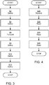
Fig. 3 and 4 are flowcharts of a transmission and a receiving method, respectively, according to embodiments. - The present invention will now be described more fully hereinafter with reference to the accompanying drawings, in which certain embodiments of the invention are shown. This invention may, however, be embodied in many different forms and should not be construed as limited to the embodiments set forth herein; rather, these embodiments are provided by way of example so that this disclosure will be thorough and complete, and will fully convey the scope of the invention to those skilled in the art. Like numbers refer to like elements throughout.
- New address formats for visible light communications applications that are more efficient for broadcast and multicast applications will now be described. The proposed address formats can advantageously be incorporated into the addressing scheme inherited from the existing IEEE 802.15.4 standard protocol by removal of some constraints and with new interpretations of at least some of the existing signaling.
- However, preferably all the existing features of the existing IEEE 802.15.4 standard protocol should be retained. The inventors of the present invention have discovered that there is enough space in the bits available in the frame control field to accommodate both the proposed features and the existing features. The inventors of the present invention have further discovered that the interpretation of some of the bits advantageously is modified to accommodate the new features while retaining backwards compatibility with the existing features. The proposed bit codings are preferably arranged in such a way that the proposed features are a natural consequence of the codings.
- Methods and devices for transmitting and/or receiving a message in an IEEE 802.15.4 based network will now be described with references to the lighting devices of
Fig. 1 , the IEEE 802.15.4 based network ofFig. 2 and the flowcharts ofFigs. 3 and 4 . The message comprises a sequence of ordered data portions which in turn comprises address fields and one or two frame control fields/octets.Fig. 1 schematically illustrates, in terms of functional blocks, alighting device lighting device lighting device 1a. A lighting device arranged to at least receive a message is denoted a receivinglighting device 1b.Fig. 2 schematically illustrates an IEEE 802.15.4 basednetwork 5 comprising a transmittinglighting device 1a transmitting message 6 to a receivinglighting device 1b. Thelighting device lighting device processing unit 2, atransmitter 3, and areceiver 4. Thetransmitter 3 may have a light emitter associated with the illumination function of thelight source processing unit 2. Thereceiver 4, which may have a light detector arranged to detect visible light communications, and thus to receive a message transmitted by visible light communications, is arranged to receive light emitted by at least one other lighting device and in the received light detect coded light. Thereceiver 4 may comprise a photosensor or photodetector or any other suitable sensor of light. For example, thereceiver 4 may comprise a charge-coupled device (CCD), CMOS sensor, a photodiode (inter alia a reverse biased LED), a phototransistor, a photoresistor, or the like. - According to the present invention a VAN device is enabled to send a broadcast to an entire VAN by using just the VAN ID as destination without the need to include the VAN broadcast address. There can be an optional source VAN address but, since the source VAN ID would be the same, it is preferably not transmitted. In general, the VAN is one example of a group G. It should be noted that the herein disclosed embodiments are, although described in a VAN context, also applicable for a general group of devices which not necessarily are part of a VAN. This structure achieves an extra bit of efficiency when broadcasting short messages. Making the source address optional provides anonymous transmission (whose purpose is mainly efficiency rather than a need to hide). Not transmitting a source address may be regarded as an efficiency issue within a VAN - the fact that a destination VAN has been specified means that it is not a true indiscriminate broadcast.
- In order to achieve this the interpretation of the VAN_ID_compression bit to mean that, when set, there will always be a destination VAN id transmitted and the source VAN ID shall be assumed to be identical and never transmitted. As such, it over-rides destination address modes 0 and 1 (which do not carry the VAN ID) and
source address modes 2 and 3 (which do carry the VAN ID). In a step S2 bits in a first subfield of the ordered data portions indicative of use of the address fields are therefore defined by theprocessing unit 2 of the transmittinglighting device 1a. Upon reception of amessage 6 comprising the first subfield theprocessing unit 2 of the receivinglighting device 1b reads bits in the subfield of the ordered data portions indicative of use of the address fields, step S22. - Because of the over-riding ability of the new VAN_ID_compression bit, certain combinations produce similar results (e.g., expressing the settings as a triplet: v-d-s, where v represents the VAN ID compression bit, d represents the Destination Addressing Mode and s represents the Source Addressing Mode. Some examples of usage are:
- 0-0-1 - Indiscriminate broadcast ('Shouter device'): Destination address not used (indicates to receiver that these broadcasts can be safely ignored), only long, such as 64-bit, source address used (receiver, RX, assumes VAN is not set and/or transmitter, TX, is not VAN capable)
- 0-1-1 - Global point-to-point: Destination address is long, such as a 64-bit, address of specific device. No grouping involved
- 0-2-1 - Global-to-local point-to-point: Destination address is a valid VAN ID and assigned middle length (16-bit) address within the VAN (Source address indicates source is not a member of any VAN)
- 0-2-1 - Global-to-local VAN broadcast: As above but middle length (16-bit) address takes special value of 0xFFFF to indicate that all VAN members should receive this message (RX is obliged to pass up such messages to the upper layers)
- 0-2-1 - Normal broadcast: Destination address and destination VAN field both take the special middle length (16-bit) setting of 0xFFFF (RX is obliged to pass up such messages to the upper layers)
- 0-2-2 - As for 0-2-1 except source is member of different VAN (VAN IDs are different)
- 1-2-2 - As for 0-2-2 except source is member of same VAN (VAN IDs are the same and source VAN is suppressed by VIC field)
- 1-2-1 - As for 0-2-1 but VIC field can signal change in RX interpretation. Does not change address field generation since destination VAN ID is already present and source VAN id already not present
- 1-0-1 - Indiscriminate broadcast to VAN: A way of broadcasting to a VAN that saves two bytes - VIC ensures presence of the necessary destination VAN ID, despite DAM of 0
- 1-0-2 - As above but sender is a member of the VAN
- 1-0-0 - Anonymous VAN broadcast - for those occasions when it does not matter which device that gave the command
- The similar results are due to two phenomena. Firstly, when VIC, VAN ID Compression, is set to one, it forces the destination VAN ID to be present and the source VAN ID to be suppressed. SAM and DAM can each be set to either 1 or 3 (long, such as a 64-bit, address, without/with VAN ID) with no change in the address fields. This allows extra information to be sent. Secondly, there are certain combinations of DAM (2 and 3) and SAM (0 and 1) that naturally produce a situation in which the destination VAN ID is present and the source VAN ID is not. The setting of VIC does not change this and could therefore be used to signal extra information to the receiver. The combinations listed may be grouped as follows: { 1-1-1, 1-1-3, 1-3-1, 1-3-3 } and { 0-2-0, 1-2-0 }, { 0-2-1, 1-2-1, 1-2-3*}, { 0-3-0, 1-3-0 }, { 0-3-1, 1-3-1, 1-3-3*}. The codes marked * take advantage of both phenomena and some codes appear in the list twice. Again, although this is a natural outcome of the coding scheme, it does make it possible for the transmitter to signal some extra information. For example, a setting of 1 or 3 as the source address with VIC set to 1, could inform the receiver whether the transmitter is able to take part in a closed group (or VAN) (3) or not (1). Many of the above variants use a DAM or SAM of 1, which is a reserved (i.e., invalid) value in the existing IEEE 802.15.4 standard protocol, and some use the VIC in ways not anticipated by 15.4, giving us the potential ability to guide the receiver in its interpretation.
- According to the existing IEEE 802.15.4 standard protocol, the only time an address mode of '0' is used is in the special case of an exchange of packets between a VAN hub (in the existing IEEE 802.15.4 terminology: a PAN coordinator) and a member of that same VAN. By allowing address mode '0' to be used more widely, support of anonymous transmission (i.e. that the source address is not present), indiscriminate broadcast (i.e. that the destination address is not present) and the combination thereof is allowed.
- According to the existing IEEE 802.15.4 standard protocol, address mode '1' is not supported. The two-bit address fields may according to the present invention be interpreted as containing one bit (bit 1) indicating the presence (1) or otherwise (0) of the address field and another bit (bit 0) indicating the type of address, short or long (according to the present non-limiting example 16 bit (0) or 64 bit (1)). According to this interpretation (and any implementation built around it), mode 1 and mode 0 both have bit 1 set to 0, meaning no address field, and are therefore equivalent in practice. In pseudocode, a procedure for receiving these bits may be written as:
 IF (bit_1 = 0)
 THEN no_address present
 ELSE IF (bit_0 = 0)
   THEN 16_bit_address_present AND VAN_ID_present
   ELSE 64_bit_address_present AND VAN_ID_present
 ENDIF
 ENDIF
 IF (bit_0 = 1)
 THEN 64_bit address present
 ENDIF
 IF (bit_1 = 1)
 THEN VAN_ID_present
 IF (bit_0 = 0)
   THEN 16_bit_address_present
 ENDIF
 ENDIF
| Octets: 2 | 1 | 0/2 | 0/2/8 | 0/2 | 0/2/8 | arb. |
| Frame Control | Sequence Number | Destination VAN Identifier | Destination Address | Source VAN Identifier | Source Address | Auxiliary Security Header |
| Addressing fields | ||||||
| MHR | ||||||
| Bits: 0-2 | 3 | 4 | 5 | 6 | 7-9 | 10-11 | 12-13 | 14-15 |
| Frame Type | Security Enabled | Frame Pending | Ack. Request | VAN ID compression | Reserved | Destination Addressing Mode | Frame Version | Source Addressing Mode |
- 0 if VAN ID and address are not present
- 2 if VAN ID and middle length (16-bit) address are present
- 3 if VAN ID and long (64-bit) address are present, and where
- 1 is an undefined value.
- v represents
bit 6, the VAN ID compression bit, - d represents bits 10-11, the destination addressing mode, and
- s represents the source addressing mode.
| Octets: 2 | 1 | 2 | 8 | 2 | 8 |
| 0-3-3 | 0x-- | 0xFFFF | 0x123456789ABCDEF0 | 0xFFFF | 0x0FEDCBA87654321 |
| Frame Control | Sequence Number | Destination VAN Identifier | Destination Address | Source VAN Identifier | Source Address |
| Addressing fields | |||||
| MHR | |||||
| Octets: 2 | 1 | 2 | 2/8 | 2 | 2/8 |
| 0-2-2 | 0x-- | 0x1234 | 0x5678 | 0x90AB | 0xDEF0 |
| 0-2-3 | 0x1234 | 0x5678 | 0x90AB/FFFF | 0x0FEDCBA87654321 | |
| 0-3-2 | 0x1234/FFFF | 0x123456789ABCDEF0 | 0x90AB | 0xDEF0 | |
| Frame Control | Sequence Number | Destination VAN Identifier | Destination Address | Source VAN Identifier | Source Address |
| Addressing fields | |||||
| MHR | |||||
| Octets: 2 | 1 | 2/0 | 2/0 | 0/2 | 0/2 |
| 0-2-0 | 0x-- | 0x1234 | 0x5678 | - | - |
| 0-0-2 | - | - | 0x1234 | 0xDEF0 | |
| Frame Control | Sequence Number | Destination VAN Identifier | Destination Address | Source VAN Identifier | Source Address |
| Addressing fields | |||||
| MHR | |||||
| Octets: 2 | 1 | 2/0 | 2/0 | 0/2 | 0/2 |
| 1-2-2 | 0x-- | 0x1234 | 0x5678 | - | 0xDEF0 |
| Frame Control | Sequence Number | Destination VAN Identifier | Destination Address | Source VAN Identifier | Source Address |
| Addressing fields | |||||
| MHR | |||||
| Octets: 2 | 1 | 2/0 | 8/0 | 0 | 8/0 |
| 1-3-3 | 0x-- | 0xFFFF | 0x123456789ABCDEF0 | - | 0x0FEDCBA987654321 |
| 0-3-0 | 0xFFFF | 0x123456789ABCDEF0 | - | - | |
| 0-0-0 | - | - | - | - | |
| 0-1?-3 | - | 0x123456789ABCDEF0 | - | 0x0FEDCBA987654321 | |
| Frame Control | Sequence Number | Destination VAN Identifier | Destination Address | Source VAN Identifier | Source Address |
| Addressing fields | |||||
| MHR | |||||
| Octets: 2 | 1 | 2 | 0 | 0 | 2/0 |
| 1?-0?-2 | 0x-- | 0x1234 | - | - | 0x0FED |
| 1?-0?-0 | 0x1234 | - | - | - | |
| Frame Control | Sequence Number | Destination VAN Identifier | Destination Address | Source VAN Identifier | Source Address |
| Addressing fields | |||||
| MHR | |||||
| Octets: 1/2 | 0/1 | 0/2 | 0/2/8 | 0/2 | 0/2/8 | arb. |
| Frame Control | Sequence Number | Destination VAN Identifier | Destination Address | Source VAN Identifier | Source Address | Auxiliary Security Header |
| Addressing fields | ||||||
| MHR | ||||||
| Bits: b0b1 | Description |
| 00 | Frame compatible with the CL standard, single Frame Control field/octet |
| 10 | Reserved |
| 01 | Reserved |
| 11 | Frame compatible with the CL standard, two Frame Control fields/octets |
| Bits: 8-9 | 10 | 11 | 12-13 | 14-15 |
| Frame Type | Security Enabled | Frame Pending | ACK Request; Sequence Number Present | Reserved |
| Bits b12 b13 | Description |
| 00 | No ACK requested, no sequence number |
| 10 | Reserved |
| 01 | No ACK requested, sequence number present |
| 11 | ACK requested, sequence number present |
Claims (12)
- A method for transmitting a message (6) in a network (5) by means of visible light communication based on the medium access control, MAC, layer of IEEE 802.15.4 standard, the message comprising a sequence of ordered data portions, wherein said sequence of ordered data portions comprises a MAC header, wherein the MAC header comprises address fields, at least a first frame control field, and wherein said first frame control field at least comprises a first subfield and a second subfield, the method comprising:defining (S2) bits in the first subfield of the first frame control field indicative of use of said address fields anddefining (S4) bits in the second subfield of the first frame control field indicative of whether a second frame control field is present in said MAC header; andtransmitting (S6) said message comprising said first frame control field and depending on said defined bits in said second subfield of the first frame control field, said second frame control field.
- The method according to claim 1, wherein said bits of said first subfield are further indicative of destination address not being present in said MAC header.
- The method according to claim 1, wherein said bits of said first subfield are further indicative of source address not being present in said MAC header.
- The method according to claim 1, wherein said first subfield has a first sub-subfield which represents group identifier compression, and wherein said first sub-subfield has one bit, the method further comprising:
defining (S8) said one bit of said first sub-subfield to decimal value '1' with meaning presence of destination group identifier, whereby the source group identifier is not transmitted and is equal to the destination group identifier. - The method according to claim 1, wherein said first subfield has a second sub-subfield which represents destination addressing mode, DAM.
- The method according to claim 5, the method further comprising:
defining (S10) bits of said second sub-subfield with meaning group identifier is not present and destination address is long, preferably eight bytes. - The method according to claim 1, wherein said first subfield has a third sub-subfield which represents source addressing mode, SAM.
- The method according to claim 7, the method further comprising:
defining (S12) bits of said third sub-subfield with meaning group identifier is not present and source address is long, preferably eight bytes. - The method according to claim 1, wherein said second subfield has a first sub-subfield which represents frame version and wherein said bits indicative of whether one or two frame control fields is/are present in said ordered data portions are part of said first sub-subfield.
- A method for receiving a message (6) in a network (5) by means of visible light communication based on the medium access control, MAC, layer of IEEE 802.15.4 standard, the message comprising a sequence of ordered data portions, wherein said sequence of ordered data portions comprises a MAC header, wherein the MAC header comprises address fields, at least a first frame control field, and wherein said first frame control field at least comprises a first subfield and a second subfield,, the method comprising:receiving (S20) the message;reading (S22) bits in a first subfield of the first frame control field indicative of use of said address fields; andreading (S24) bits in a second subfield of the first frame control field indicative of whether a second frame control field is present in said MAC header; andreading (S26) said first frame control field and depending on said bits in said second subfield of the first frame control field, said second frame control field.
- A transmitting lighting device (la) for transmitting a message (6) in a network (5) by means of visible light communication based on the medium access control, MAC, layer of IEEE 802.15.4 standard, the message comprising a sequence of ordered data portions, wherein said sequence of ordered data portions comprises a MAC header, wherein the MAC header comprises address fields, at least a first frame control field, and wherein said first frame control field at least comprises a first subfield and a second subfield, the lighting device comprising:a processing unit (2) arranged to define bits in a first subfield of the first frame control field indicative of use of said address fields; and arranged to define bits in a second subfield of the first frame control field indicative of whether a second frame control field is present in said MAC header; anda transmitter (3) arranged to transmit said message comprising said first frame control field and depending on said defined bits in said second subfield of the first frame control field, said second frame control field.
- A receiving lighting device (1b) for receiving a message (6) in a network (5) by means of visible light communication based on the medium access control, MAC, layer of IEEE 802.15.4 standard, the message comprising a sequence of ordered data portions, wherein said sequence of ordered data portions comprises a MAC header, wherein the MAC header comprises address fields, at least a first frame control field, and wherein said first frame control field at least comprises a first subfield and a second subfield, the lighting device comprising:a receiver (4) arranged to receive the message;a processing unit (2) arranged to read bits in the first subfield of the first frame control field indicative of use of said address fields; and arranged to read bits in a second subfield of the first frame control field indicative of whether a second frame control field is present in said MAC header; and arranged to read said first frame control field and depending on said bits in said second subfield of the first frame control field, said second frame control field.
Applications Claiming Priority (2)
| Application Number | Priority Date | Filing Date | Title |
|---|---|---|---|
| US201161579751P | 2011-12-23 | 2011-12-23 | |
| PCT/IB2012/057233 WO2013093721A1 (en) | 2011-12-23 | 2012-12-12 | Protocols for visible light communications |
Publications (2)
| Publication Number | Publication Date |
|---|---|
| EP2749005A1 EP2749005A1 (en) | 2014-07-02 |
| EP2749005B1 true EP2749005B1 (en) | 2020-06-24 |
Family
ID=47603884
Family Applications (1)
| Application Number | Title | Priority Date | Filing Date |
|---|---|---|---|
| EP12818821.6A Active EP2749005B1 (en) | 2011-12-23 | 2012-12-12 | Protocols for visible light communications |
Country Status (6)
| Country | Link |
|---|---|
| US (1) | US9871585B2 (en) |
| EP (1) | EP2749005B1 (en) |
| JP (1) | JP6138821B2 (en) |
| CN (1) | CN103999432B (en) |
| IN (1) | IN2014CN05011A (en) |
| WO (1) | WO2013093721A1 (en) |
Families Citing this family (10)
| Publication number | Priority date | Publication date | Assignee | Title |
|---|---|---|---|---|
| JP6704899B2 (en) * | 2014-08-01 | 2020-06-03 | シグニファイ ホールディング ビー ヴィSignify Holding B.V. | Lighting fixture with wireless module |
| CN104506235B (en) * | 2014-12-10 | 2018-11-30 | 北京智谷睿拓技术服务有限公司 | Optical communication method and equipment |
| CN104618018B (en) * | 2014-12-30 | 2018-09-18 | 北京智谷睿拓技术服务有限公司 | Data transmission method based on visible light communication and device |
| CN105959061A (en) * | 2016-06-21 | 2016-09-21 | 江苏大学 | LED-to-LED half-duplex communication system |
| CN107707302A (en) * | 2016-08-08 | 2018-02-16 | 镇江明辉光信息科技有限公司 | LED-based closely point-to-point high speed and bidirectional data transfers system |
| CN106982094A (en) * | 2017-04-09 | 2017-07-25 | 深圳市先通网信息科技有限公司 | Visible light communication method and system |
| US11328564B2 (en) | 2019-08-31 | 2022-05-10 | Appleton Grp Llc | Event indications of hazardous environment luminaires using visual sequences |
| US11232684B2 (en) | 2019-09-09 | 2022-01-25 | Appleton Grp Llc | Smart luminaire group control using intragroup communication |
| US11219112B2 (en) | 2019-09-09 | 2022-01-04 | Appleton Grp Llc | Connected controls infrastructure |
| US11343898B2 (en) | 2019-09-20 | 2022-05-24 | Appleton Grp Llc | Smart dimming and sensor failure detection as part of built in daylight harvesting inside the luminaire |
Family Cites Families (7)
| Publication number | Priority date | Publication date | Assignee | Title |
|---|---|---|---|---|
| JP4508915B2 (en) * | 2005-03-23 | 2010-07-21 | 京セラ株式会社 | Optical transmitter and visible light communication system |
| JP4643403B2 (en) * | 2005-09-13 | 2011-03-02 | 株式会社東芝 | Visible light communication system and method |
| US8098689B2 (en) * | 2006-05-11 | 2012-01-17 | Intel Corporation | Systems and methods for frame tunnelling in wireless communications |
| DE102006037243B4 (en) * | 2006-08-09 | 2010-06-02 | Siemens Ag | Network for the wireless transmission of data |
| KR101009803B1 (en) * | 2008-02-21 | 2011-01-19 | 삼성전자주식회사 | Method and apparatus for transmitting/receiving data using a visible light communication |
| EP2334017B1 (en) * | 2009-12-10 | 2018-01-03 | Alcatel Lucent | Forwarding a packet in a sensor personal area network |
| KR101951358B1 (en) * | 2011-12-15 | 2019-02-22 | 삼성전자주식회사 | Wireless power transmitter, wireless power receiver and method for controlling each thereof |
-
2012
- 2012-12-12 JP JP2014548278A patent/JP6138821B2/en not_active Expired - Fee Related
- 2012-12-12 IN IN5011CHN2014 patent/IN2014CN05011A/en unknown
- 2012-12-12 US US14/368,063 patent/US9871585B2/en not_active Expired - Fee Related
- 2012-12-12 EP EP12818821.6A patent/EP2749005B1/en active Active
- 2012-12-12 CN CN201280063867.0A patent/CN103999432B/en not_active Expired - Fee Related
- 2012-12-12 WO PCT/IB2012/057233 patent/WO2013093721A1/en unknown
Non-Patent Citations (1)
| Title |
|---|
| None * |
Also Published As
| Publication number | Publication date |
|---|---|
| CN103999432A (en) | 2014-08-20 |
| JP6138821B2 (en) | 2017-05-31 |
| WO2013093721A1 (en) | 2013-06-27 |
| US20150071644A1 (en) | 2015-03-12 |
| US9871585B2 (en) | 2018-01-16 |
| CN103999432B (en) | 2017-07-14 |
| EP2749005A1 (en) | 2014-07-02 |
| JP2015506602A (en) | 2015-03-02 |
| IN2014CN05011A (en) | 2015-09-18 |
Similar Documents
| Publication | Publication Date | Title |
|---|---|---|
| EP2749005B1 (en) | Protocols for visible light communications | |
| US8452188B2 (en) | Visible light communication method and system | |
| AU2009200917B2 (en) | Radio network communication system and protocol | |
| JP4862050B2 (en) | Initial connection establishment in a wireless communication system | |
| US7013157B1 (en) | Method for multicast delivery with designated acknowledgment | |
| US8380082B2 (en) | Method and apparatus for outputting visibility frame in visible light communication system providing multiple communication modes | |
| CA2562048C (en) | Wireless communication protocol | |
| JP4719748B2 (en) | System and method for dynamic adaptation of transmission power and data rate by beaconing protocol | |
| JP2009522893A (en) | Initial connection establishment in a wireless communication system | |
| JP5645917B2 (en) | Acknowledgment transfer and reception method in wireless communication system | |
| CA2457232A1 (en) | Method and apparatus for controlling transmission of packets in a wireless communication system | |
| CN106470458B (en) | Method and device for controlling in WiFi network | |
| Wang et al. | Intra-frame bidirectional transmission in networks of visible LEDs | |
| JP6143774B2 (en) | Protocol for coded optical communication | |
| KR20120075184A (en) | Method and apparatus using heterogeneous protocols | |
| JP5981461B2 (en) | Method and apparatus for resolving temporary block flow | |
| US20040148426A1 (en) | Bluetooth broadcasting method | |
| CN111193544B (en) | Communication method and system based on visible light bidirectional communication system | |
| JP2018527858A (en) | Wireless communication method and system | |
| US20140199071A1 (en) | Method of processing dmx-vlc address using dmx-512 network and device using the same | |
| KR20090092038A (en) | Method and apparatus for transmitting data in wireless local area network using visible light communication |
Legal Events
| Date | Code | Title | Description |
|---|---|---|---|
| PUAI | Public reference made under article 153(3) epc to a published international application that has entered the european phase |
Free format text: ORIGINAL CODE: 0009012 |
|
| 17P | Request for examination filed |
Effective date: 20140327 |
|
| AK | Designated contracting states |
Kind code of ref document: A1 Designated state(s): AL AT BE BG CH CY CZ DE DK EE ES FI FR GB GR HR HU IE IS IT LI LT LU LV MC MK MT NL NO PL PT RO RS SE SI SK SM TR |
|
| DAX | Request for extension of the european patent (deleted) | ||
| RAP1 | Party data changed (applicant data changed or rights of an application transferred) |
Owner name: PHILIPS LIGHTING HOLDING B.V. |
|
| RAP1 | Party data changed (applicant data changed or rights of an application transferred) |
Owner name: PHILIPS LIGHTING HOLDING B.V. |
|
| RAP1 | Party data changed (applicant data changed or rights of an application transferred) |
Owner name: SIGNIFY HOLDING B.V. |
|
| STAA | Information on the status of an ep patent application or granted ep patent |
Free format text: STATUS: EXAMINATION IS IN PROGRESS |
|
| 17Q | First examination report despatched |
Effective date: 20190515 |
|
| GRAP | Despatch of communication of intention to grant a patent |
Free format text: ORIGINAL CODE: EPIDOSNIGR1 |
|
| STAA | Information on the status of an ep patent application or granted ep patent |
Free format text: STATUS: GRANT OF PATENT IS INTENDED |
|
| INTG | Intention to grant announced |
Effective date: 20200121 |
|
| GRAS | Grant fee paid |
Free format text: ORIGINAL CODE: EPIDOSNIGR3 |
|
| GRAA | (expected) grant |
Free format text: ORIGINAL CODE: 0009210 |
|
| STAA | Information on the status of an ep patent application or granted ep patent |
Free format text: STATUS: THE PATENT HAS BEEN GRANTED |
|
| AK | Designated contracting states |
Kind code of ref document: B1 Designated state(s): AL AT BE BG CH CY CZ DE DK EE ES FI FR GB GR HR HU IE IS IT LI LT LU LV MC MK MT NL NO PL PT RO RS SE SI SK SM TR |
|
| REG | Reference to a national code |
Ref country code: GB Ref legal event code: FG4D |
|
| REG | Reference to a national code |
Ref country code: CH Ref legal event code: EP |
|
| REG | Reference to a national code |
Ref country code: AT Ref legal event code: REF Ref document number: 1285028 Country of ref document: AT Kind code of ref document: T Effective date: 20200715 |
|
| REG | Reference to a national code |
Ref country code: DE Ref legal event code: R096 Ref document number: 602012070917 Country of ref document: DE |
|
| REG | Reference to a national code |
Ref country code: IE Ref legal event code: FG4D |
|
| PG25 | Lapsed in a contracting state [announced via postgrant information from national office to epo] |
Ref country code: SE Free format text: LAPSE BECAUSE OF FAILURE TO SUBMIT A TRANSLATION OF THE DESCRIPTION OR TO PAY THE FEE WITHIN THE PRESCRIBED TIME-LIMIT Effective date: 20200624 Ref country code: FI Free format text: LAPSE BECAUSE OF FAILURE TO SUBMIT A TRANSLATION OF THE DESCRIPTION OR TO PAY THE FEE WITHIN THE PRESCRIBED TIME-LIMIT Effective date: 20200624 Ref country code: NO Free format text: LAPSE BECAUSE OF FAILURE TO SUBMIT A TRANSLATION OF THE DESCRIPTION OR TO PAY THE FEE WITHIN THE PRESCRIBED TIME-LIMIT Effective date: 20200924 Ref country code: GR Free format text: LAPSE BECAUSE OF FAILURE TO SUBMIT A TRANSLATION OF THE DESCRIPTION OR TO PAY THE FEE WITHIN THE PRESCRIBED TIME-LIMIT Effective date: 20200925 Ref country code: LT Free format text: LAPSE BECAUSE OF FAILURE TO SUBMIT A TRANSLATION OF THE DESCRIPTION OR TO PAY THE FEE WITHIN THE PRESCRIBED TIME-LIMIT Effective date: 20200624 |
|
| REG | Reference to a national code |
Ref country code: LT Ref legal event code: MG4D |
|
| PG25 | Lapsed in a contracting state [announced via postgrant information from national office to epo] |
Ref country code: LV Free format text: LAPSE BECAUSE OF FAILURE TO SUBMIT A TRANSLATION OF THE DESCRIPTION OR TO PAY THE FEE WITHIN THE PRESCRIBED TIME-LIMIT Effective date: 20200624 Ref country code: BG Free format text: LAPSE BECAUSE OF FAILURE TO SUBMIT A TRANSLATION OF THE DESCRIPTION OR TO PAY THE FEE WITHIN THE PRESCRIBED TIME-LIMIT Effective date: 20200924 Ref country code: HR Free format text: LAPSE BECAUSE OF FAILURE TO SUBMIT A TRANSLATION OF THE DESCRIPTION OR TO PAY THE FEE WITHIN THE PRESCRIBED TIME-LIMIT Effective date: 20200624 Ref country code: RS Free format text: LAPSE BECAUSE OF FAILURE TO SUBMIT A TRANSLATION OF THE DESCRIPTION OR TO PAY THE FEE WITHIN THE PRESCRIBED TIME-LIMIT Effective date: 20200624 |
|
| REG | Reference to a national code |
Ref country code: NL Ref legal event code: MP Effective date: 20200624 |
|
| REG | Reference to a national code |
Ref country code: AT Ref legal event code: MK05 Ref document number: 1285028 Country of ref document: AT Kind code of ref document: T Effective date: 20200624 |
|
| PG25 | Lapsed in a contracting state [announced via postgrant information from national office to epo] |
Ref country code: NL Free format text: LAPSE BECAUSE OF FAILURE TO SUBMIT A TRANSLATION OF THE DESCRIPTION OR TO PAY THE FEE WITHIN THE PRESCRIBED TIME-LIMIT Effective date: 20200624 Ref country code: AL Free format text: LAPSE BECAUSE OF FAILURE TO SUBMIT A TRANSLATION OF THE DESCRIPTION OR TO PAY THE FEE WITHIN THE PRESCRIBED TIME-LIMIT Effective date: 20200624 |
|
| PG25 | Lapsed in a contracting state [announced via postgrant information from national office to epo] |
Ref country code: AT Free format text: LAPSE BECAUSE OF FAILURE TO SUBMIT A TRANSLATION OF THE DESCRIPTION OR TO PAY THE FEE WITHIN THE PRESCRIBED TIME-LIMIT Effective date: 20200624 Ref country code: PT Free format text: LAPSE BECAUSE OF FAILURE TO SUBMIT A TRANSLATION OF THE DESCRIPTION OR TO PAY THE FEE WITHIN THE PRESCRIBED TIME-LIMIT Effective date: 20201026 Ref country code: ES Free format text: LAPSE BECAUSE OF FAILURE TO SUBMIT A TRANSLATION OF THE DESCRIPTION OR TO PAY THE FEE WITHIN THE PRESCRIBED TIME-LIMIT Effective date: 20200624 Ref country code: RO Free format text: LAPSE BECAUSE OF FAILURE TO SUBMIT A TRANSLATION OF THE DESCRIPTION OR TO PAY THE FEE WITHIN THE PRESCRIBED TIME-LIMIT Effective date: 20200624 Ref country code: CZ Free format text: LAPSE BECAUSE OF FAILURE TO SUBMIT A TRANSLATION OF THE DESCRIPTION OR TO PAY THE FEE WITHIN THE PRESCRIBED TIME-LIMIT Effective date: 20200624 Ref country code: EE Free format text: LAPSE BECAUSE OF FAILURE TO SUBMIT A TRANSLATION OF THE DESCRIPTION OR TO PAY THE FEE WITHIN THE PRESCRIBED TIME-LIMIT Effective date: 20200624 Ref country code: IT Free format text: LAPSE BECAUSE OF FAILURE TO SUBMIT A TRANSLATION OF THE DESCRIPTION OR TO PAY THE FEE WITHIN THE PRESCRIBED TIME-LIMIT Effective date: 20200624 Ref country code: SM Free format text: LAPSE BECAUSE OF FAILURE TO SUBMIT A TRANSLATION OF THE DESCRIPTION OR TO PAY THE FEE WITHIN THE PRESCRIBED TIME-LIMIT Effective date: 20200624 |
|
| PG25 | Lapsed in a contracting state [announced via postgrant information from national office to epo] |
Ref country code: IS Free format text: LAPSE BECAUSE OF FAILURE TO SUBMIT A TRANSLATION OF THE DESCRIPTION OR TO PAY THE FEE WITHIN THE PRESCRIBED TIME-LIMIT Effective date: 20201024 Ref country code: PL Free format text: LAPSE BECAUSE OF FAILURE TO SUBMIT A TRANSLATION OF THE DESCRIPTION OR TO PAY THE FEE WITHIN THE PRESCRIBED TIME-LIMIT Effective date: 20200624 Ref country code: SK Free format text: LAPSE BECAUSE OF FAILURE TO SUBMIT A TRANSLATION OF THE DESCRIPTION OR TO PAY THE FEE WITHIN THE PRESCRIBED TIME-LIMIT Effective date: 20200624 |
|
| REG | Reference to a national code |
Ref country code: DE Ref legal event code: R097 Ref document number: 602012070917 Country of ref document: DE |
|
| PG25 | Lapsed in a contracting state [announced via postgrant information from national office to epo] |
Ref country code: DK Free format text: LAPSE BECAUSE OF FAILURE TO SUBMIT A TRANSLATION OF THE DESCRIPTION OR TO PAY THE FEE WITHIN THE PRESCRIBED TIME-LIMIT Effective date: 20200624 |
|
| PLBE | No opposition filed within time limit |
Free format text: ORIGINAL CODE: 0009261 |
|
| STAA | Information on the status of an ep patent application or granted ep patent |
Free format text: STATUS: NO OPPOSITION FILED WITHIN TIME LIMIT |
|
| 26N | No opposition filed |
Effective date: 20210325 |
|
| REG | Reference to a national code |
Ref country code: DE Ref legal event code: R119 Ref document number: 602012070917 Country of ref document: DE |
|
| REG | Reference to a national code |
Ref country code: CH Ref legal event code: PL |
|
| GBPC | Gb: european patent ceased through non-payment of renewal fee |
Effective date: 20201212 |
|
| PG25 | Lapsed in a contracting state [announced via postgrant information from national office to epo] |
Ref country code: SI Free format text: LAPSE BECAUSE OF FAILURE TO SUBMIT A TRANSLATION OF THE DESCRIPTION OR TO PAY THE FEE WITHIN THE PRESCRIBED TIME-LIMIT Effective date: 20200624 Ref country code: MC Free format text: LAPSE BECAUSE OF FAILURE TO SUBMIT A TRANSLATION OF THE DESCRIPTION OR TO PAY THE FEE WITHIN THE PRESCRIBED TIME-LIMIT Effective date: 20200624 |
|
| REG | Reference to a national code |
Ref country code: BE Ref legal event code: MM Effective date: 20201231 |
|
| PG25 | Lapsed in a contracting state [announced via postgrant information from national office to epo] |
Ref country code: IE Free format text: LAPSE BECAUSE OF NON-PAYMENT OF DUE FEES Effective date: 20201212 Ref country code: LU Free format text: LAPSE BECAUSE OF NON-PAYMENT OF DUE FEES Effective date: 20201212 Ref country code: FR Free format text: LAPSE BECAUSE OF NON-PAYMENT OF DUE FEES Effective date: 20201231 |
|
| PG25 | Lapsed in a contracting state [announced via postgrant information from national office to epo] |
Ref country code: DE Free format text: LAPSE BECAUSE OF NON-PAYMENT OF DUE FEES Effective date: 20210701 Ref country code: CH Free format text: LAPSE BECAUSE OF NON-PAYMENT OF DUE FEES Effective date: 20201231 Ref country code: GB Free format text: LAPSE BECAUSE OF NON-PAYMENT OF DUE FEES Effective date: 20201212 Ref country code: LI Free format text: LAPSE BECAUSE OF NON-PAYMENT OF DUE FEES Effective date: 20201231 |
|
| PG25 | Lapsed in a contracting state [announced via postgrant information from national office to epo] |
Ref country code: IS Free format text: LAPSE BECAUSE OF FAILURE TO SUBMIT A TRANSLATION OF THE DESCRIPTION OR TO PAY THE FEE WITHIN THE PRESCRIBED TIME-LIMIT Effective date: 20201024 Ref country code: TR Free format text: LAPSE BECAUSE OF FAILURE TO SUBMIT A TRANSLATION OF THE DESCRIPTION OR TO PAY THE FEE WITHIN THE PRESCRIBED TIME-LIMIT Effective date: 20200624 Ref country code: MT Free format text: LAPSE BECAUSE OF FAILURE TO SUBMIT A TRANSLATION OF THE DESCRIPTION OR TO PAY THE FEE WITHIN THE PRESCRIBED TIME-LIMIT Effective date: 20200624 Ref country code: CY Free format text: LAPSE BECAUSE OF FAILURE TO SUBMIT A TRANSLATION OF THE DESCRIPTION OR TO PAY THE FEE WITHIN THE PRESCRIBED TIME-LIMIT Effective date: 20200624 |
|
| PG25 | Lapsed in a contracting state [announced via postgrant information from national office to epo] |
Ref country code: MK Free format text: LAPSE BECAUSE OF FAILURE TO SUBMIT A TRANSLATION OF THE DESCRIPTION OR TO PAY THE FEE WITHIN THE PRESCRIBED TIME-LIMIT Effective date: 20200624 |
|
| PG25 | Lapsed in a contracting state [announced via postgrant information from national office to epo] |
Ref country code: BE Free format text: LAPSE BECAUSE OF NON-PAYMENT OF DUE FEES Effective date: 20201231 |