EP2748981B1 - Séparation d'environnement de réseau - Google Patents
Séparation d'environnement de réseau Download PDFInfo
- Publication number
- EP2748981B1 EP2748981B1 EP12768907.3A EP12768907A EP2748981B1 EP 2748981 B1 EP2748981 B1 EP 2748981B1 EP 12768907 A EP12768907 A EP 12768907A EP 2748981 B1 EP2748981 B1 EP 2748981B1
- Authority
- EP
- European Patent Office
- Prior art keywords
- network
- data packet
- separation module
- network device
- tag
- Prior art date
- Legal status (The legal status is an assumption and is not a legal conclusion. Google has not performed a legal analysis and makes no representation as to the accuracy of the status listed.)
- Not-in-force
Links
Images


Classifications
-
- H—ELECTRICITY
- H04—ELECTRIC COMMUNICATION TECHNIQUE
- H04L—TRANSMISSION OF DIGITAL INFORMATION, e.g. TELEGRAPHIC COMMUNICATION
- H04L63/00—Network architectures or network communication protocols for network security
- H04L63/02—Network architectures or network communication protocols for network security for separating internal from external traffic, e.g. firewalls
- H04L63/0227—Filtering policies
- H04L63/0245—Filtering by information in the payload
-
- H—ELECTRICITY
- H04—ELECTRIC COMMUNICATION TECHNIQUE
- H04L—TRANSMISSION OF DIGITAL INFORMATION, e.g. TELEGRAPHIC COMMUNICATION
- H04L12/00—Data switching networks
- H04L12/28—Data switching networks characterised by path configuration, e.g. LAN [Local Area Networks] or WAN [Wide Area Networks]
- H04L12/46—Interconnection of networks
- H04L12/4641—Virtual LANs, VLANs, e.g. virtual private networks [VPN]
-
- H—ELECTRICITY
- H04—ELECTRIC COMMUNICATION TECHNIQUE
- H04L—TRANSMISSION OF DIGITAL INFORMATION, e.g. TELEGRAPHIC COMMUNICATION
- H04L63/00—Network architectures or network communication protocols for network security
- H04L63/02—Network architectures or network communication protocols for network security for separating internal from external traffic, e.g. firewalls
- H04L63/0209—Architectural arrangements, e.g. perimeter networks or demilitarized zones
Definitions
- This invention relates to the field of information security and more particularly to the field of network environment separation.
- US2003/0120763 A1 discloses a mechanism for segregating traffic amongst STAs that are associated with a bridge is based upon the use of a VLAN to segregate traffic.
- WO 02/079949 A2 relates to a method and an apparatus, implementing and using techniques for processing a data packet in a packet forwarding device.
- a data packet is received.
- a virtual local area network destination is determined for the received data packet, and a set of rules associated with the virtual local area network destination is identified. The rules are applied to the data packet.
- US 2002/091795 A1 relates to a method and a system in which data packets from multiple customer VLANs are forwarded over a MAN using VLAN aggregation.
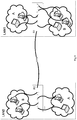
- Fig. 1 which shows two Local Area Networks LAN1 and LAN2 (LAN- local area network) that are connected over an encrypted Virtual Private Network (VPN) tunnel, established by two access routers ( R1 and R2 ) .
- LAN1 and LAN2 can represent, for example, local area networks of the same organization, which are located at different locations on the globe.
- routers R1 and R2 on either sides of the network are connected each to a number of nodes.
- the nodes in LAN1 and LAN2 are divided into departments, department A (e.g. engineering) and department B (e.g. accounting).
- the nodes which are assigned to department A in both LAN1 and LAN2 constitute a first network environment and the nodes which are assigned to department B in both LAN1 and LAN2 constitute a second network environment.
- IEEE Std 802.1QTM-2005 IEEE Std 802.1Q-1998
- IEEE Std 802.1uTM-2001 IEEE Std 802.1vTM-2001
- IEEE Std 802.1sTM-2002 IEEE Standard for Local and metropolitan area networks Virtual Bridged Local Area Networks: IEEE Std 802.1QTM-2005, IEEE Std 802.1Q-1998, IEEE Std 802.1uTM-2001,IEEE Std 802.1vTM-2001, and IEEE Std 802.1sTM-2002.
- the phrase “for example,” “such as”, “for instance” and variants thereof describe non-limiting embodiments of the presently disclosed subject matter.
- Reference in the specification to “one case”, “some cases”, “other cases” or variants thereof means that a particular feature, structure or characteristic described in connection with the embodiment(s) is included in at least one embodiment of the presently disclosed subject matter.
- the appearance of the phrase “one case”, “some cases”, “other cases” or variants thereof does not necessarily refer to the same embodiment(s).
- fewer, more and/or different stages than those shown in Fig . 5 , Fig. 7 , Fig. 9 and Fig. 11 may be executed.
- one or more stages illustrated in Fig . 5 , Fig. 7 , Fig. 9 and Fig. 11 may be executed in a different order and/or one or more groups of stages may be executed simultaneously.
- Fig 2 , Fig. 3 , Fig. 4 , Fig. 6 , Fig. 8 and Fig. 10 illustrate a general schematic of the system and/or network architecture in accordance with an embodiment of the presently disclosed subject matter. Modules in Fig 2 , Fig. 3 , Fig. 4 , Fig.
- Fig. 6 , Fig. 8 and Fig. 10 can be made up of any combination of software, hardware and/or firmware that performs the functions as defined and explained herein.
- the modules in Fig 2 , Fig. 3 , Fig. 4 , Fig. 6 , Fig. 8 , and Fig. 10 may be centralized in one location or dispersed over more than one location.
- the system may comprise fewer, more, and/or different modules than those shown in Fig 2 , Fig. 3 , Fig. 4 , Fig. 6 , Fig. 8 , and Fig. 10 .
- the teachings of the presently disclosed subject matter includes a secure network separation module which can be incorporated within a network device and which can control transmission of data between different network environments.
- the secure network separation module disclosed herein is adapted to enable the validation of data packets which are transmitted between different nodes and thereby restrict the unauthorized transmission of data packets between different network environments.
- the secure network separation module (or in short “separation module”) of the presently disclosed subject matter can be incorporated as part of network devices (such as switches, routers, media converters, advanced telecommunication cards (ATC), etc.) and be configured as a designated programmable module which is write-protected and can be accessed and altered in a secured manner, only by authorized personnel and with special equipment. Particularly, it is configured to be protected from modification of its preprogrammed parameters by remote access via the associated network.
- network devices such as switches, routers, media converters, advanced telecommunication cards (ATC), etc.
- a separation module can be manufactured as a write protected memory device such as a one-time programmable non-volatile memory (OTP NVM) with a high-speed programmable logic (depending on the SFP bandwidth).
- a separation module can be a reprogrammable memory device which applies a stringent write-protection mechanism, for example a programmable FPGA that only accepts an encrypted binary with a pre-loaded (and burnt) key.
- the separation module can be incorporated within a small form-factor pluggable (SFP) transceiver to create a secure SFP.
- SFP small form-factor pluggable
- an SFP can be plugged into a standard SFP-enabled network device, and used to interface the network device with a fiber optic or copper networking cable to facilitate communication between different nodes in a network.
- the secure SFP disclosed herein is adapted to facilitate the functionality of the separation module and enable the validation of data packets which are transmitted between different nodes and thereby restrict the unauthorized transmission of data packets between different network environments.
- the secure SFP can maintain the core structure of previously known SFPs and is therefore compatible with existing network infrastructure equipment.
- a secure SFP is a non-limiting example and the presently disclosed subject matter contemplates other implementations of a separation module, for example, in a printed circuit board which can be integrated as part of the network device's motherboard.
- Fig. 2 is a block diagram schematically illustrating a router and a secure SFP transceiver, in accordance with the presently disclosed subject matter.
- Fig. 2 shows router 202 comprising a switching fabric 204 adapted to interconnect and enable data transmission between plurality of secure SFPs ( 206 1 -n ), which are connected to router 202.
- Fig. 2 also shows a detailed view of one secure SFP 210.
- Secure SFP 210 comprises a physical interface 212 for physically connecting with an input cable and receiving incoming communication. Physical interface is connected to Phy 214 which can be configured for example to perform analog to digital and digital to analog conversion of incoming and outgoing communication signals, respectively.
- SFP 210 further comprises a network environment separation module 216 (or in short “separation module”) which is configured to control data transmission through SFP 210.
- separation module 216 is preprogrammed with a "network-id” that identifies secure SFP 210 and assigns it to a certain network environment.
- Separation module 216 is configured to receive data packets sent by a node to router 202 (uplinked data packets which are sent in the direction of the switching fabric) and based on its respectivenetwork-id, tag the data packet in order to indicate the respective network environment of the node. Separation module 216 is further configured to receive data packets transmitted in the opposite direction i.e. from router 202 (down-linked data packets which are sent away from the switching fabric) and validate, again based on it respective network-id, that the data packets are being transmitted between nodes that are assigned to the same network environment.
- separation module 216 within secure SFP 210 may vary, for example in case secure SFP 210 comprises a network interface card (NIC) for storing a MAC address, separation module 216 can be located before or after the NIC card. However, in order to enable to control the transmission of data to the switching fabric, separation module 216 is located before the switching fabric.
- NIC network interface card
- Fig. 3 is a functional block diagram schematically illustrating a network environment separation module, in accordance with the presently disclosed subject matter.
- network environment separation module 216 comprises a tagging module 301, a validation module 303 and a stripping module 305.
- Separation module 216 can also comprise a non-volatile computer memory 309 for storing its network-id.
- separation module 216 can further comprise a direction determination module 307.
- different modules described herein with reference to separation module 216 can be distributed into separate units.
- tagging module 301 can be configured in one unit and validation module 303 and stripping module 305 can be configured in a second unit.
- Separation module 216 can be associated with a processor (e.g. located in SFP 210 ) to obtain processing capabilities.
- a processor e.g. located in SFP 210
- Fig. 4 is a functional block diagram schematically illustrating network architecture in accordance with the presently disclosed subject matter.
- the network architecture which is illustrated comprises a single router R3 connected to a plurality of nodes (e.g. computer terminals, computer servers, computer facilities such as printers or fax machines, etc.).
- the nodes which are connected to router R3 are assigned to different groups (denoted by the letters A, B and C ) each group constituting a different network environment.
- each group of nodes can correspond, for example, to a different department in the same organization.
- each node is connected to a respective secure SFP port in router R3.
- part or all of the nodes assigned to the same group can first be connected to one or more intermediate routers which in turn can be connected to router R3.
- router R3 instead of a single router (router R3 ) as disclosed in Fig. 4 , multiple interconnected routers can be used.
- Router R3 is configured in accordance with the teachings of the presently disclosed subject matter to obtain network environment separation and avoid data transfer between nodes which are assigned to different groups.
- Secure SFP ports (s SFP 1-8 ) are configured with separation module 216 as described above.
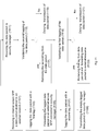
- Fig. 5 is a flowchart illustrating operations performed in accordance with the presently disclosed subject matter. The operations in Fig. 5 are described with reference to the network architecture presented in Fig. 4 .
- a secure SFP 210 say SFP 1
- router R3 to which the first computer is connected.
- a data packet is received in SFP 1 .
- each group is assigned with a different network-id that enables to differentiate between data packets transmitted by nodes of different groups.
- the uplinked data packed is tagged with the help of a network-id which is assigned to the respective network environment of the transmitting node (in this case the network-id which is assigned to group A) (block 503 ) .
- the network-id can be, stored for example, in SFP 1 (e.g. in data-repository 309 ) which connects the transmitting computer to router R3.
- the data packet comprises a payload and a header where the payload is the actual data and the header carries metadata which includes the destination and source of the data packet.
- the payload of the data packet can be tagged while the header remains unchanged.
- the tagging of an uplinked data packet can be performed by tagging module 301.
- Different types of network-ids and different methods can be used for tagging the data packet.
- a network-id can be a designated header (e.g. the VLAN standard header (802.1Q) can be used for tagging the data packet which is 4 bytes long), wherein the data packet can be tagged by adding the designated header to the payload.
- the data packet can be tagged with the help of a weak encryption (e.g. the network-id being a weak One-Time-Pad encryption with a fixed key) or a strong encryption (by using a strong encryption model with a matching key).
- the uplinked data packet is tagged by separation module 216 it is forwarded to switching fabric 202 in router R3 where it is routed to the secure SFP connecting the target computer terminal to router R3 (block 505 ). Routing can be accomplished based on the information in the data packet header which is left unmodified.
- Separation module 216 in the receiving secure SFP is configured to validate that the tag of the data packet is compatible with the network-id which is preprogrammed in the receiving secure SFP (block 507 ) and as mentioned above identifies the network environment of to the receiving secure SFP. Validation of the tagging of the data packet can be performed by validation module 303 in separation module 216.
- a single network environment can be allowed to communicate with several different other network environments (referred herein as "affiliated network environments").
- a single separation module 216 can be configured to allow the transmission of data arriving from a plurality of different network environments.
- data repository 309 can store a list of network-ids assigned to the affiliated network environments.
- Validation module 303 can be configured, during the validation stage (block 507 ) , to determine whether tagging of the data packet is compatible with any one of the network-ids of the affiliated network environments, which are stored in data-repository 309. In cases where the tag of an incoming data packet is compatible with one of the network-ids stored in data repository 309, the communication of the data packet is allowed.
- validation module 303 can simply compare between the designated header attached to the packet and the header which is expected by the receiving secure SFP.
- validation module 303 can be configured to check for example, whether the encryption key which is used, is the same encryption key that was assigned to the receiving secure SFP. For example, validation of the data can be performed by attempting to decrypt the encrypted payload. In such cases, separation module 216 can be configured to attempt to decrypt the encrypted payload. In cases where the decryption is successful, the transmission is allowed, and in cases where the decryption fails, transmission of data is denied.
- the tagging is removed and the stripped data packet is transmitted to the target node e.g. the destination computer terminal (block 509 ) . Removal of the tag can be accomplished, for example, with the help of stripping module 305 in separation module 216 of the receiving secure SFP. Otherwise, if the validation shows that the tagging of down-linked data packet is not compatible with the network-id assigned to the receiving SFP, the data packet data transmission to the target node is denied (block 511 ) .
- the mechanism described above with reference to Fig. 5 enables to enforce network environment separation. For example, since network environment separation is maintained by tagging data packets based on a network-id which is embedded within the SFP port and is not based on an identity of a node enclosed in the data packet's header, a deliberate attempt to send data from one node to another node in another network environment by altering the sender's address (i.e., a spoofing attack) would fail.
- any reference made in the description to a secure SFP is merely by way of a non-limiting example and the presently disclosed subject matter contemplates other implementations of a separation module, for example, in a printed circuit board which can be integrated as part of the network device's motherboard.
- Fig. 6 is a functional block diagram schematically illustrating another network-architecture, in accordance with the presently disclosed subject matter.
- Fig. 6 shows a similar architecture to one presented earlier in Fig. 1 .
- Fig. 6 shows an example of two Local Area Networks LAN11 and LAN21 which are connected over an encrypted VPN tunnel, established by two access routers ( R11 and R21 ) .
- LAN11 and LAN21 can represent for example local area networks of the same organization which are located at different locations on the globe, connected by a wide-area network (WAN).
- WAN wide-area network
- routers R11 and R21 on either sides of the network are connected each to a number of nodes.
- the nodes in LAN11 and LAN21 are divided into two departments, department A (e.g. engineering) and department B (e.g. accounting).
- the nodes in each group can be connected to an intermediate router (not shown) which facilitates the connection to routers R11 and R21.
- SFPs in routers R11 and R21 are secure SFPs configured in accordance with the teachings disclosed herein.
- Fig. 7 is a flowchart illustrating operations performed in accordance with the presently disclosed subject matter. The operations in Fig. 7 are described with reference to the network architecture presented in Fig. 6 .
- an uplinked data packet is transmitted from the transmitting computer terminal and received by a respective secure SFP 210 in router R11 .
- the uplinked data packet is processed by separation module 216 in secure SFP 210 and the uplinked data packed is tagged with the network-id assigned to that secure SFP 210 (block 703 ) .
- the data packet is transmitted from the internal secure SFP to an external secure SFP (block 705 ) .
- internal secure SFP refers to a secure SFP which connects between nodes in the same LAN. Internal secure SFP are described above with reference to Figs. 4 and 5 .
- external secure SFP refers to a secure SFP which connects between a LAN to an external domain such as another LAN, a public network (e.g. Internet), or any kind of shared resources.
- a first external secure SFP connects router R11 in LAN11 to a WAN (wide area network) connection ( ESFP 1 ) and a second external secure SFP connects router R21 in LAN21 to the WAN on the other side ( ESFP 2 ).
- Data packets are forwarded from an internal secure SFP in LAN11 to an external secure SFP connecting router R11 to the external network. Note that data packets which are transmitted to an external secure SFP from an internal secure SFP (down-linked data packets) are already tagged the first time by the internal secure SFP.
- a down-linked data packed which is received by an external secure SFP ( ESFP 1 ) is tagged a second time with a second tagging by the external secure SFP.
- the second tagging is based on a network-id assigned to the external SFP, and identifies the data packet as a data packet which was sent by an external SFP to an external network. Since the second tagging is assigned only by external secure SFP the data cannot be accessed by other internal SFP unless the second tagging is stripped first. This helps for example to protect against accidental or deliberate transmission of data to the wrong target.
- the second tagging can be accomplished for example with the help of an external network-id stored in data-repository 309 accessible to the external secured SFP.
- an external secure SFP (ESFP 2 ) in router R21 (block 709 ) .
- the transmitted data packet is received at an external secured SFP ( ESFP 2 ) in router R21 within LAN21 (block 711 ) where the receiving SFP is configured to validate the second tag (block 713 ) .
- the tag of the uplinked data packet is not compatible with the network-id assigned to the external secure SFP ( ESFP 2 ) in LAN21, transmission of the data packet is denied (block 715 ) .
- separation module 216 is configured to strip the second tag from the data packet and forward the data packet to its target internal secure SFP, based on the information in the header of the data packet (block 717 ).
- external secure SFPs and internal secure SFPs are configured differently. Although both types of SFPs perform similar operations, the directionality of the operations is inverted.
- separation module 216 can optionally comprise a direction determination module 307.
- Direction determination module 307 can be configured in accordance with the required functionality of separation module 216 and adapt the directionality of separation module 216.
- an internal separation module is configured to tag uplinked data packets and strip down-linked data packets
- an external separation module is configured to strip uplinked data packets and tag down-linked data packets.
- An external secure SFP can comprise an external separation module
- an internal secure SFP can comprise an internal separation module.
- the tagging is removed and the stripped data packet is transmitted to the target node (block 723 ) . This can be accomplished with the help of stripping module 305 in the receiving internal secure SFP. Otherwise, if the validation shows that the tagging of the incoming data packet is not compatible with the network-id assigned to the receiving internal SFP, transmission of data packet to target node is denied (block 721 ) .
- validation module 303 can be configured, during the validation stage (block 713 and block 719 ) , to determine whether tagging of the data packet is compatible with any one of the network-ids of the affiliated network environments, which are stored in data-repository 309. In cases where the tag of an incoming data packet is compatible with one of the network-ids stored in data repository 309 the communication of the data packet is allowed.
- Fig. 8 is a block diagram schematically illustrating another type of network architecture, in accordance with the presently disclosed subject matter.
- Fig. 8 shows LAN (LAN23 ) divided into two groups, group A and group B which are both connected to router R23.
- Router R23 is connected to a de-militarized zone (DMZ ) via a firewall FW.
- FW is also connected to security manager SM located within the DMZ and to some type of an external shared resource such as a public network (e.g. the Internet), or a shared printer or fax machine.
- a public network e.g. the Internet
- a shared printer or fax machine e.g. the Internet
- Firewall FW is configured for adding an additional layer of security between the local area network of the organization and an unreliable external resource. Firewall FW is configured to enforce a security policy in order to provide better security to the LAN, limiting leakage of information from the LANs to the external resource and the ability to attack the LANs from an external resource (e.g. external networks). To this end, FW can operate one or more firewall applications and possibly other security measures, such as intrusion detection and prevention devices, anti-virus and spam filters.
- Security manager SM is configured to provide additional security in accordance with the presently disclosed subject matter. As illustrated in Fig. 8 security manager SM can be implemented as an independent processing unit, which resides in the DMZ. In other cases security manger SM can be incorporated as an integral part of FW.
- Firewall FW and security manager SM may be, but are not limited to, personal or portable computers, a server computer or any other apparatus having the appropriate processing power for running the required operations and equipped with proper communication facilities and computer memory (including non-transitory computer memory).
- servers are often implemented as dedicated server-computers which are characterized by faster CPU, high performance RAM and possibly multiple hard drives and large storage space.
- Firewall FW and security manager SM are associated with at least one processor which is configured to manage and control relevant components and operations, and to perform tasks in response to instructions.
- Fig. 10 is a functional block diagram schematically illustrating a security manager SM, in accordance with the presently disclosed subject matter.
- SM can comprise separation module 216 or similar components including, tagging module 301, validation module 303 and stripping module 305.
- Security manager SM also comprises a network-id determination module 1010 and a data repository 1012 for storing addresses of different devices (e.g. nodes and network devices) in the network and their corresponding network-id.
- Security manager can also comprise a processing unit 1014.
- a more detailed description of the operations of the different modules in security manager is provided below with reference to Fig. 9 .
- Fig. 9 is a flowchart illustrating operations performed, in accordance with the presently disclosed subject matter. The operations in Fig. 9 are described with reference to the network architecture presented in Fig. 8 .
- a data packet transmitted from a source external to LAN23 is received in security manager SM.
- the data packet is destined to a node in LAN23.
- Security manager SM utilizes the destination address of the target node, which is specified in the header of the data packet, to search in data-repository 1012 and locate the respective network-id assigned to the internal secure SFP which is connected to the requested target node.
- security manager SM identifies the network-id which was assigned to an external secure SFP ( ESFP ) which connects security manger SM to router R23 (block 903 ) . This can be accomplished with the help of network-id determination module 1010.
- security manager SM tags the incoming data packet with a first tag (corresponding to target internal-secure-SFP) and a second tagging (corresponding to target external- secure-SFP) (block 905 ) .
- SM can determine whether an incoming data packet destined to a certain target device is authorized to be sent to the requested target. This can be accomplished for example by FW. In case it is determine that the data packet can be forwarded to the requested target (e.g. it does not include malicious content), it can tag the data packet as explained above. Otherwise the transmission of the data can be denied.
- the doubly tagged data packet is then transmitted by security manager SM to an external secure SFP connected to the target LAN, which is in the current example router R1 in LAN23 (block 907 ) .
- the data packet is received in the external secure SFP (block 909 ) where the SFP determines whether the second tagging of the data packet is in agreement with the network-id which was assigned to the external secure SFP e.g. with the help of validation module 303 (block 911 ) .
- the second tagging is removed from the data packet and the data packet is transmitted to the target internal-secure-SFP which is the SFP connected to the target node (block 913 ) . Removal of the tag can be accomplished with the help of stripping module 305 in the external SFP ( ESFP ) . Otherwise, if the validation shows that the tagging of the incoming data packet is not compatible with the network-id assigned to the external secured SFP ( ESFP ) further transmission of the data packet is denied (block 915 ) .
- the data packet, now tagged only with the first tag is received by the internal secure SFP ( ISFP in Fig. 8 ) connected to the target node, where the first tag of the payload is validated e.g. with the help of validating module 303.
- the validation shows that tagging of the incoming data packet is compatible with the network-id assigned to the internal secure SFP ( ISFP )
- the first tagging is removed from the data packet and the stripped data packet is transmitted to the target node (block 921 ) .
- the validation shows that the tagging of the incoming data packet is not compatible with the network-id assigned to the internal secure SFP, further transmission of the data packet is denied and the data packet is discarded (block 923 ) .
- This configuration of a DMZ can help to ensure that only data packets that passed through the DMZ (and FW in the DMZ ) are allowed to be transmitted to the requested destination (in this case LAN23 ) .
- Fig. 11 is a flowchart illustrating operations performed in accordance with the presently disclosed subject matter. The operations in Fig. 11 are described with reference to the network architecture presented in Fig. 8 and refer to transmission of data from LAN23 towards the external resource via security manager SM.
- a data packet is transmitted from a node and received by the respective internal secure SFP in router R23.
- the uplinked data packet is processed by separation module 216 located in the internal secure SFP (e.g. ISFP ) and the payload of the outgoing data packed is tagged based on the network-id assigned to the internal secure SFP 210 (block 1103 ) .
- separation module 216 located in the internal secure SFP (e.g. ISFP ) and the payload of the outgoing data packed is tagged based on the network-id assigned to the internal secure SFP 210 (block 1103 ) .
- the data packet is transmitted from the internal secure SFP to an external secure SFP (ESFP in Fig. 8 ) which is connected to security manager SM in DMZ (block 1105 ) .
- ESFP secure SFP
- DMZ security manager SM in DMZ
- a tagged data packed which is received by an external secure SFP is tagged a second time with a second tagging by the external secure SFP (block 1107 ) .
- the second tagging identifies the data packet as a data packet which was sent by an external SFP to an external resource. After the data is tagged for the second time, it is transmitted to security manager SM (block 1109 ) .
- the transmitted data block is received at security manager (block 1111 ) where the security manager is configured to validate the second tagging of the data packet e.g. with the help of validation module 303 (block 1113 ) .
- network-id determination module 1010 is used to locate in data repository 1012 , the network-id of the source external secure SFP ( ESFP ) .
- the network-id is used by security manager SM to validate the second tagging of the payload.
- stripping module in security manager is configured to remove the second tagging from the data packet (block 1117 ) .
- security manager validates the first tagging of the data packet e.g. with the help of validation module 303.
- network-id determination module 1010 is used to locate in data repository 1012, the network-id of the source internal secure SFP.
- the network-id is used by security manager SM to validate the second tagging of the payload.
- the stripping module in the security manager is configured to remove the first tagging from the payload and forward the data packet to the external resource (block 1123 ) .
- data repository 1012 can comprise data indicating whether data transmitted from a device (e.g. node or network device) associated with a certain network environment is allowed be transmitted to the external network connected to SM.
- validation performed by validation module 303 includes determining whether the first and second tag identify a devices in a network environment which are allowed to transmit data to the external network.
- validation module 303 can be configured, during the validation stage (block 911 and block 917 in Fig. 9 and 1113 and 1119 in Fig. 11 ) , to determine whether tagging of the data packet is compatible with any one of the network-ids of the affiliated network environments, which are stored in data-repository 309. In cases where the tag of an incoming data packet is compatible with one of the network-ids stored in data repository 309 the communication of the data packet is allowed.
- the mechanism described above with reference to Figs. 8 and Fig. 11 enables to enforce restrictions on data communication. For example, since network environment separation is maintained by tagging data packets based on a network-id which is embedded within the SFP port and is not based on an identity of a node enclosed in the data packet's header, a deliberate attempt to send data from an unauthorized node inside LAN23 to another node located outside LAN23 by altering the sender's address (i.e., a spoofing attack) would be intercepted by security monitor SM.
- the presently disclosed subject matter may be implemented in a suitably programmed computer.
- the presently disclosed subject matter includes a computer program being readable by a computer for executing the method of the presently disclosed subject matter.
- the presently disclosed subject matter further contemplates a machine-readable memory tangibly embodying a program of instructions executable by the machine for executing the method of the presently disclosed subject matter.
- the machine-readable memory includes non-transitory machine-readable computer memory such as for example, CD-ROM, memory device, hard drive, etc.
Claims (18)
- Module de séparation (216), configuré de manière à commander une transmission de données entre différents noeuds dans un réseau :le module de séparation pouvant être fonctionnellement connecté entre une couche physique, « phy », (214), et une matrice de commutation respective (204) dans un dispositif de réseau (202) exploitable de manière à communiquer des données dans un réseau de communication ; le module de séparation (216) étant configuré de manière à commander une communication de données dans le réseau de communication, le module de séparation (216) comportant un identifiant de réseau affecté associant le module de séparation à un environnement de réseau donné ; dans lequel l'environnement de réseau comporte un groupe (A, B, C) d'un ou plusieurs noeuds au sein du réseau ; le module de séparation étant en outre configuré de manière à :étiqueter, sur la base de l'identifiant de réseau, une charge utile d'un paquet de données reçu par le dispositif de réseau (202), à acheminer dans une première direction, afin d'associer le paquet de données à l'environnement de réseau donné ; etdéterminer si une étiquette, associée à une charge utile d'un paquet de données reçu par le dispositif de réseau (202), à acheminer dans une seconde direction, est compatible avec l'identifiant de réseau affecté, et, le cas échéant, supprimer l'étiquette de la charge utile du paquet de données et permettre la transmission du paquet de données entre des noeuds qui font partie du même environnement de réseau.
- Module de séparation selon la revendication 1, dans lequel la première direction est une direction en liaison montante vers la matrice de commutation (204) du dispositif de réseau (202), et la seconde direction est une direction en liaison descendante qui s'écarte de la matrice de commutation du dispositif de réseau.
- Module de séparation selon la revendication 1, lequel est un module de séparation dans lequel la première direction est une direction en liaison descendante qui s'écarte de la matrice de commutation (204) du dispositif de réseau (202) et la seconde direction est une direction en liaison montante vers la matrice de commutation du dispositif de réseau.
- Module de séparation selon la revendication 1, comportant un module de détermination de direction configuré de manière à amener le module de séparation à fonctionner selon l'un parmi un premier mode de fonctionnement ou un second mode de fonctionnement, dans lequel, dans le premier mode de fonctionnement, la première direction est une direction en liaison montante vers la matrice de commutation du dispositif de réseau et la seconde direction est une direction en liaison descendante qui s'écarte d'une matrice de commutation (204) du dispositif de réseau (202), et, dans le second mode de fonctionnement, la première direction est une direction en liaison descendante qui s'écarte de la matrice de commutation du dispositif de réseau et la seconde direction est une direction en liaison montante vers la matrice de commutation (204) du dispositif de réseau.
- Module de séparation selon la revendication 1, lequel est configuré en tant qu'un dispositif de mémoire protégé en écriture.
- Module de séparation selon la revendication 1, comportant une pluralité d'identifiants de réseaux affectés, chaque identifiant de réseau étant affecté à un environnement de réseau respectif ; dans lequel chaque environnement de réseau comporte un groupe prédéfini d'un ou plusieurs noeuds au sein du réseau ; le module de séparation (216) étant en outre configuré de manière à déterminer si une étiquette, associée à une charge utile d'un paquet de données reçu par le dispositif de réseau à partir de la seconde direction, est compatible avec l'un quelconque de la pluralité d'identifiants de réseaux, et le cas échéant, à supprimer l'étiquette de la charge utile du paquet de données et à permettre la transmission du paquet de données.
- Module de séparation (216) selon la revendication 6, comportant un référentiel de données destiné à stocker la pluralité d'identifiants de réseaux.
- Module de séparation selon la revendication 1, comportant en outre :un référentiel de données destiné à stocker l'identifiant de réseau, et un processeur associé à un module d'étiquetage configuré de manière à mettre en oeuvre l'étiquetage ; et un module de validation configuré de manière à déterminer si l'étiquette est compatible avec le module de séparation.
- Gestionnaire de sécurité des informations, comportant le module de séparation selon la revendication 1 ;
dans lequel le gestionnaire de sécurité est connecté de manière fonctionnelle à un dispositif de réseau et à un réseau externe, et est exploitable de manière à commander une transmission de données entre le dispositif de réseau et le réseau externe ; et le gestionnaire de sécurité est connecté de manière fonctionnelle à un référentiel de données configuré de manière à stocker des identifiants de réseaux ;
le module de séparation est configuré de manière à :recevoir un paquet de données, envoyé par le biais d'un module de séparation externe dans le dispositif de réseau ; le paquet de données comportant une première étiquette et une seconde étiquette ;déterminer si la seconde étiquette, associée au paquet de données, est compatible avec l'un quelconque parmi des identifiants de réseaux stockés dans le référentiel de données ;le cas échéant, supprimer l'étiquette du paquet de données ; etdéterminer si la première étiquette, associée au paquet de données, est compatible avec l'un quelconque parmi des identifiants de réseaux stockés dans le référentiel de données ;le cas échéant, supprimer l'étiquette du paquet de données ; etpermettre la transmission du paquet de données au réseau externe. - Dispositif de réseau configuré de manière à commander une communication de données entre des noeuds associés à un ou plusieurs environnements de réseau ; dans lequel l'environnement de réseau comporte un groupe (A, B, C) d'un ou plusieurs noeuds au sein du réseau ; le dispositif de réseau comportant :au moins un premier module de séparation et un second module de séparation, dans lequel un module de séparation (216) est configuré de manière à commander une transmission de données entre différents noeuds dans un réseau ;le premier module de séparation étant connecté de manière fonctionnelle à un premier noeud connecté au dispositif de réseau ;le premier module de séparation et le second module de séparation étant chacun connectés de manière fonctionnelle entre une couche physique respective (phy) du dispositif de réseau et une matrice de commutation respective ;dans lequel le premier module de séparation est configuré de manière à étiqueter une charge utile d'un paquet de données reçu en provenance du premier noeud, sur la base d'un identifiant de réseau affecté au premier module de séparation, l'étiquette étant indicative d'un environnement de réseau respectif du premier noeud ; et à transmettre le paquet de données vers le second module de séparation.
- Dispositif de réseau selon la revendication 10, dans lequel le second module de séparation est connecté de manière fonctionnelle à un second noeud connecté au dispositif de réseau ;
le second module de séparation est configuré de manière à :recevoir le paquet de données ;déterminer si l'étiquette associée au paquet de données est compatible avec le second module de séparation ; et le cas échéant,supprimer l'étiquette de la charge utile du paquet de données et permettre la transmission du paquet de données au second noeud. - Dispositif de réseau selon la revendication 10, dans lequel le second module de séparation est un module de séparation externe connectant le dispositif de réseau à un second dispositif de réseau ;
le module de séparation externe est configuré de manière à :étiqueter la charge utile du paquet de données reçu en provenance du premier module de séparation, avec une seconde étiquette, la seconde étiquette étant indicative d'un environnement de réseau respectif du dispositif de réseau ; et transmettre le paquet de données vers le second dispositif de réseau. - Dispositif de réseau selon la revendication 12, dans lequel le module de séparation externe est configuré de manière à :recevoir un paquet de données envoyé à partir d'un second noeud connecté au second dispositif de réseau ; le paquet de données comportant une première étiquette et une seconde étiquette ;déterminer si la seconde étiquette, associée au paquet de données, est compatible avec le module de séparation externe ;le cas échéant, supprimer l'étiquette de la charge utile du paquet de données ;transmettre le paquet de données au module de séparation ; le module de séparation étant configuré de manière à :déterminer si la première étiquette, associée au paquet de données, est compatible avec le module de séparation ;le cas échéant, supprimer l'étiquette du paquet de données ; ettransmettre le paquet de données à un noeud connecté au dispositif de réseau.
- Émetteur-récepteur sécurisé enfichable de faible encombrement, SFP, comportant le module de séparation selon la revendication 1, l'émetteur-récepteur SFP pouvant être connecté de manière fonctionnelle à un dispositif de réseau en vue de commander une communication de données avec le dispositif de réseau dans un réseau de communication.
- Procédé de commande de transmission de données dans un réseau de communication, le procédé comportant la mise en oeuvre, dans un dispositif de réseau (202), des étapes ci-dessous consistant à :étiqueter une charge utile d'un paquet de données reçu par un dispositif de réseau (202), à acheminer dans une première direction dans le réseau de communication ; l'étiquetage étant mis en oeuvre par un module de séparation (216) qui est connecté entre une couche physique, phy, et une matrice de commutation du dispositif de réseau, et étant affecté sur la base d'un identifiant de réseau au dispositif de réseau ; l'identifiant de réseau indiquant que le paquet de données est associé à un environnement de réseau donné ; dans lequel l'environnement de réseau comporte un groupe (A, B, C) d'un ou plusieurs noeuds au sein du réseau ; etdéterminer si une étiquette associée à une charge utile d'un paquet de données, reçu par le dispositif de réseau (202), à acheminer dans une seconde direction, est compatible avec un identifiant de réseau affecté à un dispositif cible, et le cas échéant, supprimer l'étiquette de la charge utile du paquet de données et permettre la transmission du paquet de données au dispositif cible.
- Procédé selon la revendication 15, dans lequel la première direction est une direction en liaison montante vers la matrice de commutation du dispositif de réseau (202) et la seconde direction est une direction en liaison descendante qui s'écarte de la matrice de commutation du dispositif de réseau.
- Procédé selon la revendication 15, dans lequel la première direction est une direction en liaison descendante qui s'écarte de la matrice de commutation du dispositif de réseau (202) et la seconde direction est une direction en liaison montante vers la matrice de commutation du dispositif de réseau.
- Procédé selon la revendication 15, dans lequel le dispositif de réseau (202) est connecté à un premier noeud et à un second noeud, le procédé comportant les étapes ci-dessous consistant à :mettre en oeuvre, en utilisant un premier module de séparation connectant le premier noeud au dispositif, l'étiquetage sur une charge utile d'un paquet de données reçu en provenance d'un premier noeud connecté au dispositif de réseau ; etmettre en oeuvre, en utilisant un second module de séparation connectant le second noeud au dispositif, la détermination sur le paquet de données transmis à un second noeud connecté au dispositif de réseau (202) ; ce qui permet par conséquent de commander la transmission de données entre le premier noeud et le second noeud.
Applications Claiming Priority (2)
| Application Number | Priority Date | Filing Date | Title |
|---|---|---|---|
| IL214830A IL214830A0 (en) | 2011-08-25 | 2011-08-25 | Network environment separation |
| PCT/IL2012/050321 WO2013027218A2 (fr) | 2011-08-25 | 2012-08-22 | Séparation d'environnement de réseau |
Publications (2)
| Publication Number | Publication Date |
|---|---|
| EP2748981A2 EP2748981A2 (fr) | 2014-07-02 |
| EP2748981B1 true EP2748981B1 (fr) | 2017-11-22 |
Family
ID=45855129
Family Applications (1)
| Application Number | Title | Priority Date | Filing Date |
|---|---|---|---|
| EP12768907.3A Not-in-force EP2748981B1 (fr) | 2011-08-25 | 2012-08-22 | Séparation d'environnement de réseau |
Country Status (7)
| Country | Link |
|---|---|
| US (1) | US9515992B2 (fr) |
| EP (1) | EP2748981B1 (fr) |
| KR (1) | KR20140059818A (fr) |
| CN (1) | CN103828307A (fr) |
| IL (2) | IL214830A0 (fr) |
| SG (2) | SG11201400190VA (fr) |
| WO (1) | WO2013027218A2 (fr) |
Families Citing this family (14)
| Publication number | Priority date | Publication date | Assignee | Title |
|---|---|---|---|---|
| IL214867A0 (en) | 2011-08-29 | 2012-01-31 | Elta Systems Ltd | Moving cellular communicatio system |
| US9813384B2 (en) * | 2012-10-31 | 2017-11-07 | The Boeing Company | Time-locked network and nodes for exchanging secure data packets |
| US9549234B1 (en) * | 2012-12-28 | 2017-01-17 | Enginuity Communications Corporation | Methods and apparatuses for implementing a layer 3 internet protocol (IP) echo response function on a small form-factor pluggable (SFP) transceiver and providing a universal interface between an SFP transceiver and network equipment |
| US9424937B2 (en) * | 2013-02-25 | 2016-08-23 | U.S. Department Of Energy | Method for programming a flash memory |
| US10110710B2 (en) | 2014-04-03 | 2018-10-23 | Centurylink Intellectual Property Llc | System and method for implementing extension of customer LAN at provider network service point |
| US10698569B2 (en) | 2014-04-03 | 2020-06-30 | Centurylink Intellectual Property Llc | System and method for implementing customer control point or customer portal |
| US10673978B2 (en) | 2015-05-06 | 2020-06-02 | Centurylink Intellectual Property Llc | Method and system for implementing network experience shifting using shared objects |
| US10481938B2 (en) | 2015-05-06 | 2019-11-19 | Centurylink Intellectual Property Llc | System and method for implementing network experience shifting |
| CN106302157B (zh) * | 2015-05-11 | 2020-09-29 | 中兴通讯股份有限公司 | 报文发送方法及装置 |
| US10673893B2 (en) * | 2016-08-31 | 2020-06-02 | International Business Machines Corporation | Isolating a source of an attack that originates from a shared computing environment |
| US10374835B2 (en) * | 2017-06-12 | 2019-08-06 | Centurylink Intellectual Property Llc | Universal broadband network gateway |
| US10667118B2 (en) * | 2018-04-10 | 2020-05-26 | C LAN Wireless, Inc. | Synchronous communications in a multiple-input synchronous transfer network |
| US11218494B2 (en) * | 2019-07-26 | 2022-01-04 | Raise Marketplace, Llc | Predictive fraud analysis system for data transactions |
| KR102422152B1 (ko) * | 2022-04-20 | 2022-07-18 | 아토리서치(주) | SDN 기반 ITS 네트워크에서 현장 인프라 관리자에 따라 가상 네트워크를 분리하는 vCPE 디바이스와 그 동작 방법 |
Family Cites Families (9)
| Publication number | Priority date | Publication date | Assignee | Title |
|---|---|---|---|---|
| US6912592B2 (en) | 2001-01-05 | 2005-06-28 | Extreme Networks, Inc. | Method and system of aggregate multiple VLANs in a metropolitan area network |
| US7093280B2 (en) * | 2001-03-30 | 2006-08-15 | Juniper Networks, Inc. | Internet security system |
| US7188364B2 (en) * | 2001-12-20 | 2007-03-06 | Cranite Systems, Inc. | Personal virtual bridged local area networks |
| US7782784B2 (en) * | 2003-01-10 | 2010-08-24 | Cisco Technology, Inc. | Port analyzer adapter |
| FI116382B (fi) | 2003-04-22 | 2005-11-15 | Liekki Oy | Menetelmä hiukkasten varaamiseksi materiaalin valmistusprosessissa sekä hiukkasten varauslaite |
| US7869450B2 (en) | 2004-04-05 | 2011-01-11 | Verizon Business Global Llc | Method and apparatus for processing labeled flows in a communication access network |
| US7389377B2 (en) * | 2005-06-22 | 2008-06-17 | Netlogic Microsystems, Inc. | Access control list processor |
| US20090080421A1 (en) | 2007-09-21 | 2009-03-26 | Ou Frank Y | Data flow mirroring |
| US9497039B2 (en) | 2009-05-28 | 2016-11-15 | Microsoft Technology Licensing, Llc | Agile data center network architecture |
-
2011
- 2011-08-25 IL IL214830A patent/IL214830A0/en unknown
-
2012
- 2012-08-22 SG SG11201400190VA patent/SG11201400190VA/en unknown
- 2012-08-22 EP EP12768907.3A patent/EP2748981B1/fr not_active Not-in-force
- 2012-08-22 WO PCT/IL2012/050321 patent/WO2013027218A2/fr active Application Filing
- 2012-08-22 KR KR1020147007583A patent/KR20140059818A/ko not_active Application Discontinuation
- 2012-08-22 CN CN201280046710.7A patent/CN103828307A/zh active Pending
- 2012-08-22 SG SG10201604184RA patent/SG10201604184RA/en unknown
- 2012-08-22 US US14/240,863 patent/US9515992B2/en active Active
-
2014
- 2014-02-24 IL IL231099A patent/IL231099A/en active IP Right Grant
Also Published As
| Publication number | Publication date |
|---|---|
| SG11201400190VA (en) | 2014-05-29 |
| US20150052600A1 (en) | 2015-02-19 |
| SG10201604184RA (en) | 2016-07-28 |
| US9515992B2 (en) | 2016-12-06 |
| CN103828307A (zh) | 2014-05-28 |
| EP2748981A2 (fr) | 2014-07-02 |
| IL214830A0 (en) | 2012-02-29 |
| IL231099A0 (en) | 2014-04-30 |
| KR20140059818A (ko) | 2014-05-16 |
| IL231099A (en) | 2017-08-31 |
| WO2013027218A3 (fr) | 2013-07-04 |
| WO2013027218A2 (fr) | 2013-02-28 |
Similar Documents
| Publication | Publication Date | Title |
|---|---|---|
| EP2748981B1 (fr) | Séparation d'environnement de réseau | |
| US10491569B1 (en) | Secure transfer of independent security domains across shared media | |
| US10484278B2 (en) | Application-based network packet forwarding | |
| EP3210345B1 (fr) | Serveurs mandataires de trajet d'en-tête de service de réseau transparent | |
| JP6236528B2 (ja) | ネットワークルーティングのためのパケット分類 | |
| CN106487719B (zh) | 经由分组中继使网络功能外部化的系统和方法 | |
| US7886145B2 (en) | Method and system for including security information with a packet | |
| EP3254418B1 (fr) | Brouillage de paquet et transfert de paquet | |
| US7873038B2 (en) | Packet processing | |
| EP2213045B1 (fr) | Pare-feu au courant de l'état de sécurité | |
| US7738457B2 (en) | Method and system for virtual routing using containers | |
| US7792990B2 (en) | Remote client remediation | |
| EP1712056B1 (fr) | Groupes de securite tunnelise | |
| US20160043996A1 (en) | Secure path determination between devices | |
| MXPA06013129A (es) | Contencion automatizada de un invasor en redes. | |
| CN106341423B (zh) | 一种报文处理方法和装置 | |
| US11330017B2 (en) | Method and device for providing a security service | |
| Yoon et al. | Poster: Address shuffling based moving target defense for in-vehicle software-defined networks | |
| EP1987440B1 (fr) | Procédé et système pour éliminer des actions redondantes dans un réseau | |
| Leischner et al. | Security through VLAN segmentation: Isolating and securing critical assets without loss of usability | |
| US20230388270A1 (en) | Method and device for prioritising packet flows | |
| Gross et al. | RFC 8926: Geneve: Generic Network Virtualization Encapsulation | |
| EP2940944B1 (fr) | Procédé et dispositif de traitement de paquet dans un réseau trill | |
| Huang et al. | On the design of a cost effective network security switch architecture |
Legal Events
| Date | Code | Title | Description |
|---|---|---|---|
| PUAI | Public reference made under article 153(3) epc to a published international application that has entered the european phase |
Free format text: ORIGINAL CODE: 0009012 |
|
| 17P | Request for examination filed |
Effective date: 20140306 |
|
| AK | Designated contracting states |
Kind code of ref document: A2 Designated state(s): AL AT BE BG CH CY CZ DE DK EE ES FI FR GB GR HR HU IE IS IT LI LT LU LV MC MK MT NL NO PL PT RO RS SE SI SK SM TR |
|
| DAX | Request for extension of the european patent (deleted) | ||
| 17Q | First examination report despatched |
Effective date: 20150331 |
|
| REG | Reference to a national code |
Ref country code: DE Ref legal event code: R079 Ref document number: 602012040113 Country of ref document: DE Free format text: PREVIOUS MAIN CLASS: H04L0012460000 Ipc: H04L0029060000 |
|
| RIC1 | Information provided on ipc code assigned before grant |
Ipc: H04L 12/46 20060101ALI20170428BHEP Ipc: H04L 29/06 20060101AFI20170428BHEP |
|
| GRAP | Despatch of communication of intention to grant a patent |
Free format text: ORIGINAL CODE: EPIDOSNIGR1 |
|
| STAA | Information on the status of an ep patent application or granted ep patent |
Free format text: STATUS: GRANT OF PATENT IS INTENDED |
|
| INTG | Intention to grant announced |
Effective date: 20170620 |
|
| GRAS | Grant fee paid |
Free format text: ORIGINAL CODE: EPIDOSNIGR3 |
|
| GRAA | (expected) grant |
Free format text: ORIGINAL CODE: 0009210 |
|
| STAA | Information on the status of an ep patent application or granted ep patent |
Free format text: STATUS: THE PATENT HAS BEEN GRANTED |
|
| AK | Designated contracting states |
Kind code of ref document: B1 Designated state(s): AL AT BE BG CH CY CZ DE DK EE ES FI FR GB GR HR HU IE IS IT LI LT LU LV MC MK MT NL NO PL PT RO RS SE SI SK SM TR |
|
| REG | Reference to a national code |
Ref country code: GB Ref legal event code: FG4D |
|
| REG | Reference to a national code |
Ref country code: CH Ref legal event code: EP |
|
| REG | Reference to a national code |
Ref country code: IE Ref legal event code: FG4D |
|
| REG | Reference to a national code |
Ref country code: AT Ref legal event code: REF Ref document number: 949371 Country of ref document: AT Kind code of ref document: T Effective date: 20171215 |
|
| REG | Reference to a national code |
Ref country code: DE Ref legal event code: R096 Ref document number: 602012040113 Country of ref document: DE |
|
| REG | Reference to a national code |
Ref country code: CH Ref legal event code: NV Representative=s name: SERVOPATENT GMBH, CH |
|
| REG | Reference to a national code |
Ref country code: NL Ref legal event code: FP |
|
| REG | Reference to a national code |
Ref country code: LT Ref legal event code: MG4D |
|
| REG | Reference to a national code |
Ref country code: AT Ref legal event code: MK05 Ref document number: 949371 Country of ref document: AT Kind code of ref document: T Effective date: 20171122 |
|
| PG25 | Lapsed in a contracting state [announced via postgrant information from national office to epo] |
Ref country code: FI Free format text: LAPSE BECAUSE OF FAILURE TO SUBMIT A TRANSLATION OF THE DESCRIPTION OR TO PAY THE FEE WITHIN THE PRESCRIBED TIME-LIMIT Effective date: 20171122 Ref country code: NO Free format text: LAPSE BECAUSE OF FAILURE TO SUBMIT A TRANSLATION OF THE DESCRIPTION OR TO PAY THE FEE WITHIN THE PRESCRIBED TIME-LIMIT Effective date: 20180222 Ref country code: LT Free format text: LAPSE BECAUSE OF FAILURE TO SUBMIT A TRANSLATION OF THE DESCRIPTION OR TO PAY THE FEE WITHIN THE PRESCRIBED TIME-LIMIT Effective date: 20171122 Ref country code: SE Free format text: LAPSE BECAUSE OF FAILURE TO SUBMIT A TRANSLATION OF THE DESCRIPTION OR TO PAY THE FEE WITHIN THE PRESCRIBED TIME-LIMIT Effective date: 20171122 Ref country code: ES Free format text: LAPSE BECAUSE OF FAILURE TO SUBMIT A TRANSLATION OF THE DESCRIPTION OR TO PAY THE FEE WITHIN THE PRESCRIBED TIME-LIMIT Effective date: 20171122 |
|
| PG25 | Lapsed in a contracting state [announced via postgrant information from national office to epo] |
Ref country code: GR Free format text: LAPSE BECAUSE OF FAILURE TO SUBMIT A TRANSLATION OF THE DESCRIPTION OR TO PAY THE FEE WITHIN THE PRESCRIBED TIME-LIMIT Effective date: 20180223 Ref country code: HR Free format text: LAPSE BECAUSE OF FAILURE TO SUBMIT A TRANSLATION OF THE DESCRIPTION OR TO PAY THE FEE WITHIN THE PRESCRIBED TIME-LIMIT Effective date: 20171122 Ref country code: RS Free format text: LAPSE BECAUSE OF FAILURE TO SUBMIT A TRANSLATION OF THE DESCRIPTION OR TO PAY THE FEE WITHIN THE PRESCRIBED TIME-LIMIT Effective date: 20171122 Ref country code: BG Free format text: LAPSE BECAUSE OF FAILURE TO SUBMIT A TRANSLATION OF THE DESCRIPTION OR TO PAY THE FEE WITHIN THE PRESCRIBED TIME-LIMIT Effective date: 20180222 Ref country code: LV Free format text: LAPSE BECAUSE OF FAILURE TO SUBMIT A TRANSLATION OF THE DESCRIPTION OR TO PAY THE FEE WITHIN THE PRESCRIBED TIME-LIMIT Effective date: 20171122 Ref country code: AT Free format text: LAPSE BECAUSE OF FAILURE TO SUBMIT A TRANSLATION OF THE DESCRIPTION OR TO PAY THE FEE WITHIN THE PRESCRIBED TIME-LIMIT Effective date: 20171122 |
|
| PG25 | Lapsed in a contracting state [announced via postgrant information from national office to epo] |
Ref country code: CZ Free format text: LAPSE BECAUSE OF FAILURE TO SUBMIT A TRANSLATION OF THE DESCRIPTION OR TO PAY THE FEE WITHIN THE PRESCRIBED TIME-LIMIT Effective date: 20171122 Ref country code: EE Free format text: LAPSE BECAUSE OF FAILURE TO SUBMIT A TRANSLATION OF THE DESCRIPTION OR TO PAY THE FEE WITHIN THE PRESCRIBED TIME-LIMIT Effective date: 20171122 Ref country code: DK Free format text: LAPSE BECAUSE OF FAILURE TO SUBMIT A TRANSLATION OF THE DESCRIPTION OR TO PAY THE FEE WITHIN THE PRESCRIBED TIME-LIMIT Effective date: 20171122 Ref country code: SK Free format text: LAPSE BECAUSE OF FAILURE TO SUBMIT A TRANSLATION OF THE DESCRIPTION OR TO PAY THE FEE WITHIN THE PRESCRIBED TIME-LIMIT Effective date: 20171122 Ref country code: CY Free format text: LAPSE BECAUSE OF FAILURE TO SUBMIT A TRANSLATION OF THE DESCRIPTION OR TO PAY THE FEE WITHIN THE PRESCRIBED TIME-LIMIT Effective date: 20171122 |
|
| REG | Reference to a national code |
Ref country code: DE Ref legal event code: R097 Ref document number: 602012040113 Country of ref document: DE |
|
| REG | Reference to a national code |
Ref country code: FR Ref legal event code: PLFP Year of fee payment: 7 |
|
| PG25 | Lapsed in a contracting state [announced via postgrant information from national office to epo] |
Ref country code: PL Free format text: LAPSE BECAUSE OF FAILURE TO SUBMIT A TRANSLATION OF THE DESCRIPTION OR TO PAY THE FEE WITHIN THE PRESCRIBED TIME-LIMIT Effective date: 20171122 Ref country code: RO Free format text: LAPSE BECAUSE OF FAILURE TO SUBMIT A TRANSLATION OF THE DESCRIPTION OR TO PAY THE FEE WITHIN THE PRESCRIBED TIME-LIMIT Effective date: 20171122 Ref country code: IT Free format text: LAPSE BECAUSE OF FAILURE TO SUBMIT A TRANSLATION OF THE DESCRIPTION OR TO PAY THE FEE WITHIN THE PRESCRIBED TIME-LIMIT Effective date: 20171122 Ref country code: SM Free format text: LAPSE BECAUSE OF FAILURE TO SUBMIT A TRANSLATION OF THE DESCRIPTION OR TO PAY THE FEE WITHIN THE PRESCRIBED TIME-LIMIT Effective date: 20171122 |
|
| PLBE | No opposition filed within time limit |
Free format text: ORIGINAL CODE: 0009261 |
|
| STAA | Information on the status of an ep patent application or granted ep patent |
Free format text: STATUS: NO OPPOSITION FILED WITHIN TIME LIMIT |
|
| 26N | No opposition filed |
Effective date: 20180823 |
|
| PG25 | Lapsed in a contracting state [announced via postgrant information from national office to epo] |
Ref country code: SI Free format text: LAPSE BECAUSE OF FAILURE TO SUBMIT A TRANSLATION OF THE DESCRIPTION OR TO PAY THE FEE WITHIN THE PRESCRIBED TIME-LIMIT Effective date: 20171122 |
|
| PG25 | Lapsed in a contracting state [announced via postgrant information from national office to epo] |
Ref country code: MC Free format text: LAPSE BECAUSE OF FAILURE TO SUBMIT A TRANSLATION OF THE DESCRIPTION OR TO PAY THE FEE WITHIN THE PRESCRIBED TIME-LIMIT Effective date: 20171122 |
|
| PG25 | Lapsed in a contracting state [announced via postgrant information from national office to epo] |
Ref country code: LU Free format text: LAPSE BECAUSE OF NON-PAYMENT OF DUE FEES Effective date: 20180822 |
|
| REG | Reference to a national code |
Ref country code: BE Ref legal event code: MM Effective date: 20180831 |
|
| PG25 | Lapsed in a contracting state [announced via postgrant information from national office to epo] |
Ref country code: BE Free format text: LAPSE BECAUSE OF NON-PAYMENT OF DUE FEES Effective date: 20180831 |
|
| PG25 | Lapsed in a contracting state [announced via postgrant information from national office to epo] |
Ref country code: MT Free format text: LAPSE BECAUSE OF NON-PAYMENT OF DUE FEES Effective date: 20180822 |
|
| PG25 | Lapsed in a contracting state [announced via postgrant information from national office to epo] |
Ref country code: TR Free format text: LAPSE BECAUSE OF FAILURE TO SUBMIT A TRANSLATION OF THE DESCRIPTION OR TO PAY THE FEE WITHIN THE PRESCRIBED TIME-LIMIT Effective date: 20171122 |
|
| PG25 | Lapsed in a contracting state [announced via postgrant information from national office to epo] |
Ref country code: HU Free format text: LAPSE BECAUSE OF FAILURE TO SUBMIT A TRANSLATION OF THE DESCRIPTION OR TO PAY THE FEE WITHIN THE PRESCRIBED TIME-LIMIT; INVALID AB INITIO Effective date: 20120822 Ref country code: PT Free format text: LAPSE BECAUSE OF FAILURE TO SUBMIT A TRANSLATION OF THE DESCRIPTION OR TO PAY THE FEE WITHIN THE PRESCRIBED TIME-LIMIT Effective date: 20171122 |
|
| REG | Reference to a national code |
Ref country code: CH Ref legal event code: PCAR Free format text: NEW ADDRESS: WANNERSTRASSE 9/1, 8045 ZUERICH (CH) |
|
| PG25 | Lapsed in a contracting state [announced via postgrant information from national office to epo] |
Ref country code: MK Free format text: LAPSE BECAUSE OF NON-PAYMENT OF DUE FEES Effective date: 20171122 Ref country code: IE Free format text: LAPSE BECAUSE OF NON-PAYMENT OF DUE FEES Effective date: 20180822 |
|
| PG25 | Lapsed in a contracting state [announced via postgrant information from national office to epo] |
Ref country code: IS Free format text: LAPSE BECAUSE OF FAILURE TO SUBMIT A TRANSLATION OF THE DESCRIPTION OR TO PAY THE FEE WITHIN THE PRESCRIBED TIME-LIMIT Effective date: 20180322 Ref country code: AL Free format text: LAPSE BECAUSE OF FAILURE TO SUBMIT A TRANSLATION OF THE DESCRIPTION OR TO PAY THE FEE WITHIN THE PRESCRIBED TIME-LIMIT Effective date: 20171122 |
|
| PGFP | Annual fee paid to national office [announced via postgrant information from national office to epo] |
Ref country code: NL Payment date: 20210813 Year of fee payment: 10 |
|
| PGFP | Annual fee paid to national office [announced via postgrant information from national office to epo] |
Ref country code: FR Payment date: 20210715 Year of fee payment: 10 |
|
| REG | Reference to a national code |
Ref country code: DE Ref legal event code: R079 Ref document number: 602012040113 Country of ref document: DE Free format text: PREVIOUS MAIN CLASS: H04L0029060000 Ipc: H04L0065000000 |
|
| PGFP | Annual fee paid to national office [announced via postgrant information from national office to epo] |
Ref country code: GB Payment date: 20210714 Year of fee payment: 10 Ref country code: CH Payment date: 20210816 Year of fee payment: 10 Ref country code: DE Payment date: 20210713 Year of fee payment: 10 |
|
| REG | Reference to a national code |
Ref country code: DE Ref legal event code: R119 Ref document number: 602012040113 Country of ref document: DE |
|
| REG | Reference to a national code |
Ref country code: CH Ref legal event code: PL |
|
| REG | Reference to a national code |
Ref country code: NL Ref legal event code: MM Effective date: 20220901 |
|
| GBPC | Gb: european patent ceased through non-payment of renewal fee |
Effective date: 20220822 |
|
| PG25 | Lapsed in a contracting state [announced via postgrant information from national office to epo] |
Ref country code: LI Free format text: LAPSE BECAUSE OF NON-PAYMENT OF DUE FEES Effective date: 20220831 Ref country code: CH Free format text: LAPSE BECAUSE OF NON-PAYMENT OF DUE FEES Effective date: 20220831 |
|
| PG25 | Lapsed in a contracting state [announced via postgrant information from national office to epo] |
Ref country code: NL Free format text: LAPSE BECAUSE OF NON-PAYMENT OF DUE FEES Effective date: 20220901 |
|
| PG25 | Lapsed in a contracting state [announced via postgrant information from national office to epo] |
Ref country code: FR Free format text: LAPSE BECAUSE OF NON-PAYMENT OF DUE FEES Effective date: 20220831 Ref country code: DE Free format text: LAPSE BECAUSE OF NON-PAYMENT OF DUE FEES Effective date: 20230301 |
|
| PG25 | Lapsed in a contracting state [announced via postgrant information from national office to epo] |
Ref country code: GB Free format text: LAPSE BECAUSE OF NON-PAYMENT OF DUE FEES Effective date: 20220822 |