EP2748861B1 - Luminescent solar concentrator with nanostructured luminescent layer - Google Patents
Luminescent solar concentrator with nanostructured luminescent layer Download PDFInfo
- Publication number
- EP2748861B1 EP2748861B1 EP12819018.8A EP12819018A EP2748861B1 EP 2748861 B1 EP2748861 B1 EP 2748861B1 EP 12819018 A EP12819018 A EP 12819018A EP 2748861 B1 EP2748861 B1 EP 2748861B1
- Authority
- EP
- European Patent Office
- Prior art keywords
- luminescent
- solar concentrator
- emission
- light
- wavelength
- Prior art date
- Legal status (The legal status is an assumption and is not a legal conclusion. Google has not performed a legal analysis and makes no representation as to the accuracy of the status listed.)
- Not-in-force
Links
- 239000002070 nanowire Substances 0.000 claims description 21
- 238000010521 absorption reaction Methods 0.000 claims description 13
- 238000000862 absorption spectrum Methods 0.000 claims description 11
- 238000000295 emission spectrum Methods 0.000 claims description 11
- 230000000737 periodic effect Effects 0.000 claims description 11
- 239000004065 semiconductor Substances 0.000 claims description 8
- 230000008878 coupling Effects 0.000 description 10
- 238000010168 coupling process Methods 0.000 description 10
- 238000005859 coupling reaction Methods 0.000 description 10
- 230000009102 absorption Effects 0.000 description 8
- 239000011295 pitch Substances 0.000 description 8
- 239000002086 nanomaterial Substances 0.000 description 7
- 239000000463 material Substances 0.000 description 6
- 230000010287 polarization Effects 0.000 description 6
- 239000002245 particle Substances 0.000 description 5
- 239000000758 substrate Substances 0.000 description 5
- BQCADISMDOOEFD-UHFFFAOYSA-N Silver Chemical compound [Ag] BQCADISMDOOEFD-UHFFFAOYSA-N 0.000 description 4
- 230000005855 radiation Effects 0.000 description 4
- 229910052709 silver Inorganic materials 0.000 description 4
- 239000004332 silver Substances 0.000 description 4
- 238000003491 array Methods 0.000 description 3
- 230000008901 benefit Effects 0.000 description 3
- 238000000576 coating method Methods 0.000 description 3
- 239000006185 dispersion Substances 0.000 description 3
- 238000009826 distribution Methods 0.000 description 3
- 230000005284 excitation Effects 0.000 description 3
- 239000011521 glass Substances 0.000 description 3
- 238000005424 photoluminescence Methods 0.000 description 3
- 239000002985 plastic film Substances 0.000 description 3
- 239000002096 quantum dot Substances 0.000 description 3
- 230000009103 reabsorption Effects 0.000 description 3
- 238000001878 scanning electron micrograph Methods 0.000 description 3
- 238000002198 surface plasmon resonance spectroscopy Methods 0.000 description 3
- WUPHOULIZUERAE-UHFFFAOYSA-N 3-(oxolan-2-yl)propanoic acid Chemical compound OC(=O)CCC1CCCO1 WUPHOULIZUERAE-UHFFFAOYSA-N 0.000 description 2
- GPXJNWSHGFTCBW-UHFFFAOYSA-N Indium phosphide Chemical compound [In]#P GPXJNWSHGFTCBW-UHFFFAOYSA-N 0.000 description 2
- 239000003054 catalyst Substances 0.000 description 2
- 238000005229 chemical vapour deposition Methods 0.000 description 2
- 239000011248 coating agent Substances 0.000 description 2
- 238000010586 diagram Methods 0.000 description 2
- 238000000506 liquid--solid chromatography Methods 0.000 description 2
- 239000011159 matrix material Substances 0.000 description 2
- 229910052751 metal Inorganic materials 0.000 description 2
- 239000002184 metal Substances 0.000 description 2
- 239000002105 nanoparticle Substances 0.000 description 2
- 239000004038 photonic crystal Substances 0.000 description 2
- 238000005086 pumping Methods 0.000 description 2
- 238000001228 spectrum Methods 0.000 description 2
- VYZAMTAEIAYCRO-UHFFFAOYSA-N Chromium Chemical compound [Cr] VYZAMTAEIAYCRO-UHFFFAOYSA-N 0.000 description 1
- RYGMFSIKBFXOCR-UHFFFAOYSA-N Copper Chemical compound [Cu] RYGMFSIKBFXOCR-UHFFFAOYSA-N 0.000 description 1
- 229910000673 Indium arsenide Inorganic materials 0.000 description 1
- RTAQQCXQSZGOHL-UHFFFAOYSA-N Titanium Chemical compound [Ti] RTAQQCXQSZGOHL-UHFFFAOYSA-N 0.000 description 1
- 229910052782 aluminium Inorganic materials 0.000 description 1
- XAGFODPZIPBFFR-UHFFFAOYSA-N aluminium Chemical compound [Al] XAGFODPZIPBFFR-UHFFFAOYSA-N 0.000 description 1
- 238000013459 approach Methods 0.000 description 1
- AQCDIIAORKRFCD-UHFFFAOYSA-N cadmium selenide Chemical compound [Cd]=[Se] AQCDIIAORKRFCD-UHFFFAOYSA-N 0.000 description 1
- 229910052980 cadmium sulfide Inorganic materials 0.000 description 1
- 229910052804 chromium Inorganic materials 0.000 description 1
- 239000011651 chromium Substances 0.000 description 1
- 230000002301 combined effect Effects 0.000 description 1
- 239000004020 conductor Substances 0.000 description 1
- 229910052802 copper Inorganic materials 0.000 description 1
- 239000010949 copper Substances 0.000 description 1
- 230000001419 dependent effect Effects 0.000 description 1
- 230000000694 effects Effects 0.000 description 1
- PCHJSUWPFVWCPO-UHFFFAOYSA-N gold Chemical compound [Au] PCHJSUWPFVWCPO-UHFFFAOYSA-N 0.000 description 1
- 229910052737 gold Inorganic materials 0.000 description 1
- 239000010931 gold Substances 0.000 description 1
- RPQDHPTXJYYUPQ-UHFFFAOYSA-N indium arsenide Chemical compound [In]#[As] RPQDHPTXJYYUPQ-UHFFFAOYSA-N 0.000 description 1
- 238000001459 lithography Methods 0.000 description 1
- 238000004519 manufacturing process Methods 0.000 description 1
- 239000013528 metallic particle Substances 0.000 description 1
- 238000000034 method Methods 0.000 description 1
- 238000001451 molecular beam epitaxy Methods 0.000 description 1
- 230000010355 oscillation Effects 0.000 description 1
- 229920000307 polymer substrate Polymers 0.000 description 1
- 229910052710 silicon Inorganic materials 0.000 description 1
- 239000010703 silicon Substances 0.000 description 1
- 229910052719 titanium Inorganic materials 0.000 description 1
- 239000010936 titanium Substances 0.000 description 1
- 238000000927 vapour-phase epitaxy Methods 0.000 description 1
Images


Classifications
-
- H—ELECTRICITY
- H10—SEMICONDUCTOR DEVICES; ELECTRIC SOLID-STATE DEVICES NOT OTHERWISE PROVIDED FOR
- H10F—INORGANIC SEMICONDUCTOR DEVICES SENSITIVE TO INFRARED RADIATION, LIGHT, ELECTROMAGNETIC RADIATION OF SHORTER WAVELENGTH OR CORPUSCULAR RADIATION
- H10F77/00—Constructional details of devices covered by this subclass
- H10F77/40—Optical elements or arrangements
- H10F77/413—Optical elements or arrangements directly associated or integrated with the devices, e.g. back reflectors
-
- G—PHYSICS
- G02—OPTICS
- G02B—OPTICAL ELEMENTS, SYSTEMS OR APPARATUS
- G02B19/00—Condensers, e.g. light collectors or similar non-imaging optics
- G02B19/0033—Condensers, e.g. light collectors or similar non-imaging optics characterised by the use
- G02B19/0038—Condensers, e.g. light collectors or similar non-imaging optics characterised by the use for use with ambient light
- G02B19/0042—Condensers, e.g. light collectors or similar non-imaging optics characterised by the use for use with ambient light for use with direct solar radiation
-
- H—ELECTRICITY
- H10—SEMICONDUCTOR DEVICES; ELECTRIC SOLID-STATE DEVICES NOT OTHERWISE PROVIDED FOR
- H10F—INORGANIC SEMICONDUCTOR DEVICES SENSITIVE TO INFRARED RADIATION, LIGHT, ELECTROMAGNETIC RADIATION OF SHORTER WAVELENGTH OR CORPUSCULAR RADIATION
- H10F77/00—Constructional details of devices covered by this subclass
- H10F77/40—Optical elements or arrangements
- H10F77/42—Optical elements or arrangements directly associated or integrated with photovoltaic cells, e.g. light-reflecting means or light-concentrating means
- H10F77/45—Wavelength conversion means, e.g. by using luminescent material, fluorescent concentrators or up-conversion arrangements
-
- H—ELECTRICITY
- H10—SEMICONDUCTOR DEVICES; ELECTRIC SOLID-STATE DEVICES NOT OTHERWISE PROVIDED FOR
- H10F—INORGANIC SEMICONDUCTOR DEVICES SENSITIVE TO INFRARED RADIATION, LIGHT, ELECTROMAGNETIC RADIATION OF SHORTER WAVELENGTH OR CORPUSCULAR RADIATION
- H10F77/00—Constructional details of devices covered by this subclass
- H10F77/40—Optical elements or arrangements
- H10F77/42—Optical elements or arrangements directly associated or integrated with photovoltaic cells, e.g. light-reflecting means or light-concentrating means
- H10F77/48—Back surface reflectors [BSR]
-
- Y—GENERAL TAGGING OF NEW TECHNOLOGICAL DEVELOPMENTS; GENERAL TAGGING OF CROSS-SECTIONAL TECHNOLOGIES SPANNING OVER SEVERAL SECTIONS OF THE IPC; TECHNICAL SUBJECTS COVERED BY FORMER USPC CROSS-REFERENCE ART COLLECTIONS [XRACs] AND DIGESTS
- Y02—TECHNOLOGIES OR APPLICATIONS FOR MITIGATION OR ADAPTATION AGAINST CLIMATE CHANGE
- Y02E—REDUCTION OF GREENHOUSE GAS [GHG] EMISSIONS, RELATED TO ENERGY GENERATION, TRANSMISSION OR DISTRIBUTION
- Y02E10/00—Energy generation through renewable energy sources
- Y02E10/50—Photovoltaic [PV] energy
- Y02E10/52—PV systems with concentrators
Definitions
- the invention pertains to a luminescent solar concentrator and a photovoltaic generator with at least one luminescent solar concentrator.
- LSC luminescent solar concentrator
- a glass or plastic sheet may contain or may be coated with some kind of luminescent material that absorbs incident light and emits light at longer wavelengths. A fraction of the emitted light of longer wavelengths is trapped inside the glass or plastic sheet by total internal reflection and guided to an edge where it is coupled into a small-area, efficient solar cell.
- a prior art luminescent solar concentrator is, for instance, described in document WO 2010/023657 A2 . LSCs are promising because they are low-cost and can shift an operating point of the solar cell to higher light intensities.
- LSCs have not yet made true their promise because of their small efficiency due to unwanted losses. These include limited absorption of sunlight, re-absorption of emitted luminescent light and escape of light not trapped by total internal reflection.
- Plasmonic devices comprising nanostructured layers that make use of surface plasmonic polaritons excited by incident light to modify a wavelength dependency of emitted light are known in the art.
- document US 2010/0259826 A1 describes nanostructure patterns in silicon and polymer substrates, the nanostructures being coated with material that is able to support plasmonic waves, e.g. electrically conductive materials like gold, silver, chromium, titanium, copper, and aluminum.
- the nanostructures are described to show inter-feature distances in the order of the wavelength of light in the solar spectrum.
- the terms "light”, “electromagnetic waves” and “radiation” are used synonymously, and refer to a part of the continuous spectrum of electromagnetic waves with wavelengths that extend from below a ultraviolet region to above an infrared region, substantially characterized by an interval from 400 to 1000 nanometer (nm).
- the object is achieved by a luminescent solar concentrator comprising at least one luminescent device for converting incident light in at least one operating mode, wherein the luminescent device has at least one nanostructured layer and at least one luminescent member, and wherein the nanostructured layer is in close proximity to the luminescent member, and at least one light guide that is designed to guide light in a direction by total internal reflection.
- WO2010/023657 discloses a luminescent solar concentrator.
- the luminescent solar concentrator comprises a light guide which guides light towards one or more solar cells applied at an edge of the light guide and comprises at a surface of the light guide, which is oriented perpendicular to the edge surfaces of the light guide, a sol-gel based matrix film which comprises at least a luminescent material and which may also comprise silver spheroid nano-particles have a size in the range from 10 to 40 nm which may cause an intensification of luminescent due to surface plasmon resonance.
- the sol-gel based matrix film is provided on a surface of the light guide on which the incident light impinges.
- EP2275842 discloses nanostructure functional coatings and devices.
- the functional coating comprises anti-reflection properties and down-converting properties.
- the anti-reflection properties are obtained by an array of anti-reflection nanostructures.
- the array of anti-reflection nanostructures is provided on top of a layer which comprises the down-converting material. It has also been disclosed that the functional coating may be provided directly on a substrate which is, for example, a photovoltaic cell.
- the phrase "luminescent”, as used in this application, shall be understood particularly to include the features of phosphorescence and also of fluorescence.
- the phrase "close proximity”, as used in this application, shall be understood particularly as a distance between the nanostructured layer and the luminescent member that is in the order of a wavelength of the incident and/or emitted light. This distance thus should be smaller than 700 nm, preferably smaller than 500 nm, even more preferable smaller than 400 nm. Close proximity therefore also includes a situation in which the luminescent member is applied on a surface of the nanostructured layer. It also includes the situation where the nanostructured layer is encompassed by the luminescent member.
- Both absorption of incident light and emission of luminescent light can be enhanced by the nanostructured layer with an array of resonant structures at frequencies of absorption and emission.
- An example of resonant structures is given by dielectric particles with dimensions comparable to the wavelength of light, supporting Mie resonances.
- Other examples of resonant structures are metallic particles, or nanoantennas, that support localized surface plasmon polaritons (LSPPs).
- LSPPs localized surface plasmon polaritons
- the incident light exciting the luminescent member can be resonant with the LSPPs, which allows for an enhancement of the excitation (pump enhancement) even with non-collimated light sources. By this, a luminescent solar concentrator with an improved efficiency can be provided.
- the absorption of incident light can in particular be tuned by changing the size and shape of the nanoantennas.
- the nanostructured layer comprises at least one array of nanoantennas or resonant structures.
- the array may be a one-dimensional array, wherein the nanoantennas are arranged along a straight direction that is parallel to a layer plane.
- the array may be a two-dimensional array, wherein the nanoantennas are arranged along at least two non-parallel straight directions that both are parallel to the layer plane.
- the array may be a three-dimensional array in which the nanoantennas of the two-dimensional array are arranged at least at two levels which have different distances with regard to the layer plane.
- the nanoantennas may extend essentially in an extension direction that is perpendicular to the layer plane.
- the phrase "essentially”, as used in this application with respect to directions, parallelism, and inclinations of planes shall be understood particularly to include a deviation from the specified direction, parallelism, or plane inclination of less than 20°, preferred of less than 15°, and especially preferred of less than 10°.
- the nanostructured layer comprises at least one array of resonant scatterers.
- array is meant to be understood in the full scope of the description given above. This provides another wide range of design options for an enhancement of the incident light and the emission of luminescent light.
- the efficiency of the luminescent solar concentrator can be further increased by coupling the incident light to surface lattice resonances that arise from a diffractive coupling of nanoantennas arranged in an array, i.e. individual LSPPs.
- the emitted light can be coupled to surface lattice resonances, and thereby the intensity can be resonantly increased and controlled, both in direction and polarization of the emission. Since the strength of the coupling depends on the wavelength and the polarization, while the directionality of the emission closely resembles an angular dispersion of the surface lattice resonance, the emission characteristics like range of wavelength, direction and polarization of emitted light can be tailored by designing the array of nanoantennas adequately.
- the luminescent device is provided to maximally emit electromagnetic waves in at least one operating mode at an angle that is larger than a critical angle for total internal reflection of the light guide.
- a critical angle for total internal reflection of the light guide As a result, an improved efficiency of the luminescent solar concentrator by an improved trapping of emitted light by internal total reflection can be achieved.
- emission of electromagnetic waves at angles above 42°, taken with respect from a vertical direction at a location of incident at a boundary to air is preferred.
- a lower limit wavelength of an emission spectrum of electromagnetic waves of the nanostructured layer is larger than an upper limit wavelength of an absorption spectrum of electromagnetic waves of the luminescent member.
- the phrase "lower limit wavelength”, as used in this application, shall be understood particularly as the first wavelength of the emission spectrum of the nanostructured layer with an emission intensity of 10% of a maximum intensity of emission that is lower than the wavelength at which the maximum intensity occurs.
- the phrase "upper limit wavelength”, as used in this application, shall be understood particularly as the first wavelength of the absorption spectrum of the luminescent material with a degree of absorption of 10% of a maximum absorption that is larger than the wavelength at which the maximum absorption occurs.
- reabsorption of emitted electromagnetic waves by the luminescent member could be avoided by emission in a wavelength region that does not overlap with the absorption spectrum and there could be more light available for being absorbed by a solar cell.
- the nanostructured layer has a periodic structure in at least one direction.
- periodic structure shall be understood particularly as a structure in which a certain feature thereof is repeated in regular distances in a direction.
- the repeated feature may include a combination of several features of the structure. These distances are preferably in a range between 100 nm and 1000 nm.
- the emission enhancement of luminescent light described earlier results from the coupling of the emitted light to surface lattice resonances and the coupling out of these modes to radiation. Therefore, the emission can advantageously be tuned by changing a periodicity of the array.
- a periodicity of the array in two non-parallel directions may advantageously give rise to a two-dimensional coverage of the light guide with emitted light.
- the nanostructured layer of the luminescent device comprises at least one array of hetero-structured semiconductor nanowires. Manufacturing processes for this class of nanostructured material are well known to the one of skills in the art, so that costs for providing nanostructured layers for luminescent solar concentrators could be kept at a reasonable level.
- the hetero-structured semiconductor nanowires each preferably have a top part with a diameter of less than 100 nm, and a tapered bottom part that has a bottom diameter of less than 300 nm. This shape of the nanowires may advantageously result in a distinct emission maximum.
- the nanostructured layer has a periodic pitch of essentially 500 nm in at least one direction.
- Fig. 1 schematically shows an embodiment of a photovoltaic generator 10a with a luminescent solar concentrator of the prior art.
- the luminescent solar concentrator comprises a luminescent device 12a for converting incident light in an operating-ready mode.
- the luminescent device 12a comprises a luminescent member 14a.
- the luminescent member 14a absorbs incident light 16a (dashed line in Fig. 1 ) and emits light at longer wavelengths ⁇ into a light guide 18a.
- the light guide 18a is formed by a rectangular plastic sheet extending parallel to the view plane, and is disposed above the luminescent member 14a towards a direction of the incident light 16a.
- the light guide 18a is designed to guide light by total internal reflection in directions essentially parallel to longer edges of the rectangular sheet, provided that the light travels within the light guide 18a and approaches a boundary between the light guide 18a and the surrounding air at an angle ⁇ that is larger than a critical angle ⁇ crit which is 42° for a refractive index of 1.5 of the light guide, with respect to a vertical direction 20a.
- a solar cell 24a is disposed at the light guide 18a which collects the light that is trapped inside the light guide 18a by total internal reflection.
- the solar cell 24a is provided to convert energy of collected light to electric energy in the manner well known to the one of skills in the art.
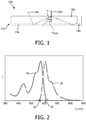
- Fig. 2 illustrates an absorption spectrum 26a and an emission spectrum 28a of an organic dye, Lumogen Red 305 (by BASF), used in the luminescent member 14a of the solar concentrator pursuant to Fig. 1 .
- a lower limit wavelength 30a of the emission spectrum 28a of about 570 nm is smaller than an upper limit wavelength 32a of about 610 nm of the absorption spectrum 26a of the organic dye, giving rise to re-absorption of luminescent light within the luminescent member 14a, which results in a loss of efficiency. More losses occur due to escape of luminescent light emitted at an angle ⁇ that is smaller than the critical angle ⁇ crit .
- Fig. 3 shows a photovoltaic generator 10b with a luminescent solar concentrator in accordance with an embodiment of the invention.
- the luminescent solar concentrator comprises a luminescent device 12b for converting incident light in an operating-ready mode.
- the luminescent device 12b comprises a nanostructured layer 34b and a luminescent member 14b which is in contact with and thereby in close proximity to the nanostructured layer 34b.
- Fig. 4 schematically illustrates an embodiment of a nanostructured layer 34b of the luminescent solar concentrator pursuant to Fig. 3 .
- a surface of a substrate is nanostructured, comprising a two-dimensional array of plasmonic nanoantennas 36b formed by metallic silver particles, the plasmonic nanoantennas 36b extending in an extension direction that is essentially perpendicular to a plane spanned by two array dimensions 38b, 40b.
- the metallic silver particles have a rounded rectangular shape.
- the array of plasmonic nanoantennas 36b is periodic in two directions that correspond to array dimensions 38b, 40b in that a nanoantenna 36b structure is repeated with a first pitch 42b of 550 nm in the first 38b of the two array dimensions 38b, 40b and with a second pitch 44b of 350 nm in the second 40b of the two array dimensions 38b, 40b.
- the array of nanoantennas 36b is in contact with a luminescent member 14b formed by a layer of cadmium selenide (CdSe)/cadmium sulfide (CdS) quantum dots.
- the layer of the luminescent member 14b has a thickness of 200 nm and is disposed on top of the array of nanoantennas 36b, parallel to the view plane of Fig. 4 .
- the array of nanoantennas 36b supports localized surface plasmon polaritons (LSPPs).
- LSPPs localized surface plasmon polaritons
- the incident light 16b that excites the luminescent member 14b can be resonant with the LSPPs, which allows for an enhancement of the excitation (pump enhancement) of the luminescent member 14b even with non-collimated light sources.
- An efficiency of the luminescent solar concentrator is further increased by coupling the incident light 16b to surface lattice resonances that arise from the diffractive coupling of individual LSPPs.
- the emission intensity I is resonantly increased and both a directionality and a polarization of the emission is controlled. Since the strength of the coupling depends on wavelength ⁇ and polarization, while a directionality of the emission closely resembles the angular dispersion of the surface lattice resonance, the emission characteristics like wavelength range, direction and polarization are determined by the design of the array of nanoantennas 36b.
- the absorption (pumping of the luminescent member 14b) can be tuned by changing the size and shape of the nanoparticles, whereas the emission of light can be tuned by changing a periodicity of the array.
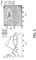
- Fig. 5 illustrates an angular distribution of light emission of a luminescent device 12b pursuant to Fig. 4 in two different views.
- the diagram to the left of Fig. 5 shows an emission enhancement f of light in dependence of an emission angle ⁇ for various wavelengths ⁇ .
- the emission enhancement f is defined as the emission of the quantum dots on top of the array of nanoantennas 36b normalized by the emission of quantum dots on top of a bare glass substrate, i.e. without the nanostructured layer 34b.
- the image to the right of Fig. 5 shows a contour plot of the emission enhancement f in dependence of the emission angle ⁇ and wavelength ⁇ .
- the luminescent device 12b is provided to maximally emit electromagnetic waves in the operation-ready mode for wavelengths ⁇ of about 630 nm at an angle ⁇ max that is larger than the critical angle ⁇ crit for total internal reflection of a light guide 18b.
- the emission of the quantum dots is enhanced for each wavelength ⁇ and each emission angle ⁇ .
- This overall emission enhancement f is the combined effect of an increase in both the pumping efficiency and the emission efficiency.
- the pump enhancement results from resonant scattering of the pump light by the nanoantennas 36b, since the frequency of the incident light 16b coincides with that of a localized surface plasmon resonance in the array.
- the emission enhancement f results from the coupling of the emitted light to surface lattice resonances and the coupling out of these modes to radiation.
- this invention can be applied with advantage in an embodiment comprising a luminescent device 12c with a nanostructured layer 34c pursuant to Fig. 4 and with a luminescent member 14c of the prior art luminescent solar concentrator pursuant to Fig. 1 .
- the nanostructured layer 34c in this case would be provided to enhance emission in a wavelength ⁇ range in which reabsorption by the luminescent member 14c could be avoided by having the emission spectrum 28c not overlapping the absorption spectrum 26c; i.e.
- a lower limit wavelength 30c of the emission spectrum 28c of electromagnetic waves of the nanostructured layer 34c to be larger than an upper limit wavelength 32c of the absorption spectrum 26c of electromagnetic waves of the luminescent member 14c, respresented by Lumogen Red 305.
- a wavelength ⁇ range of about 630 nm to 700 nm would be suitable to accomplish the desired effect.
- FIG. 6 A further embodiment of a luminescent device 12d for use in the luminescent solar concentrator pursuant to Fig. 3 is illustrated in Fig. 6 , showing an SEM (scanning electron micrograph) picture of a nanostructured layer 34d of the luminescent device 12d comprising an array of hetero-structured semiconductor nanowires 46d.
- SEM scanning electron micrograph
- Semiconductor nanowires 46d are grown standardly by chemical vapor deposition (CVD) techniques such as metal-organic vapor phase epitaxy (MOVPE) or molecular beam epitaxy (MBE) on crystalline substrates for epitaxial growth.
- CVD chemical vapor deposition
- MOVPE metal-organic vapor phase epitaxy
- MBE molecular beam epitaxy
- the growth of the nanowires 46d is catalyzed by a metal catalyst particle that defines the diameter of the nanowires 46d.
- the metal catalyst particle can be structured by substrate-conformal imprint lithography (SCIL) for fabricating ordered arrays of nanowires 46d.
- SCIL substrate-conformal imprint lithography
- Each one of the hetero-structured semiconductor nanowires 46d comprises a first section made from indium phosphide (InP) and a second, smaller section made from indium arsenide phosphide (InAsP) which functions as a luminescent member 14d.
- the two sections cannot be distinguished in the SEM image.
- the sections are arranged consecutively in a direction of extension 48d of the nanowires 46d.
- the array of hetero-structured semiconductor nanowires 46d has a periodic structure in two non-parallel directions that correspond to array dimensions 38d, 40d.
- the nanowires 46d are grown in a square lattice with pitches 42d, 44d of 513 nm.
- the top part 50d of the nanowires 46d is grown straight with a diameter of 90 nm and a length of 2 ⁇ m; the bottom part 52d is tapered with a length of 1 ⁇ m and a bottom diameter of 270 nm.
- Fig. 7 shows a photoluminescence plot of this array of InP nanowires as a function of emission angle ⁇ and wavelength ⁇ .
- the most interesting feature of the photoluminescence is the emission of the InAsP segment at wavelengths ⁇ > 900 nm.
- ⁇ max emission angle
- ⁇ wavelength of 956 nm
- the importance of the periodic structure on the emission profile is illustrated by calculating the Bloch modes of a photonic crystal composed of infinitely long non-absorbing cylinders with a diameter of 90 nm and a spacing of 513 nm for comparison.
- the white curve in Fig. 7 shows the calculated 2nd frequency band of the photonic crystal.
- the good agreement between the band structure calculation and the photoluminescence indicates the relevance of the periodic structure in the definition of the directional light emission.
- the agreement justifies the following explanation for the emission of the array:
- the photoexcited nanowires 46d and InAsP sections decay preferentially into natural oscillations ("eigenmodes") of the periodic structure, which are coupled at the interfaces to free space radiation.
Landscapes
- Physics & Mathematics (AREA)
- Health & Medical Sciences (AREA)
- Life Sciences & Earth Sciences (AREA)
- Sustainable Development (AREA)
- Toxicology (AREA)
- General Physics & Mathematics (AREA)
- Optics & Photonics (AREA)
- Photovoltaic Devices (AREA)
- Light Guides In General And Applications Therefor (AREA)
- Planar Illumination Modules (AREA)
Applications Claiming Priority (2)
| Application Number | Priority Date | Filing Date | Title |
|---|---|---|---|
| US201161579101P | 2011-12-22 | 2011-12-22 | |
| PCT/IB2012/057116 WO2013093696A2 (en) | 2011-12-22 | 2012-12-10 | Luminescent solar concentrator with nanostructured luminescent layer |
Publications (2)
| Publication Number | Publication Date |
|---|---|
| EP2748861A2 EP2748861A2 (en) | 2014-07-02 |
| EP2748861B1 true EP2748861B1 (en) | 2018-11-21 |
Family
ID=47624379
Family Applications (1)
| Application Number | Title | Priority Date | Filing Date |
|---|---|---|---|
| EP12819018.8A Not-in-force EP2748861B1 (en) | 2011-12-22 | 2012-12-10 | Luminescent solar concentrator with nanostructured luminescent layer |
Country Status (6)
Families Citing this family (6)
| Publication number | Priority date | Publication date | Assignee | Title |
|---|---|---|---|---|
| US10431706B2 (en) * | 2013-02-09 | 2019-10-01 | The Regents Of The University Of Michigan | Photoactive device |
| JP6381645B2 (ja) | 2013-08-06 | 2018-08-29 | コーニンクレッカ フィリップス エヌ ヴェKoninklijke Philips N.V. | 照明装置 |
| EP3251154A1 (en) | 2015-01-27 | 2017-12-06 | Eni S.p.A. | Hybrid concentrated photovoltaic device |
| US10340844B2 (en) | 2016-05-05 | 2019-07-02 | Washington State University | High-performance planar solar concentrators based on nanoparticle doping |
| US10804440B2 (en) | 2018-12-21 | 2020-10-13 | Lumileds Holding B.V. | Light extraction through adhesive layer between LED and converter |
| WO2022087355A1 (en) * | 2020-10-23 | 2022-04-28 | Oliveto Vincent James | Asymmetric light transmission surfaces for enhancing efficiency of solar concentrators |
Family Cites Families (10)
| Publication number | Priority date | Publication date | Assignee | Title |
|---|---|---|---|---|
| US20080149165A1 (en) * | 2006-12-22 | 2008-06-26 | General Electric Company | Luminescent solar collector |
| FR2914754B1 (fr) * | 2007-04-05 | 2009-07-17 | Commissariat Energie Atomique | Dispositif de concentration de lumiere plan a epaisseur reduite |
| IL193701A (en) * | 2008-08-26 | 2015-01-29 | Renata Reisfeld | Luminescent solar concentration |
| US20100126566A1 (en) * | 2008-11-21 | 2010-05-27 | Lightwave Power, Inc. | Surface plasmon wavelength converter |
| US20100126567A1 (en) * | 2008-11-21 | 2010-05-27 | Lightwave Power, Inc. | Surface plasmon energy conversion device |
| KR101562424B1 (ko) * | 2009-02-23 | 2015-10-21 | 이섬 리서치 디벨러프먼트 컴파니 오브 더 히브루 유니버시티 오브 예루살렘 엘티디. | 나노구조체를 사용하는 광학 디스플레이 장치 및 이의 방법 |
| WO2010118418A2 (en) | 2009-04-10 | 2010-10-14 | Lightwave Power, Inc. | Planar plasmonic device for light reflection, diffusion and guiding |
| US8933526B2 (en) * | 2009-07-15 | 2015-01-13 | First Solar, Inc. | Nanostructured functional coatings and devices |
| CN102473788B (zh) * | 2009-08-25 | 2016-03-30 | 皇家飞利浦电子股份有限公司 | 发光太阳能聚集器 |
| EP2510073B1 (en) * | 2009-12-08 | 2017-07-05 | Omnipv, Inc. | Luminescent materials that emit light in the visible range or the near infrared range and methods of forming thereof |
-
2012
- 2012-12-10 CN CN201280063853.9A patent/CN103999241B/zh not_active Expired - Fee Related
- 2012-12-10 US US14/366,335 patent/US20140311572A1/en not_active Abandoned
- 2012-12-10 WO PCT/IB2012/057116 patent/WO2013093696A2/en active Application Filing
- 2012-12-10 BR BR112014014977A patent/BR112014014977A8/pt not_active Application Discontinuation
- 2012-12-10 EP EP12819018.8A patent/EP2748861B1/en not_active Not-in-force
- 2012-12-10 JP JP2014548264A patent/JP6235484B2/ja not_active Expired - Fee Related
Non-Patent Citations (1)
| Title |
|---|
| None * |
Also Published As
| Publication number | Publication date |
|---|---|
| BR112014014977A2 (pt) | 2017-06-13 |
| WO2013093696A3 (en) | 2013-10-24 |
| JP2015507842A (ja) | 2015-03-12 |
| CN103999241B (zh) | 2017-11-07 |
| WO2013093696A2 (en) | 2013-06-27 |
| BR112014014977A8 (pt) | 2017-07-11 |
| EP2748861A2 (en) | 2014-07-02 |
| JP6235484B2 (ja) | 2017-11-22 |
| US20140311572A1 (en) | 2014-10-23 |
| CN103999241A (zh) | 2014-08-20 |
Similar Documents
| Publication | Publication Date | Title |
|---|---|---|
| EP2748861B1 (en) | Luminescent solar concentrator with nanostructured luminescent layer | |
| CN102396065B (zh) | 利用非辐射能量传递的光学元件 | |
| JP6577961B2 (ja) | プラズモン照明装置における光子エミッタの空間的位置決め | |
| Hua et al. | Efficient photon management with nanostructures for photovoltaics | |
| CN105409016B (zh) | 来自用于固态照明的等离子体耦合发射体的增强发射 | |
| US20090253227A1 (en) | Engineered or structured coatings for light manipulation in solar cells and other materials | |
| KR20160041997A (ko) | 이방성 방출을 위한 플라즈모닉 안테나 어레이를 갖는 고체 상태 조명 디바이스 | |
| US8416485B2 (en) | Designing the host of nano-structured optoelectronic devices to improve performance | |
| Zhu et al. | Effect of packing density and packing geometry on light extraction of III-nitride light-emitting diodes with microsphere arrays | |
| EP3188260A1 (en) | Nanostructure material structures and methods | |
| WO2016058828A1 (en) | Sideward emitting luminescent structures and illumination device comprising such luminescent structures | |
| Lv et al. | Enhanced absorptive characteristics of GaN nanowires for ultraviolet (UV) photocathode | |
| US20140102536A1 (en) | Composite Metallic Solar Cells | |
| Bailly et al. | 2D silver-nanoplatelets metasurface for bright directional photoluminescence, designed with the local Kirchhoff’s law | |
| JP6305873B2 (ja) | マイクロ構成を利用して表面プラズモンを形成する方法 | |
| Sheng et al. | Design and fabrication of high-index-contrast self-assembled texture for light extraction enhancement in LEDs | |
| Chauhan et al. | Broadband solar absorption with silicon metamaterials driven by strong proximity effects | |
| WO2015180970A1 (en) | Plasmonic-based illumination device | |
| Zeng et al. | Recent progress of metasurfaces in light-emitting diodes | |
| Sorias et al. | Epitaxial nanoflag photonics: semiconductor nanoemitters grown with their nanoantennas | |
| Ahmadi | Efficiency enhancement in thin-film silicon solar cells by plasmonic nanodiscs array | |
| US10873135B2 (en) | Antenna, assembly, and methods of forming the same | |
| AU2009100376A4 (en) | Engineered or structured coatings for light manipulation in solar cells and other materials | |
| Atwater | Bending light to our will | |
| Kim et al. | Transfer of a Well-Aligned TiO2 Nanorod Array onto GaN-Based LEDs for Light Extraction Enhancement |
Legal Events
| Date | Code | Title | Description |
|---|---|---|---|
| PUAI | Public reference made under article 153(3) epc to a published international application that has entered the european phase |
Free format text: ORIGINAL CODE: 0009012 |
|
| 17P | Request for examination filed |
Effective date: 20140326 |
|
| AK | Designated contracting states |
Kind code of ref document: A2 Designated state(s): AL AT BE BG CH CY CZ DE DK EE ES FI FR GB GR HR HU IE IS IT LI LT LU LV MC MK MT NL NO PL PT RO RS SE SI SK SM TR |
|
| DAX | Request for extension of the european patent (deleted) | ||
| 17Q | First examination report despatched |
Effective date: 20150612 |
|
| RAP1 | Party data changed (applicant data changed or rights of an application transferred) |
Owner name: PHILIPS LIGHTING HOLDING B.V. |
|
| RIN1 | Information on inventor provided before grant (corrected) |
Inventor name: DE BOER, DIRK KORNELIS GERHARDUS Inventor name: GOMEZ RIVAS, JAIME Inventor name: RAHIMZADEH KALALEH RODRIGUEZ, SAID Inventor name: DIEDENHOFEN, SILKE LUZIA |
|
| GRAP | Despatch of communication of intention to grant a patent |
Free format text: ORIGINAL CODE: EPIDOSNIGR1 |
|
| RIC1 | Information provided on ipc code assigned before grant |
Ipc: G02B 19/00 20060101ALI20180507BHEP Ipc: H01L 31/055 20140101AFI20180507BHEP |
|
| INTG | Intention to grant announced |
Effective date: 20180613 |
|
| GRAS | Grant fee paid |
Free format text: ORIGINAL CODE: EPIDOSNIGR3 |
|
| GRAA | (expected) grant |
Free format text: ORIGINAL CODE: 0009210 |
|
| AK | Designated contracting states |
Kind code of ref document: B1 Designated state(s): AL AT BE BG CH CY CZ DE DK EE ES FI FR GB GR HR HU IE IS IT LI LT LU LV MC MK MT NL NO PL PT RO RS SE SI SK SM TR |
|
| REG | Reference to a national code |
Ref country code: CH Ref legal event code: EP |
|
| RAP2 | Party data changed (patent owner data changed or rights of a patent transferred) |
Owner name: PHILIPS LIGHTING HOLDING B.V. |
|
| REG | Reference to a national code |
Ref country code: IE Ref legal event code: FG4D |
|
| REG | Reference to a national code |
Ref country code: DE Ref legal event code: R096 Ref document number: 602012053873 Country of ref document: DE |
|
| REG | Reference to a national code |
Ref country code: AT Ref legal event code: REF Ref document number: 1068550 Country of ref document: AT Kind code of ref document: T Effective date: 20181215 |
|
| PGFP | Annual fee paid to national office [announced via postgrant information from national office to epo] |
Ref country code: FR Payment date: 20181231 Year of fee payment: 7 Ref country code: GB Payment date: 20181221 Year of fee payment: 7 |
|
| RAP2 | Party data changed (patent owner data changed or rights of a patent transferred) |
Owner name: SIGNIFY HOLDING B.V. |
|
| REG | Reference to a national code |
Ref country code: NL Ref legal event code: MP Effective date: 20181121 |
|
| REG | Reference to a national code |
Ref country code: AT Ref legal event code: MK05 Ref document number: 1068550 Country of ref document: AT Kind code of ref document: T Effective date: 20181121 |
|
| PG25 | Lapsed in a contracting state [announced via postgrant information from national office to epo] |
Ref country code: FI Free format text: LAPSE BECAUSE OF FAILURE TO SUBMIT A TRANSLATION OF THE DESCRIPTION OR TO PAY THE FEE WITHIN THE PRESCRIBED TIME-LIMIT Effective date: 20181121 Ref country code: BG Free format text: LAPSE BECAUSE OF FAILURE TO SUBMIT A TRANSLATION OF THE DESCRIPTION OR TO PAY THE FEE WITHIN THE PRESCRIBED TIME-LIMIT Effective date: 20190221 Ref country code: NO Free format text: LAPSE BECAUSE OF FAILURE TO SUBMIT A TRANSLATION OF THE DESCRIPTION OR TO PAY THE FEE WITHIN THE PRESCRIBED TIME-LIMIT Effective date: 20190221 Ref country code: LT Free format text: LAPSE BECAUSE OF FAILURE TO SUBMIT A TRANSLATION OF THE DESCRIPTION OR TO PAY THE FEE WITHIN THE PRESCRIBED TIME-LIMIT Effective date: 20181121 Ref country code: IS Free format text: LAPSE BECAUSE OF FAILURE TO SUBMIT A TRANSLATION OF THE DESCRIPTION OR TO PAY THE FEE WITHIN THE PRESCRIBED TIME-LIMIT Effective date: 20190321 Ref country code: LV Free format text: LAPSE BECAUSE OF FAILURE TO SUBMIT A TRANSLATION OF THE DESCRIPTION OR TO PAY THE FEE WITHIN THE PRESCRIBED TIME-LIMIT Effective date: 20181121 Ref country code: ES Free format text: LAPSE BECAUSE OF FAILURE TO SUBMIT A TRANSLATION OF THE DESCRIPTION OR TO PAY THE FEE WITHIN THE PRESCRIBED TIME-LIMIT Effective date: 20181121 Ref country code: AT Free format text: LAPSE BECAUSE OF FAILURE TO SUBMIT A TRANSLATION OF THE DESCRIPTION OR TO PAY THE FEE WITHIN THE PRESCRIBED TIME-LIMIT Effective date: 20181121 Ref country code: HR Free format text: LAPSE BECAUSE OF FAILURE TO SUBMIT A TRANSLATION OF THE DESCRIPTION OR TO PAY THE FEE WITHIN THE PRESCRIBED TIME-LIMIT Effective date: 20181121 |
|
| PGFP | Annual fee paid to national office [announced via postgrant information from national office to epo] |
Ref country code: DE Payment date: 20190228 Year of fee payment: 7 |
|
| PG25 | Lapsed in a contracting state [announced via postgrant information from national office to epo] |
Ref country code: AL Free format text: LAPSE BECAUSE OF FAILURE TO SUBMIT A TRANSLATION OF THE DESCRIPTION OR TO PAY THE FEE WITHIN THE PRESCRIBED TIME-LIMIT Effective date: 20181121 Ref country code: SE Free format text: LAPSE BECAUSE OF FAILURE TO SUBMIT A TRANSLATION OF THE DESCRIPTION OR TO PAY THE FEE WITHIN THE PRESCRIBED TIME-LIMIT Effective date: 20181121 Ref country code: GR Free format text: LAPSE BECAUSE OF FAILURE TO SUBMIT A TRANSLATION OF THE DESCRIPTION OR TO PAY THE FEE WITHIN THE PRESCRIBED TIME-LIMIT Effective date: 20190222 Ref country code: RS Free format text: LAPSE BECAUSE OF FAILURE TO SUBMIT A TRANSLATION OF THE DESCRIPTION OR TO PAY THE FEE WITHIN THE PRESCRIBED TIME-LIMIT Effective date: 20181121 Ref country code: NL Free format text: LAPSE BECAUSE OF FAILURE TO SUBMIT A TRANSLATION OF THE DESCRIPTION OR TO PAY THE FEE WITHIN THE PRESCRIBED TIME-LIMIT Effective date: 20181121 Ref country code: PT Free format text: LAPSE BECAUSE OF FAILURE TO SUBMIT A TRANSLATION OF THE DESCRIPTION OR TO PAY THE FEE WITHIN THE PRESCRIBED TIME-LIMIT Effective date: 20190321 |
|
| PG25 | Lapsed in a contracting state [announced via postgrant information from national office to epo] |
Ref country code: IT Free format text: LAPSE BECAUSE OF FAILURE TO SUBMIT A TRANSLATION OF THE DESCRIPTION OR TO PAY THE FEE WITHIN THE PRESCRIBED TIME-LIMIT Effective date: 20181121 Ref country code: DK Free format text: LAPSE BECAUSE OF FAILURE TO SUBMIT A TRANSLATION OF THE DESCRIPTION OR TO PAY THE FEE WITHIN THE PRESCRIBED TIME-LIMIT Effective date: 20181121 Ref country code: PL Free format text: LAPSE BECAUSE OF FAILURE TO SUBMIT A TRANSLATION OF THE DESCRIPTION OR TO PAY THE FEE WITHIN THE PRESCRIBED TIME-LIMIT Effective date: 20181121 Ref country code: CZ Free format text: LAPSE BECAUSE OF FAILURE TO SUBMIT A TRANSLATION OF THE DESCRIPTION OR TO PAY THE FEE WITHIN THE PRESCRIBED TIME-LIMIT Effective date: 20181121 |
|
| REG | Reference to a national code |
Ref country code: CH Ref legal event code: PL |
|
| REG | Reference to a national code |
Ref country code: DE Ref legal event code: R097 Ref document number: 602012053873 Country of ref document: DE |
|
| PG25 | Lapsed in a contracting state [announced via postgrant information from national office to epo] |
Ref country code: EE Free format text: LAPSE BECAUSE OF FAILURE TO SUBMIT A TRANSLATION OF THE DESCRIPTION OR TO PAY THE FEE WITHIN THE PRESCRIBED TIME-LIMIT Effective date: 20181121 Ref country code: SM Free format text: LAPSE BECAUSE OF FAILURE TO SUBMIT A TRANSLATION OF THE DESCRIPTION OR TO PAY THE FEE WITHIN THE PRESCRIBED TIME-LIMIT Effective date: 20181121 Ref country code: RO Free format text: LAPSE BECAUSE OF FAILURE TO SUBMIT A TRANSLATION OF THE DESCRIPTION OR TO PAY THE FEE WITHIN THE PRESCRIBED TIME-LIMIT Effective date: 20181121 Ref country code: LU Free format text: LAPSE BECAUSE OF NON-PAYMENT OF DUE FEES Effective date: 20181210 Ref country code: MC Free format text: LAPSE BECAUSE OF FAILURE TO SUBMIT A TRANSLATION OF THE DESCRIPTION OR TO PAY THE FEE WITHIN THE PRESCRIBED TIME-LIMIT Effective date: 20181121 Ref country code: SK Free format text: LAPSE BECAUSE OF FAILURE TO SUBMIT A TRANSLATION OF THE DESCRIPTION OR TO PAY THE FEE WITHIN THE PRESCRIBED TIME-LIMIT Effective date: 20181121 |
|
| REG | Reference to a national code |
Ref country code: IE Ref legal event code: MM4A |
|
| PLBE | No opposition filed within time limit |
Free format text: ORIGINAL CODE: 0009261 |
|
| STAA | Information on the status of an ep patent application or granted ep patent |
Free format text: STATUS: NO OPPOSITION FILED WITHIN TIME LIMIT |
|
| REG | Reference to a national code |
Ref country code: BE Ref legal event code: MM Effective date: 20181231 |
|
| 26N | No opposition filed |
Effective date: 20190822 |
|
| PG25 | Lapsed in a contracting state [announced via postgrant information from national office to epo] |
Ref country code: IE Free format text: LAPSE BECAUSE OF NON-PAYMENT OF DUE FEES Effective date: 20181210 Ref country code: SI Free format text: LAPSE BECAUSE OF FAILURE TO SUBMIT A TRANSLATION OF THE DESCRIPTION OR TO PAY THE FEE WITHIN THE PRESCRIBED TIME-LIMIT Effective date: 20181121 |
|
| PG25 | Lapsed in a contracting state [announced via postgrant information from national office to epo] |
Ref country code: BE Free format text: LAPSE BECAUSE OF NON-PAYMENT OF DUE FEES Effective date: 20181231 |
|
| PG25 | Lapsed in a contracting state [announced via postgrant information from national office to epo] |
Ref country code: LI Free format text: LAPSE BECAUSE OF NON-PAYMENT OF DUE FEES Effective date: 20181231 Ref country code: CH Free format text: LAPSE BECAUSE OF NON-PAYMENT OF DUE FEES Effective date: 20181231 |
|
| PG25 | Lapsed in a contracting state [announced via postgrant information from national office to epo] |
Ref country code: MT Free format text: LAPSE BECAUSE OF NON-PAYMENT OF DUE FEES Effective date: 20181210 |
|
| PG25 | Lapsed in a contracting state [announced via postgrant information from national office to epo] |
Ref country code: TR Free format text: LAPSE BECAUSE OF FAILURE TO SUBMIT A TRANSLATION OF THE DESCRIPTION OR TO PAY THE FEE WITHIN THE PRESCRIBED TIME-LIMIT Effective date: 20181121 |
|
| PG25 | Lapsed in a contracting state [announced via postgrant information from national office to epo] |
Ref country code: HU Free format text: LAPSE BECAUSE OF FAILURE TO SUBMIT A TRANSLATION OF THE DESCRIPTION OR TO PAY THE FEE WITHIN THE PRESCRIBED TIME-LIMIT; INVALID AB INITIO Effective date: 20121210 Ref country code: MK Free format text: LAPSE BECAUSE OF NON-PAYMENT OF DUE FEES Effective date: 20181121 Ref country code: CY Free format text: LAPSE BECAUSE OF FAILURE TO SUBMIT A TRANSLATION OF THE DESCRIPTION OR TO PAY THE FEE WITHIN THE PRESCRIBED TIME-LIMIT Effective date: 20181121 |
|
| REG | Reference to a national code |
Ref country code: DE Ref legal event code: R119 Ref document number: 602012053873 Country of ref document: DE |
|
| GBPC | Gb: european patent ceased through non-payment of renewal fee |
Effective date: 20191210 |
|
| PG25 | Lapsed in a contracting state [announced via postgrant information from national office to epo] |
Ref country code: FR Free format text: LAPSE BECAUSE OF NON-PAYMENT OF DUE FEES Effective date: 20191231 Ref country code: GB Free format text: LAPSE BECAUSE OF NON-PAYMENT OF DUE FEES Effective date: 20191210 Ref country code: DE Free format text: LAPSE BECAUSE OF NON-PAYMENT OF DUE FEES Effective date: 20200701 |