EP2748060B1 - Method and device for averting and damping rolling of a ship - Google Patents
Method and device for averting and damping rolling of a ship Download PDFInfo
- Publication number
- EP2748060B1 EP2748060B1 EP12831107.3A EP12831107A EP2748060B1 EP 2748060 B1 EP2748060 B1 EP 2748060B1 EP 12831107 A EP12831107 A EP 12831107A EP 2748060 B1 EP2748060 B1 EP 2748060B1
- Authority
- EP
- European Patent Office
- Prior art keywords
- ship
- rolling
- engine
- speed
- propeller
- Prior art date
- Legal status (The legal status is an assumption and is not a legal conclusion. Google has not performed a legal analysis and makes no representation as to the accuracy of the status listed.)
- Not-in-force
Links
Images




Classifications
-
- G—PHYSICS
- G05—CONTROLLING; REGULATING
- G05D—SYSTEMS FOR CONTROLLING OR REGULATING NON-ELECTRIC VARIABLES
- G05D1/00—Control of position, course, altitude or attitude of land, water, air or space vehicles, e.g. using automatic pilots
- G05D1/40—Control within particular dimensions
- G05D1/49—Control of attitude, i.e. control of roll, pitch or yaw
-
- B—PERFORMING OPERATIONS; TRANSPORTING
- B63—SHIPS OR OTHER WATERBORNE VESSELS; RELATED EQUIPMENT
- B63B—SHIPS OR OTHER WATERBORNE VESSELS; EQUIPMENT FOR SHIPPING
- B63B39/00—Equipment to decrease pitch, roll, or like unwanted vessel movements; Apparatus for indicating vessel attitude
-
- B—PERFORMING OPERATIONS; TRANSPORTING
- B63—SHIPS OR OTHER WATERBORNE VESSELS; RELATED EQUIPMENT
- B63B—SHIPS OR OTHER WATERBORNE VESSELS; EQUIPMENT FOR SHIPPING
- B63B39/00—Equipment to decrease pitch, roll, or like unwanted vessel movements; Apparatus for indicating vessel attitude
- B63B39/08—Equipment to decrease pitch, roll, or like unwanted vessel movements; Apparatus for indicating vessel attitude to decrease vessel movements by using auxiliary jets or propellers
-
- B—PERFORMING OPERATIONS; TRANSPORTING
- B63—SHIPS OR OTHER WATERBORNE VESSELS; RELATED EQUIPMENT
- B63B—SHIPS OR OTHER WATERBORNE VESSELS; EQUIPMENT FOR SHIPPING
- B63B39/00—Equipment to decrease pitch, roll, or like unwanted vessel movements; Apparatus for indicating vessel attitude
- B63B39/14—Equipment to decrease pitch, roll, or like unwanted vessel movements; Apparatus for indicating vessel attitude for indicating inclination or duration of roll
-
- B—PERFORMING OPERATIONS; TRANSPORTING
- B63—SHIPS OR OTHER WATERBORNE VESSELS; RELATED EQUIPMENT
- B63H—MARINE PROPULSION OR STEERING
- B63H21/00—Use of propulsion power plant or units on vessels
- B63H21/21—Control means for engine or transmission, specially adapted for use on marine vessels
-
- G—PHYSICS
- G05—CONTROLLING; REGULATING
- G05D—SYSTEMS FOR CONTROLLING OR REGULATING NON-ELECTRIC VARIABLES
- G05D1/00—Control of position, course, altitude or attitude of land, water, air or space vehicles, e.g. using automatic pilots
- G05D1/40—Control within particular dimensions
- G05D1/49—Control of attitude, i.e. control of roll, pitch or yaw
- G05D1/495—Control of attitude, i.e. control of roll, pitch or yaw to ensure stability
-
- G—PHYSICS
- G05—CONTROLLING; REGULATING
- G05D—SYSTEMS FOR CONTROLLING OR REGULATING NON-ELECTRIC VARIABLES
- G05D2109/00—Types of controlled vehicles
- G05D2109/30—Water vehicles
-
- G—PHYSICS
- G05—CONTROLLING; REGULATING
- G05D—SYSTEMS FOR CONTROLLING OR REGULATING NON-ELECTRIC VARIABLES
- G05D2109/00—Types of controlled vehicles
- G05D2109/30—Water vehicles
- G05D2109/34—Water vehicles operating on the water surface
Definitions
- This invention relates to a method and a device for averting and damping rolling of an engine-driven marine vessel with propeller propulsion.
- Rolling of ships is a well-known risk to ship's safety. It can lead to loss of containers, high stress on the cargo securing system and discomfort for passengers and crew. Rolling of a ship can be described as the periodic movement of a pendulum. The corresponding time period is called the "natural rolling period" of a ship.
- the corresponding time period is called the "natural rolling period" of a ship.
- the pendulum-type of rolling will dampen quickly due to the restoring moment and due to friction forces between the ship's hull and water.
- Rolling may be triggered by environmental disturbances such as waves, wind or sea currents.
- disturbances can have very low energy and still develop successively into a high-amplitude rolling by an energy transfer mechanism between two states.
- a known dangerous variant of a critical rolling is the so called "parametric rolling", emerging when sea waves along the ship have a period that matches in a certain relation a ship's natural period.
- a rolling with maintained amplitude and constant period is called a "critical rolling”.
- PA1 anti-rolling methods and devices
- PA2 engine speed and load control devices
- Passive anti-rolling devices such as bilge keels are using friction energy to dissipate the rolling energy of a ship. Active anti-rolling devices are more effective than passive devices due to specialized actuators manipulated by controllers that inject energy to counteract rolling forces. Often used contemporary anti-rolling actuators are fin stabilizers.
- Two patents that describe active anti-rolling devices are the European patent PA0423901A1 and the US patent US20080183341A1 .
- the first uses as anti-rolling actuators the propulsion machinery of the ship consisting of controllable water jet engines and the later uses as anti-rolling actuators the torque difference between two propellers or two groups of propellers that are also used for the propulsion of the ship.
- the ship's Speed and Load Control Device has the purpose to keep the ship's engine speed and load within given operational range. Consequently, the ship's speed can also be maintained within a given range.
- FIG. 2 shows schematically the components of a traditional speed and load control device for a diesel engine.
- a speed-set device 300 is used to set the required engine speed at a value n *. Typically an operator or an automated navigation system provides the speed set value.
- the actual speed of the engine n is read by a rotation speed sensor 314 .
- the speed comparator 302 subtracts the rotation speed of the engine from the set speed.
- the resulting speed difference dn is applied to a Speed Controller 304.
- the output from the speed Controller is the set-point p * to a Fuel Device 310 .
- a fuel pump comparator 306 subtracts the actual fuel injection level p read by the Fuel Injection Pump Index Sensor 312 from the set-point value p *.
- the resulting difference dp is the input to the Fuel Controller 308 that manipulates the fuel device 310 via a power signal fc .
- the Fuel Device commands the fuel injection into the diesel engine 316 such that the engine speed n will be kept close to the set-point value n *.
- the fuel device is a mechanical actuator while for a Common Rail Fuel system the fuel device is the Electronic Control Unit of the engine.
- Propulsion arrangements with diesel-electric engines work in the same fashion but with the difference that electrical generators and electrical motors are placed between the diesel engine and the propeller and it is the electrical motor that is speed-controlled.
- the arrangement improves the prior art PA2 described earlier to incorporate additionally the roll averting and damping functionality.
- a marine vessel may comprise a plurality of engines and propellers. For simplicity, only one engine and one propeller are described in this embodiment.
- the arrangement according to this preferred embodiment essentially comprises the Roll Averting and Damping Device 320 (the RAD device) that can intervene with an overriding command to the Speed and Load Control Device 334 of the ship.
- Inputs to the RAD device comprises: (1) sampled signals from one or several sensors that are used to evaluate rolling properties of the ship and (2) information about technical and physical properties of different devices in the arrangement.
- the outputs from the RAD device are overriding commands and parameters to the Speed and Load Control Device 334 that alter the normal, prior art function of the said device 334 .
- Overriding commands can be applied to any of the following subparts of the device 334 : the Speed Comparator 302 , the Speed Controller 304 or the Fuel Controller 308 . All these subparts can achieve a change on the engine speed.
- the overriding commands are applied to the Speed Controller 304 .
- the RAD device can be advantageously integrated with the Speed Controller 304 .
- the sensor used to determine rolling properties is an inclinometer 322 that gives the ship's current heel angle ⁇ .
- Information about ship properties is given via an operator's interface and/or via a superior computer 324.
- Properties of interest comprise ship's natural period Ts , transversal inertial moment Js and ship's rolling damping coefficient ⁇ s .
- Engine properties of interest comprise engine power Pe, nominal speed Nn , and the inertial moment of the engine Je.
- Properties of interest for the speed and load control device are the control amplification factor k and the time constants for the fuel device and controller Tc . In the preferred embodiment, this information is assumed known from technical specifications or from ship commissioning tests.
- the RAD device needs a dynamic model of the ship and values for parameters of this dynamic model as described in the preferred embodiment section.
- Ship dynamic models and parameter values can be determined by system identification methods, using sensor values. Control engineers skilled in the art are commonly using such methods.
- the overriding command from the RAD device is applied to the Speed Controller 304.
- a similar effect on the engine speed can be achieved by applying an overriding command to the Fuel Controller 308 or to the speed comparator 302. All these alternatives are essentially variations using the same disclosed principle of breaking a critical interaction between the speed control function of the engine and rolling, as described in the Algorithm section.
- the method steps for the preferred embodiment disclosed in Figure 4 are performed repeatedly at a constant time interval Tsample to ensure a relevant number of sensor readings for each rolling time period.
- An appropriate range for Tsample would be from tenths to hundreds of milliseconds.
- Typical rolling periods are 10 to 30 seconds.
- Step 1 The RAD device 320 is reading the inclinometer 322 to get the current heel angle of the ship ⁇ . This value is stored in the RAD device and is available for further computations.
- Step 2 Using past heel angle readings, the RAD device determines the amplitude Ar and time period Tr of the ship's rolling.
- Step 3 the RAD device determines the trend of the rolling amplitude and rolling period over an interval Ttrend (the trend time).
- Ttrend the trend time.
- the trend time the ship undergoes several rolling periods whose amplitude and period trends are characterized as follows.
- the trend for the amplitude Ar is characterised as being one of the following categories: Low, Stochastic, Constant, Increasing or Decreasing.
- the trend for the rolling period Tr is characterized by being one of the following kinds: Stochastic, Constant or Natural.
- Stochastic' means that the roll period Tr , respectively the amplitude Ar are not regular.
- Constant' means a rolling time that is stable at a value that is different from the ship's natural rolling time.
- 'Natural' means that rolling has the rolling period value equal to the natural rolling time.
- 'Low' means that the amplitude of rolling is low.
- Step 4 The RAD device 320 uses the trends determined at Step 3 together with the ship's dynamic properties and engine properties to determine an overriding command on the speed and load control device that is effectively averting and damping rolling and which also maintains the set speed of the ship.
- the prior art speed control algorithm that has no roll damping is denoted here as NS.
- the preferred embodiment defines two kinds of algorithms that are averting or damping ship's rolling: (1) constant speed ( CS ) and inverted control ( IC ).
- IC has a stronger roll reducing effect as compared to CS , so it might be applied for stronger rolling.
- the preferred embodiment discloses a set of rules for algorithm selection of the roll reducing and damping type as shown in Table 1.
- the rolling amplitude is 'Low' or the speed error dn is large, then the rule NS (normal, prior art) speed control is applied. If the Roll Period is 'Constant' (second row) and the Roll Amplitude is 'Increase' (the fifth line), the stronger rule IC (inverted control) is applied to damp the increasing rolling.
- the CS constant speed algorithm is applied.
- the other cells of the table are interpreted in the same fashion, thus an appropriate roll damping and averting algorithm is selected for appropriate conditions.
- rolling is persistent, e.g. due to sea conditions, then the CS and IS rules will be applied more often than NS.
- the propeller and hence the ship will not keep a constant, predefined speed.
- the speed error dn will increase and after a time the rules in the first line of the table will trigger a normal speed control NS that will bring the speed to the predefined value.
- An alternative method is to trigger NS rules at constant time intervals to avoid large speed deviations.
- Step 5 the RAD device 320 is activating the selected algorithm as an overriding command to the Speed and Load Control Device 334.
- This overriding command modifies the normal function of the speed controller to avert rolling.
- the speed controller determines the output torque of the engine.
- the torque increases or decreases depending on (a) the ship's speed, (b) the rotation speed of the propeller, (c) variations of the ship's heel angle, (d) rudder interaction with the water stream produced by the propeller, (e) changes in ship's yaw angle and (f) interaction between waves and hull.
- the torque from the engine is converted mainly to a longitudinal thrust; however a small portion is creating a moment and reaction moment between the propeller and the surrounding water. This torque is transferred from the propeller to the ship's hull.
- the torque is proportional to the engine power. Higher ship speed means a higher torque on the propeller, by a near quadratic relation.
- the speed sensor 314 registers a reduction in RPM.
- the speed controller 304 will increase the moment on the engine to restore the speed. This will increase the uneven water flow such that the ship will tend to change heading. This will further increase the heel angle sensed by the inclinometer 322 and consequently the moment on the engine will increase again, in a continuous process until equilibrium is reached via compensating restore- and friction moments.
- the moment of the engine will increase non-linearly with the heel angle. This non-linearity, described by a near quadratic function, will maintain a self-sustained rolling. This effect appears for both single and multi-propeller ships.
- the vessel dynamics in calm water is different compared to a rough sea condition when the attack angle of the wave on the ship's hull must be taken into consideration.
- the engine-propeller unit In calm water conditions, the engine-propeller unit has a steady rotational speed.
- the rudder is in mid position and the torque lists the vessel, opposite to the direction of the propeller rotation.
- the list angle is typically in the range 0.5 - 2 degrees.
- the angular velocity of the heel angle is zero.
- the hull transverse angle and angular velocity increases or decreases the engine load:
- This variation is superimposed on the load variation originating from the ship's speed variation.
- the rotation speed and load of the engine, hence the torque, become variable.
- the variation of load causes the engine speed controller to increase or decrease the fuel index 312 to maintain the required rotational speed.
- the attacking waves lead to a heading error.
- the heading controller of the autopilot then changes the rudder position to correct the heading error. Corrections done by the heading control system can also increase or decrease the heel angle and thus the engine load.
- the rolling of propulsion driven ships can be determined by solving a system of equations modelling the heel angle dynamics as the interaction between speed control, engine torque and ship's inertial forces.
- E1 consists of the following terms:
- the core of the proposed roll averting and damping method is avoiding the build-up of rolling by manipulating the speed control parameters appearing on the right side of the differential equation such that the heel angle acceleration, speed and value is effectively reduced.
- rolling will dampen quickly due to the restoring moment and due to friction forces between the ship's hull and the water.
- the resulting reduction in propeller torque variation means less propeller slip and less fuel consumption.
- the proposed method comprises, but is not limited to one of the following alternatives:
- the preferred embodiment described by the method steps shown in Figure 4 discloses two roll damping and reducing methods: the constant speed algorithm (CS) that can be implemented by the methods M1 or M2 described above and the inverted control (IC) that can be implemented as algorithm M3, M4 or M5.
- CS constant speed algorithm
- IC inverted control
Landscapes
- Engineering & Computer Science (AREA)
- Chemical & Material Sciences (AREA)
- Ocean & Marine Engineering (AREA)
- Mechanical Engineering (AREA)
- Combustion & Propulsion (AREA)
- Physics & Mathematics (AREA)
- Automation & Control Theory (AREA)
- General Physics & Mathematics (AREA)
- Remote Sensing (AREA)
- Radar, Positioning & Navigation (AREA)
- Aviation & Aerospace Engineering (AREA)
- Feedback Control In General (AREA)
- Control Of Vehicle Engines Or Engines For Specific Uses (AREA)
- Control Of Position, Course, Altitude, Or Attitude Of Moving Bodies (AREA)
- Output Control And Ontrol Of Special Type Engine (AREA)
- Combined Controls Of Internal Combustion Engines (AREA)
- Vibration Prevention Devices (AREA)
Description
- This invention relates to a method and a device for averting and damping rolling of an engine-driven marine vessel with propeller propulsion.
- Rolling of ships is a well-known risk to ship's safety. It can lead to loss of containers, high stress on the cargo securing system and discomfort for passengers and crew. Rolling of a ship can be described as the periodic movement of a pendulum. The corresponding time period is called the "natural rolling period" of a ship. When a ship is tilted e.g. by a sea wave, the centre of buoyancy of the ship moves laterally and a restoring moment is created which re-stabilizes the ship.
- Most often, the pendulum-type of rolling will dampen quickly due to the restoring moment and due to friction forces between the ship's hull and water. Rolling may be triggered by environmental disturbances such as waves, wind or sea currents. In some cases, disturbances can have very low energy and still develop successively into a high-amplitude rolling by an energy transfer mechanism between two states. For example a known dangerous variant of a critical rolling is the so called "parametric rolling", emerging when sea waves along the ship have a period that matches in a certain relation a ship's natural period.
- A rolling with maintained amplitude and constant period is called a "critical rolling".
- Historically, different types of devices have been proposed to reduce rolling, such as bilge keels, fin stabilizers or rudder movements. However, rolling is still a major problem for ship navigation.
- For better understanding of the described method, reference will be made to the following figures.
-
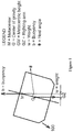
Figure 1 Illustrates restoring forces and the restore moment of a tilted ship -
Figure 2 Illustrates a typical configuration (background-art) of a ship's speed control with associated actuators and sensors -
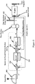
Figure 3 Illustrates schematically the configuration of a rolling averting and damping arrangement according to an exemplified embodiment -
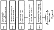
Figure 4 Illustrates a flow chart for the different method steps for roll damping and averting of a ship according to a preferred embodiment -
Figure 5 Illustrates a ship's critical rolling when the roll averting and damping device is not active -
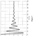
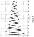
Figures 6 ,7 ,8 ,9 ,10 illustrate examples of roll damping responses according to various exemplifying embodiments of the roll averting and damping principle - The following prior-art is referred to in this document: (PA1): anti-rolling methods and devices, (PA2): engine speed and load control devices.
- Passive anti-rolling devices such as bilge keels are using friction energy to dissipate the rolling energy of a ship. Active anti-rolling devices are more effective than passive devices due to specialized actuators manipulated by controllers that inject energy to counteract rolling forces. Often used contemporary anti-rolling actuators are fin stabilizers.
- An automated rolling reduction method, is presented by the
US patent of H.H. Dow No. 1,731,236, October 15, 1929 and No.1774, 825 September 2, 1930 (the Dow patents). The Dow patents describe the use of a propeller or two propellers as anti-rolling actuators by counterbalancing the heel angle of a ship using the moment of one propeller or the resulting moment created between two propellers. Furthermore, the patent describes a mechanical setup for this compensation, an embodiment of a control system realized with the technology of 1930s, - Two patents that describe active anti-rolling devices are the European patent
PA0423901A1 US20080183341A1 . The first uses as anti-rolling actuators the propulsion machinery of the ship consisting of controllable water jet engines and the later uses as anti-rolling actuators the torque difference between two propellers or two groups of propellers that are also used for the propulsion of the ship. - The ship's Speed and Load Control Device has the purpose to keep the ship's engine speed and load within given operational range. Consequently, the ship's speed can also be maintained within a given range.
-
Figure 2 shows schematically the components of a traditional speed and load control device for a diesel engine. A speed-set device 300 is used to set the required engine speed at a value n*. Typically an operator or an automated navigation system provides the speed set value. The actual speed of the engine n is read by arotation speed sensor 314. Thespeed comparator 302 subtracts the rotation speed of the engine from the set speed. The resulting speed difference dn is applied to aSpeed Controller 304. The output from the speed Controller is the set-point p* to aFuel Device 310. Afuel pump comparator 306 subtracts the actual fuel injection level p read by the Fuel InjectionPump Index Sensor 312 from the set-point value p*. The resulting difference dp is the input to theFuel Controller 308 that manipulates thefuel device 310 via a power signal fc. The Fuel Device commands the fuel injection into thediesel engine 316 such that the engine speed n will be kept close to the set-point value n*. For most diesel engines the fuel device is a mechanical actuator while for a Common Rail Fuel system the fuel device is the Electronic Control Unit of the engine. Propulsion arrangements with diesel-electric engines work in the same fashion but with the difference that electrical generators and electrical motors are placed between the diesel engine and the propeller and it is the electrical motor that is speed-controlled. - An arrangement and a method for averting and damping the roll of a propeller-driven vessel are hereby described according to a preferred embodiment. The method and the associated arrangement are supported by a mathematical formalism, described in the Algorithm section, that considers the physics involved in the rolling of a vessel.
- As disclosed in
Figure 3 , the arrangement improves the prior art PA2 described earlier to incorporate additionally the roll averting and damping functionality. - A marine vessel may comprise a plurality of engines and propellers. For simplicity, only one engine and one propeller are described in this embodiment.
- The arrangement according to this preferred embodiment essentially comprises the Roll Averting and Damping Device 320 (the RAD device) that can intervene with an overriding command to the Speed and
Load Control Device 334 of the ship. Inputs to the RAD device comprises: (1) sampled signals from one or several sensors that are used to evaluate rolling properties of the ship and (2) information about technical and physical properties of different devices in the arrangement. The outputs from the RAD device are overriding commands and parameters to the Speed andLoad Control Device 334 that alter the normal, prior art function of thesaid device 334. Overriding commands can be applied to any of the following subparts of the device 334: the Speed Comparator 302, the SpeedController 304 or theFuel Controller 308. All these subparts can achieve a change on the engine speed. In the preferred embodiment, the overriding commands are applied to theSpeed Controller 304. Practically, the RAD device can be advantageously integrated with the SpeedController 304. - In this preferred embodiment, the sensor used to determine rolling properties is an
inclinometer 322 that gives the ship's current heel angle θ. - Information about ship properties is given via an operator's interface and/or via a
superior computer 324. Properties of interest comprise ship's natural period Ts, transversal inertial moment Js and ship's rolling damping coefficient ζs . Engine properties of interest comprise engine power Pe, nominal speed Nn, and the inertial moment of the engine Je. Properties of interest for the speed and load control device are the control amplification factor k and the time constants for the fuel device and controller Tc. In the preferred embodiment, this information is assumed known from technical specifications or from ship commissioning tests. - The RAD device needs a dynamic model of the ship and values for parameters of this dynamic model as described in the preferred embodiment section. Ship dynamic models and parameter values can be determined by system identification methods, using sensor values. Control engineers skilled in the art are commonly using such methods.
- In the preferred embodiment, the overriding command from the RAD device is applied to the
Speed Controller 304. In an alternative embodiment a similar effect on the engine speed can be achieved by applying an overriding command to theFuel Controller 308 or to thespeed comparator 302. All these alternatives are essentially variations using the same disclosed principle of breaking a critical interaction between the speed control function of the engine and rolling, as described in the Algorithm section. - The method steps for the preferred embodiment disclosed in
Figure 4 are performed repeatedly at a constant time interval Tsample to ensure a relevant number of sensor readings for each rolling time period. An appropriate range for Tsample would be from tenths to hundreds of milliseconds. Typical rolling periods are 10 to 30 seconds. -
Step 1. TheRAD device 320 is reading theinclinometer 322 to get the current heel angle of the ship θ. This value is stored in the RAD device and is available for further computations. -
Step 2. Using past heel angle readings, the RAD device determines the amplitude Ar and time period Tr of the ship's rolling. There are many known methods to determine the amplitude and period of the principal sine wave component of a sampled signal such as discrete Fourier transform, curve fitting or zero-crossing. In the preferred embodiment, a zero-crossing algorithm is proposed as follows: the RAD device uses a set of heel angle samples taken during a time interval equal to ship's natural period and determines the maximum past heel angle, Hmax, and the minimum past heel angle Hmin in the set of sampled values. The time interval between two consecutive zero-crossing heel angle changes is also measured as Tzero. Then the rolling amplitude Ar is computed as Ar=(Hmax-Hmin) /2 and the rolling period Tr as Tr=2*Tzero. -
Step 3. At this method step, the RAD device determines the trend of the rolling amplitude and rolling period over an interval Ttrend (the trend time). The magnitude of Ttrend depends on the type of the ship and on the speed precision requirement. An appropriate value is a small multiple of the ship's natural rolling period. For example if the ship's natural rolling period is Ts = 20 seconds, then a proper range for Ttrend might be between 20 to 200 seconds. During the trend time, the ship undergoes several rolling periods whose amplitude and period trends are characterized as follows. The trend for the amplitude Ar is characterised as being one of the following categories: Low, Stochastic, Constant, Increasing or Decreasing. The trend for the rolling period Tr is characterized by being one of the following kinds: Stochastic, Constant or Natural. 'Stochastic' means that the roll period Tr, respectively the amplitude Ar are not regular. 'Constant' means a rolling time that is stable at a value that is different from the ship's natural rolling time. 'Natural' means that rolling has the rolling period value equal to the natural rolling time. 'Low' means that the amplitude of rolling is low. The trends described above are for the preferred embodiment. Alternative embodiments may have trend characterization different from the preferred embodiment, such as more types of intervals or a continuous range. -
Step 4. TheRAD device 320 uses the trends determined atStep 3 together with the ship's dynamic properties and engine properties to determine an overriding command on the speed and load control device that is effectively averting and damping rolling and which also maintains the set speed of the ship. The prior art speed control algorithm that has no roll damping is denoted here as NS. As described further in the Algorithm section, the preferred embodiment defines two kinds of algorithms that are averting or damping ship's rolling: (1) constant speed (CS) and inverted control (IC). IC has a stronger roll reducing effect as compared to CS, so it might be applied for stronger rolling. The preferred embodiment discloses a set of rules for algorithm selection of the roll reducing and damping type as shown in Table 1. For example, as seen in the first line of the table, if the rolling amplitude is 'Low' or the speed error dn is large, then the rule NS (normal, prior art) speed control is applied. If the Roll Period is 'Constant' (second row) and the Roll Amplitude is 'Increase' (the fifth line), the stronger rule IC (inverted control) is applied to damp the increasing rolling.
- If the Roll Period is stochastic (second column) and the amplitude has a decreasing trend (fourth line) then the CS constant speed algorithm is applied. The other cells of the table are interpreted in the same fashion, thus an appropriate roll damping and averting algorithm is selected for appropriate conditions. If rolling is persistent, e.g. due to sea conditions, then the CS and IS rules will be applied more often than NS. As a result, the propeller and hence the ship will not keep a constant, predefined speed. Thus the speed error dn will increase and after a time the rules in the first line of the table will trigger a normal speed control NS that will bring the speed to the predefined value. An alternative method is to trigger NS rules at constant time intervals to avoid large speed deviations.
-
Step 5. At this method step, theRAD device 320 is activating the selected algorithm as an overriding command to the Speed andLoad Control Device 334. This overriding command modifies the normal function of the speed controller to avert rolling. - Finally, the method steps are applied again at the next Tsample time starting from
Step 1. - The steps described above might be varied in alternative embodiments as follows:
- A sensor may measure the heel angle θ and the first and second derivatives of θ at
Step 1, such thatStep 2 can make a more accurate evaluation of the rolling amplitude and rolling period. -
Step - At
Step 3 the rolling trend might be better predicted by using information on rudder position and ship's pitch angle. - At
Step 4, only one, two or several rolling averting and damping algorithms may be used. - At
step 4, depending on the ship's type and on roll damping preferences, other rule-based methods or continuous interval methods might be used in alternative embodiments as long as the roll averting principle described in the Algorithm section is followed. - At
step 5, the overriding command can be applied with the same effect on thespeed comparator 302, on theSpeed Controller 304 or on theFuel Controller 308. The preferred embodiment is to integrate the RAD device into theSpeed Controller 304. - Ship rolling is a combined result of many forces such as:
- The engine torque
- The ship's hull interaction with the water
- The propeller interaction with the water
- The rudder interaction with the water stream
- Some of the explanations that follow are for vessels with one propeller and some for vessels with two or several propellers. For vessels with several propellers and for azimuth propellers, it is assumed that each propeller has its own speed control system.
- The speed controller determines the output torque of the engine. The torque increases or decreases depending on (a) the ship's speed, (b) the rotation speed of the propeller, (c) variations of the ship's heel angle, (d) rudder interaction with the water stream produced by the propeller, (e) changes in ship's yaw angle and (f) interaction between waves and hull.
- The below described phenomena, individual or combined are contributing to the development of critical rolling that can be described as a correlation between controller dynamics, ship's specific rolling period and wave dynamics. The condition is a driven harmonic oscillation.
- The torque from the engine is converted mainly to a longitudinal thrust; however a small portion is creating a moment and reaction moment between the propeller and the surrounding water. This torque is transferred from the propeller to the ship's hull. The torque is proportional to the engine power. Higher ship speed means a higher torque on the propeller, by a near quadratic relation.
- When the ship is heeling the propeller becomes located offside from the ship's centerline. This gives the propeller trust a moment arm that turns the ship in the same direction as the heel. Thus, while rolling, the ship will have successively a port to starboard and starboard to port-curved trajectory.
- For a ship having zero heel angle, the water flows symmetrically on both the STB and Port side. A heeled ship has an uneven flow of water around the hull. According to the Bernoulli principle, the pressures on the STB and Port side will be different. An inclined ship has hydrodynamic properties that are inferior compared to a ship on even keel.
- The result is more drag causing the ship's speed to decrease and the propeller torque to increase. The
speed sensor 314 registers a reduction in RPM. Thespeed controller 304 will increase the moment on the engine to restore the speed. This will increase the uneven water flow such that the ship will tend to change heading. This will further increase the heel angle sensed by theinclinometer 322 and consequently the moment on the engine will increase again, in a continuous process until equilibrium is reached via compensating restore- and friction moments. The moment of the engine will increase non-linearly with the heel angle. This non-linearity, described by a near quadratic function, will maintain a self-sustained rolling. This effect appears for both single and multi-propeller ships. - The literature on ship handling describes a number of effects creating aft lateral movements due to uneven flow of water through the propeller blades: following wake effect, inclination effect and helical discharge effect. These effects follow from differences in water flow through the STB and Port side of a ship's propeller. Aft lateral movement is creating a heading change, which creates a transversal centripetal force that increases the heel angle. These effects appear only for a single propeller ship.
- Rolling moment created by the changes in heading (turning) of a ship. A ship with mass m that has a linear speed v, has a kinetic energy expressed by Ek = mv 2/2. A ship can make a turn due to a rudder movement or due to one of the effects described above. During such a turn, a lateral centripetal force heels the ship. A part of the kinetic energy is thus transformed into the energy that is rolling the ship.
- The vessel dynamics in calm water is different compared to a rough sea condition when the attack angle of the wave on the ship's hull must be taken into consideration.
- In calm water conditions, the engine-propeller unit has a steady rotational speed. The rudder is in mid position and the torque lists the vessel, opposite to the direction of the propeller rotation. Depending on the vessel size, weight and the water flow relative to hull, the list angle is typically in the range 0.5 - 2 degrees. The angular velocity of the heel angle is zero.
- In rough sea condition or swell waves, the reaction of the ship and of the engine speed control is different due to the dynamic effect from the waves on the hull. Waves are bouncing and heeling the ship. When the ship heels, the resistance in water becomes higher, the ship tends to turn as described above in (F3) and (F5), and the rudder is deflected to compensate the emerging turn. All these three processes cause drag and is slowing down the ship. Thus the engine power increases as the roll angle increases.
- Furthermore, the hull transverse angle and angular velocity increases or decreases the engine load:
- The engine load increases when the ship is rolling from port to starboard (when the propeller is turning in clockwise direction).
- The engine load reduces when the ship is rolling from starboard to port.
- This variation is superimposed on the load variation originating from the ship's speed variation. The rotation speed and load of the engine, hence the torque, become variable. The variation of load causes the engine speed controller to increase or decrease the
fuel index 312 to maintain the required rotational speed. - The attacking waves lead to a heading error. The heading controller of the autopilot then changes the rudder position to correct the heading error. Corrections done by the heading control system can also increase or decrease the heel angle and thus the engine load.
- Next, we show quantitatively that the speed control of a ship, under certain conditions, will generate and maintain the rolling of the ship. This interaction is critical since part of the propulsion energy of the ship is converted to rolling.
- The rolling of propulsion driven ships can be determined by solving a system of equations modelling the heel angle dynamics as the interaction between speed control, engine torque and ship's inertial forces. One such possible system of differential equation for the preferred embodiment is:


- Equation (E1) can be written equivalently with explicit terms as:

- E1 consists of the following terms:
- T1. φ is the second derivative of the heel angle, i.e. heel angle acceleration
- T2. -2ζωsφ̇ is a damping factor that depends on hull' s shape and condition, where ζ is a damping constant specific for a ship's design and hull condition, ωs is the heel angle speed corresponding to the natural frequency period of the ship scaled by the ship's moment of inertia, and φ̇ is the roll angle velocity.
- T3.

Figure 1 ) - T4. 2ωskφ̇ is a factor that heels the ship via the speed control and resulting engine-propeller moment. The dynamics of this moment depends on the variation of the factor k of the engine speed and
load control device 334, which is determined by the amplification and time constant of theengine 316,speed controller 304,Fuel Controller 308 andFuel device 310. This variation is modelled by the differential equation
typical speed controller 304. In (E2) the quadratic factor φ 2 expresses the non-linear relation between the engine moment and the heel angle. - T5.

- If the influence described by the term T4 and/or T5 is larger than the damping part of the equation, then the ship's rolling will be maintained and amplified. Practically this is often the case with modern ships that have strong engines and/or cargo ships that have small restore arms.
- Under particular conditions, the equation (E1) becomes a Mathieu equation or a Van der Pol equation. Both have oscillating solutions under certain conditions. If waves are not present then ωw =0, and if the
control device 334 has constant time effects, k̇=0, then k = TcAcφ 2 and equation (E1) reduces to the Van der Pol equation
- If in (E1)


- The core of the proposed roll averting and damping method is avoiding the build-up of rolling by manipulating the speed control parameters appearing on the right side of the differential equation such that the heel angle acceleration, speed and value is effectively reduced. In the absence of energy input from the engine, rolling will dampen quickly due to the restoring moment and due to friction forces between the ship's hull and the water. The resulting reduction in propeller torque variation means less propeller slip and less fuel consumption.
- The proposed method comprises, but is not limited to one of the following alternatives:
- M1. Increasing the response time Tc of the speed controller of the engine, This decreases the term T4 and the rolling ceases to be maintained by the ship's engine.
- M2. Reducing the amplification of the controller to a value that does not create critical oscillations.
- M3. Generating engine speed alterations triggered at appropriate time instances such that the term (T4) is counteracting heel angle variations. This means a control action with inverted sign.
- M4. Any other speed control method that decreases heel angle variation. One such method, known to control engineers skilled in the art, is using a model of the ship's dynamics to compute a speed control function that minimizes the integral of the heel angle over a rolling period. This is the so-called model-predictive control method.
- M5. Any equivalent method that minimizes the integral of heel angle variations by controlling any of the parameters of the Speed and Load Control device.
- The preferred embodiment described by the method steps shown in
Figure 4 , discloses two roll damping and reducing methods: the constant speed algorithm (CS) that can be implemented by the methods M1 or M2 described above and the inverted control (IC) that can be implemented as algorithm M3, M4 or M5. - The methods described above for reducing the non-linear term are associated to disturbances in the ship's speed and ship's heading that must be compensated. Thus the proposed method includes also the appropriate compensations of ship's speed as described in the Method Steps section.
- All presented alternative embodiments are essentially variations and modifications using the same disclosed roll averting and damping principle without departing from the scope of the present invention as defined in the appended Claims.
- The rolling averting and damping principle disclosed in this application is fundamentally different from the Dow patent No.
1,731,236 - The same argument applies for the patent applications PA
0423901A1 andUS20080183341A1 described in prior art section (P1). The said patents are proposing special active anti-rolling actuators (water jets respectively counter-rotating propellers) that inject energy into the body of the ship, thus the rolling energy of the ship is compensated and rolling is reduced. These methods are increasing the fuel consumption of the ship. By contrast, our method avoids the critical situation when the engine-propeller unit increases rolling. The said methods act after rolling has occurred, our proposed method act to avoid rolling before high amplitude rolling is produced. The controller units of the said patents act on the proposed actuators, controlling their energy to counteract rolling. Our proposed method acts on the speed controller and prevents the actuator from releasing energy that would increase rolling. Our proposed method, by avoiding use of energy for rolling, reduces ship's fuel consumption. -
- Example 1.
Figure 5 shows a critical rolling of ship according to equations (E1) and (E2) when the roll damping and avoiding device (RAD) is not acting. The vertical coordinate is heel angle (in degrees) and the horizontal coordinate is time (in seconds). The natural rolling period is 20 seconds and the Speed and Load Control Device delay is 1 second. The amplification factor of the speed controller is 80, a high value that is maintaining a critical rolling. - Example 2.
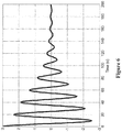
Figure 6 shows the effect of enabling the low amplification algorithm variant M2, for the same ship parameters as in Example 1. The selected algorithm is by decreasing the amplification from: 80 to 75. It can be seen that rolling is still present, but damped in about 9 cycles. - Example 3.
Figure 7 shows the effect of enabling the variant of the method CS by the algorithm M1, for the same ship parameters as in Example 1. The time delay of the speed controller is increased from 1 second to 50 seconds and the amplification is again 80 corresponding to the critical rolling. It can be seen that the effect is stronger damping compared to the case in Example 2, the rolling being damped in about 7 cycles. The speed control will be more affected as compared to the case in Example 2 since the speed control will not act for 50 seconds. - Example 4.
Figure 8 shows the effect of enabling the variant of the constant speed method CS by the algorithm M3, for the same ship parameters as in Example 1. The time delay of the speed controller is again 1 seconds but the amplification is now -50, i.e. inverted control. It can be seen that the effect is a stronger damping compared to the case in Example 3, the rolling being averted in about 4 cycles at the price of a possible larger speed control error for a time interval of 80 seconds. - Example 5.
Figure 9 shows a critical rolling of type parametric rolling obtained from equation (E1) when waves are characterised by Kw=56 and Tw=Ts/2=10 seconds. The speed controller parameters are the same as in Example 1. - Example 6.
Figure 10 shows a damping effect for the parametric rolling shown in Example 5. The algorithm is inverse control (IC), using an amplification factor of -30. The damping is not that strong, however, parametric rolling is dangerous for ship safety and there are no effective damping methods available. Thus any obtained damping is valuable.
Claims (7)
- A method for averting and damping rolling of a marine ship with propeller propulsion, wherein the current heel angle (θ) of the ship is sensed,
characterized by that- a sequence of said sensed heel angles (θ) is used to compute values that characterize the behavior of the ship's rolling comprising rolling amplitude, rolling period and trends of the rolling amplitude and rolling period,- a model is used to characterize the behavior of the ship's rolling as a critical interaction between the ship's dynamics and an engine/propeller speed controller (304) of the ship, due to which critical interaction part of a propulsion energy of the ship is converted to rolling, so that the said critical interaction increases or maintains the rolling of the ship,- signals that are related to the ship's rolling, including their derivatives of first and second order, and parameters that effect the ship's rolling, characterize together the ship's dynamics and are used in the said model,- a selection of a proper control algorithm is done, based on the said model and on the said computed values that characterize the behavior of the ship's rolling, to avert and damp the said critical interaction between the ship's dynamics and the engine/propeller speed controller (304) by modifying the function of the engine/propeller speed controller (304) such that the said critical interaction is counteracted. - Method according to claim 1, wherein averting and damping of the said critical interaction is done by predicting the forthcoming variations of the heel angle (θ) using wave encounter values, wind angles and ship heading angles obtained from either previous measurements or from generally available marine information sources such as weather reports, wave and wind reports and satellite positioning systems.
- Method according to any one of claims 1-2, wherein the said control algorithm increases the response time of the engine/propeller speed controller (304), hence propeller speed changes occur slower than the ship's rolling period and thus the ship's heel angle (θ) is not affected by engine load variations, averting in this way the said critical interaction.
- Method according to any one of claims 1-2, wherein the said control algorithm reduces the amplification of the engine/propeller speed controller (304) or alternatively is inverting the sign of this amplification, in effect reducing or countering engine load variations of the ship caused by rolling, decreasing or damping in this way the said critical interaction.
- Method according to any one of the preceding claims, wherein speed variations of the ship are compensated by interleaving engine/speed control with the said control algorithm.
- A computer program comprising computer program codes for carrying out the steps of a method according to any one of the claims 1-5.
- A computer readable medium comprising a computer program according to claim 6.
Applications Claiming Priority (2)
| Application Number | Priority Date | Filing Date | Title |
|---|---|---|---|
| SE1130084A SE1130084A1 (en) | 2011-09-16 | 2011-09-16 | Method and apparatus for avoiding and attenuating the rolling of a ship |
| PCT/SE2012/050955 WO2013039445A1 (en) | 2011-09-16 | 2012-09-11 | Method and device for averting and damping rolling of a ship |
Publications (3)
| Publication Number | Publication Date |
|---|---|
| EP2748060A1 EP2748060A1 (en) | 2014-07-02 |
| EP2748060A4 EP2748060A4 (en) | 2016-03-02 |
| EP2748060B1 true EP2748060B1 (en) | 2018-04-25 |
Family
ID=47790726
Family Applications (1)
| Application Number | Title | Priority Date | Filing Date |
|---|---|---|---|
| EP12831107.3A Not-in-force EP2748060B1 (en) | 2011-09-16 | 2012-09-11 | Method and device for averting and damping rolling of a ship |
Country Status (8)
| Country | Link |
|---|---|
| US (1) | US9145191B2 (en) |
| EP (1) | EP2748060B1 (en) |
| JP (1) | JP6195122B2 (en) |
| KR (1) | KR101980367B1 (en) |
| CN (1) | CN103813958B (en) |
| DK (1) | DK2748060T3 (en) |
| SE (1) | SE1130084A1 (en) |
| WO (1) | WO2013039445A1 (en) |
Families Citing this family (16)
| Publication number | Priority date | Publication date | Assignee | Title |
|---|---|---|---|---|
| EP3071475B1 (en) | 2013-11-18 | 2019-04-03 | AB Volvo Penta | A method for controlling a boat comprising a pivotable drive unit, and a electronic vessel control unit for steering a boat |
| CN105022861B (en) * | 2015-06-11 | 2018-05-22 | 北京精密机电控制设备研究所 | A kind of carrier rocket definite method of squash type servo-drive system oil storage |
| CN105468046B (en) * | 2016-01-08 | 2017-08-11 | 中国船舶重工集团公司第七0四研究所 | The many branched power local vibration control methods of ship basic propulsion system |
| EP3494039B1 (en) * | 2016-08-05 | 2021-04-14 | ZF Friedrichshafen AG | Sailboat steering system and method for steering a sailboat |
| CN107140110B (en) * | 2017-03-21 | 2019-07-09 | 山东省科学院海洋仪器仪表研究所 | A nonlinear damping coefficient identification method for large ship rolling motion |
| WO2018228696A1 (en) * | 2017-06-15 | 2018-12-20 | Abb Schweiz Ag | Controlling marine vessel |
| CN109358495B (en) * | 2018-12-05 | 2024-01-30 | 山东智翼航空科技有限公司 | Unmanned ship pitch-rotating speed differential stabilization and stabilization system and method |
| NO345528B1 (en) | 2018-12-20 | 2021-03-29 | Kongsberg Maritime CM AS | Vessel environment condition assessment system and method |
| CN109850082B (en) * | 2019-04-12 | 2020-04-10 | 北京虹湾威鹏信息技术有限公司 | Unmanned ship self-righting method |
| WO2022097143A1 (en) * | 2020-11-05 | 2022-05-12 | Marine Edge Ltd | Compensating for ambient torsional loads affecting marine vessel propulsion |
| US11175663B1 (en) * | 2021-03-15 | 2021-11-16 | Sea Machines Robotics, Inc. | Automated marine navigation |
| CN113212681B (en) * | 2021-04-28 | 2023-06-09 | 江苏信息职业技术学院 | Ship rolling period monitoring method |
| CN114167883B (en) * | 2022-02-11 | 2022-04-15 | 中国空气动力研究与发展中心计算空气动力研究所 | Method for controlling attitude of high-altitude aircraft by jet flow |
| WO2024098334A1 (en) * | 2022-11-10 | 2024-05-16 | 广东逸动科技有限公司 | Thruster, water area movable device and stabilization control method therefor, and storage medium |
| CN116540699B (en) * | 2023-04-14 | 2024-09-24 | 大连海事大学 | Ship navigation control method based on model predictive control under severe sea conditions |
| ES3039358A1 (en) * | 2024-04-19 | 2025-10-20 | Univ Del Pais Vasco / Euskal Herriko Unibertsitatea | METHOD AND SYSTEM FOR CONTROLLING THE INCLINATION OF AN OSCILLATING STRUCTURE |
Family Cites Families (15)
| Publication number | Priority date | Publication date | Assignee | Title |
|---|---|---|---|---|
| US1821242A (en) * | 1928-08-18 | 1931-09-01 | Old Colony Trust Company | Gaseous conduction apparatus |
| US1774825A (en) * | 1928-09-04 | 1930-09-02 | Dow Chemical Co | Method of stabilizing ships |
| FR2053697A5 (en) * | 1969-07-15 | 1971-04-16 | Polouektoff Jean Paul | |
| JPS6067300U (en) * | 1983-10-17 | 1985-05-13 | 三菱重工業株式会社 | Anti-rolling ship using main engine |
| NL8902595A (en) * | 1989-10-19 | 1991-05-16 | Rietschoten & Houwens Elek | DEVICE FOR STABILIZING A VESSEL. |
| DE19537989A1 (en) * | 1995-10-12 | 1997-04-17 | En Umwelt Beratung E V I | Determining and quantifying dynamic sea state influence on power variations of ship drive system |
| JP2004009785A (en) * | 2002-06-04 | 2004-01-15 | Mitsubishi Heavy Ind Ltd | Wave prediction fluctuating reduction method and its apparatus |
| NL1023921C2 (en) * | 2003-07-15 | 2005-01-18 | Quantum Controls B V | Active pendulum damping system for ship movements. |
| DE10355052B4 (en) * | 2003-07-19 | 2006-11-02 | Dallach, Gert, Dr. Ing. | Stability determination of ships |
| NO320465B1 (en) * | 2004-02-16 | 2005-12-12 | Egeland Olav | Procedure and system for testing a regulatory system of a marine vessel |
| JP4262127B2 (en) * | 2004-03-30 | 2009-05-13 | Jfeソルデック株式会社 | Parametric roll prevention device |
| US20080183341A1 (en) * | 2006-08-22 | 2008-07-31 | Neu Wayne L | Method and apparatus for torque control for machinery using counter-rotating drives |
| CN100568141C (en) * | 2008-03-20 | 2009-12-09 | 北京航空航天大学 | A control method for unmanned aerial vehicle roll leveling |
| DK2419804T3 (en) * | 2009-04-14 | 2014-02-24 | Univ Danmarks Tekniske | Prediction of resonant swing |
| NO20093007A1 (en) * | 2009-09-16 | 2011-03-17 | Kongsberg Seatex As | Fartoybevegelser |
-
2011
- 2011-09-16 SE SE1130084A patent/SE1130084A1/en not_active IP Right Cessation
-
2012
- 2012-09-11 EP EP12831107.3A patent/EP2748060B1/en not_active Not-in-force
- 2012-09-11 CN CN201280045080.1A patent/CN103813958B/en not_active Expired - Fee Related
- 2012-09-11 KR KR1020147010183A patent/KR101980367B1/en not_active Expired - Fee Related
- 2012-09-11 US US14/211,547 patent/US9145191B2/en active Active
- 2012-09-11 WO PCT/SE2012/050955 patent/WO2013039445A1/en not_active Ceased
- 2012-09-11 JP JP2014530628A patent/JP6195122B2/en not_active Expired - Fee Related
- 2012-09-11 DK DK12831107.3T patent/DK2748060T3/en active
Non-Patent Citations (1)
| Title |
|---|
| None * |
Also Published As
| Publication number | Publication date |
|---|---|
| SE535979C2 (en) | 2013-03-12 |
| CN103813958A (en) | 2014-05-21 |
| CN103813958B (en) | 2017-10-03 |
| KR101980367B1 (en) | 2019-05-20 |
| KR20140061547A (en) | 2014-05-21 |
| JP2014531360A (en) | 2014-11-27 |
| US20140316620A1 (en) | 2014-10-23 |
| US9145191B2 (en) | 2015-09-29 |
| EP2748060A4 (en) | 2016-03-02 |
| JP6195122B2 (en) | 2017-09-13 |
| SE1130084A1 (en) | 2013-03-12 |
| EP2748060A1 (en) | 2014-07-02 |
| DK2748060T3 (en) | 2018-07-23 |
| WO2013039445A1 (en) | 2013-03-21 |
Similar Documents
| Publication | Publication Date | Title |
|---|---|---|
| US9145191B2 (en) | Method and device for averting and damping rolling of a ship | |
| Marzouk et al. | Control of ship roll using passive and active anti-roll tanks | |
| Yasukawa et al. | Application of the MMG method for the prediction of steady sailing condition and course stability of a ship under external disturbances | |
| Tannuri et al. | Dynamic positioning systems: An experimental analysis of sliding mode control | |
| Townsend et al. | Control strategies for marine gyrostabilizers | |
| JP4640760B2 (en) | Waveform prediction method of incoming waves and driving control method of navigation body in waves | |
| CN109739248B (en) | The stability control method of shipborne three-degree-of-freedom parallel stable platform based on ADRC | |
| EP2332821A1 (en) | Method of controlling the position of moored marine vessels | |
| Chuang et al. | Speed loss of a vessel sailing in oblique waves | |
| Kula | An overview of roll stabilizers and systems for their control | |
| Fitriadhy et al. | Course stability of a ship towing system | |
| Aung et al. | Manoeuvring simulations in adverse weather conditions with the effects of propeller and rudder emergence taken into account | |
| Ueno et al. | Rudder effectiveness correction for scale model ship testing | |
| Kerdraon et al. | Development of a 6-DOF Dynamic Velocity Prediction Program for offshore racing yachts | |
| Cakici et al. | Numerical roll motion control by using fins based on the linear quadratic regulator and dynamic mode decomposition | |
| Awad et al. | Ship roll damping via direct inverse neural network control system | |
| Khaled et al. | A dynamic model and a robust controller for a fully-actuated marine surface vessel | |
| Söder et al. | Parametric roll mitigation using rudder control | |
| Tsopelakos et al. | Design and evaluation of dynamic positioning controllers with parasitic thrust reduction for an overactuated floating platform | |
| Hashimoto et al. | Broaching prediction of a wave-piercing tumblehome vessel with twin screws and twin rudders | |
| Agostinho et al. | Sliding mode control applied to offshore dynamic positioning systems | |
| Patil et al. | A time-domain method for analyzing the ship roll stabilization based on active fin control | |
| Li et al. | Handling roll constraints for path following of marine surface vessels using coordinated rudder and propulsion control | |
| Kazerooni et al. | Experimental evaluation of forward speed effect on maneuvering hydrodynamic derivatives of a planing hull | |
| Cakici et al. | Improved Ship Roll Motion Performance with Combined EKF Parameter Estimation and MPC Control |
Legal Events
| Date | Code | Title | Description |
|---|---|---|---|
| PUAI | Public reference made under article 153(3) epc to a published international application that has entered the european phase |
Free format text: ORIGINAL CODE: 0009012 |
|
| 17P | Request for examination filed |
Effective date: 20140221 |
|
| AK | Designated contracting states |
Kind code of ref document: A1 Designated state(s): AL AT BE BG CH CY CZ DE DK EE ES FI FR GB GR HR HU IE IS IT LI LT LU LV MC MK MT NL NO PL PT RO RS SE SI SK SM TR |
|
| DAX | Request for extension of the european patent (deleted) | ||
| RA4 | Supplementary search report drawn up and despatched (corrected) |
Effective date: 20160201 |
|
| RIC1 | Information provided on ipc code assigned before grant |
Ipc: B63B 39/08 20060101ALI20160126BHEP Ipc: G05D 1/08 20060101ALI20160126BHEP Ipc: B63B 39/00 20060101AFI20160126BHEP |
|
| GRAP | Despatch of communication of intention to grant a patent |
Free format text: ORIGINAL CODE: EPIDOSNIGR1 |
|
| INTG | Intention to grant announced |
Effective date: 20171023 |
|
| RIN1 | Information on inventor provided before grant (corrected) |
Inventor name: LOEFGREN, ARNE Inventor name: FODOR, GEORGE Inventor name: LINDQVIST, TOMAS |
|
| GRAS | Grant fee paid |
Free format text: ORIGINAL CODE: EPIDOSNIGR3 |
|
| GRAA | (expected) grant |
Free format text: ORIGINAL CODE: 0009210 |
|
| AK | Designated contracting states |
Kind code of ref document: B1 Designated state(s): AL AT BE BG CH CY CZ DE DK EE ES FI FR GB GR HR HU IE IS IT LI LT LU LV MC MK MT NL NO PL PT RO RS SE SI SK SM TR |
|
| RAP1 | Party data changed (applicant data changed or rights of an application transferred) |
Owner name: Q-TAGG R&D AB |
|
| REG | Reference to a national code |
Ref country code: GB Ref legal event code: FG4D |
|
| REG | Reference to a national code |
Ref country code: CH Ref legal event code: EP |
|
| REG | Reference to a national code |
Ref country code: AT Ref legal event code: REF Ref document number: 992579 Country of ref document: AT Kind code of ref document: T Effective date: 20180515 |
|
| REG | Reference to a national code |
Ref country code: IE Ref legal event code: FG4D |
|
| REG | Reference to a national code |
Ref country code: DE Ref legal event code: R096 Ref document number: 602012045731 Country of ref document: DE |
|
| REG | Reference to a national code |
Ref country code: DK Ref legal event code: T3 Effective date: 20180716 |
|
| REG | Reference to a national code |
Ref country code: NL Ref legal event code: FP |
|
| REG | Reference to a national code |
Ref country code: NO Ref legal event code: T2 Effective date: 20180425 |
|
| REG | Reference to a national code |
Ref country code: LT Ref legal event code: MG4D |
|
| PG25 | Lapsed in a contracting state [announced via postgrant information from national office to epo] |
Ref country code: BG Free format text: LAPSE BECAUSE OF FAILURE TO SUBMIT A TRANSLATION OF THE DESCRIPTION OR TO PAY THE FEE WITHIN THE PRESCRIBED TIME-LIMIT Effective date: 20180725 Ref country code: PL Free format text: LAPSE BECAUSE OF FAILURE TO SUBMIT A TRANSLATION OF THE DESCRIPTION OR TO PAY THE FEE WITHIN THE PRESCRIBED TIME-LIMIT Effective date: 20180425 Ref country code: SE Free format text: LAPSE BECAUSE OF FAILURE TO SUBMIT A TRANSLATION OF THE DESCRIPTION OR TO PAY THE FEE WITHIN THE PRESCRIBED TIME-LIMIT Effective date: 20180425 Ref country code: ES Free format text: LAPSE BECAUSE OF FAILURE TO SUBMIT A TRANSLATION OF THE DESCRIPTION OR TO PAY THE FEE WITHIN THE PRESCRIBED TIME-LIMIT Effective date: 20180425 Ref country code: LT Free format text: LAPSE BECAUSE OF FAILURE TO SUBMIT A TRANSLATION OF THE DESCRIPTION OR TO PAY THE FEE WITHIN THE PRESCRIBED TIME-LIMIT Effective date: 20180425 |
|
| PG25 | Lapsed in a contracting state [announced via postgrant information from national office to epo] |
Ref country code: LV Free format text: LAPSE BECAUSE OF FAILURE TO SUBMIT A TRANSLATION OF THE DESCRIPTION OR TO PAY THE FEE WITHIN THE PRESCRIBED TIME-LIMIT Effective date: 20180425 Ref country code: HR Free format text: LAPSE BECAUSE OF FAILURE TO SUBMIT A TRANSLATION OF THE DESCRIPTION OR TO PAY THE FEE WITHIN THE PRESCRIBED TIME-LIMIT Effective date: 20180425 Ref country code: GR Free format text: LAPSE BECAUSE OF FAILURE TO SUBMIT A TRANSLATION OF THE DESCRIPTION OR TO PAY THE FEE WITHIN THE PRESCRIBED TIME-LIMIT Effective date: 20180726 Ref country code: RS Free format text: LAPSE BECAUSE OF FAILURE TO SUBMIT A TRANSLATION OF THE DESCRIPTION OR TO PAY THE FEE WITHIN THE PRESCRIBED TIME-LIMIT Effective date: 20180425 |
|
| REG | Reference to a national code |
Ref country code: AT Ref legal event code: MK05 Ref document number: 992579 Country of ref document: AT Kind code of ref document: T Effective date: 20180425 |
|
| PG25 | Lapsed in a contracting state [announced via postgrant information from national office to epo] |
Ref country code: PT Free format text: LAPSE BECAUSE OF FAILURE TO SUBMIT A TRANSLATION OF THE DESCRIPTION OR TO PAY THE FEE WITHIN THE PRESCRIBED TIME-LIMIT Effective date: 20180827 |
|
| REG | Reference to a national code |
Ref country code: DE Ref legal event code: R097 Ref document number: 602012045731 Country of ref document: DE |
|
| PG25 | Lapsed in a contracting state [announced via postgrant information from national office to epo] |
Ref country code: EE Free format text: LAPSE BECAUSE OF FAILURE TO SUBMIT A TRANSLATION OF THE DESCRIPTION OR TO PAY THE FEE WITHIN THE PRESCRIBED TIME-LIMIT Effective date: 20180425 Ref country code: RO Free format text: LAPSE BECAUSE OF FAILURE TO SUBMIT A TRANSLATION OF THE DESCRIPTION OR TO PAY THE FEE WITHIN THE PRESCRIBED TIME-LIMIT Effective date: 20180425 Ref country code: AT Free format text: LAPSE BECAUSE OF FAILURE TO SUBMIT A TRANSLATION OF THE DESCRIPTION OR TO PAY THE FEE WITHIN THE PRESCRIBED TIME-LIMIT Effective date: 20180425 Ref country code: CZ Free format text: LAPSE BECAUSE OF FAILURE TO SUBMIT A TRANSLATION OF THE DESCRIPTION OR TO PAY THE FEE WITHIN THE PRESCRIBED TIME-LIMIT Effective date: 20180425 Ref country code: SK Free format text: LAPSE BECAUSE OF FAILURE TO SUBMIT A TRANSLATION OF THE DESCRIPTION OR TO PAY THE FEE WITHIN THE PRESCRIBED TIME-LIMIT Effective date: 20180425 |
|
| PG25 | Lapsed in a contracting state [announced via postgrant information from national office to epo] |
Ref country code: SM Free format text: LAPSE BECAUSE OF FAILURE TO SUBMIT A TRANSLATION OF THE DESCRIPTION OR TO PAY THE FEE WITHIN THE PRESCRIBED TIME-LIMIT Effective date: 20180425 Ref country code: IT Free format text: LAPSE BECAUSE OF FAILURE TO SUBMIT A TRANSLATION OF THE DESCRIPTION OR TO PAY THE FEE WITHIN THE PRESCRIBED TIME-LIMIT Effective date: 20180425 |
|
| PLBE | No opposition filed within time limit |
Free format text: ORIGINAL CODE: 0009261 |
|
| STAA | Information on the status of an ep patent application or granted ep patent |
Free format text: STATUS: NO OPPOSITION FILED WITHIN TIME LIMIT |
|
| 26N | No opposition filed |
Effective date: 20190128 |
|
| PG25 | Lapsed in a contracting state [announced via postgrant information from national office to epo] |
Ref country code: MC Free format text: LAPSE BECAUSE OF FAILURE TO SUBMIT A TRANSLATION OF THE DESCRIPTION OR TO PAY THE FEE WITHIN THE PRESCRIBED TIME-LIMIT Effective date: 20180425 |
|
| REG | Reference to a national code |
Ref country code: CH Ref legal event code: PL |
|
| PG25 | Lapsed in a contracting state [announced via postgrant information from national office to epo] |
Ref country code: SI Free format text: LAPSE BECAUSE OF FAILURE TO SUBMIT A TRANSLATION OF THE DESCRIPTION OR TO PAY THE FEE WITHIN THE PRESCRIBED TIME-LIMIT Effective date: 20180425 |
|
| REG | Reference to a national code |
Ref country code: BE Ref legal event code: MM Effective date: 20180930 |
|
| REG | Reference to a national code |
Ref country code: IE Ref legal event code: MM4A |
|
| PG25 | Lapsed in a contracting state [announced via postgrant information from national office to epo] |
Ref country code: LU Free format text: LAPSE BECAUSE OF NON-PAYMENT OF DUE FEES Effective date: 20180911 |
|
| PG25 | Lapsed in a contracting state [announced via postgrant information from national office to epo] |
Ref country code: IE Free format text: LAPSE BECAUSE OF NON-PAYMENT OF DUE FEES Effective date: 20180911 |
|
| PG25 | Lapsed in a contracting state [announced via postgrant information from national office to epo] |
Ref country code: CH Free format text: LAPSE BECAUSE OF NON-PAYMENT OF DUE FEES Effective date: 20180930 Ref country code: BE Free format text: LAPSE BECAUSE OF NON-PAYMENT OF DUE FEES Effective date: 20180930 Ref country code: LI Free format text: LAPSE BECAUSE OF NON-PAYMENT OF DUE FEES Effective date: 20180930 Ref country code: FR Free format text: LAPSE BECAUSE OF NON-PAYMENT OF DUE FEES Effective date: 20180930 |
|
| PG25 | Lapsed in a contracting state [announced via postgrant information from national office to epo] |
Ref country code: AL Free format text: LAPSE BECAUSE OF FAILURE TO SUBMIT A TRANSLATION OF THE DESCRIPTION OR TO PAY THE FEE WITHIN THE PRESCRIBED TIME-LIMIT Effective date: 20180425 |
|
| PG25 | Lapsed in a contracting state [announced via postgrant information from national office to epo] |
Ref country code: MT Free format text: LAPSE BECAUSE OF NON-PAYMENT OF DUE FEES Effective date: 20180911 |
|
| PG25 | Lapsed in a contracting state [announced via postgrant information from national office to epo] |
Ref country code: TR Free format text: LAPSE BECAUSE OF FAILURE TO SUBMIT A TRANSLATION OF THE DESCRIPTION OR TO PAY THE FEE WITHIN THE PRESCRIBED TIME-LIMIT Effective date: 20180425 |
|
| PG25 | Lapsed in a contracting state [announced via postgrant information from national office to epo] |
Ref country code: HU Free format text: LAPSE BECAUSE OF FAILURE TO SUBMIT A TRANSLATION OF THE DESCRIPTION OR TO PAY THE FEE WITHIN THE PRESCRIBED TIME-LIMIT; INVALID AB INITIO Effective date: 20120911 |
|
| PG25 | Lapsed in a contracting state [announced via postgrant information from national office to epo] |
Ref country code: CY Free format text: LAPSE BECAUSE OF FAILURE TO SUBMIT A TRANSLATION OF THE DESCRIPTION OR TO PAY THE FEE WITHIN THE PRESCRIBED TIME-LIMIT Effective date: 20180425 Ref country code: MK Free format text: LAPSE BECAUSE OF NON-PAYMENT OF DUE FEES Effective date: 20180425 |
|
| PG25 | Lapsed in a contracting state [announced via postgrant information from national office to epo] |
Ref country code: IS Free format text: LAPSE BECAUSE OF FAILURE TO SUBMIT A TRANSLATION OF THE DESCRIPTION OR TO PAY THE FEE WITHIN THE PRESCRIBED TIME-LIMIT Effective date: 20180825 |
|
| REG | Reference to a national code |
Ref country code: DE Ref legal event code: R082 Ref document number: 602012045731 Country of ref document: DE Representative=s name: BECKER KURIG & PARTNER PATENTANWAELTE MBB, DE Ref country code: DE Ref legal event code: R082 Ref document number: 602012045731 Country of ref document: DE Representative=s name: BECKER & KURIG PARTNERSCHAFT PATENTANWAELTE MB, DE |
|
| REG | Reference to a national code |
Ref country code: DE Ref legal event code: R084 Ref document number: 602012045731 Country of ref document: DE |
|
| PGFP | Annual fee paid to national office [announced via postgrant information from national office to epo] |
Ref country code: NO Payment date: 20220913 Year of fee payment: 11 Ref country code: NL Payment date: 20220913 Year of fee payment: 11 Ref country code: GB Payment date: 20220912 Year of fee payment: 11 Ref country code: FI Payment date: 20220913 Year of fee payment: 11 Ref country code: DK Payment date: 20220914 Year of fee payment: 11 Ref country code: DE Payment date: 20220913 Year of fee payment: 11 |
|
| REG | Reference to a national code |
Ref country code: DE Ref legal event code: R119 Ref document number: 602012045731 Country of ref document: DE |
|
| REG | Reference to a national code |
Ref country code: DK Ref legal event code: EBP Effective date: 20230930 |
|
| PG25 | Lapsed in a contracting state [announced via postgrant information from national office to epo] |
Ref country code: FI Free format text: LAPSE BECAUSE OF NON-PAYMENT OF DUE FEES Effective date: 20230911 |
|
| REG | Reference to a national code |
Ref country code: NL Ref legal event code: MM Effective date: 20231001 |
|
| GBPC | Gb: european patent ceased through non-payment of renewal fee |
Effective date: 20230911 |
|
| PG25 | Lapsed in a contracting state [announced via postgrant information from national office to epo] |
Ref country code: NL Free format text: LAPSE BECAUSE OF NON-PAYMENT OF DUE FEES Effective date: 20231001 |
|
| PG25 | Lapsed in a contracting state [announced via postgrant information from national office to epo] |
Ref country code: NL Free format text: LAPSE BECAUSE OF NON-PAYMENT OF DUE FEES Effective date: 20231001 |
|
| PG25 | Lapsed in a contracting state [announced via postgrant information from national office to epo] |
Ref country code: GB Free format text: LAPSE BECAUSE OF NON-PAYMENT OF DUE FEES Effective date: 20230911 |
|
| PG25 | Lapsed in a contracting state [announced via postgrant information from national office to epo] |
Ref country code: NO Free format text: LAPSE BECAUSE OF NON-PAYMENT OF DUE FEES Effective date: 20230930 Ref country code: GB Free format text: LAPSE BECAUSE OF NON-PAYMENT OF DUE FEES Effective date: 20230911 Ref country code: DE Free format text: LAPSE BECAUSE OF NON-PAYMENT OF DUE FEES Effective date: 20240403 |
|
| PG25 | Lapsed in a contracting state [announced via postgrant information from national office to epo] |
Ref country code: DK Free format text: LAPSE BECAUSE OF NON-PAYMENT OF DUE FEES Effective date: 20230930 |
|
| PG25 | Lapsed in a contracting state [announced via postgrant information from national office to epo] |
Ref country code: DK Free format text: LAPSE BECAUSE OF NON-PAYMENT OF DUE FEES Effective date: 20230930 |