EP2747965B2 - Battery powered rear handle chain saw - Google Patents
Battery powered rear handle chain saw Download PDFInfo
- Publication number
- EP2747965B2 EP2747965B2 EP11871730.5A EP11871730A EP2747965B2 EP 2747965 B2 EP2747965 B2 EP 2747965B2 EP 11871730 A EP11871730 A EP 11871730A EP 2747965 B2 EP2747965 B2 EP 2747965B2
- Authority
- EP
- European Patent Office
- Prior art keywords
- chain saw
- rotation axis
- longitudinal
- handle
- battery
- Prior art date
- Legal status (The legal status is an assumption and is not a legal conclusion. Google has not performed a legal analysis and makes no representation as to the accuracy of the status listed.)
- Active
Links
Images

Classifications
-
- B—PERFORMING OPERATIONS; TRANSPORTING
- B27—WORKING OR PRESERVING WOOD OR SIMILAR MATERIAL; NAILING OR STAPLING MACHINES IN GENERAL
- B27B—SAWS FOR WOOD OR SIMILAR MATERIAL; COMPONENTS OR ACCESSORIES THEREFOR
- B27B17/00—Chain saws; Equipment therefor
- B27B17/0008—Means for carrying the chain saw, e.g. handles
-
- B—PERFORMING OPERATIONS; TRANSPORTING
- B25—HAND TOOLS; PORTABLE POWER-DRIVEN TOOLS; MANIPULATORS
- B25F—COMBINATION OR MULTI-PURPOSE TOOLS NOT OTHERWISE PROVIDED FOR; DETAILS OR COMPONENTS OF PORTABLE POWER-DRIVEN TOOLS NOT PARTICULARLY RELATED TO THE OPERATIONS PERFORMED AND NOT OTHERWISE PROVIDED FOR
- B25F5/00—Details or components of portable power-driven tools not particularly related to the operations performed and not otherwise provided for
- B25F5/02—Construction of casings, bodies or handles
-
- B—PERFORMING OPERATIONS; TRANSPORTING
- B27—WORKING OR PRESERVING WOOD OR SIMILAR MATERIAL; NAILING OR STAPLING MACHINES IN GENERAL
- B27B—SAWS FOR WOOD OR SIMILAR MATERIAL; COMPONENTS OR ACCESSORIES THEREFOR
- B27B17/00—Chain saws; Equipment therefor
- B27B17/02—Chain saws equipped with guide bar
Definitions
- This invention relates to battery-powered chain saws. Especially, the invention deals with a battery-powered chain saw according to the preamble of claim 1 and having a rear handle and a front handle.
- Such a chain saw is known from US2010/0218386 A1 or EP2438808A1 , which is a document according to Article 54(3) EPC.
- Battery-powered chain saws are well known in the art.
- One example is shown in the European Patent application EP 1 787 507 which discloses a power tool comprising a main body housing a motor, a working implement in drivable engagement with the motor, and a handle assembly associated with the main body.
- the handle assembly has a main handle positioned on that side of the main body remote from the working implement, a first auxiliary handle positioned on that side of the main body facing the working implement, and a second auxiliary handle positioned on that side of the main handle remote from the working implement.
- a battery-powered chain saw defined by the features of claim 1. Further preferred embodiments are defined by the features of dependent claims 2-4.
- the chain saw according to the invention as defined by claim 1, a favorable distribution of masses may be achieved within the chain saw even a rater heavy battery pack is used. Since the high capacity batteries required for professional use of the saw tend to be heavy, such a configuration is particularly favorable in chain saws where high capacity batteries are needed. As a result, battery-powered chain saws for demanding users may be manufactured, which chain saws are comfortable to carry and maneuver.
- the vertical plane comprising the longitudinal rotation axis also comprises a longitudinal center line of the rear handle.
- the vertical plane comprising the longitudinal rotation axis of the chain saw is essentially parallel with a main extension plane of a cutting element supporting guide bar extending from the front end of the housing.
- the upper portion of the front handle extends in an essentially transversal direction of the chain saw.
- the motor rotation axis extends in a direction which is essentially parallel with the transversal direction of the chain saw.
- the vertical direction is a direction perpendicular to a support surface on which the saw body may be positioned, i.e. the Y direction in the drawings.
- the support surface extends in a lateral plane which is shown as the XZ-plane in the drawings.
- the terms upwards and downwards are based on a normal working position of the saw.
- the front end of the saw is the end distal to an operator during normal use of the saw.
- the rear end is the end proximal to the operator during normal use.
- the longitudinal direction is shown as the X direction in the drawings, whereas the transversal direction is shown as the Z direction in the drawings.
- left and right are defined based on an operator holding the saw in an operating position.
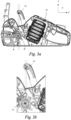
- the saw has a main handle 20 in the form of a rear handle 20 and a support handle 30 in the form of a front handle 30.
- the saw 1 has a body portion 10 to which the handles 20, 30 and a chain guiding bar 50 are connected.
- the guide bar 50 is partially shown in Fig. 2 , whereas it is omitted in Figs. 1 and 3a-3b .
- the front end of the guide bar 50 is omitted in Fig. 2 .
- the guide bar extends from a front end 12 of the body portion 10, in a longitudinal direction of the saw.
- the body portion 10 extends between a front end 12 and a rear end 11.
- the guide bar is arranged to support a saw chain, which is not shown in the figures.
- the rear handle 20 extends in the longitudinal direction X of the saw.
- the front handle has an essentially U-shaped configuration, with an upper portion 31, interconnecting a left leg portion 32 and a right leg portion 33, as seen from an operator's point of view.
- the leg portions are connected to the body portion 10 in their lower ends 32a, 33a.
- the upper portion 31 of the front handle 30 shown in the figures is configured such that an imaginary center axis A2 of the portion 31 extends in a direction which is parallel with the XZ plane.
- the center axis may be slightly angled relative to the XZ-plane.
- the center axis A2 of the upper portion 31 is angled relative to the Z direction shown in the figures, i.e. relative to the transversal direction.
- the center axis of the upper portion may extend in the transversal direction Z.
- the body portion comprises a battery pack 80 which is arranged to supply electric power to an electric motor 40.
- the electric motor is also arranged in the body portion.
- the motor has a rotation axis A1.
- the motor rotation axis may extend in the Z direction, as in the embodiment shown in figures.
- the motor axis A1 may also extend in other directions.
- the saw 1 has a longitudinal rotation axis X1, extending in the longitudinal direction X.
- the vertical plane P comprising the longitudinal rotation axis X1 also comprises a longitudinal center line of the rear handle.
- the vertical plane P is the plane of the paper.
- the longitudinal center line is parallel with the extension direction of the guide bar.
- the guide bar may be displaced in the Z direction relative to the longitudinal center axis of the saw, such that the plane defined by the guide bar is parallel to but not coincident with the vertical plan P comprising the longitudinal rotation axis.
- a favorable distribution of masses within the chainsaw may be achieved if the front handle 30 and the motor rotation axis A1 are arranged so that the point 60 is located rearwardly of the point 70 as seen from above in Fig. 3b .
- the location of point 60 is defined by an X-coordinate that is greater than an X-coordinate of the location of point 70.
- the X-direction is pointing in a rearward direction of the chainsaw and is generally parallel with a flat ground surface as the chainsaw is put away in an inoperable rest position.
Landscapes
- Life Sciences & Earth Sciences (AREA)
- Engineering & Computer Science (AREA)
- Mechanical Engineering (AREA)
- Wood Science & Technology (AREA)
- Forests & Forestry (AREA)
- Sawing (AREA)
Description
- This invention relates to battery-powered chain saws. Especially, the invention deals with a battery-powered chain saw according to the preamble of claim 1 and having a rear handle and a front handle.
- Such a chain saw is known from
US2010/0218386 A1 orEP2438808A1 , which is a document according to Article 54(3) EPC. - Battery-powered chain saws are well known in the art. One example is shown in the European Patent application
EP 1 787 507 which discloses a power tool comprising a main body housing a motor, a working implement in drivable engagement with the motor, and a handle assembly associated with the main body. The handle assembly has a main handle positioned on that side of the main body remote from the working implement, a first auxiliary handle positioned on that side of the main body facing the working implement, and a second auxiliary handle positioned on that side of the main handle remote from the working implement. - However, there remains a need for battery-powered chain saws targeted for demanding consumers and professional users, having high expectations regarding the performance as well as the maneuverability of the saws.
- In order to satisfy these high expectations saws provided with powerful high energy batteries that last long and have a quick recharging possibility are required. At the same time, the saws should be comfortable to carry and maneuver, such that they can be used for long and uninterrupted work.
- Hence, there is a need for a battery-powered chain saw which provides a possibility to combine high performance and satisfactory ergonomic features.
- It is an object of the present invention to provide a battery powered chain saw which is comfortable to carry and operate and which may comprise high capacity components.
- According to the invention, there is provided a battery-powered chain saw defined by the features of claim 1. Further preferred embodiments are defined by the features of dependent claims 2-4. By configuring the chain saw according to the invention as defined by claim 1, a favorable distribution of masses may be achieved within the chain saw even a rater heavy battery pack is used. Since the high capacity batteries required for professional use of the saw tend to be heavy, such a configuration is particularly favorable in chain saws where high capacity batteries are needed. As a result, battery-powered chain saws for demanding users may be manufactured, which chain saws are comfortable to carry and maneuver.
- According to the invention, the vertical plane comprising the longitudinal rotation axis also comprises a longitudinal center line of the rear handle.
- According to the invention, the vertical plane comprising the longitudinal rotation axis of the chain saw is essentially parallel with a main extension plane of a cutting element supporting guide bar extending from the front end of the housing.
- According to the invention, the upper portion of the front handle extends in an essentially transversal direction of the chain saw.
- According to an embodiment, the motor rotation axis extends in a direction which is essentially parallel with the transversal direction of the chain saw.
- As used herein, the following terms have the following meanings:
The vertical direction is a direction perpendicular to a support surface on which the saw body may be positioned, i.e. the Y direction in the drawings. The support surface extends in a lateral plane which is shown as the XZ-plane in the drawings. - The terms upwards and downwards are based on a normal working position of the saw. The front end of the saw is the end distal to an operator during normal use of the saw. Correspondingly, the rear end is the end proximal to the operator during normal use.
- The longitudinal direction is shown as the X direction in the drawings, whereas the transversal direction is shown as the Z direction in the drawings.
- The terms left and right are defined based on an operator holding the saw in an operating position.
- The invention will be understood and appreciated more fully from the following detailed description, taken in conjunction with the drawings, in which:
-
Fig. 1 is a partial perspective view of a battery-powered rear handle chain saw according to an embodiment of the invention, -
Fig. 2 is a partial top view of a battery-powered rear handle chain saw according to an embodiment of the invention, -
Fig. 3a is a partial cross sectional view taken along line X1-X1 inFig. 2 , and -
Fig. 3b is an enlarged view of a portion of the cross section shown inFig. 3 . - The present invention will be described more fully hereinafter with reference to the accompanying drawings, in which preferred embodiments of the invention are shown. In the drawings, like numbers refer to like elements.
- Referring to
Fig. 1 , a major part of a battery-powered chain saw 1 according to embodiments herein is shown. The saw has amain handle 20 in the form of arear handle 20 and asupport handle 30 in the form of afront handle 30. - The saw 1 has a
body portion 10 to which the handles 20, 30 and a chain guiding bar 50 are connected. The guide bar 50 is partially shown inFig. 2 , whereas it is omitted inFigs. 1 and3a-3b . The front end of the guide bar 50 is omitted inFig. 2 . The guide bar extends from afront end 12 of thebody portion 10, in a longitudinal direction of the saw. - The
body portion 10 extends between afront end 12 and arear end 11. - The guide bar is arranged to support a saw chain, which is not shown in the figures.
- The
rear handle 20 extends in the longitudinal direction X of the saw. - The front handle according to the figures has an essentially U-shaped configuration, with an
upper portion 31, interconnecting aleft leg portion 32 and aright leg portion 33, as seen from an operator's point of view. The leg portions are connected to thebody portion 10 in theirlower ends - The
upper portion 31 of thefront handle 30 shown in the figures is configured such that an imaginary center axis A2 of theportion 31 extends in a direction which is parallel with the XZ plane. As an alternative, the center axis may be slightly angled relative to the XZ-plane. - In the embodiment shown in the figures, the center axis A2 of the
upper portion 31 is angled relative to the Z direction shown in the figures, i.e. relative to the transversal direction. - In alternative embodiments, the center axis of the upper portion may extend in the transversal direction Z.
- As shown in
Fig. 3a , the body portion comprises abattery pack 80 which is arranged to supply electric power to anelectric motor 40. The electric motor is also arranged in the body portion. The motor has a rotation axis A1. The motor rotation axis may extend in the Z direction, as in the embodiment shown in figures. The motor axis A1 may also extend in other directions. - The saw 1 has a longitudinal rotation axis X1, extending in the longitudinal direction X. According to the invention as shown in the figures, the vertical plane P comprising the longitudinal rotation axis X1 also comprises a longitudinal center line of the rear handle. In
Fig. 3a , the vertical plane P is the plane of the paper. - The longitudinal center line is parallel with the extension direction of the guide bar. However, the guide bar may be displaced in the Z direction relative to the longitudinal center axis of the saw, such that the plane defined by the guide bar is parallel to but not coincident with the vertical plan P comprising the longitudinal rotation axis.
- It has been noticed that a favorable distribution of masses within the chain saw may be achieved if the
front handle 30 is positioned such that apoint 60 in which the upper portion center axis A2 intersects the vertical plane P comprising the longitudinal rotation axis X1, is positioned rearwardly of apoint 70 in which the motor rotation axis A1 intersects that vertical plane P. - More specifically, a favorable distribution of masses within the chainsaw may be achieved if the
front handle 30 and the motor rotation axis A1 are arranged so that thepoint 60 is located rearwardly of thepoint 70 as seen from above inFig. 3b . Thereby the location ofpoint 60 is defined by an X-coordinate that is greater than an X-coordinate of the location ofpoint 70. As seen inFig. 3a the X-direction is pointing in a rearward direction of the chainsaw and is generally parallel with a flat ground surface as the chainsaw is put away in an inoperable rest position. - By configuring and positioning the front handle in this way, the operator will experience that the chain saw is well balanced and comfortable to use, even if a fairly heavy battery pack is used.
- In the drawings and specification, there have been disclosed preferred embodiments and examples of the invention and, although specific terms are employed, they are used in a generic and descriptive sense only and not for the purpose of limitation, the scope of the invention being set forth in the following claims.
Claims (3)
- A battery-powered chain saw, comprisinga housing (10) extending in a longitudinal direction (X) between a front end (12) and a rear end (11), the longitudinal direction (X) being parallel with a flat ground surface as the chain saw is put away in an inoperable rest position,a rear handle (20) fixedly connected to or integral with the housing (10) and extending in the longitudinal direction (X),a front handle (30) fixedly connected to the housing (10), wherein an upper portion of the front handle extends in an essentially transversal direction (Z) of the chain saw,an electric motor (40) arranged to drive a cutting element of the chain saw, the electric motor having a motor rotation axis (A1), anda cutting element supporting guide bar (50) extending from the front end (12) of the housing (10), in said longitudinal direction (X),the chain saw having a longitudinal rotation axis (X1), characterized in that a point (60) in which a center axis (A2) of an upper portion (31) of the front handle (30) intersects a vertical plane (P) comprising the longitudinal rotation axis (X1) of the chain saw and also comprising a longitudinal center line of the rear handle (20), is positioned rearwardly of a point (70) in which the motor rotation axis (A1) intersects said vertical plane (P), wherein the vertical plane (P) is essentially parallel with a main extension plane of said cutting element supporting guide bar (50).
- The battery-powered chain saw according to claim 1, wherein the vertical plane (P) comprising the longitudinal rotation axis (X1) also comprises a longitudinal center line of the rear handle (20).
- The battery powered chain saw according to any of the preceding claims, wherein the motor rotation axis (A1) extends in a direction which is essentially parallel with the transversal direction (Z) of the chain saw.
Applications Claiming Priority (1)
| Application Number | Priority Date | Filing Date | Title |
|---|---|---|---|
| PCT/SE2011/051031 WO2013032375A1 (en) | 2011-08-26 | 2011-08-26 | Battery powered rear handle chain saw |
Publications (4)
| Publication Number | Publication Date |
|---|---|
| EP2747965A1 EP2747965A1 (en) | 2014-07-02 |
| EP2747965A4 EP2747965A4 (en) | 2015-04-01 |
| EP2747965B1 EP2747965B1 (en) | 2018-05-09 |
| EP2747965B2 true EP2747965B2 (en) | 2023-09-27 |
Family
ID=47756630
Family Applications (1)
| Application Number | Title | Priority Date | Filing Date |
|---|---|---|---|
| EP11871730.5A Active EP2747965B2 (en) | 2011-08-26 | 2011-08-26 | Battery powered rear handle chain saw |
Country Status (4)
| Country | Link |
|---|---|
| US (1) | US10213936B2 (en) |
| EP (1) | EP2747965B2 (en) |
| CN (1) | CN103781604B (en) |
| WO (1) | WO2013032375A1 (en) |
Families Citing this family (18)
| Publication number | Priority date | Publication date | Assignee | Title |
|---|---|---|---|---|
| JP5146912B2 (en) * | 2008-05-23 | 2013-02-20 | 日立工機株式会社 | Chainsaw |
| DE102014004526A1 (en) * | 2014-03-27 | 2015-10-01 | Andreas Stihl Ag & Co. Kg | Hand-held implement |
| USD802387S1 (en) * | 2015-08-06 | 2017-11-14 | Andreas Stihl Ag & Co. Kg | Cordless hedge trimmer |
| US11338426B2 (en) * | 2015-11-02 | 2022-05-24 | Black & Decker, Inc. | Cordless power cutter |
| USD860744S1 (en) * | 2016-04-08 | 2019-09-24 | Tti (Macao Commercial Offshore) Limited | Chainsaw |
| US11358268B2 (en) | 2017-09-27 | 2022-06-14 | Globe (jiangsu) Co., Ltd. | Battery compartment for power tools |
| DE102018008073A1 (en) * | 2017-10-13 | 2019-04-18 | Makita Corporation | chainsaw |
| SE543228C2 (en) * | 2018-11-06 | 2020-10-27 | Husqvarna Ab | Chainsaw with constrasting fillings in housing |
| SE543764C2 (en) * | 2018-11-26 | 2021-07-13 | Husqvarna Ab | Power tool with improved liquid dispensing system |
| JP7202899B2 (en) * | 2019-01-15 | 2023-01-12 | 株式会社やまびこ | electric work machine |
| EP3808519A3 (en) | 2019-10-18 | 2021-06-30 | Globe (Jiangsu) Co., Ltd. | Chain saw |
| WO2021107827A1 (en) * | 2019-11-25 | 2021-06-03 | Husqvarna Ab | A hand-held electrically powered work tool |
| US12064894B2 (en) | 2020-09-04 | 2024-08-20 | Milwaukee Electric Tool Corporation | Chainsaw |
| JP2022053268A (en) * | 2020-09-24 | 2022-04-05 | 株式会社やまびこ | Hedge trimmer |
| USD1118291S1 (en) * | 2021-09-08 | 2026-03-17 | Husqvarna Ab | Chainsaw |
| SE545431C2 (en) * | 2022-01-21 | 2023-09-12 | Husqvarna Ab | A battery powered chainsaw comprising at least one handle heating element |
| DE102022116975A1 (en) * | 2022-07-07 | 2024-01-18 | Andreas Stihl Ag & Co. Kg | Hand-held power tool and hand-held power tool system |
| USD1078426S1 (en) * | 2023-09-01 | 2025-06-10 | Husqvarna Ab | Chainsaw |
Citations (3)
| Publication number | Priority date | Publication date | Assignee | Title |
|---|---|---|---|---|
| DE20321149U1 (en) † | 1980-03-31 | 2006-02-09 | Black & Decker Inc., Newark | Power tool e.g. hedge trimmer has support handle with grip, which is pivotally displaceable from one position to another position, so as to move grip forward/backward relative to another handle |
| WO2008029255A2 (en) † | 2006-09-05 | 2008-03-13 | Senson Investments Limited | Hand-held power tool |
| EP1792533B1 (en) † | 2005-12-05 | 2012-01-18 | GARDENA Manufacturing GmbH | Working implement with a handle assembly |
Family Cites Families (20)
| Publication number | Priority date | Publication date | Assignee | Title |
|---|---|---|---|---|
| US2714406A (en) * | 1951-03-30 | 1955-08-02 | Reed Prentice Corp | Portable chain saw |
| US4272889A (en) * | 1979-02-26 | 1981-06-16 | Omark Industries, Inc. | Portable saw |
| US4335514A (en) | 1980-08-08 | 1982-06-22 | Black & Decker Inc. | Switch-brake interlock for chain saw |
| US4382334A (en) * | 1981-07-01 | 1983-05-10 | Omark Industries, Inc. | Chain saw device |
| JPS58222802A (en) * | 1982-06-21 | 1983-12-24 | 松下電工株式会社 | Electric type circular saw |
| DE3729814C2 (en) * | 1987-09-05 | 1996-02-15 | Stihl Maschf Andreas | Portable chainsaw |
| DE19631033B4 (en) * | 1996-08-01 | 2009-05-28 | Fa. Andreas Stihl | Portable, hand-held implement with a rear handle |
| DE10001511A1 (en) | 2000-01-15 | 2001-07-19 | Stihl Maschf Andreas | Hand-held motor chain saw with centrifugal clutch has torsionally elastic damper element between take-off part and intermediate element |
| JP2003251602A (en) * | 2002-03-06 | 2003-09-09 | Ryobi Ltd | Saw chain tension adjusting device |
| US8286359B2 (en) * | 2002-11-19 | 2012-10-16 | Techtronic Outdoor Products Technology Limited | Battery operated chain saw |
| USD481601S1 (en) * | 2002-11-19 | 2003-11-04 | Homelite Technologies, Ltd. | Chain saw |
| DE602004002630T2 (en) | 2003-08-04 | 2007-08-09 | Black & Decker Inc., Newark | Swivel handle assembly for a power tool |
| US7752760B2 (en) * | 2005-06-30 | 2010-07-13 | Black & Decker, Inc. | Portable trimmer having rotatable power head |
| GB2432334B (en) | 2005-11-21 | 2010-10-06 | Husqvarna Uk Ltd | Power tool |
| ATE514332T1 (en) * | 2007-04-19 | 2011-07-15 | Black & Decker Inc | HANDLE LOCKING MECHANISM |
| DE102009012178B4 (en) * | 2009-02-27 | 2019-07-04 | Andreas Stihl Ag & Co. Kg | Battery operated, handheld implement |
| DE102009012175A1 (en) * | 2009-02-27 | 2010-09-02 | Andreas Stihl Ag & Co. Kg | Electrical appliance with a battery pack |
| CN101953275B (en) * | 2009-07-17 | 2012-07-18 | 苏州宝时得电动工具有限公司 | Plant trimmer |
| DE102009060973A1 (en) | 2009-12-17 | 2011-07-14 | Andreas Stihl AG & Co. KG, 71336 | Hand-held implement |
| DE102010047761A1 (en) | 2010-10-08 | 2012-04-12 | Andreas Stihl Ag & Co. Kg | Implement with an electric drive motor |
-
2011
- 2011-08-26 US US14/239,429 patent/US10213936B2/en active Active
- 2011-08-26 EP EP11871730.5A patent/EP2747965B2/en active Active
- 2011-08-26 CN CN201180073086.5A patent/CN103781604B/en active Active
- 2011-08-26 WO PCT/SE2011/051031 patent/WO2013032375A1/en not_active Ceased
Patent Citations (3)
| Publication number | Priority date | Publication date | Assignee | Title |
|---|---|---|---|---|
| DE20321149U1 (en) † | 1980-03-31 | 2006-02-09 | Black & Decker Inc., Newark | Power tool e.g. hedge trimmer has support handle with grip, which is pivotally displaceable from one position to another position, so as to move grip forward/backward relative to another handle |
| EP1792533B1 (en) † | 2005-12-05 | 2012-01-18 | GARDENA Manufacturing GmbH | Working implement with a handle assembly |
| WO2008029255A2 (en) † | 2006-09-05 | 2008-03-13 | Senson Investments Limited | Hand-held power tool |
Non-Patent Citations (1)
| Title |
|---|
| ANONYMOUS: "Benzinmotorsägen", STIHL KATALOG 2007, 2006 † |
Also Published As
| Publication number | Publication date |
|---|---|
| CN103781604B (en) | 2016-11-23 |
| EP2747965A1 (en) | 2014-07-02 |
| US20140215838A1 (en) | 2014-08-07 |
| EP2747965B1 (en) | 2018-05-09 |
| WO2013032375A1 (en) | 2013-03-07 |
| EP2747965A4 (en) | 2015-04-01 |
| US10213936B2 (en) | 2019-02-26 |
| CN103781604A (en) | 2014-05-07 |
Similar Documents
| Publication | Publication Date | Title |
|---|---|---|
| EP2747965B1 (en) | Battery powered rear handle chain saw | |
| US9943039B2 (en) | Outdoor power tool | |
| WO2013032373A1 (en) | Battery powered hand held cutting tool | |
| CN204976693U (en) | Hair cutting utensil and comb annex that can release | |
| CN108724114B (en) | Electric tool | |
| EP2061632B1 (en) | Hand-held power tool | |
| US9434013B2 (en) | Sheet cutting shears | |
| US20100218386A1 (en) | Battery Pack-Operated Hand-Held Power Tool | |
| US20230330893A1 (en) | Multiple battery pack power cutter device | |
| JP5928720B2 (en) | Electric working machine | |
| EP3673532B1 (en) | Battery compartment for power tools | |
| US11540442B2 (en) | Working machine | |
| JP2014148117A (en) | Chain saw | |
| JP2016022675A (en) | Chainsaw | |
| JP6084474B2 (en) | Rechargeable cutting tool | |
| CN102802879A (en) | Battery driven electric tool | |
| MX2012014134A (en) | Power tool. | |
| JP2022089559A (en) | Hedge trimmer | |
| JP2017105206A (en) | Chain saw | |
| CN215968579U (en) | Electric tool and housing for electric tool | |
| US20130205600A1 (en) | Accessory for a reciprocating power tool | |
| CN201735886U (en) | Handheld tool | |
| JP2024142271A (en) | Hedge trimmer | |
| JP4325383B2 (en) | Electric tool | |
| HK1126720B (en) | Hand-held power tool |
Legal Events
| Date | Code | Title | Description |
|---|---|---|---|
| PUAI | Public reference made under article 153(3) epc to a published international application that has entered the european phase |
Free format text: ORIGINAL CODE: 0009012 |
|
| 17P | Request for examination filed |
Effective date: 20140310 |
|
| AK | Designated contracting states |
Kind code of ref document: A1 Designated state(s): AL AT BE BG CH CY CZ DE DK EE ES FI FR GB GR HR HU IE IS IT LI LT LU LV MC MK MT NL NO PL PT RO RS SE SI SK SM TR |
|
| DAX | Request for extension of the european patent (deleted) | ||
| RA4 | Supplementary search report drawn up and despatched (corrected) |
Effective date: 20150303 |
|
| RIC1 | Information provided on ipc code assigned before grant |
Ipc: B23D 57/02 20060101ALI20150225BHEP Ipc: B27B 17/02 20060101AFI20150225BHEP |
|
| STAA | Information on the status of an ep patent application or granted ep patent |
Free format text: STATUS: EXAMINATION IS IN PROGRESS |
|
| 17Q | First examination report despatched |
Effective date: 20170330 |
|
| GRAP | Despatch of communication of intention to grant a patent |
Free format text: ORIGINAL CODE: EPIDOSNIGR1 |
|
| STAA | Information on the status of an ep patent application or granted ep patent |
Free format text: STATUS: GRANT OF PATENT IS INTENDED |
|
| INTG | Intention to grant announced |
Effective date: 20180124 |
|
| GRAS | Grant fee paid |
Free format text: ORIGINAL CODE: EPIDOSNIGR3 |
|
| GRAA | (expected) grant |
Free format text: ORIGINAL CODE: 0009210 |
|
| STAA | Information on the status of an ep patent application or granted ep patent |
Free format text: STATUS: THE PATENT HAS BEEN GRANTED |
|
| AK | Designated contracting states |
Kind code of ref document: B1 Designated state(s): AL AT BE BG CH CY CZ DE DK EE ES FI FR GB GR HR HU IE IS IT LI LT LU LV MC MK MT NL NO PL PT RO RS SE SI SK SM TR |
|
| REG | Reference to a national code |
Ref country code: GB Ref legal event code: FG4D |
|
| REG | Reference to a national code |
Ref country code: CH Ref legal event code: EP Ref country code: AT Ref legal event code: REF Ref document number: 997171 Country of ref document: AT Kind code of ref document: T Effective date: 20180515 |
|
| REG | Reference to a national code |
Ref country code: IE Ref legal event code: FG4D |
|
| REG | Reference to a national code |
Ref country code: DE Ref legal event code: R096 Ref document number: 602011048314 Country of ref document: DE |
|
| REG | Reference to a national code |
Ref country code: FR Ref legal event code: PLFP Year of fee payment: 8 |
|
| REG | Reference to a national code |
Ref country code: SE Ref legal event code: TRGR |
|
| REG | Reference to a national code |
Ref country code: NL Ref legal event code: MP Effective date: 20180509 |
|
| REG | Reference to a national code |
Ref country code: LT Ref legal event code: MG4D |
|
| PG25 | Lapsed in a contracting state [announced via postgrant information from national office to epo] |
Ref country code: BG Free format text: LAPSE BECAUSE OF FAILURE TO SUBMIT A TRANSLATION OF THE DESCRIPTION OR TO PAY THE FEE WITHIN THE PRESCRIBED TIME-LIMIT Effective date: 20180809 Ref country code: FI Free format text: LAPSE BECAUSE OF FAILURE TO SUBMIT A TRANSLATION OF THE DESCRIPTION OR TO PAY THE FEE WITHIN THE PRESCRIBED TIME-LIMIT Effective date: 20180509 Ref country code: NO Free format text: LAPSE BECAUSE OF FAILURE TO SUBMIT A TRANSLATION OF THE DESCRIPTION OR TO PAY THE FEE WITHIN THE PRESCRIBED TIME-LIMIT Effective date: 20180809 Ref country code: ES Free format text: LAPSE BECAUSE OF FAILURE TO SUBMIT A TRANSLATION OF THE DESCRIPTION OR TO PAY THE FEE WITHIN THE PRESCRIBED TIME-LIMIT Effective date: 20180509 Ref country code: LT Free format text: LAPSE BECAUSE OF FAILURE TO SUBMIT A TRANSLATION OF THE DESCRIPTION OR TO PAY THE FEE WITHIN THE PRESCRIBED TIME-LIMIT Effective date: 20180509 |
|
| PG25 | Lapsed in a contracting state [announced via postgrant information from national office to epo] |
Ref country code: HR Free format text: LAPSE BECAUSE OF FAILURE TO SUBMIT A TRANSLATION OF THE DESCRIPTION OR TO PAY THE FEE WITHIN THE PRESCRIBED TIME-LIMIT Effective date: 20180509 Ref country code: NL Free format text: LAPSE BECAUSE OF FAILURE TO SUBMIT A TRANSLATION OF THE DESCRIPTION OR TO PAY THE FEE WITHIN THE PRESCRIBED TIME-LIMIT Effective date: 20180509 Ref country code: LV Free format text: LAPSE BECAUSE OF FAILURE TO SUBMIT A TRANSLATION OF THE DESCRIPTION OR TO PAY THE FEE WITHIN THE PRESCRIBED TIME-LIMIT Effective date: 20180509 Ref country code: GR Free format text: LAPSE BECAUSE OF FAILURE TO SUBMIT A TRANSLATION OF THE DESCRIPTION OR TO PAY THE FEE WITHIN THE PRESCRIBED TIME-LIMIT Effective date: 20180810 Ref country code: RS Free format text: LAPSE BECAUSE OF FAILURE TO SUBMIT A TRANSLATION OF THE DESCRIPTION OR TO PAY THE FEE WITHIN THE PRESCRIBED TIME-LIMIT Effective date: 20180509 |
|
| REG | Reference to a national code |
Ref country code: AT Ref legal event code: MK05 Ref document number: 997171 Country of ref document: AT Kind code of ref document: T Effective date: 20180509 |
|
| PG25 | Lapsed in a contracting state [announced via postgrant information from national office to epo] |
Ref country code: CZ Free format text: LAPSE BECAUSE OF FAILURE TO SUBMIT A TRANSLATION OF THE DESCRIPTION OR TO PAY THE FEE WITHIN THE PRESCRIBED TIME-LIMIT Effective date: 20180509 Ref country code: RO Free format text: LAPSE BECAUSE OF FAILURE TO SUBMIT A TRANSLATION OF THE DESCRIPTION OR TO PAY THE FEE WITHIN THE PRESCRIBED TIME-LIMIT Effective date: 20180509 Ref country code: EE Free format text: LAPSE BECAUSE OF FAILURE TO SUBMIT A TRANSLATION OF THE DESCRIPTION OR TO PAY THE FEE WITHIN THE PRESCRIBED TIME-LIMIT Effective date: 20180509 Ref country code: AT Free format text: LAPSE BECAUSE OF FAILURE TO SUBMIT A TRANSLATION OF THE DESCRIPTION OR TO PAY THE FEE WITHIN THE PRESCRIBED TIME-LIMIT Effective date: 20180509 Ref country code: DK Free format text: LAPSE BECAUSE OF FAILURE TO SUBMIT A TRANSLATION OF THE DESCRIPTION OR TO PAY THE FEE WITHIN THE PRESCRIBED TIME-LIMIT Effective date: 20180509 Ref country code: PL Free format text: LAPSE BECAUSE OF FAILURE TO SUBMIT A TRANSLATION OF THE DESCRIPTION OR TO PAY THE FEE WITHIN THE PRESCRIBED TIME-LIMIT Effective date: 20180509 Ref country code: SK Free format text: LAPSE BECAUSE OF FAILURE TO SUBMIT A TRANSLATION OF THE DESCRIPTION OR TO PAY THE FEE WITHIN THE PRESCRIBED TIME-LIMIT Effective date: 20180509 |
|
| REG | Reference to a national code |
Ref country code: DE Ref legal event code: R026 Ref document number: 602011048314 Country of ref document: DE |
|
| PLBI | Opposition filed |
Free format text: ORIGINAL CODE: 0009260 |
|
| PLAX | Notice of opposition and request to file observation + time limit sent |
Free format text: ORIGINAL CODE: EPIDOSNOBS2 |
|
| PG25 | Lapsed in a contracting state [announced via postgrant information from national office to epo] |
Ref country code: IT Free format text: LAPSE BECAUSE OF FAILURE TO SUBMIT A TRANSLATION OF THE DESCRIPTION OR TO PAY THE FEE WITHIN THE PRESCRIBED TIME-LIMIT Effective date: 20180509 Ref country code: SM Free format text: LAPSE BECAUSE OF FAILURE TO SUBMIT A TRANSLATION OF THE DESCRIPTION OR TO PAY THE FEE WITHIN THE PRESCRIBED TIME-LIMIT Effective date: 20180509 |
|
| 26 | Opposition filed |
Opponent name: ANDREAS STIHL AG & CO. KG Effective date: 20190208 |
|
| PG25 | Lapsed in a contracting state [announced via postgrant information from national office to epo] |
Ref country code: MC Free format text: LAPSE BECAUSE OF FAILURE TO SUBMIT A TRANSLATION OF THE DESCRIPTION OR TO PAY THE FEE WITHIN THE PRESCRIBED TIME-LIMIT Effective date: 20180509 |
|
| REG | Reference to a national code |
Ref country code: CH Ref legal event code: PL |
|
| GBPC | Gb: european patent ceased through non-payment of renewal fee |
Effective date: 20180826 |
|
| PG25 | Lapsed in a contracting state [announced via postgrant information from national office to epo] |
Ref country code: LI Free format text: LAPSE BECAUSE OF NON-PAYMENT OF DUE FEES Effective date: 20180831 Ref country code: LU Free format text: LAPSE BECAUSE OF NON-PAYMENT OF DUE FEES Effective date: 20180826 Ref country code: CH Free format text: LAPSE BECAUSE OF NON-PAYMENT OF DUE FEES Effective date: 20180831 |
|
| REG | Reference to a national code |
Ref country code: BE Ref legal event code: MM Effective date: 20180831 |
|
| PG25 | Lapsed in a contracting state [announced via postgrant information from national office to epo] |
Ref country code: SI Free format text: LAPSE BECAUSE OF FAILURE TO SUBMIT A TRANSLATION OF THE DESCRIPTION OR TO PAY THE FEE WITHIN THE PRESCRIBED TIME-LIMIT Effective date: 20180509 |
|
| PLBB | Reply of patent proprietor to notice(s) of opposition received |
Free format text: ORIGINAL CODE: EPIDOSNOBS3 |
|
| PG25 | Lapsed in a contracting state [announced via postgrant information from national office to epo] |
Ref country code: BE Free format text: LAPSE BECAUSE OF NON-PAYMENT OF DUE FEES Effective date: 20180831 |
|
| PG25 | Lapsed in a contracting state [announced via postgrant information from national office to epo] |
Ref country code: GB Free format text: LAPSE BECAUSE OF NON-PAYMENT OF DUE FEES Effective date: 20180826 |
|
| PG25 | Lapsed in a contracting state [announced via postgrant information from national office to epo] |
Ref country code: AL Free format text: LAPSE BECAUSE OF FAILURE TO SUBMIT A TRANSLATION OF THE DESCRIPTION OR TO PAY THE FEE WITHIN THE PRESCRIBED TIME-LIMIT Effective date: 20180509 |
|
| PG25 | Lapsed in a contracting state [announced via postgrant information from national office to epo] |
Ref country code: MT Free format text: LAPSE BECAUSE OF NON-PAYMENT OF DUE FEES Effective date: 20180826 |
|
| PG25 | Lapsed in a contracting state [announced via postgrant information from national office to epo] |
Ref country code: TR Free format text: LAPSE BECAUSE OF FAILURE TO SUBMIT A TRANSLATION OF THE DESCRIPTION OR TO PAY THE FEE WITHIN THE PRESCRIBED TIME-LIMIT Effective date: 20180509 |
|
| PG25 | Lapsed in a contracting state [announced via postgrant information from national office to epo] |
Ref country code: PT Free format text: LAPSE BECAUSE OF FAILURE TO SUBMIT A TRANSLATION OF THE DESCRIPTION OR TO PAY THE FEE WITHIN THE PRESCRIBED TIME-LIMIT Effective date: 20180509 Ref country code: HU Free format text: LAPSE BECAUSE OF FAILURE TO SUBMIT A TRANSLATION OF THE DESCRIPTION OR TO PAY THE FEE WITHIN THE PRESCRIBED TIME-LIMIT; INVALID AB INITIO Effective date: 20110826 |
|
| PG25 | Lapsed in a contracting state [announced via postgrant information from national office to epo] |
Ref country code: IE Free format text: LAPSE BECAUSE OF NON-PAYMENT OF DUE FEES Effective date: 20180826 Ref country code: MK Free format text: LAPSE BECAUSE OF NON-PAYMENT OF DUE FEES Effective date: 20180509 Ref country code: CY Free format text: LAPSE BECAUSE OF FAILURE TO SUBMIT A TRANSLATION OF THE DESCRIPTION OR TO PAY THE FEE WITHIN THE PRESCRIBED TIME-LIMIT Effective date: 20180509 |
|
| PG25 | Lapsed in a contracting state [announced via postgrant information from national office to epo] |
Ref country code: IS Free format text: LAPSE BECAUSE OF FAILURE TO SUBMIT A TRANSLATION OF THE DESCRIPTION OR TO PAY THE FEE WITHIN THE PRESCRIBED TIME-LIMIT Effective date: 20180909 |
|
| REG | Reference to a national code |
Ref country code: CH Ref legal event code: PK Free format text: BERICHTIGUNGEN |
|
| RIC2 | Information provided on ipc code assigned after grant |
Ipc: B27B 17/00 20060101ALI20210928BHEP Ipc: B25F 5/02 20060101AFI20210928BHEP |
|
| APBM | Appeal reference recorded |
Free format text: ORIGINAL CODE: EPIDOSNREFNO |
|
| APBP | Date of receipt of notice of appeal recorded |
Free format text: ORIGINAL CODE: EPIDOSNNOA2O |
|
| APAH | Appeal reference modified |
Free format text: ORIGINAL CODE: EPIDOSCREFNO |
|
| APBQ | Date of receipt of statement of grounds of appeal recorded |
Free format text: ORIGINAL CODE: EPIDOSNNOA3O |
|
| APBU | Appeal procedure closed |
Free format text: ORIGINAL CODE: EPIDOSNNOA9O |
|
| P01 | Opt-out of the competence of the unified patent court (upc) registered |
Effective date: 20230419 |
|
| PUAH | Patent maintained in amended form |
Free format text: ORIGINAL CODE: 0009272 |
|
| STAA | Information on the status of an ep patent application or granted ep patent |
Free format text: STATUS: PATENT MAINTAINED AS AMENDED |
|
| 27A | Patent maintained in amended form |
Effective date: 20230927 |
|
| AK | Designated contracting states |
Kind code of ref document: B2 Designated state(s): AL AT BE BG CH CY CZ DE DK EE ES FI FR GB GR HR HU IE IS IT LI LT LU LV MC MK MT NL NO PL PT RO RS SE SI SK SM TR |
|
| REG | Reference to a national code |
Ref country code: DE Ref legal event code: R102 Ref document number: 602011048314 Country of ref document: DE |
|
| REG | Reference to a national code |
Ref country code: SE Ref legal event code: RPEO |
|
| PGFP | Annual fee paid to national office [announced via postgrant information from national office to epo] |
Ref country code: DE Payment date: 20250708 Year of fee payment: 15 |
|
| PGFP | Annual fee paid to national office [announced via postgrant information from national office to epo] |
Ref country code: FR Payment date: 20250707 Year of fee payment: 15 |
|
| PGFP | Annual fee paid to national office [announced via postgrant information from national office to epo] |
Ref country code: SE Payment date: 20250707 Year of fee payment: 15 |