EP2747819B1 - Patientenschnittstelle mit schnappbefestigung - Google Patents
Patientenschnittstelle mit schnappbefestigung Download PDFInfo
- Publication number
- EP2747819B1 EP2747819B1 EP12787906.2A EP12787906A EP2747819B1 EP 2747819 B1 EP2747819 B1 EP 2747819B1 EP 12787906 A EP12787906 A EP 12787906A EP 2747819 B1 EP2747819 B1 EP 2747819B1
- Authority
- EP
- European Patent Office
- Prior art keywords
- structured
- connector
- cushion
- patient
- patient interface
- Prior art date
- Legal status (The legal status is an assumption and is not a legal conclusion. Google has not performed a legal analysis and makes no representation as to the accuracy of the status listed.)
- Active
Links
Images


Classifications
-
- A—HUMAN NECESSITIES
- A61—MEDICAL OR VETERINARY SCIENCE; HYGIENE
- A61M—DEVICES FOR INTRODUCING MEDIA INTO, OR ONTO, THE BODY; DEVICES FOR TRANSDUCING BODY MEDIA OR FOR TAKING MEDIA FROM THE BODY; DEVICES FOR PRODUCING OR ENDING SLEEP OR STUPOR
- A61M16/00—Devices for influencing the respiratory system of patients by gas treatment, e.g. mouth-to-mouth respiration; Tracheal tubes
- A61M16/0057—Pumps therefor
-
- A—HUMAN NECESSITIES
- A61—MEDICAL OR VETERINARY SCIENCE; HYGIENE
- A61M—DEVICES FOR INTRODUCING MEDIA INTO, OR ONTO, THE BODY; DEVICES FOR TRANSDUCING BODY MEDIA OR FOR TAKING MEDIA FROM THE BODY; DEVICES FOR PRODUCING OR ENDING SLEEP OR STUPOR
- A61M16/00—Devices for influencing the respiratory system of patients by gas treatment, e.g. mouth-to-mouth respiration; Tracheal tubes
- A61M16/06—Respiratory or anaesthetic masks
- A61M16/0605—Means for improving the adaptation of the mask to the patient
- A61M16/0616—Means for improving the adaptation of the mask to the patient with face sealing means comprising a flap or membrane projecting inwards, such that sealing increases with increasing inhalation gas pressure
- A61M16/0622—Means for improving the adaptation of the mask to the patient with face sealing means comprising a flap or membrane projecting inwards, such that sealing increases with increasing inhalation gas pressure having an underlying cushion
-
- A—HUMAN NECESSITIES
- A61—MEDICAL OR VETERINARY SCIENCE; HYGIENE
- A61M—DEVICES FOR INTRODUCING MEDIA INTO, OR ONTO, THE BODY; DEVICES FOR TRANSDUCING BODY MEDIA OR FOR TAKING MEDIA FROM THE BODY; DEVICES FOR PRODUCING OR ENDING SLEEP OR STUPOR
- A61M16/00—Devices for influencing the respiratory system of patients by gas treatment, e.g. mouth-to-mouth respiration; Tracheal tubes
- A61M16/06—Respiratory or anaesthetic masks
- A61M16/0683—Holding devices therefor
-
- A—HUMAN NECESSITIES
- A61—MEDICAL OR VETERINARY SCIENCE; HYGIENE
- A61M—DEVICES FOR INTRODUCING MEDIA INTO, OR ONTO, THE BODY; DEVICES FOR TRANSDUCING BODY MEDIA OR FOR TAKING MEDIA FROM THE BODY; DEVICES FOR PRODUCING OR ENDING SLEEP OR STUPOR
- A61M16/00—Devices for influencing the respiratory system of patients by gas treatment, e.g. mouth-to-mouth respiration; Tracheal tubes
- A61M16/08—Bellows; Connecting tubes ; Water traps; Patient circuits
- A61M16/0816—Joints or connectors
- A61M16/0825—Joints or connectors with ball-sockets
-
- A—HUMAN NECESSITIES
- A61—MEDICAL OR VETERINARY SCIENCE; HYGIENE
- A61M—DEVICES FOR INTRODUCING MEDIA INTO, OR ONTO, THE BODY; DEVICES FOR TRANSDUCING BODY MEDIA OR FOR TAKING MEDIA FROM THE BODY; DEVICES FOR PRODUCING OR ENDING SLEEP OR STUPOR
- A61M16/00—Devices for influencing the respiratory system of patients by gas treatment, e.g. mouth-to-mouth respiration; Tracheal tubes
- A61M16/06—Respiratory or anaesthetic masks
- A61M16/0605—Means for improving the adaptation of the mask to the patient
- A61M16/0616—Means for improving the adaptation of the mask to the patient with face sealing means comprising a flap or membrane projecting inwards, such that sealing increases with increasing inhalation gas pressure
-
- A—HUMAN NECESSITIES
- A61—MEDICAL OR VETERINARY SCIENCE; HYGIENE
- A61M—DEVICES FOR INTRODUCING MEDIA INTO, OR ONTO, THE BODY; DEVICES FOR TRANSDUCING BODY MEDIA OR FOR TAKING MEDIA FROM THE BODY; DEVICES FOR PRODUCING OR ENDING SLEEP OR STUPOR
- A61M16/00—Devices for influencing the respiratory system of patients by gas treatment, e.g. mouth-to-mouth respiration; Tracheal tubes
- A61M16/06—Respiratory or anaesthetic masks
- A61M16/0605—Means for improving the adaptation of the mask to the patient
- A61M16/0633—Means for improving the adaptation of the mask to the patient with forehead support
Definitions
- the present invention pertains to a patient interface for delivering a flow of breathable gas to a patient and, in particular, to an improved connector of an improved patient interface that is movably connected to a cushion and a frame of the patient interface.
- Non-invasive ventilation and pressure support therapies involve the placement of a respiratory patient interface device including a patient interface that is typically secured on the face of a patient by a headgear assembly.
- the patient interface may be, without limitation, a nasal mask that covers the patient's nose, a nasal cushion having nasal prongs that are received within the patient's nares, a nasal/oral mask that covers the nose and mouth, or full face mask that covers the patient's face. It is known to maintain such devices on the face of a wearer by a headgear having one or more straps adapted to fit over/around the patient's head. Because such respiratory patient interface devices are typically worn for an extended period of time, it is important for the headgear to maintain the patient interface in a desired position while doing so in a manner that is comfortable to the patient.
- the respiratory patient interface device be relatively easy for the patient to maintain.
- the nasal mask or nasal cushion or nasal/oral mask typically must periodically be cleaned by the patient.
- Previous devices that have been comfortable for the patient for extended periods and that maintain a reliable seal on the patient's face for extended periods have typically been relatively complicated devices that have been somewhat difficult to disassemble for cleaning purposes.
- previous device that have been relatively simple for the patient to disassemble and assemble have had seals that have been somewhat less than completely reliable. It thus would be desirable to provide an improved patient interface.
- Patient interfaces with exemplary connectors for connecting a hose to the mask are known from WO 2005/097247 A1 , DE 297 21 766 U1 and from US 2007/277828 A1 .
- the present invention refers to a connector according to claim 1 that is structured to be employed in a patient interface wherein the patient interface is structured to provide a flow of breathable gas to an airway of a patient.
- the patient interface has a resilient cushion that is structured to be engaged with the face of the patient.
- the connector can be generally stated as including a support apparatus and a connection apparatus.
- the support apparatus is structured to be connected with a source of breathable gas, wherein the support apparatus further comprises a support element that is elbow-shaped and that has a flow passage formed therein that is structured to deliver the flow of breathable gas.
- the connection apparatus is disposed on the support apparatus and is structured to be engaged with the cushion.
- the connection apparatus can be generally stated as including an engagement element and a retention apparatus.
- the engagement element has a frusto-conic engagement surface that is structured to receive against it at least a portion of the cushion.
- the retention apparatus can be generally stated as including at least a first retention element that protrudes outwardly from the frusto-conic engagement surface and that is structured to be engaged with the cushion and to retain the at least portion of the cushion in a condition received against the engagement surface.
- unitary means a component is created as a single piece or unit. That is, a component that includes pieces that are created separately and then coupled together as a unit is not a “unitary” component or body.
- two or more parts or components "engage” one another shall mean that the parts exert a force against one another either directly or through one or more intermediate parts or components.
- FIGS. 1 and 2 An improved patient interface 2 in accordance with an exemplary embodiment of the invention is depicted generally in FIGS. 1 and 2 .
- patient interface 2 is depicted in an exploded condition.
- Patient interface 2 is advantageously configured to provide a flow of breathable gas to the airways of a patient that is not expressly depicted herein for purposes of simplicity of disclosure.
- Patient interface 2 can be said to be connected with a source of breathable gas 4, such as may include a CPAP machine or other appropriate device.
- Patient interface 2 is in fluid communication with source of breathable gas 4 via a hose that is not expressly depicted herein for purposes of simplicity of disclosure.
- the breathable gas that is provided to patient interface 2 can be any of a wide variety of gases including combinations of gases such as air or other combinations of gases.
- Patient interface 2 can be said to include a supply apparatus 6 that is in fluid communication with source of breathable gas 4.
- Patient interface 2 further includes a headgear 8 and a cushion 12 that are both mounted on a portion of supply apparatus 6, as will be set forth in greater detail below.
- Headgear 8 can be said to include a frame 14 having an opening 16 formed therein. Opening 16 is, in the depicted exemplary embodiment, substantially circular in shape for reasons that will be set forth in greater elsewhere herein.
- Frame 14 further includes a pair of posts 18 to which can be connected a strap that is used to mount headgear 8 and patient interface 2 on the patient. The strap is not depicted herein for purposes of simplicity of disclosure.
- Headgear 8 can further be said to include a forehead brace 20 that is mounted on frame 14 and that is engageable with a forehead of the patient. Another strap is connectable with frame 14 in the vicinity of forehead strap 20 to connect headgear 8 with the patient, it being understood that such a strap is likewise not depicted herein for purposes of simplicity of disclosure.
- cushion 12 can be said to include a cushion base 24 and a cushion element 26 that are connected together.
- Cushion base 24 may be formed of a first resilient material such as a hard thermoplastic material or other material
- cushion element 26 can be formed of a second, different material such as a soft and pliable silicone material that results, for example, from a liquid silicone resin being formed to and cured against cushion base 24. It is noted, however, that other materials can be employed for cushion base 24 and cushion element 26 as needed.
- cushion 12 can be a unitary element wherein cushion base 24 and cushion element 26 are together formed as a single element out of the same material. Other variations will be apparent.
- Cushion element 26 can be understood to be receivable against the face of the patient.
- cushion base 24 includes a seal element 28 that is structured to be sealingly received against supply apparatus 6 in a fashion that will be set forth in greater detail below.
- Seal element 28 includes a seal surface 30 that is depicted in FIG. 2 and which, as will be described in greater detail below, is of a substantially frusto-conic shape. Seal element 28 also includes an annular abutment surface 32 that is depicted in FIG. 4 and will be discussed elsewhere herein.
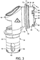
- supply apparatus 6 can be said to include a connector 36, a swivel element 38, an exhalation plate 40, and a closure 42.
- Exhalation plate 40 is mounted to connector 36 and has a plurality of holes formed therein through which exhaled gases can flow in a well-known manner.
- Closure 42 is likewise mountable on connector 36 and has an atmospheric port 44 formed therein to allow the patient to inhale if source of breathable gases 4 should fail for whatever reason.
- Swivel element 38 is rotatably received on connector 36 and permits connector 36 and the tube that extends between supply apparatus 6 and source of breathable gases 4 to be pivotable with respect to one another.
- connector 36 can be said to include a support apparatus 48 and a connection apparatus 52 that are connected together.
- cushion 12 is mountable to connection apparatus 50
- frame 14 is mountable to support apparatus 48.
- cushion 12 and headgear 8 are both mounted to connector 36.
- headgear 8 and cushion 12 are both actually movably mounted to connector 36. That is, connector 36 is pivotable with respect to headgear 8 and cushion 12.
- connector 36 is also pivotable with respect to swivel element 38 and the tube that connects swivel element 38 with source of breathable gas 4, the movability of connector 36 with the other elements to which it is connected promotes a high degree of comfort to the patient during use of patient interface 2.
- Support apparatus 48 can be said to include a support element 52, a mounting apparatus 62, and a swivel base 64.
- a flow passage 60 is formed within support apparatus 48 and carried the flow of breathable gases from source of breathable gases 4 to cushion 12.
- Support element 52 is generally elbow-shaped and has mounting apparatus 62 disposed at one end thereof and has swivel base 64 disposed at another end thereof.
- Swivel base 64 includes a plurality of latches 66 that pivotably retain swivel element movably disposed on swivel base 64.
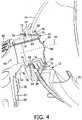
- Support apparatus 48 can be further said to include an annular split washer 54 that is depicted in generally in FIG. 2 and that is cooperable with mounting apparatus 62. More particularly, mounting apparatus 62 can be said to have an annular channel 68 formed thereon, and split washer 54 has a radial split 56 formed therein which enables split washer 54 to be received in channel 68, as is depicted generally in FIG. 4 .
- Split washer 54 serves as a brace element that retains frame 14 situated on connector 36.
- mounting apparatus 62 further has a ledge 72 formed thereon which, in the exemplary embodiment depicted herein, is of an annular shape.
- the region of mounting apparatus 62 that extends between channel 68 and ledge 72 is in the form of an annular boss 74.
- frame 14 can be said to include a lip 76 adjacent opening 16, and lip 76 can be said to be the region of frame 14 peripheral to opening 16.
- connection apparatus 50 is disposed on support apparatus 48 adjacent mounting apparatus 62.
- Connection apparatus 50 can be said to include an engagement element 78 mounted on mounting apparatus 62 and a retention apparatus 80 mounted on engagement element 78 at an end thereof opposite mounting apparatus 62.
- Engagement element 78 includes an outer engagement surface 84 that is of a substantially frusto-conic configuration.
- Engagement surface 84 is structured to receive against it seal surface 30 of seal element 28 of cushion 12, it being reiterated that seal surface 30 likewise has a frusto-conic shape.
- the engagement of engagement surface 84 and seal surface 30 is depicted generally in FIG. 4 .
- retention apparatus 80 includes a plurality of retention elements 86 that that protrude outwardly from engagement surface 84 in a direction generally away from axis 70.
- Retention elements 86 each include a retention surface 88 that faces in a direction generally toward support apparatus 48.
- retention surfaces 88 of retention elements 86 are engaged with abutment surface 32 of seal element 28 when seal surface 30 is received against engagement surface 84. This is the scenario depicted generally in FIG. 4 despite the slight spacing depicted between engagement surface 84 and seal surface 30 which is provided merely for purposes of clarity of disclosure. It can be understood from FIG.
- Retention apparatus 80 retains cushion 12 on engagement element 78 and thus on connector 36 in a fashion that promotes the reliable and leak-resistant provision of the flow of breathable gas to the patient. It is also noted that the retention of seal element 28 between engagement surface 84 and retention surfaces 88 resists axial movement of cushion 12 along axis 70 without resist pivoting movement of cushion 12 about axis 70. Thus, while connection apparatus 50 retains cushion 12 mounted to connector 36, cushion 12 and connector 36 are nevertheless advantageously pivotable about axis 70 with respect to one another.
- cushion 12 can be removed from patient interface 2 by the patient pulling cushion 12 in a direction along axis 70 and generally away from frame 14. In so doing, seal element 28 slides along retention surfaces 88 until it fully clears connection apparatus 50 and can be removed from connector 36. Cushion 12 can then be washed, replaced, etc. as needed by the user. Still further advantageously, when cushion 12 is returned to connector 36, seal element 28 slides over retention elements 86 until seal surface 30 engages engagement surface 84 and retention surfaces 88 engage abutment surface 32, and such engagements occur more or less simultaneously. Such resultant engagement among the aforementioned surfaces provides a desirable tactile and audible feedback that is detectable by the patient and which confirms to the patient that cushion 12 is properly installed on patient interface 2.
- engagement surface 84 is more expressly depicted in FIG. 5 , and it is understood that seal surface 30 is correspondingly shaped in order to sealingly engage engagement surface 84.
- engagement surface 84 is oriented at an angle represented generally at the numeral 92 with respect to the inner surface of engagement element 78 adjacent flow passage 60 and thus likewise with respect to axis 70.
- An angle 92 of approximately five degrees provides a good balance between proving a reliable seal between seal surface 30 and engagement surface 84 while permitting cushion 12 and connector 36 to be pivotable with respect to one another. It is understood that in other embodiments angles greater and lesser than five degrees can be employed without departing from the present concept.
- connection apparatus 50 for pivotably holding cushion 12 on connector 36 i.e., an engagement element having a frusto-conic engagement surface in combination with a set of retention elements, could also be used in place of mounting apparatus 62 as an alternative system for pivotably mounting frame 14 and thus headgear 8 to connector 36.
- connector 36 enables headgear 8 and cushion 12 to be pivotable with respect thereto, thus increasing the comfort of patient interface 2, while maintaining a reliable seal between cushion 12 and connector 36.
- This advantageously increases the reliability with which the flow of breathable gases is provided to the patient.
- cushion 12 is easily removable and replaceable by the patient, and such replacement is accompanied by audible and tactile feedback to the patient, all of which are desirable.
- any reference signs placed between parentheses shall not be construed as limiting the claim.
- the word “comprising” or “including” does not exclude the presence of elements or steps other than those listed in a claim.
- several of these means may be embodied by one and the same item of hardware.
- the word “a” or “an” preceding an element does not exclude the presence of a plurality of such elements.
- any device claim enumerating several means several of these means may be embodied by one and the same item of hardware.
- the mere fact that certain elements are recited in mutually different dependent claims does not indicate that these elements cannot be used in combination.
Claims (12)
- Steckverbinder (36), der ausgestaltet ist, um in einer Patientenschnittstelle (2) eingesetzt zu werden, die ausgestaltet ist, um einen Fluss atembaren Gases zu einem Luftweg eines Patienten bereitzustellen, wobei die Patientenschnittstelle ein federndes Kissen (12) hat, das ausgestaltet ist, um mit dem Gesicht des Patienten einzugreifen, wobei der Steckverbinder (36) Folgendes umfasst:ein Traggerät (48), das ausgestaltet ist, um mit einer Quelle atembaren Gases (4) verbunden zu sein, wobei das Traggerät (48) ferner ein Stützelement (52) umfasst, das ellbogenförmig ist und in dem eine Flusspassage (60) gebildet ist, die ausgestaltet ist, um den Fluss atembaren Gases zu liefern;ein Verbindungsgerät (50), das auf dem Traggerät (48) angeordnet und ausgestaltet ist, um in das Kissen einzugreifen;wobei das Verbindungsgerät (50) ein Eingriffselement (78) umfasst, unddas Eingriffselement (78) eine frustokonische Eingriffsfläche (84) hat, die ausgestaltet ist, um gegen sich mindestens einen Abschnitt des Kissens aufzunehmen,dadurch gekennzeichnet, dass der Steckverbinder (36) ferner ein Haltegerät (80) umfasst, das mindestens ein erstes Halteelement (86) umfasst, das von der frustokonischen Eingriffsfläche (84) auswärts vorsteht und ausgestaltet ist, um in das Kissen einzugreifen und mindestens den Abschnitt des Kissens in einem Zustand gegen die Eingriffsfläche (84) aufgenommen zurückzuhalten.
- Steckverbinder nach Anspruch 1, wobei das mindestens erste Halteelement (86) auf dem Eingriffselement (78) angeordnet ist.
- Steckverbinder nach Anspruch 1, wobei das Haltegerät eine Vielzahl von Halteelementen (86) umfasst, die voneinander beabstandet und um ein Ende des Eingriffselements (78), dem Traggerät (48) entgegengesetzt, angeordnet sind.
- Steckverbinder nach Anspruch 3, wobei die Vielzahl von Halteelementen (86) jeweils von der Eingriffsfläche auswärts vorsteht und jeweils eine Haltefläche (88) hat, die in eine Richtung im Allgemeinen zu dem Traggerät (48) zeigt.
- Steckverbinder nach Anspruch 1, wobei das Traggerät (48) ein Verstrebungselement (54) umfasst, das ausgestaltet ist, um in einen Rahmen der Patientenschnittstelle, der ausgestaltet ist, um mit dem Kopf des Patienten verbunden zu sein, einzugreifen.
- Steckverbinder nach Anspruch 5, wobei das Verstrebungselement (54) im Wesentlichen ringförmig und ausgestaltet ist, um in den Rahmen in einem Bereich (76) umfänglich zu einer im Wesentlichen kreisförmigen Öffnung, die in dem Rahmen gebildet ist, einzugreifen.
- Steckverbinder nach Anspruch 6, wobei das Traggerät (48) ferner einen ringförmigen Kanal (68) hat, der darauf gebildet ist, der ausgestaltet ist, um das Verstrebungselement (54) aufzunehmen.
- Steckverbinder nach Anspruch 7, wobei das Traggerät (48) ferner eine Leiste (72), die auf ihm gebildet ist, umfasst, wobei die Leiste (72) und das Verstrebungselement (54) ausgestaltet sind, um zwischen ihnen den Bereich des Rahmens umfänglich zu der Öffnung zurückzuhalten.
- Steckverbinder nach Anspruch 6, wobei das Traggerät (48) ausgestaltet ist, um bewegbar sowohl mit dem Rahmen als auch mit dem Kissen verbunden zu sein.
- Patientenschnittstelle (2), die den Steckverbinder nach Anspruch 1 umfasst und ferner ein federndes Kissen (12) umfasst, das auf dem Steckverbinder (36) angeordnet ist, und das ausgestaltet ist, um in das Gesicht eines Patienten einzugreifen, wobei die Patientenschnittfläche (2) ausgestaltet ist, um einen Fluss atembaren Gases zu einem Luftweg des Patienten bereitzustellen.
- Patientenschnittstelle nach Anspruch 10, wobei das Kissen (12) ein Dichtelement (28) umfasst, das eine frustokonische Abdichtfläche (30) hat, die in die Eingriffsfläche eingreifen kann, wobei das Haltegerät in das Dichtelement (28) eingreift, wenn die Dichtfläche (30 in die Eingriffsfläche (84) eingreift.
- Patientenschnittstelle nach Anspruch 11, wobei das Dichtelement (28) eine ringförmige Anschlagfläche (32) an einem seiner Enden hat, wobei das Haltegerät in die Anschlagfläche (32) eingreift, wenn die Dichtfläche in die Eingriffsfläche (84) eingreift.
Applications Claiming Priority (2)
| Application Number | Priority Date | Filing Date | Title |
|---|---|---|---|
| US201161556320P | 2011-11-07 | 2011-11-07 | |
| PCT/IB2012/056175 WO2013068911A1 (en) | 2011-11-07 | 2012-11-06 | Patient interface with snap-fit connector |
Publications (2)
| Publication Number | Publication Date |
|---|---|
| EP2747819A1 EP2747819A1 (de) | 2014-07-02 |
| EP2747819B1 true EP2747819B1 (de) | 2017-10-04 |
Family
ID=47192056
Family Applications (1)
| Application Number | Title | Priority Date | Filing Date |
|---|---|---|---|
| EP12787906.2A Active EP2747819B1 (de) | 2011-11-07 | 2012-11-06 | Patientenschnittstelle mit schnappbefestigung |
Country Status (4)
| Country | Link |
|---|---|
| US (1) | US9687620B2 (de) |
| EP (1) | EP2747819B1 (de) |
| CN (1) | CN103930149B (de) |
| WO (1) | WO2013068911A1 (de) |
Families Citing this family (30)
| Publication number | Priority date | Publication date | Assignee | Title |
|---|---|---|---|---|
| US10603456B2 (en) | 2011-04-15 | 2020-03-31 | Fisher & Paykel Healthcare Limited | Interface comprising a nasal sealing portion |
| CN106823090A (zh) | 2011-04-15 | 2017-06-13 | 费雪派克医疗保健有限公司 | 包括收卷式鼻梁部分的接口 |
| WO2014038959A1 (en) | 2012-09-04 | 2014-03-13 | Fisher & Paykel Healthcare Limited | Valsalva mask |
| USD751188S1 (en) | 2013-03-27 | 2016-03-08 | ResMes Limited | Patient interface |
| USD787659S1 (en) * | 2013-09-24 | 2017-05-23 | 3M Innovative Properties Company | Respirator with face seal flexing region |
| USD740932S1 (en) * | 2013-09-24 | 2015-10-13 | 3M Innovative Properties Company | Respirator with raised face seal flexing region |
| EP3068477B1 (de) * | 2013-11-11 | 2017-10-11 | Koninklijke Philips N.V. | Einrastbarer ellbogen für patientenschnittstellenmaske |
| US10589049B2 (en) | 2013-12-18 | 2020-03-17 | Koninklijke Philips N.V. | Fluid connector with exhaust valve |
| CN103893887B (zh) * | 2014-04-16 | 2015-11-25 | 北京怡和嘉业医疗科技有限公司 | 用于呼吸面罩的弯管插拔装置以及呼吸面罩 |
| US10058672B2 (en) * | 2014-05-21 | 2018-08-28 | Atom Medical Corporation | Gas supply mask apparatus |
| WO2016016856A1 (en) * | 2014-07-31 | 2016-02-04 | Koninklijke Philips N.V. | Fluid coupling conduit for a patient interface device |
| JP7117103B2 (ja) | 2014-08-25 | 2022-08-12 | フィッシャー アンド ペイケル ヘルスケア リミテッド | 呼吸マスクおよび関連部分、構成要素または部分組立体 |
| USD782031S1 (en) | 2015-09-25 | 2017-03-21 | Fisher & Paykel Healthcare Limited | Face mask cushion and frame assembly |
| USD828917S1 (en) | 2015-09-25 | 2018-09-18 | Fisher & Paykel Healthcare Limited | Vent diffuser |
| USD784516S1 (en) | 2015-09-25 | 2017-04-18 | Fisher & Paykel Healthcare Limited | Face mask frame |
| USD790054S1 (en) * | 2015-09-25 | 2017-06-20 | Fisher & Paykel Healthcare Limitied | Swivel connector |
| USD784515S1 (en) | 2015-09-25 | 2017-04-18 | Fisher & Paykel Healthcare Limited | Headgear |
| USD800895S1 (en) | 2015-09-25 | 2017-10-24 | Fisher & Paykel Healthcare Limited | Face mask cushion |
| USD782030S1 (en) | 2015-09-25 | 2017-03-21 | Fisher & Paykel Healthcare Limited | Face mask |
| USD882066S1 (en) | 2016-05-13 | 2020-04-21 | Fisher & Paykel Healthcare Limited | Frame for a breathing mask |
| USD814020S1 (en) * | 2016-09-06 | 2018-03-27 | Fisher & Paykel Healthcare Limited | Face mask frame for a respiratory interface |
| USD809649S1 (en) * | 2016-09-06 | 2018-02-06 | Fisher & Paykel Healthcare Limited | Face mask frame for a respiratory interface |
| USD821569S1 (en) | 2016-09-06 | 2018-06-26 | Fisher & Paykel Healthcare Limited | Face mask frame for a respiratory interface |
| USD809132S1 (en) * | 2016-09-06 | 2018-01-30 | Fish & Paykel Healthcare Limited | Face mask frame for a respiratory interface |
| USD824020S1 (en) | 2017-02-23 | 2018-07-24 | Fisher & Paykel Healthcare Limited | Cushion assembly for breathing mask assembly |
| USD823454S1 (en) | 2017-02-23 | 2018-07-17 | Fisher & Paykel Healthcare Limited | Cushion assembly for breathing mask assembly |
| USD823455S1 (en) | 2017-02-23 | 2018-07-17 | Fisher & Paykel Healthcare Limited | Cushion assembly for breathing mask assembly |
| US20180361093A1 (en) * | 2017-06-19 | 2018-12-20 | Loewenstein Medical Technology S.A. | Breathing mask interface with small required operating force |
| US11173268B2 (en) * | 2017-12-22 | 2021-11-16 | ResMed Pty Ltd | Conduit headgear connector for patient interface |
| CA3176805A1 (en) * | 2021-07-02 | 2023-01-02 | Fisher & Paykel Healthcare Limited | Mask assemblies for respiratory therapy |
Citations (2)
| Publication number | Priority date | Publication date | Assignee | Title |
|---|---|---|---|---|
| EP2741802A1 (de) * | 2011-08-10 | 2014-06-18 | Fisher&Paykel Healthcare Limited | Leitungskupplung für eine patientenbeatmungsvorrichtung |
| EP2741666A1 (de) * | 2011-08-09 | 2014-06-18 | P3 Medical Limited | Sauerstoffmaske |
Family Cites Families (19)
| Publication number | Priority date | Publication date | Assignee | Title |
|---|---|---|---|---|
| US5577693A (en) * | 1995-01-11 | 1996-11-26 | Children's Medical Center Corporation | Anesthesia circuit stand |
| US5676133A (en) * | 1995-06-14 | 1997-10-14 | Apotheus Laboratories, Inc. | Expiratory scavenging method and apparatus and oxygen control system for post anesthesia care patients |
| AUPP855099A0 (en) * | 1999-02-09 | 1999-03-04 | Resmed Limited | Gas delivery connection assembly |
| DE29721766U1 (de) * | 1997-12-10 | 1998-02-05 | Scheu Rolf Rainer | Anschlußstück für die Atemgasversorgung eines Patienten |
| US6467483B1 (en) * | 1999-07-28 | 2002-10-22 | Respironics, Inc. | Respiratory mask |
| AUPS192602A0 (en) | 2002-04-23 | 2002-05-30 | Resmed Limited | Nasal mask |
| NZ573226A (en) * | 2002-09-06 | 2010-07-30 | Resmed Ltd | Elbow for respiratory mask assembly |
| NZ578600A (en) | 2003-05-02 | 2011-02-25 | Resmed Ltd | A mask system for apnea vent holes in flexible shell and cushion as integral unit |
| AU2003902098A0 (en) * | 2003-05-02 | 2003-05-22 | Resmed Limited | A mask system |
| CN2635116Y (zh) | 2003-06-25 | 2004-08-25 | 王常有 | 无创氧气面罩 |
| JP4975611B2 (ja) * | 2004-04-09 | 2012-07-11 | レスメド・リミテッド | 鼻用アセンブリ |
| US7021312B2 (en) * | 2004-07-08 | 2006-04-04 | Cannon James L | Assisted breathing device and method of wearing same |
| US7726309B2 (en) * | 2006-06-05 | 2010-06-01 | Ric Investments, Llc | Flexible connector |
| US8342181B2 (en) * | 2006-06-16 | 2013-01-01 | Resmed Limited | Elbow assembly |
| NZ569226A (en) * | 2007-06-22 | 2010-02-26 | Resmed Ltd | Flexible forehead support |
| EP2259826B1 (de) | 2008-03-04 | 2020-12-16 | ResMed Pty Ltd | Maskenanordnung |
| US8950403B2 (en) | 2008-03-04 | 2015-02-10 | Resmed Limited | Mask system and method for constructing the same |
| CN101543656B (zh) * | 2008-03-24 | 2011-08-24 | 新广业股份有限公司 | 方便拆组的呼吸面罩 |
| US9149593B2 (en) * | 2009-05-29 | 2015-10-06 | Resmed Limited | Nasal mask system |
-
2012
- 2012-11-06 WO PCT/IB2012/056175 patent/WO2013068911A1/en active Application Filing
- 2012-11-06 CN CN201280054816.1A patent/CN103930149B/zh active Active
- 2012-11-06 EP EP12787906.2A patent/EP2747819B1/de active Active
- 2012-11-06 US US14/356,255 patent/US9687620B2/en active Active
Patent Citations (2)
| Publication number | Priority date | Publication date | Assignee | Title |
|---|---|---|---|---|
| EP2741666A1 (de) * | 2011-08-09 | 2014-06-18 | P3 Medical Limited | Sauerstoffmaske |
| EP2741802A1 (de) * | 2011-08-10 | 2014-06-18 | Fisher&Paykel Healthcare Limited | Leitungskupplung für eine patientenbeatmungsvorrichtung |
Also Published As
| Publication number | Publication date |
|---|---|
| CN103930149A (zh) | 2014-07-16 |
| EP2747819A1 (de) | 2014-07-02 |
| WO2013068911A1 (en) | 2013-05-16 |
| US9687620B2 (en) | 2017-06-27 |
| US20140305433A1 (en) | 2014-10-16 |
| CN103930149B (zh) | 2016-08-17 |
Similar Documents
| Publication | Publication Date | Title |
|---|---|---|
| EP2747819B1 (de) | Patientenschnittstelle mit schnappbefestigung | |
| US8342181B2 (en) | Elbow assembly | |
| US8701667B1 (en) | Patient interface device with limited support area on the face | |
| US20140311496A1 (en) | Patient interface having headgear post for clip or strap | |
| US8746249B2 (en) | Patient interface device having cam wheel adjustment mechanism | |
| US20140261435A1 (en) | Cushion for patient interface with localized region of reduced stiffness | |
| US20120318274A1 (en) | Replaceable nasal pillow | |
| US20120318271A1 (en) | Replaceable nasal pillow kit | |
| US20150246199A1 (en) | Articulating full face mask | |
| US10828451B2 (en) | Passive nose bridge pressure distributing insert | |
| RU2635467C2 (ru) | Педиатрическая общелицевая маска | |
| JP2016501089A (ja) | 呼吸インターフェースデバイス用のモーションスタビライザシステム | |
| EP2474335A1 (de) | Verbessertes Kissen für Gesichtsmaske zur Behandlung von Schlafstörungen | |
| US11554234B2 (en) | Breathing assistance apparatus | |
| US20140305438A1 (en) | Patient interface device with cushion sealing arrangement | |
| US20140069434A1 (en) | Lever arm cushion attachment mechanism | |
| US9821132B2 (en) | Patient interface device including an adjustable forehead support having a vertical wheel drive mechanism | |
| EP2478925B1 (de) | Verbessertes Membrankissen für Gesichtsmaske zur Behandlung von Schlafstörungen | |
| WO2016108112A1 (en) | Rigid contoured ribbon and variable spring sealing |
Legal Events
| Date | Code | Title | Description |
|---|---|---|---|
| PUAI | Public reference made under article 153(3) epc to a published international application that has entered the european phase |
Free format text: ORIGINAL CODE: 0009012 |
|
| 17P | Request for examination filed |
Effective date: 20140324 |
|
| AK | Designated contracting states |
Kind code of ref document: A1 Designated state(s): AL AT BE BG CH CY CZ DE DK EE ES FI FR GB GR HR HU IE IS IT LI LT LU LV MC MK MT NL NO PL PT RO RS SE SI SK SM TR |
|
| DAX | Request for extension of the european patent (deleted) | ||
| RIN1 | Information on inventor provided before grant (corrected) |
Inventor name: ROTHERMEL, JUSTIN EDWARD |
|
| 17Q | First examination report despatched |
Effective date: 20160830 |
|
| GRAP | Despatch of communication of intention to grant a patent |
Free format text: ORIGINAL CODE: EPIDOSNIGR1 |
|
| INTG | Intention to grant announced |
Effective date: 20170424 |
|
| GRAS | Grant fee paid |
Free format text: ORIGINAL CODE: EPIDOSNIGR3 |
|
| GRAA | (expected) grant |
Free format text: ORIGINAL CODE: 0009210 |
|
| AK | Designated contracting states |
Kind code of ref document: B1 Designated state(s): AL AT BE BG CH CY CZ DE DK EE ES FI FR GB GR HR HU IE IS IT LI LT LU LV MC MK MT NL NO PL PT RO RS SE SI SK SM TR |
|
| REG | Reference to a national code |
Ref country code: GB Ref legal event code: FG4D |
|
| REG | Reference to a national code |
Ref country code: CH Ref legal event code: EP |
|
| REG | Reference to a national code |
Ref country code: AT Ref legal event code: REF Ref document number: 933428 Country of ref document: AT Kind code of ref document: T Effective date: 20171015 |
|
| REG | Reference to a national code |
Ref country code: IE Ref legal event code: FG4D |
|
| REG | Reference to a national code |
Ref country code: DE Ref legal event code: R096 Ref document number: 602012038177 Country of ref document: DE |
|
| REG | Reference to a national code |
Ref country code: FR Ref legal event code: PLFP Year of fee payment: 6 |
|
| REG | Reference to a national code |
Ref country code: NL Ref legal event code: MP Effective date: 20171004 |
|
| REG | Reference to a national code |
Ref country code: LT Ref legal event code: MG4D |
|
| REG | Reference to a national code |
Ref country code: AT Ref legal event code: MK05 Ref document number: 933428 Country of ref document: AT Kind code of ref document: T Effective date: 20171004 |
|
| PG25 | Lapsed in a contracting state [announced via postgrant information from national office to epo] |
Ref country code: NL Free format text: LAPSE BECAUSE OF FAILURE TO SUBMIT A TRANSLATION OF THE DESCRIPTION OR TO PAY THE FEE WITHIN THE PRESCRIBED TIME-LIMIT Effective date: 20171004 |
|
| PG25 | Lapsed in a contracting state [announced via postgrant information from national office to epo] |
Ref country code: FI Free format text: LAPSE BECAUSE OF FAILURE TO SUBMIT A TRANSLATION OF THE DESCRIPTION OR TO PAY THE FEE WITHIN THE PRESCRIBED TIME-LIMIT Effective date: 20171004 Ref country code: ES Free format text: LAPSE BECAUSE OF FAILURE TO SUBMIT A TRANSLATION OF THE DESCRIPTION OR TO PAY THE FEE WITHIN THE PRESCRIBED TIME-LIMIT Effective date: 20171004 Ref country code: NO Free format text: LAPSE BECAUSE OF FAILURE TO SUBMIT A TRANSLATION OF THE DESCRIPTION OR TO PAY THE FEE WITHIN THE PRESCRIBED TIME-LIMIT Effective date: 20180104 Ref country code: SE Free format text: LAPSE BECAUSE OF FAILURE TO SUBMIT A TRANSLATION OF THE DESCRIPTION OR TO PAY THE FEE WITHIN THE PRESCRIBED TIME-LIMIT Effective date: 20171004 Ref country code: LT Free format text: LAPSE BECAUSE OF FAILURE TO SUBMIT A TRANSLATION OF THE DESCRIPTION OR TO PAY THE FEE WITHIN THE PRESCRIBED TIME-LIMIT Effective date: 20171004 |
|
| PG25 | Lapsed in a contracting state [announced via postgrant information from national office to epo] |
Ref country code: AT Free format text: LAPSE BECAUSE OF FAILURE TO SUBMIT A TRANSLATION OF THE DESCRIPTION OR TO PAY THE FEE WITHIN THE PRESCRIBED TIME-LIMIT Effective date: 20171004 Ref country code: BG Free format text: LAPSE BECAUSE OF FAILURE TO SUBMIT A TRANSLATION OF THE DESCRIPTION OR TO PAY THE FEE WITHIN THE PRESCRIBED TIME-LIMIT Effective date: 20180104 Ref country code: RS Free format text: LAPSE BECAUSE OF FAILURE TO SUBMIT A TRANSLATION OF THE DESCRIPTION OR TO PAY THE FEE WITHIN THE PRESCRIBED TIME-LIMIT Effective date: 20171004 Ref country code: IS Free format text: LAPSE BECAUSE OF FAILURE TO SUBMIT A TRANSLATION OF THE DESCRIPTION OR TO PAY THE FEE WITHIN THE PRESCRIBED TIME-LIMIT Effective date: 20180204 Ref country code: LV Free format text: LAPSE BECAUSE OF FAILURE TO SUBMIT A TRANSLATION OF THE DESCRIPTION OR TO PAY THE FEE WITHIN THE PRESCRIBED TIME-LIMIT Effective date: 20171004 Ref country code: GR Free format text: LAPSE BECAUSE OF FAILURE TO SUBMIT A TRANSLATION OF THE DESCRIPTION OR TO PAY THE FEE WITHIN THE PRESCRIBED TIME-LIMIT Effective date: 20180105 Ref country code: HR Free format text: LAPSE BECAUSE OF FAILURE TO SUBMIT A TRANSLATION OF THE DESCRIPTION OR TO PAY THE FEE WITHIN THE PRESCRIBED TIME-LIMIT Effective date: 20171004 |
|
| REG | Reference to a national code |
Ref country code: DE Ref legal event code: R097 Ref document number: 602012038177 Country of ref document: DE |
|
| PG25 | Lapsed in a contracting state [announced via postgrant information from national office to epo] |
Ref country code: EE Free format text: LAPSE BECAUSE OF FAILURE TO SUBMIT A TRANSLATION OF THE DESCRIPTION OR TO PAY THE FEE WITHIN THE PRESCRIBED TIME-LIMIT Effective date: 20171004 Ref country code: DK Free format text: LAPSE BECAUSE OF FAILURE TO SUBMIT A TRANSLATION OF THE DESCRIPTION OR TO PAY THE FEE WITHIN THE PRESCRIBED TIME-LIMIT Effective date: 20171004 Ref country code: MC Free format text: LAPSE BECAUSE OF FAILURE TO SUBMIT A TRANSLATION OF THE DESCRIPTION OR TO PAY THE FEE WITHIN THE PRESCRIBED TIME-LIMIT Effective date: 20171004 Ref country code: SK Free format text: LAPSE BECAUSE OF FAILURE TO SUBMIT A TRANSLATION OF THE DESCRIPTION OR TO PAY THE FEE WITHIN THE PRESCRIBED TIME-LIMIT Effective date: 20171004 Ref country code: CZ Free format text: LAPSE BECAUSE OF FAILURE TO SUBMIT A TRANSLATION OF THE DESCRIPTION OR TO PAY THE FEE WITHIN THE PRESCRIBED TIME-LIMIT Effective date: 20171004 Ref country code: CH Free format text: LAPSE BECAUSE OF NON-PAYMENT OF DUE FEES Effective date: 20171130 Ref country code: LI Free format text: LAPSE BECAUSE OF NON-PAYMENT OF DUE FEES Effective date: 20171130 |
|
| PLBE | No opposition filed within time limit |
Free format text: ORIGINAL CODE: 0009261 |
|
| STAA | Information on the status of an ep patent application or granted ep patent |
Free format text: STATUS: NO OPPOSITION FILED WITHIN TIME LIMIT |
|
| PG25 | Lapsed in a contracting state [announced via postgrant information from national office to epo] |
Ref country code: PL Free format text: LAPSE BECAUSE OF FAILURE TO SUBMIT A TRANSLATION OF THE DESCRIPTION OR TO PAY THE FEE WITHIN THE PRESCRIBED TIME-LIMIT Effective date: 20171004 Ref country code: SM Free format text: LAPSE BECAUSE OF FAILURE TO SUBMIT A TRANSLATION OF THE DESCRIPTION OR TO PAY THE FEE WITHIN THE PRESCRIBED TIME-LIMIT Effective date: 20171004 Ref country code: LU Free format text: LAPSE BECAUSE OF NON-PAYMENT OF DUE FEES Effective date: 20171106 Ref country code: IT Free format text: LAPSE BECAUSE OF FAILURE TO SUBMIT A TRANSLATION OF THE DESCRIPTION OR TO PAY THE FEE WITHIN THE PRESCRIBED TIME-LIMIT Effective date: 20171004 Ref country code: RO Free format text: LAPSE BECAUSE OF FAILURE TO SUBMIT A TRANSLATION OF THE DESCRIPTION OR TO PAY THE FEE WITHIN THE PRESCRIBED TIME-LIMIT Effective date: 20171004 |
|
| REG | Reference to a national code |
Ref country code: BE Ref legal event code: MM Effective date: 20171130 |
|
| REG | Reference to a national code |
Ref country code: IE Ref legal event code: MM4A |
|
| 26N | No opposition filed |
Effective date: 20180705 |
|
| GBPC | Gb: european patent ceased through non-payment of renewal fee |
Effective date: 20180104 |
|
| PG25 | Lapsed in a contracting state [announced via postgrant information from national office to epo] |
Ref country code: MT Free format text: LAPSE BECAUSE OF NON-PAYMENT OF DUE FEES Effective date: 20171106 |
|
| PG25 | Lapsed in a contracting state [announced via postgrant information from national office to epo] |
Ref country code: IE Free format text: LAPSE BECAUSE OF NON-PAYMENT OF DUE FEES Effective date: 20171106 |
|
| PG25 | Lapsed in a contracting state [announced via postgrant information from national office to epo] |
Ref country code: BE Free format text: LAPSE BECAUSE OF NON-PAYMENT OF DUE FEES Effective date: 20171130 Ref country code: SI Free format text: LAPSE BECAUSE OF FAILURE TO SUBMIT A TRANSLATION OF THE DESCRIPTION OR TO PAY THE FEE WITHIN THE PRESCRIBED TIME-LIMIT Effective date: 20171004 Ref country code: GB Free format text: LAPSE BECAUSE OF NON-PAYMENT OF DUE FEES Effective date: 20180104 |
|
| PG25 | Lapsed in a contracting state [announced via postgrant information from national office to epo] |
Ref country code: HU Free format text: LAPSE BECAUSE OF FAILURE TO SUBMIT A TRANSLATION OF THE DESCRIPTION OR TO PAY THE FEE WITHIN THE PRESCRIBED TIME-LIMIT; INVALID AB INITIO Effective date: 20121106 |
|
| PG25 | Lapsed in a contracting state [announced via postgrant information from national office to epo] |
Ref country code: CY Free format text: LAPSE BECAUSE OF NON-PAYMENT OF DUE FEES Effective date: 20171004 |
|
| PG25 | Lapsed in a contracting state [announced via postgrant information from national office to epo] |
Ref country code: MK Free format text: LAPSE BECAUSE OF FAILURE TO SUBMIT A TRANSLATION OF THE DESCRIPTION OR TO PAY THE FEE WITHIN THE PRESCRIBED TIME-LIMIT Effective date: 20171004 |
|
| PG25 | Lapsed in a contracting state [announced via postgrant information from national office to epo] |
Ref country code: TR Free format text: LAPSE BECAUSE OF FAILURE TO SUBMIT A TRANSLATION OF THE DESCRIPTION OR TO PAY THE FEE WITHIN THE PRESCRIBED TIME-LIMIT Effective date: 20171004 |
|
| PG25 | Lapsed in a contracting state [announced via postgrant information from national office to epo] |
Ref country code: PT Free format text: LAPSE BECAUSE OF FAILURE TO SUBMIT A TRANSLATION OF THE DESCRIPTION OR TO PAY THE FEE WITHIN THE PRESCRIBED TIME-LIMIT Effective date: 20171004 |
|
| PG25 | Lapsed in a contracting state [announced via postgrant information from national office to epo] |
Ref country code: AL Free format text: LAPSE BECAUSE OF FAILURE TO SUBMIT A TRANSLATION OF THE DESCRIPTION OR TO PAY THE FEE WITHIN THE PRESCRIBED TIME-LIMIT Effective date: 20171004 |
|
| PGFP | Annual fee paid to national office [announced via postgrant information from national office to epo] |
Ref country code: FR Payment date: 20221122 Year of fee payment: 11 Ref country code: DE Payment date: 20220628 Year of fee payment: 11 |