EP2747736B1 - Device and method for filling capsules - Google Patents
Device and method for filling capsules Download PDFInfo
- Publication number
- EP2747736B1 EP2747736B1 EP20120748495 EP12748495A EP2747736B1 EP 2747736 B1 EP2747736 B1 EP 2747736B1 EP 20120748495 EP20120748495 EP 20120748495 EP 12748495 A EP12748495 A EP 12748495A EP 2747736 B1 EP2747736 B1 EP 2747736B1
- Authority
- EP
- European Patent Office
- Prior art keywords
- feeding
- blocking
- products
- product
- end portion
- Prior art date
- Legal status (The legal status is an assumption and is not a legal conclusion. Google has not performed a legal analysis and makes no representation as to the accuracy of the status listed.)
- Active
Links
Images




Classifications
-
- A—HUMAN NECESSITIES
- A61—MEDICAL OR VETERINARY SCIENCE; HYGIENE
- A61J—CONTAINERS SPECIALLY ADAPTED FOR MEDICAL OR PHARMACEUTICAL PURPOSES; DEVICES OR METHODS SPECIALLY ADAPTED FOR BRINGING PHARMACEUTICAL PRODUCTS INTO PARTICULAR PHYSICAL OR ADMINISTERING FORMS; DEVICES FOR ADMINISTERING FOOD OR MEDICINES ORALLY; BABY COMFORTERS; DEVICES FOR RECEIVING SPITTLE
- A61J3/00—Devices or methods specially adapted for bringing pharmaceutical products into particular physical or administering forms
- A61J3/07—Devices or methods specially adapted for bringing pharmaceutical products into particular physical or administering forms into the form of capsules or similar small containers for oral use
- A61J3/071—Devices or methods specially adapted for bringing pharmaceutical products into particular physical or administering forms into the form of capsules or similar small containers for oral use into the form of telescopically engaged two-piece capsules
- A61J3/074—Filling capsules; Related operations
Definitions
- the present invention relates to a filling device and a method for filling capsules with products, in particular solid forms for pharmaceutical, alimentary and/or cosmetic use.
- the invention is particularly applicable in an automatic machine for packaging capsules for pharmaceutical, alimentary and/or cosmetic use.
- European patent EP 0 825 846 B1 shows, for example, an automatic machine for packaging gelatine capsules of bottom-lid type, each including a tablet.
- the automatic machine shown in EP 0 825 846 is intermittently movable and includes groups of housings moved to cooperate with a plurality of stations in succession: a first station that feeds the bottoms of the capsules to respective housings; a second station that feeds a tablet within a respective bottom, a third station that feeds the lids of the capsules above a respective tablet; a forth station that checks whether respective bottom, tablet and lid are present in the housings; a fifth station that closes bottom and lid with interposed tablet; a sixth station that expels the capsules containing the tablet and rejects, by means of a rejection device, the capsules found faulty.
- the second station that feeds the tablet within the bottom of the capsule includes a vertical store within which the capsules are aligned.
- a pneumatic system for retaining the capsules includes two suction holes arranged transversally to the store and cooperating with a transferring drawer, movable horizontally for retaining and transferring one tablet at the time from the store to the bottom of the capsule.
- the suction holes are arranged with respect to the transferring drawer at a height such as a proper functioning of the station is assured, even when broken tablets are present.
- the pneumatic system in cooperation with the transferring drawer guarantees not to break all of the capsules that follow a first broken tablet during transfer from the store to the bottom of the capsule.
- it is checked, by means of sensors connected to movable rods, whether bottom, tablet and lid are present, and whether the tablet is entire or damaged.
- the machine illustrated above achieves excellent results in terms of certainty of checking in case of one tablet per capsule, but it could be ineffective in case of capsules fed with more than one product (tablets, granules, ecc) of relatively small dimensions with respect to relatively large bottoms, because the movable rods might not detect all of the products contained in the bottom. Moreover, the machine results relatively costly and complicated because of the transferring drawer, the movable rods, and the pneumatic system that retains the tablets.
- US 5 329 749 A packaging machines for packaging a predetermined number of tablets into a body of a hard gelatine capsule, comprising a feeding conduit divided in three not-aligned sections, within which the tablets can slide. Between the three sections of the feeding conduit, a carrying plate and a shutter plate are arranged. The carrying plate transfers the tablets from a first section of the feeding conduit to a second section of the feeding conduit. No checking means is disclosed in US 5 329 749 A to check whether or not tablets are properly fed to hard gelatine capsule.
- EP 2 019 040 discloses a filling unit for filling capsules with tablets including a filling disk provided with containing holes adapted to contain a predetermined number of tablets. The filling disk receives the tablets from a counting disk and transfer in rotation the tablets to a capsule body.
- EP 2 019 040 mentions the possibility to provide the filling unit with a displacement sensor, but the overall filling unit results in a relatively costly and complex structure.
- a filling device 1 adapted to fill a bottom 3 of a capsule with one or more products 2.
- FIGS 1 - 7 there is schematically shown the case in which two products 2 of substantially spherical shape are fed within each bottom 3.
- the products 2 may be, for example, tablets, granules, pellets, different types of multiparticulate systems or other solid forms for pharmaceutical, food, and/or cosmetic use.
- the filling device 1 may advantageously be part of an automatic packaging machine of known type, not illustrated, intermittently movable, including groups of housings 4 radially arranged on a moving carousel that moves the housings 4 to cooperate with a plurality of operative stations arranged in succession, among which: a first feeding station for feeding the bottoms 3 to the housings 4; a second filling station including the filling device 1 for feeding the products 2 to the bottoms 3, in particular one or more products 2 per bottom 3; a third feeding station for feeding lids to the housings 4; a forth closing station for closing the bottom 3 with a respective lid to form a capsule filled with one or more products 2; finally, and a fifth expelling station for expelling the filled capsules from the housings 4.
- the automatic packaging machine further includes rejection devices, for rejecting faulty capsules, associated with any one of the stations downstream of the second filling station.
- the filling device 1 includes a feeding conduit 5, adapted to slidingly contain a row 6 of products 2, and a blocking and feeding system 7, for blocking the row 6 of products 2 and feeding a group 8 of products 2, including a predefined number of products 2, to a bottom 3 of the capsule arranged below.
- the group 8 of products 2 may comprise one or more products, for example two, three or more products 2.
- the feeding conduit 5 defines a feeding direction 9 for the products 2 and includes a bottom end portion 15 that slidingly houses, below the row 6 of products 2, the group 8 of aligned products 2.
- the blocking and feeding system 7 is of the escapement type and includes a first blocking and feeding element 10 and a second blocking and feeding element 11.
- the first blocking and feeding element 10 is positioned below the second blocking and feeding element 11.
- the first blocking and feeding element 10 is movable, advantageously onto a horizontal plane, between an operative position, wherein it closes the feeding conduit 5, and an inoperative position, far away from the feeding conduit 5, wherein the feeding conduit 5 at the bottom end portion 15 results inferiorly open.
- the first blocking and feeding element 10 includes a first lamina 12, advantageously flat, arranged below the bottom end portion 15 of the feeding conduit 5.
- the first blocking and feeding element 10, in particular the first lamina 12 is adapted to support and blocking a first product 18 of the group 8 of products 2 and, therefore, all of the products 2 positioned within the feeding conduit 5 above the first product 18.
- the second blocking and feeding element 11 is movable between an operative position, close to the feeding conduit 5, and an inoperative position, far away from the feeding conduit 5.
- the second blocking and feeding element 11 includes a second lamina 13, "L" shaped, adapted to rotate about a fulcrum 14 between the operative position and the inoperative position.
- the second lamina 13 in operative position cooperates with a longitudinal slot 17 achieved in the feeding conduit 5 to block a further product 19 of the row 6 of products 2.
- the row 6 of products 2 results blocked, i.e. the products 2 positioned above the further product 19 result blocked.
- the second lamina 13 do not act onto the products 2 of the group 8 to be fed that are positioned below the row 6.
- the second blocking and feeding element 11, in particular the second lamina 13, is further movable along the feeding direction 9 in order to be suitably positioned along the feeding conduit 5, in such a way that a distance between the first lamina 12 and the second lamina 13 be adjustable. Such distance defines the bottom end portion 15 of the feeding conduit 5 that houses the products 2 of the group 8.
- the distance between the first lamina 12 and the second lamina 13 can be varied and, consequently, the predefined number of products 2 of the group 8 to be fed to the below bottom 3 can be varied.
- the products 2 of the group 8 are housed within the bottom end portion 15, aligned from the first product 18, lowermost positioned, to a last product 20, uppermost positioned at an upper zone 21 of the bottom end portion 15 of the feeding conduit 5, immediately below and in contact with the further product 19.
- the predefined number of products be one, the first product 18 and the last product 20 coincide.
- the filling device 1 further includes a detecting device 16, advantageously a photo detecting device including a photocell 22 of the barrier type, positioned transversally to the feeding conduit 5 at the upper zone 21 of the bottom end portion 15 intended to house the last product 20 of the group 8.
- a detecting device 16 advantageously a photo detecting device including a photocell 22 of the barrier type, positioned transversally to the feeding conduit 5 at the upper zone 21 of the bottom end portion 15 intended to house the last product 20 of the group 8.
- the detecting device 16, in particular the photocell 22, is therefore adapted to detect whether or not the last product 20 of the group 8 is present within the bottom end portion 15 of the feeding conduit 5, or, in other words, whether or not the group 8 consists of the predefined number of products 2.
- the products 2 are slidingly housed within the feeding conduit 5 and, if not retained, are destined to fall by gravity, by verifying whether or not a single product (the last product 20 of the group 8) is present in the upper zone 21, it can be immediately derived whether or not the group 8 of products 2 to be fed to the below bottom 3 of the capsule is complete.
- the filling device 1 detects in an extremely simple, fast and inexpensive, but at the same time extremely reliable, way, not only cases of non-filling, but also partial and incomplete filling (see figures 9 - 11 ), with no need to weight all of the capsules 2 downstream of the forth closing station (100% check weight).
- the detecting device 16 emits a suitable rejection signal to rejection devices for rejecting the below bottom 3 only, or the entire capsule formed by the below bottom 3.
- rejection devices may advantageously be coupled to, or integral with, the same filling device 1, or successive operative stations.
- the detecting device 16, in particular the photocell 22, is advantageously coupled to the second blocking and feeding element 11, in particular to the second lamina 13, and is movable therewith along the feeding direction 9 in order to be suitably positioned along the feeding conduit 5, so as to detect the presence of the last product 20 for any predefined number of products 2 of the group 8.
- the detecting device 16, in particular the photocell 22, is adapted to be positioned immediately below the second lamina 13 for a whatsoever distance between the first blocking and feeding element 10 and the second blocking and feeding element 11, or, in an equivalent manner, for a whatsoever predefined number of products 2 of the group 8.
- the detecting devices 16 may include ultrasound, proximity, or contact sensors adapted to detect the presence of one product 2 in the upper zone 21 of the bottom end portion 15 of the feeding conduit 5 only, or, in other words, the presence of the last product 20 of the group 8 only.
- pneumatic systems may be foresee to promote the fall of the products 2 along the feeding conduit 5 towards the bottom 3 of the capsule.
- More filling devices 1 of the type illustrated may be arranged side by side and mutually integrated in an automatic packaging machine for filling more capsules simultaneously.
- the blocking and feeding system 7 described before achieves an escapement system.
- the first blocking and feeding element 10 and the second blocking and feeding element 11 cooperates in proper phase for blocking and releasing the row 6 of products 2 and defining, blocking and releasing the group 8 of products 2 to be fed to the bottom 3.
- the filling device 1 carries out a filling method including the following steps:
- the method further includes, during the second step, a detecting step to detect, by means of a detecting device 16, advantageously a photo detecting device including a photocell 22, whether the group 6 is complete.
- a detecting step to detect, by means of a detecting device 16, advantageously a photo detecting device including a photocell 22, whether the group 6 is complete.
- the method provides for a detecting step to detect, by means of the detecting means 16, arranged laterally to the feeding conduit 5, at an upper zone 21 of the bottom end portion 15 of the feeding conduit 5 intended to house a last product 20 of the group 8, whether or not such last product 20 is present in such upper zone 21.
- the method provides for detecting whether or not just one single product 2 is present in the upper zone 21 only, with no need to detect other products in other zones of the bottom end portion 15 of the feeding conduit 5.
- the group 8 may comprise one or more products 2, for example two, three, or more products.
- the detecting device 16 detects whether the entire group 8 is fed to the bottom 3 of the capsule.
- the detecting device 16 detects whether or not the group 8 is complete.
- the method further provides for, in case the detecting device 16 detects that the group 8 is absent or incomplete, sending a rejection signal to rejection devices to reject the below bottom 3 only, or the entire capsule formed by the below bottom 3, as it contains a group 8 at least incomplete, even not completely absent, and therefore faulty.
- the rejection devices may be arranged downstream of the filling device 1, for example integrated in any one of the successive operative stations.
- the device and method according to the invention it is therefore possible to identify and reject, as soon as possible in the automatic packaging machine, the capsules that have not been filled, or that have been incompletely filled, without the need to weight all of the capsules exiting the automatic packaging machine, thus the properly filled capsules as well.
- the invention has been illustrated in case the capsules are filled with two products, i.e. in case the group 8 consists of two products, it is possible to carry out the invention even in case the capsule must be filled with a predefined number of products 2 different from two, i.e. in case the group 8 consists of one, three, four, five, or more products 2.
- the second blocking and feeding element 11, in particular the second lamina 13, should be moved and positioned lower than illustrated in case of group 8 consisting of two products 2, at a distance from the first blocking and feeding element 10, in particular the first lamina 12, such as to define a bottom end portion 15 of the feeding conduit 5 adapted to house one product 2 only.
- the capsule should be filled with three or more products 2, i.e. in case the group 8 consists of more than two products 2, the blocking and feeding element 11, in particular the second lamina 13, should be moved and positioned upper than illustrated in case of group 8 consisting of two products 2, at a distance from the first blocking and feeding element, in particular from the first lamina 12, such as to define a bottom end portion 15 of the feeding conduit 5 adapted to house respective three or more products 2.
- the detecting device 16, in particular the photocell 22 is moved downwards, or upwards, respectively, along with the second blocking and feeding element 11 along the feeding direction 9 to check only the upper zone 21 of the bottom end portion 15 of the feeding conduit 5 and to detect whether or not the last product 20 of the group 8 is present.
- FIGS 12 - 15 there is illustrated the filling device 1 of the invention for feeding capsules with products 2 with oblong shape in groups 8 of one single product 2.
- the first product 18 and the last product 20 of the group 8 coincide.
- the further product 19 is blocked by the second blocking and feeding element 11, in particular the second lamina 13, in a position such as to be detected by the detecting device 16, in particular the photocell 22, during the third step of the method of the invention, i.e. when the first blocking and feeding element 10 is in inoperative position to inferiorly open the bottom end portion 15 of the feeding conduit 5 and the second blocking and feeding element 11 is in operative position to block the further product 19.
- the detecting device 16 once a presence of a product 2 (necessarily the further product 19) has been detected during the third step, sends a rejection signal to reject the bottom 3 (or the entire capsule) that has been just filled, as such capsule contains a broken product 2 and thus is faulty.
- the further product 19 would be blocked in such a position that the detecting device 16 would not detect the presence of any products (see for example figure 13 ) and consequently would not emit any rejection signal.
- the detecting device 16 would detect, during the second step, at the upper zone 21, the presence of a product 2, that would be the further product 19 that projects inferiorly, and not the last product 20 of the group 8. Therefore, the capsule that has been just filled will be rejected, without errors, because during the third phase the detecting device 16 would detect the presence of such further product 19.
Landscapes
- Health & Medical Sciences (AREA)
- Chemical & Material Sciences (AREA)
- Medicinal Chemistry (AREA)
- Pharmacology & Pharmacy (AREA)
- Life Sciences & Earth Sciences (AREA)
- Animal Behavior & Ethology (AREA)
- General Health & Medical Sciences (AREA)
- Public Health (AREA)
- Veterinary Medicine (AREA)
- Medical Preparation Storing Or Oral Administration Devices (AREA)
- Signal Processing For Digital Recording And Reproducing (AREA)
- Manufacturing Of Electric Cables (AREA)
- Basic Packing Technique (AREA)
Description
- The present invention relates to a filling device and a method for filling capsules with products, in particular solid forms for pharmaceutical, alimentary and/or cosmetic use.
- The invention is particularly applicable in an automatic machine for packaging capsules for pharmaceutical, alimentary and/or cosmetic use.
- Machines for packaging tablets within hard gelatin capsules are known. European patent
EP 0 825 846 B1 shows, for example, an automatic machine for packaging gelatine capsules of bottom-lid type, each including a tablet. The automatic machine shown inEP 0 825 846 is intermittently movable and includes groups of housings moved to cooperate with a plurality of stations in succession: a first station that feeds the bottoms of the capsules to respective housings; a second station that feeds a tablet within a respective bottom, a third station that feeds the lids of the capsules above a respective tablet; a forth station that checks whether respective bottom, tablet and lid are present in the housings; a fifth station that closes bottom and lid with interposed tablet; a sixth station that expels the capsules containing the tablet and rejects, by means of a rejection device, the capsules found faulty. - The second station that feeds the tablet within the bottom of the capsule includes a vertical store within which the capsules are aligned. A pneumatic system for retaining the capsules includes two suction holes arranged transversally to the store and cooperating with a transferring drawer, movable horizontally for retaining and transferring one tablet at the time from the store to the bottom of the capsule. The suction holes are arranged with respect to the transferring drawer at a height such as a proper functioning of the station is assured, even when broken tablets are present. In other words, the pneumatic system in cooperation with the transferring drawer guarantees not to break all of the capsules that follow a first broken tablet during transfer from the store to the bottom of the capsule. In any case, in the forth station, it is checked, by means of sensors connected to movable rods, whether bottom, tablet and lid are present, and whether the tablet is entire or damaged.
- The machine illustrated above achieves excellent results in terms of certainty of checking in case of one tablet per capsule, but it could be ineffective in case of capsules fed with more than one product (tablets, granules, ecc) of relatively small dimensions with respect to relatively large bottoms, because the movable rods might not detect all of the products contained in the bottom. Moreover, the machine results relatively costly and complicated because of the transferring drawer, the movable rods, and the pneumatic system that retains the tablets.
- There are also known from
US 5 329 749 A packaging machines for packaging a predetermined number of tablets into a body of a hard gelatine capsule, comprising a feeding conduit divided in three not-aligned sections, within which the tablets can slide. Between the three sections of the feeding conduit, a carrying plate and a shutter plate are arranged. The carrying plate transfers the tablets from a first section of the feeding conduit to a second section of the feeding conduit. No checking means is disclosed inUS 5 329 749 A to check whether or not tablets are properly fed to hard gelatine capsule. -
EP 2 019 040EP 2 019 040 - To overcome the above mentioned disadvantages, it is known to omit the movable rods and associated sensors and to weight all of the capsules packaged in the automatic machine in order to check whether or not the capsules have been properly filled, but such solution involves additional costs for a weight checking station and, above all, a reduction in productivity of the machine, as the weighting operations are relatively slow.
- It is an aim of the present invention to fill capsules with products with high productivity, in a relatively simple and inexpensive way, and with guarantee of detecting capsules not properly filled.
- This and other aims are achieved by a filling device according to
claim 1 and by a filling method according toclaim 8. - The invention will be described with reference to the figures, given by way of nonlimiting examples and for illustrative purpose only, wherein:
-
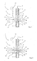
figures 1 - 7 are a schematic illustration of a filling device according to the invention during successive steps of a filling method according to the invention for filling capsules with products; -
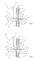
figure 8 is a schematic illustration of the filling device of the invention during a step of the filling method according to the invention in case of failure in feeding of products; -
figures 9 - 11 are schematic illustrations of the filling device of the invention during successive steps of the filling method according to the invention in case of partial feeding of product -
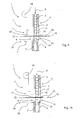
figures 12 - 13 are schematic illustrations of the filling device of the invention during successive steps of the filling method according to the invention for filling capsules with oblong products; -
figure 14 - 15 are schematic illustrations of the filling device of the invention during successive steps of the filling method according to the invention for filling capsules with oblong products, one of which broken and incomplete. - With particular reference to
figures 1 to 7 , there is shown afilling device 1 adapted to fill abottom 3 of a capsule with one ormore products 2. Infigures 1 - 7 there is schematically shown the case in which twoproducts 2 of substantially spherical shape are fed within eachbottom 3. Theproducts 2 may be, for example, tablets, granules, pellets, different types of multiparticulate systems or other solid forms for pharmaceutical, food, and/or cosmetic use. - The
filling device 1 may advantageously be part of an automatic packaging machine of known type, not illustrated, intermittently movable, including groups ofhousings 4 radially arranged on a moving carousel that moves thehousings 4 to cooperate with a plurality of operative stations arranged in succession, among which: a first feeding station for feeding thebottoms 3 to thehousings 4; a second filling station including thefilling device 1 for feeding theproducts 2 to thebottoms 3, in particular one ormore products 2 perbottom 3; a third feeding station for feeding lids to thehousings 4; a forth closing station for closing thebottom 3 with a respective lid to form a capsule filled with one ormore products 2; finally, and a fifth expelling station for expelling the filled capsules from thehousings 4. The automatic packaging machine further includes rejection devices, for rejecting faulty capsules, associated with any one of the stations downstream of the second filling station. - The
filling device 1 includes afeeding conduit 5, adapted to slidingly contain arow 6 ofproducts 2, and a blocking andfeeding system 7, for blocking therow 6 ofproducts 2 and feeding agroup 8 ofproducts 2, including a predefined number ofproducts 2, to abottom 3 of the capsule arranged below. Thegroup 8 ofproducts 2 may comprise one or more products, for example two, three ormore products 2. - The
feeding conduit 5 defines afeeding direction 9 for theproducts 2 and includes abottom end portion 15 that slidingly houses, below therow 6 ofproducts 2, thegroup 8 of alignedproducts 2. - The blocking and
feeding system 7 is of the escapement type and includes a first blocking andfeeding element 10 and a second blocking andfeeding element 11. - The first blocking and
feeding element 10 is positioned below the second blocking andfeeding element 11. - The first blocking and
feeding element 10 is movable, advantageously onto a horizontal plane, between an operative position, wherein it closes thefeeding conduit 5, and an inoperative position, far away from thefeeding conduit 5, wherein thefeeding conduit 5 at thebottom end portion 15 results inferiorly open. - In the embodiment shown in
figures 1-7 , the first blocking andfeeding element 10 includes afirst lamina 12, advantageously flat, arranged below thebottom end portion 15 of thefeeding conduit 5. In operative position, the first blocking andfeeding element 10, in particular thefirst lamina 12, is adapted to support and blocking afirst product 18 of thegroup 8 ofproducts 2 and, therefore, all of theproducts 2 positioned within thefeeding conduit 5 above thefirst product 18. - The second blocking and
feeding element 11 is movable between an operative position, close to thefeeding conduit 5, and an inoperative position, far away from thefeeding conduit 5. Advantageously, in the embodiment illustrated infigures 1-7 , the second blocking andfeeding element 11 includes asecond lamina 13, "L" shaped, adapted to rotate about afulcrum 14 between the operative position and the inoperative position. In particular, thesecond lamina 13 in operative position cooperates with alongitudinal slot 17 achieved in thefeeding conduit 5 to block afurther product 19 of therow 6 ofproducts 2. Once thefurther product 19 has been blocked, therow 6 ofproducts 2 results blocked, i.e. theproducts 2 positioned above thefurther product 19 result blocked. In other words, thesecond lamina 13 do not act onto theproducts 2 of thegroup 8 to be fed that are positioned below therow 6. - The second blocking and
feeding element 11, in particular thesecond lamina 13, is further movable along thefeeding direction 9 in order to be suitably positioned along thefeeding conduit 5, in such a way that a distance between thefirst lamina 12 and thesecond lamina 13 be adjustable. Such distance defines thebottom end portion 15 of thefeeding conduit 5 that houses theproducts 2 of thegroup 8. In other words, by suitably positioning the second blocking and feedingelement 11 along thefeeding conduit 5, the distance between thefirst lamina 12 and thesecond lamina 13 can be varied and, consequently, the predefined number ofproducts 2 of thegroup 8 to be fed to thebelow bottom 3 can be varied. - The
products 2 of thegroup 8 are housed within thebottom end portion 15, aligned from thefirst product 18, lowermost positioned, to alast product 20, uppermost positioned at anupper zone 21 of thebottom end portion 15 of thefeeding conduit 5, immediately below and in contact with thefurther product 19. In case the predefined number of products be one, thefirst product 18 and thelast product 20 coincide. - The
filling device 1 further includes a detectingdevice 16, advantageously a photo detecting device including aphotocell 22 of the barrier type, positioned transversally to thefeeding conduit 5 at theupper zone 21 of thebottom end portion 15 intended to house thelast product 20 of thegroup 8. - The detecting
device 16, in particular thephotocell 22, is therefore adapted to detect whether or not thelast product 20 of thegroup 8 is present within thebottom end portion 15 of thefeeding conduit 5, or, in other words, whether or not thegroup 8 consists of the predefined number ofproducts 2. As theproducts 2 are slidingly housed within thefeeding conduit 5 and, if not retained, are destined to fall by gravity, by verifying whether or not a single product (thelast product 20 of the group 8) is present in theupper zone 21, it can be immediately derived whether or not thegroup 8 ofproducts 2 to be fed to thebelow bottom 3 of the capsule is complete. - Therefore, the
filling device 1 according to the invention detects in an extremely simple, fast and inexpensive, but at the same time extremely reliable, way, not only cases of non-filling, but also partial and incomplete filling (seefigures 9 - 11 ), with no need to weight all of thecapsules 2 downstream of the forth closing station (100% check weight). - The case of non-filling is schematically illustrated in
figure 8 , whereproducts 2 of lenticular shape are shown, one of which is stuck in thefeeding conduit 5 and blocks the entire row ofproducts 2. Cases of non-filling can happen because of other reasons as well, for example because of interruption of the production. - In case the
last product 20 be not present in theupper zone 21 of thebottom end portion 15, the detectingdevice 16 emits a suitable rejection signal to rejection devices for rejecting thebelow bottom 3 only, or the entire capsule formed by thebelow bottom 3. Such rejection devices may advantageously be coupled to, or integral with, thesame filling device 1, or successive operative stations. - The detecting
device 16, in particular thephotocell 22, is advantageously coupled to the second blocking andfeeding element 11, in particular to thesecond lamina 13, and is movable therewith along thefeeding direction 9 in order to be suitably positioned along thefeeding conduit 5, so as to detect the presence of thelast product 20 for any predefined number ofproducts 2 of thegroup 8. In other words, thedetecting device 16, in particular thephotocell 22, is adapted to be positioned immediately below thesecond lamina 13 for a whatsoever distance between the first blocking andfeeding element 10 and the second blocking andfeeding element 11, or, in an equivalent manner, for a whatsoever predefined number ofproducts 2 of thegroup 8. - Alternatively to photo detecting devices with
photocells 22, the detectingdevices 16 may include ultrasound, proximity, or contact sensors adapted to detect the presence of oneproduct 2 in theupper zone 21 of thebottom end portion 15 of thefeeding conduit 5 only, or, in other words, the presence of thelast product 20 of thegroup 8 only. - In embodiments not illustrated, pneumatic systems may be foresee to promote the fall of the
products 2 along thefeeding conduit 5 towards thebottom 3 of the capsule. -
More filling devices 1 of the type illustrated may be arranged side by side and mutually integrated in an automatic packaging machine for filling more capsules simultaneously. - The blocking and
feeding system 7 described before achieves an escapement system. In other words, the first blocking and feedingelement 10 and the second blocking and feedingelement 11 cooperates in proper phase for blocking and releasing therow 6 ofproducts 2 and defining, blocking and releasing thegroup 8 ofproducts 2 to be fed to thebottom 3. - In detail, the filling
device 1 carries out a filling method including the following steps: - a first step (see
fig. 1 ), with the first blocking and feedingelement 10 in operative position and the second blocking and feedingelement 11 in inoperative position, for feeding theproducts 2 downwards within thefeeding conduit 5. The products will results aligned one over the other within thefeeding conduit 5, with afirst product 18 resting on the first blocking and feedingelement 10; - a second step (see
fig. 2 ), with the first blocking and feedingelement 10 in operative position, for moving the second blocking and feedingelement 11 in operative position to block afurther product 19 and to form arow 6 ofproducts 2. In such second step, therefore, agroup 8 ofproducts 2, below therow 6, to be fed to abelow bottom 3 of a capsule housed in ahousing 4, is defined.Such group 8 consists of a predefined number of products 2 (one, two, or more products 2) housed and aligned in abottom end portion 15 of thefeeding conduit 5 defined by a distance between the first blocking and feedingelement 10 and the second blocking and feedingelement 11; - a third step (see
figs. 3 and 4 ), with the second blocking and feeding element in operative position to block thefurther product 19 and thus therow 6 ofproducts 2, for moving the first blocking and feedingelement 10 in inoperative position to inferiorly open thebottom end portion 15 of thefeeding conduit 5 and allow thegroup 6 ofproducts 2 to fall within thebelow bottom 3; - a forth step (see
figs. 5 and 6 ), once the bottom 3 has been filled with the predefined number ofproducts 2 of thegroup 8, for carrying the first blocking and feedingelement 10 in operative position to close thebottom end portion 15 of thefeeding conduit 5, transferring thehousing 4 containing the bottom 3 that has been filled to a successive station, and positioning asuccessive housing 4 with anempty bottom 3 below thefeeding conduit 5; - a fifth step (see
fig. 7 ), with the first blocking and feedingelement 10 in operative position, for moving the second blocking and feedingelement 11 in inoperative position to unblock thefurther product 19 and let theproducts 2 of therow 6 fall towards the first blocking and feedingelement 10 to form asuccessive group 8 ofproducts 2 to be fed to anempty bottom 3 of asuccessive housing 4 according to the steps previously illustrated. - The method further includes, during the second step, a detecting step to detect, by means of a detecting
device 16, advantageously a photo detecting device including aphotocell 22, whether thegroup 6 is complete. - In detail, the method provides for a detecting step to detect, by means of the detecting
means 16, arranged laterally to thefeeding conduit 5, at anupper zone 21 of thebottom end portion 15 of thefeeding conduit 5 intended to house alast product 20 of thegroup 8, whether or not suchlast product 20 is present in suchupper zone 21. Advantageously, the method provides for detecting whether or not just onesingle product 2 is present in theupper zone 21 only, with no need to detect other products in other zones of thebottom end portion 15 of thefeeding conduit 5. - The
group 8 may comprise one ormore products 2, for example two, three, or more products. - If the
group 8 consists of oneproduct 2 only, thefirst product 18 and thelast product 20 coincide and the detectingdevice 16 detects whether theentire group 8 is fed to thebottom 3 of the capsule. - If the
group 8 consists of two ormore products 2, i.e. thefirst product 18 is distinct from thelast product 20, the detectingdevice 16 detects whether or not thegroup 8 is complete. - The method further provides for, in case the detecting
device 16 detects that thegroup 8 is absent or incomplete, sending a rejection signal to rejection devices to reject thebelow bottom 3 only, or the entire capsule formed by thebelow bottom 3, as it contains agroup 8 at least incomplete, even not completely absent, and therefore faulty. Advantageously, the rejection devices may be arranged downstream of thefilling device 1, for example integrated in any one of the successive operative stations. - It has to be noted that, by means of the
filling device 1, there can be checked the correct filling of thebottoms 3 at a very early stage, i.e. during, and not after, the same filling, so allowing for a simpler, more reliable and flexible checking than checking available in the prior art methods. - Thanks to the device and method according to the invention, it is therefore possible to identify and reject, as soon as possible in the automatic packaging machine, the capsules that have not been filled, or that have been incompletely filled, without the need to weight all of the capsules exiting the automatic packaging machine, thus the properly filled capsules as well.
- Notwithstanding that the invention has been illustrated in case the capsules are filled with two products, i.e. in case the
group 8 consists of two products, it is possible to carry out the invention even in case the capsule must be filled with a predefined number ofproducts 2 different from two, i.e. in case thegroup 8 consists of one, three, four, five, ormore products 2. - In case the
group 8 consists of oneproduct 2 only, the second blocking and feedingelement 11, in particular thesecond lamina 13, should be moved and positioned lower than illustrated in case ofgroup 8 consisting of twoproducts 2, at a distance from the first blocking and feedingelement 10, in particular thefirst lamina 12, such as to define abottom end portion 15 of thefeeding conduit 5 adapted to house oneproduct 2 only. - On the contrary, in case the capsule should be filled with three or
more products 2, i.e. in case thegroup 8 consists of more than twoproducts 2, the blocking and feedingelement 11, in particular thesecond lamina 13, should be moved and positioned upper than illustrated in case ofgroup 8 consisting of twoproducts 2, at a distance from the first blocking and feeding element, in particular from thefirst lamina 12, such as to define abottom end portion 15 of thefeeding conduit 5 adapted to house respective three ormore products 2. - Whether the second blocking and feeding
element 11, in particular thesecond lamina 13, be lowered or raised to diminish, or to increase, respectively, the distance from the first blocking and feedingelement 10, in particular thefirst lamina 12, to diminish, or to increase, respectively, the predefined number ofproducts 2 constituting thegroup 8 with respect to the embodiment illustrated in the figures, the detectingdevice 16, in particular thephotocell 22, is moved downwards, or upwards, respectively, along with the second blocking and feedingelement 11 along the feedingdirection 9 to check only theupper zone 21 of thebottom end portion 15 of thefeeding conduit 5 and to detect whether or not thelast product 20 of thegroup 8 is present. - In
figures 12 - 15 there is illustrated thefilling device 1 of the invention for feeding capsules withproducts 2 with oblong shape ingroups 8 of onesingle product 2. In other words, in the embodiments offigures 12 - 15 , thefirst product 18 and thelast product 20 of thegroup 8 coincide. - It is certainly possible to feed
groups 8 of two ormore products 2 with oblong shape tobottoms 3 with suitable dimensions, by suitably adjusting the distance between the first blocking and feedingelement 10 and the second blocking and feedingelement 11 according to what has been described before with reference tofigures 1 - 11 . - Advantageously, in case of
products 2 with oblong shape, it is possible, by means of thefilling device 1 of the invention, to detect capsules filled with broken orincomplete products 2. - Indeed, as can be seen in
figures 14 and15 , in case ofgroups 8 containing broken orincomplete products 2, thefurther product 19 is blocked by the second blocking and feedingelement 11, in particular thesecond lamina 13, in a position such as to be detected by the detectingdevice 16, in particular thephotocell 22, during the third step of the method of the invention, i.e. when the first blocking and feedingelement 10 is in inoperative position to inferiorly open thebottom end portion 15 of thefeeding conduit 5 and the second blocking and feedingelement 11 is in operative position to block thefurther product 19. - The detecting
device 16, once a presence of a product 2 (necessarily the further product 19) has been detected during the third step, sends a rejection signal to reject the bottom 3 (or the entire capsule) that has been just filled, as such capsule contains abroken product 2 and thus is faulty. - On the contrary, if, in the third step of the method, the
products 2 of thegroup 8 were all entire, thefurther product 19 would be blocked in such a position that the detectingdevice 16 would not detect the presence of any products (see for examplefigure 13 ) and consequently would not emit any rejection signal. - It has to be noted that, in case of
products 2 with oblong shape and one ofsuch products 2 of thegroup 8 is broken, the detectingdevice 16 would detect, during the second step, at theupper zone 21, the presence of aproduct 2, that would be thefurther product 19 that projects inferiorly, and not thelast product 20 of thegroup 8. Therefore, the capsule that has been just filled will be rejected, without errors, because during the third phase the detectingdevice 16 would detect the presence of suchfurther product 19.
Claims (10)
- Filling device for filling capsules of bottom (3) - lid type with products (2), advantageously solid forms for pharmaceutical, food, or cosmetic use, including:- a feeding conduit (5) that defines a feeding direction (9) and is adapted to slidingly housing a row (6) of products (2), said feeding conduit (5) including a bottom end portion (15) adapted to slidingly house, below the row (6) of products (2), a group (8) including one or more products (2) aligned;- a blocking and feeding system (7) for blocking the row (6) of products (2) and feeding each bottom (3) below with one group (8) of products (2); said blocking and feeding system (7) including a first blocking and feeding element (10) and a second blocking and feeding element (11); said first blocking and feeding element (10) being movable between an operative position, wherein it closes the feeding conduit (5) and is adapted to support and block a first product (18) of the group (8), and an inoperative position, wherein the feeding conduit (5) at the bottom end portion (15) is inferiorly open; said second blocking and feeding element (11) being movable between an operative position, wherein it is close to the feeding conduit (5) and is adapted to block a further product (19) of the row (6), and an inoperative position, far away from the feeding conduit (5); said second blocking and feeding element (11) being positioned along the feeding direction (9) at a distance from the first blocking and feeding element (10) that defines said bottom end portion (15);- a detecting device (16) adapted to detect, at an upper zone (21) of the bottom end portion (15) of the feeding conduit (5), when the first blocking and feeding element (10) and the second blocking and feeding element (11) are in respective operative positions, whether or not a product (2) is present, and, in case such a product (2) is absent, to send a rejection signal to a rejection device to reject the bottom (3) below, or the capsule formed by the bottom (3) below.
- Filling device according to claim 1, wherein said detecting device (16) is coupled to the second blocking and feeding element (11) and is movable therewith along the feeding direction (9) to be suitably positioned along the feeding conduit (5) at the upper zone (21) of the bottom end portion (15), so as to detect whether a product (2) is present at said upper zone (21) for any predefined number of products (2) of the group (8).
- Filling device according to any one of claims 1 and 2, for filling capsules with products (2) with oblong shape, wherein said detecting device (16) is adapted to detect, at the upper zone (21) of the bottom end portion (15) of the feeding conduit (5), when the first blocking and feeding element (10) is in inoperative position and the second blocking and feeding element (11) is in operative position, whether or not a product (2) is present and, in case such a product (2) is present, to send a rejection signal to a rejection device to reject the bottom (3) below, or the capsule formed by the bottom (3) below.
- Filling device according to claim 1, wherein said detecting device (16) is adapted to detect, at the upper zone (21) of the bottom end portion (15) of the feeding conduit (5) only, whether or not one single product (2) is present.
- Filling device according to any one of claims 1 to 4, wherein said detecting device (16) includes a photodetecting device with a photocell (22) positioned transversely to the feeding conduit (5).
- Filling device according to any one of claims 1 to 5, wherein said group (8) includes two or more products (2).
- Automatic packaging machine for packaging capsules of bottom (3) - lid type, the automatic packaging machine being of intermittent type and including groups of housings (4) radially positioned on a moving carousel that moves the housings (4) to cooperate with a plurality of operative stations arranged in succession, among which:- a first feeding station for feeding the bottoms (3) to the housings (4);- a second filling station for filling the bottoms (3) with the products (2) in number of one or more products (2) per bottom (3);- a third feeding station for feeding lids to the housings (4);- a forth closing station for closing the bottom (3) with a respective lid to form a capsule filled with one or more products (2); and- a fifth discharge station for discharging filled capsules from the housings (4);the automatic packaging machine further including rejecting devices for rejecting faulty capsules and being characterized in that the second filling station includes a filling device (1) according to any one of the preceding claims.
- Filling method for filling bottoms (3) of capsules with a group (8) formed by a predefined number of products (2) by means of a filling device (1) including a feeding conduit (5) adapted to slidingly containing the products (2), a first blocking and feeding element (10) movable between an operative position and an inoperative position, and a second blocking and feeding element (11) movable between an operative position and an inoperative position, including the following step:- a first step, with the first blocking and feeding element (10) in operative position to inferiorly close a bottom end portion (15) of the feeding conduit (5) and the second blocking and feeding element (11) in inoperative position, for feeding the products (2) downwardly within the feeding conduit (5), with a first product (18) resting on the first blocking and feeding element (10);- a second step, with the first blocking and feeding element (10) in operative position, for moving the second blocking and feeding element (11) in operative position to block a further product (19) to form a row (6) of products (2) and to define a group (8) of products (2) to be fed to a bottom (3) below housed in a housing (4), said group (8) being positioned below the row (6) and being formed by a predefined number of products (2) housed and aligned in the bottom end portion (15) of the feeding conduit (5), said bottom end portion (15) being defined by a distance between the first blocking and feeding element (10) and the second blocking and feeding element (11);- a third step, with the second blocking and feeding element (11) in operative position to block the further product (19) and thus the row (6) of products (2), for moving the first blocking and feeding element (10) in inoperative position to inferiorly open the bottom end portion (15) of the feeding conduit (5) and to allow the group (6) of products (2) to fall within the bottom (3) below;- a forth step, once the bottom (3) has been filled with the predefined number of products (2) of the group (8), for moving the first blocking and feeding element in operative position to inferiorly close the bottom end portion (15) of the feeding conduit (5), transferring the housing (4) containing the bottom (3) filled to a subsequent station, and positioning a subsequent housing (4) with an empty bottom (3) below the feeding conduit (5);- a fifth step, with the first blocking and feeding element (10) in operative position, for moving the second blocking and feeding element (11) in inoperative position to unblock the further product (19) and allow the products (2) of the row (6) to fall towards the first blocking and feeding element (10) to form a subsequent group (8) of products (2) to be fed to an empty bottom (3) of a subsequent housing (4);the method further including, during the second step, a detecting step to detect, by means of a detecting device (16), at an upper zone (21) of the bottom end portion (15) of the feeding conduit (5) adapted to house a last product (20) of the group (8), whether or not a product (2) is present and, in case such product (2) is not present in the upper zone (21) of the bottom end portion (15) of the feeding conduit (5), to send a rejection signal to a rejection device to reject the bottom (3) below, or the capsule formed by the bottom (3) below.
- Method according to claim 8, wherein said detecting step provides for detecting, at the upper zone (21) of the bottom end portion (15) of the feeding conduit (5) only, whether or not one single product (2) is present.
- Method according to any one of claims 8 and 9, wherein said products (2) have oblong shape, the method further providing for, during the third step, a further detecting step to detect, by means of the detecting device (16), at the upper zone (21) of the bottom end portion (15) of the feeding conduit (5), whether or not a product (2) is present and, in case such product (2) is present in the upper zone (21) of the bottom end portion (15) of the feeding conduit (5), to send a rejection signal to a rejection device to reject the bottom (3) below, or the capsule formed by the bottom (3) below.
Applications Claiming Priority (2)
| Application Number | Priority Date | Filing Date | Title |
|---|---|---|---|
| IT000500A ITBO20110500A1 (en) | 2011-08-24 | 2011-08-24 | DEVICE AND METHOD TO FILL CAPSULES |
| PCT/EP2012/066262 WO2013026848A1 (en) | 2011-08-24 | 2012-08-21 | Device and method for filling capsules |
Publications (2)
| Publication Number | Publication Date |
|---|---|
| EP2747736A1 EP2747736A1 (en) | 2014-07-02 |
| EP2747736B1 true EP2747736B1 (en) | 2015-04-22 |
Family
ID=44800097
Family Applications (1)
| Application Number | Title | Priority Date | Filing Date |
|---|---|---|---|
| EP20120748495 Active EP2747736B1 (en) | 2011-08-24 | 2012-08-21 | Device and method for filling capsules |
Country Status (3)
| Country | Link |
|---|---|
| EP (1) | EP2747736B1 (en) |
| IT (1) | ITBO20110500A1 (en) |
| WO (1) | WO2013026848A1 (en) |
Families Citing this family (1)
| Publication number | Priority date | Publication date | Assignee | Title |
|---|---|---|---|---|
| ITUB20152455A1 (en) * | 2015-07-24 | 2017-01-24 | Mg 2 Srl | POWER SUPPLY UNIT FOR THE DOSAGE OF AT LEAST TWO PRODUCTS, IN PARTICULAR PHARMACEUTICALS IN GRANULES, IN CAPSULES OR SIMILAR |
Family Cites Families (6)
| Publication number | Priority date | Publication date | Assignee | Title |
|---|---|---|---|---|
| US3774368A (en) * | 1972-06-19 | 1973-11-27 | H Paprzycki | Tablet counting and filling apparatus |
| JP2740566B2 (en) * | 1990-04-26 | 1998-04-15 | 日本エランコ株式会社 | Capsule filling equipment |
| JP2544052B2 (en) * | 1991-12-18 | 1996-10-16 | 日本エランコ株式会社 | Equipment for filling tablets into hard gelatin capsules |
| FR2739232B1 (en) | 1995-09-26 | 1997-10-24 | Thomson Csf | SURFACE ACOUSTIC WAVE FILTER USING THE COUPLING OF THREE ACOUSTIC CHANNELS |
| US7536843B2 (en) * | 2006-01-23 | 2009-05-26 | Astrazeneca Ab | Method and system for dosing a pharmaceutical sample in a packaging machine |
| JP4947271B2 (en) * | 2006-05-16 | 2012-06-06 | クオリカプス株式会社 | Method for filling tablets into capsule body and device for filling tablets into capsules using the filling method |
-
2011
- 2011-08-24 IT IT000500A patent/ITBO20110500A1/en unknown
-
2012
- 2012-08-21 EP EP20120748495 patent/EP2747736B1/en active Active
- 2012-08-21 WO PCT/EP2012/066262 patent/WO2013026848A1/en not_active Ceased
Also Published As
| Publication number | Publication date |
|---|---|
| ITBO20110500A1 (en) | 2013-02-25 |
| WO2013026848A1 (en) | 2013-02-28 |
| EP2747736A1 (en) | 2014-07-02 |
Similar Documents
| Publication | Publication Date | Title |
|---|---|---|
| EP2605969B1 (en) | Filling machine and method for weighing articles | |
| US7392640B2 (en) | Automatic machine for counting and feeding articles, in particular tablets, capsules, pills | |
| US8794273B2 (en) | Intermittent rotating machine for filling capsules with pharmaceutical products | |
| EP2499069B1 (en) | Unscrambling machine for containers and relative process | |
| EP2544977B1 (en) | Bottle feeding system and method | |
| US8464765B2 (en) | Machine for filling bottles with solid forms of pharmaceutical products, in particular capsules, pills, pastilles, and/or tablets | |
| US20170216147A1 (en) | Capsule filling machine | |
| US7735302B2 (en) | Device for picking up articles from a supply station and for inserting the articles into a container | |
| EP3194277B1 (en) | A device and method for feeding pouches to a carousel | |
| US12497240B2 (en) | Method, feeder unit and dispensing system for dispensing discrete medicaments | |
| CN106742375A (en) | For the detection method and device of box packing machine medicine plate induction system | |
| EP2747736A1 (en) | Device and method for filling capsules | |
| WO2006037518A1 (en) | Method for checking capsules | |
| US20100163373A1 (en) | Medicament bottle dispenser | |
| EP2544950B1 (en) | Blister sheet loading apparatus with bounce prevention means | |
| EP4408373B1 (en) | Device and method for feeding capsules | |
| CN212074526U (en) | Vertical cartoning machine of intermittent type formula | |
| CN103359317B (en) | Tablet feeding device | |
| US20060163033A1 (en) | Station for connecting a first line for conveying items with a second line for transferring the items to a packaging machine | |
| CN220350162U (en) | Automatic aluminum-plastic blister packagine machine of medicine | |
| JP2000264301A (en) | Tablet filling method and tablet filling device | |
| WO2025003863A1 (en) | Apparatus and method for weighing and feeding capsules | |
| JPH03111205A (en) | Packer | |
| JP6056910B2 (en) | Tablet extraction device and tablet extraction method |
Legal Events
| Date | Code | Title | Description |
|---|---|---|---|
| PUAI | Public reference made under article 153(3) epc to a published international application that has entered the european phase |
Free format text: ORIGINAL CODE: 0009012 |
|
| 17P | Request for examination filed |
Effective date: 20140324 |
|
| AK | Designated contracting states |
Kind code of ref document: A1 Designated state(s): AL AT BE BG CH CY CZ DE DK EE ES FI FR GB GR HR HU IE IS IT LI LT LU LV MC MK MT NL NO PL PT RO RS SE SI SK SM TR |
|
| DAX | Request for extension of the european patent (deleted) | ||
| GRAP | Despatch of communication of intention to grant a patent |
Free format text: ORIGINAL CODE: EPIDOSNIGR1 |
|
| INTG | Intention to grant announced |
Effective date: 20150211 |
|
| GRAS | Grant fee paid |
Free format text: ORIGINAL CODE: EPIDOSNIGR3 |
|
| GRAA | (expected) grant |
Free format text: ORIGINAL CODE: 0009210 |
|
| AK | Designated contracting states |
Kind code of ref document: B1 Designated state(s): AL AT BE BG CH CY CZ DE DK EE ES FI FR GB GR HR HU IE IS IT LI LT LU LV MC MK MT NL NO PL PT RO RS SE SI SK SM TR |
|
| REG | Reference to a national code |
Ref country code: GB Ref legal event code: FG4D |
|
| REG | Reference to a national code |
Ref country code: CH Ref legal event code: EP |
|
| REG | Reference to a national code |
Ref country code: AT Ref legal event code: REF Ref document number: 722756 Country of ref document: AT Kind code of ref document: T Effective date: 20150515 |
|
| REG | Reference to a national code |
Ref country code: IE Ref legal event code: FG4D |
|
| REG | Reference to a national code |
Ref country code: DE Ref legal event code: R096 Ref document number: 602012006926 Country of ref document: DE Effective date: 20150603 |
|
| REG | Reference to a national code |
Ref country code: CH Ref legal event code: NV Representative=s name: FIAMMENGHI-FIAMMENGHI, CH |
|
| REG | Reference to a national code |
Ref country code: FR Ref legal event code: PLFP Year of fee payment: 4 |
|
| REG | Reference to a national code |
Ref country code: NL Ref legal event code: VDEP Effective date: 20150422 |
|
| REG | Reference to a national code |
Ref country code: AT Ref legal event code: MK05 Ref document number: 722756 Country of ref document: AT Kind code of ref document: T Effective date: 20150422 |
|
| REG | Reference to a national code |
Ref country code: LT Ref legal event code: MG4D |
|
| PG25 | Lapsed in a contracting state [announced via postgrant information from national office to epo] |
Ref country code: NL Free format text: LAPSE BECAUSE OF FAILURE TO SUBMIT A TRANSLATION OF THE DESCRIPTION OR TO PAY THE FEE WITHIN THE PRESCRIBED TIME-LIMIT Effective date: 20150422 |
|
| PG25 | Lapsed in a contracting state [announced via postgrant information from national office to epo] |
Ref country code: NO Free format text: LAPSE BECAUSE OF FAILURE TO SUBMIT A TRANSLATION OF THE DESCRIPTION OR TO PAY THE FEE WITHIN THE PRESCRIBED TIME-LIMIT Effective date: 20150722 Ref country code: FI Free format text: LAPSE BECAUSE OF FAILURE TO SUBMIT A TRANSLATION OF THE DESCRIPTION OR TO PAY THE FEE WITHIN THE PRESCRIBED TIME-LIMIT Effective date: 20150422 Ref country code: ES Free format text: LAPSE BECAUSE OF FAILURE TO SUBMIT A TRANSLATION OF THE DESCRIPTION OR TO PAY THE FEE WITHIN THE PRESCRIBED TIME-LIMIT Effective date: 20150422 Ref country code: PT Free format text: LAPSE BECAUSE OF FAILURE TO SUBMIT A TRANSLATION OF THE DESCRIPTION OR TO PAY THE FEE WITHIN THE PRESCRIBED TIME-LIMIT Effective date: 20150824 Ref country code: HR Free format text: LAPSE BECAUSE OF FAILURE TO SUBMIT A TRANSLATION OF THE DESCRIPTION OR TO PAY THE FEE WITHIN THE PRESCRIBED TIME-LIMIT Effective date: 20150422 Ref country code: LT Free format text: LAPSE BECAUSE OF FAILURE TO SUBMIT A TRANSLATION OF THE DESCRIPTION OR TO PAY THE FEE WITHIN THE PRESCRIBED TIME-LIMIT Effective date: 20150422 |
|
| PGFP | Annual fee paid to national office [announced via postgrant information from national office to epo] |
Ref country code: CH Payment date: 20150721 Year of fee payment: 4 |
|
| PG25 | Lapsed in a contracting state [announced via postgrant information from national office to epo] |
Ref country code: GR Free format text: LAPSE BECAUSE OF FAILURE TO SUBMIT A TRANSLATION OF THE DESCRIPTION OR TO PAY THE FEE WITHIN THE PRESCRIBED TIME-LIMIT Effective date: 20150723 Ref country code: LV Free format text: LAPSE BECAUSE OF FAILURE TO SUBMIT A TRANSLATION OF THE DESCRIPTION OR TO PAY THE FEE WITHIN THE PRESCRIBED TIME-LIMIT Effective date: 20150422 Ref country code: RS Free format text: LAPSE BECAUSE OF FAILURE TO SUBMIT A TRANSLATION OF THE DESCRIPTION OR TO PAY THE FEE WITHIN THE PRESCRIBED TIME-LIMIT Effective date: 20150422 Ref country code: IS Free format text: LAPSE BECAUSE OF FAILURE TO SUBMIT A TRANSLATION OF THE DESCRIPTION OR TO PAY THE FEE WITHIN THE PRESCRIBED TIME-LIMIT Effective date: 20150822 Ref country code: AT Free format text: LAPSE BECAUSE OF FAILURE TO SUBMIT A TRANSLATION OF THE DESCRIPTION OR TO PAY THE FEE WITHIN THE PRESCRIBED TIME-LIMIT Effective date: 20150422 |
|
| PGFP | Annual fee paid to national office [announced via postgrant information from national office to epo] |
Ref country code: BE Payment date: 20150722 Year of fee payment: 4 Ref country code: FR Payment date: 20150727 Year of fee payment: 4 |
|
| REG | Reference to a national code |
Ref country code: DE Ref legal event code: R097 Ref document number: 602012006926 Country of ref document: DE |
|
| PG25 | Lapsed in a contracting state [announced via postgrant information from national office to epo] |
Ref country code: EE Free format text: LAPSE BECAUSE OF FAILURE TO SUBMIT A TRANSLATION OF THE DESCRIPTION OR TO PAY THE FEE WITHIN THE PRESCRIBED TIME-LIMIT Effective date: 20150422 Ref country code: DK Free format text: LAPSE BECAUSE OF FAILURE TO SUBMIT A TRANSLATION OF THE DESCRIPTION OR TO PAY THE FEE WITHIN THE PRESCRIBED TIME-LIMIT Effective date: 20150422 |
|
| PLBE | No opposition filed within time limit |
Free format text: ORIGINAL CODE: 0009261 |
|
| STAA | Information on the status of an ep patent application or granted ep patent |
Free format text: STATUS: NO OPPOSITION FILED WITHIN TIME LIMIT |
|
| PG25 | Lapsed in a contracting state [announced via postgrant information from national office to epo] |
Ref country code: PL Free format text: LAPSE BECAUSE OF FAILURE TO SUBMIT A TRANSLATION OF THE DESCRIPTION OR TO PAY THE FEE WITHIN THE PRESCRIBED TIME-LIMIT Effective date: 20150422 Ref country code: RO Free format text: LAPSE BECAUSE OF NON-PAYMENT OF DUE FEES Effective date: 20150422 Ref country code: SK Free format text: LAPSE BECAUSE OF FAILURE TO SUBMIT A TRANSLATION OF THE DESCRIPTION OR TO PAY THE FEE WITHIN THE PRESCRIBED TIME-LIMIT Effective date: 20150422 Ref country code: CZ Free format text: LAPSE BECAUSE OF FAILURE TO SUBMIT A TRANSLATION OF THE DESCRIPTION OR TO PAY THE FEE WITHIN THE PRESCRIBED TIME-LIMIT Effective date: 20150422 |
|
| 26N | No opposition filed |
Effective date: 20160125 |
|
| PG25 | Lapsed in a contracting state [announced via postgrant information from national office to epo] |
Ref country code: MC Free format text: LAPSE BECAUSE OF FAILURE TO SUBMIT A TRANSLATION OF THE DESCRIPTION OR TO PAY THE FEE WITHIN THE PRESCRIBED TIME-LIMIT Effective date: 20150422 Ref country code: LU Free format text: LAPSE BECAUSE OF FAILURE TO SUBMIT A TRANSLATION OF THE DESCRIPTION OR TO PAY THE FEE WITHIN THE PRESCRIBED TIME-LIMIT Effective date: 20150821 |
|
| PG25 | Lapsed in a contracting state [announced via postgrant information from national office to epo] |
Ref country code: SI Free format text: LAPSE BECAUSE OF FAILURE TO SUBMIT A TRANSLATION OF THE DESCRIPTION OR TO PAY THE FEE WITHIN THE PRESCRIBED TIME-LIMIT Effective date: 20150422 |
|
| REG | Reference to a national code |
Ref country code: IE Ref legal event code: MM4A |
|
| PG25 | Lapsed in a contracting state [announced via postgrant information from national office to epo] |
Ref country code: IE Free format text: LAPSE BECAUSE OF NON-PAYMENT OF DUE FEES Effective date: 20150821 |
|
| PG25 | Lapsed in a contracting state [announced via postgrant information from national office to epo] |
Ref country code: BE Free format text: LAPSE BECAUSE OF NON-PAYMENT OF DUE FEES Effective date: 20160831 |
|
| PG25 | Lapsed in a contracting state [announced via postgrant information from national office to epo] |
Ref country code: MT Free format text: LAPSE BECAUSE OF FAILURE TO SUBMIT A TRANSLATION OF THE DESCRIPTION OR TO PAY THE FEE WITHIN THE PRESCRIBED TIME-LIMIT Effective date: 20150422 |
|
| REG | Reference to a national code |
Ref country code: CH Ref legal event code: PL |
|
| GBPC | Gb: european patent ceased through non-payment of renewal fee |
Effective date: 20160821 |
|
| PG25 | Lapsed in a contracting state [announced via postgrant information from national office to epo] |
Ref country code: CH Free format text: LAPSE BECAUSE OF NON-PAYMENT OF DUE FEES Effective date: 20160831 Ref country code: LI Free format text: LAPSE BECAUSE OF NON-PAYMENT OF DUE FEES Effective date: 20160831 |
|
| REG | Reference to a national code |
Ref country code: FR Ref legal event code: ST Effective date: 20170428 |
|
| PG25 | Lapsed in a contracting state [announced via postgrant information from national office to epo] |
Ref country code: BG Free format text: LAPSE BECAUSE OF FAILURE TO SUBMIT A TRANSLATION OF THE DESCRIPTION OR TO PAY THE FEE WITHIN THE PRESCRIBED TIME-LIMIT Effective date: 20150422 Ref country code: HU Free format text: LAPSE BECAUSE OF FAILURE TO SUBMIT A TRANSLATION OF THE DESCRIPTION OR TO PAY THE FEE WITHIN THE PRESCRIBED TIME-LIMIT; INVALID AB INITIO Effective date: 20120821 Ref country code: SM Free format text: LAPSE BECAUSE OF FAILURE TO SUBMIT A TRANSLATION OF THE DESCRIPTION OR TO PAY THE FEE WITHIN THE PRESCRIBED TIME-LIMIT Effective date: 20150422 |
|
| PG25 | Lapsed in a contracting state [announced via postgrant information from national office to epo] |
Ref country code: SE Free format text: LAPSE BECAUSE OF FAILURE TO SUBMIT A TRANSLATION OF THE DESCRIPTION OR TO PAY THE FEE WITHIN THE PRESCRIBED TIME-LIMIT Effective date: 20150422 Ref country code: CY Free format text: LAPSE BECAUSE OF FAILURE TO SUBMIT A TRANSLATION OF THE DESCRIPTION OR TO PAY THE FEE WITHIN THE PRESCRIBED TIME-LIMIT Effective date: 20150422 |
|
| PG25 | Lapsed in a contracting state [announced via postgrant information from national office to epo] |
Ref country code: FR Free format text: LAPSE BECAUSE OF NON-PAYMENT OF DUE FEES Effective date: 20160831 Ref country code: GB Free format text: LAPSE BECAUSE OF NON-PAYMENT OF DUE FEES Effective date: 20160821 |
|
| PG25 | Lapsed in a contracting state [announced via postgrant information from national office to epo] |
Ref country code: TR Free format text: LAPSE BECAUSE OF FAILURE TO SUBMIT A TRANSLATION OF THE DESCRIPTION OR TO PAY THE FEE WITHIN THE PRESCRIBED TIME-LIMIT Effective date: 20150422 Ref country code: MK Free format text: LAPSE BECAUSE OF FAILURE TO SUBMIT A TRANSLATION OF THE DESCRIPTION OR TO PAY THE FEE WITHIN THE PRESCRIBED TIME-LIMIT Effective date: 20150422 |
|
| PG25 | Lapsed in a contracting state [announced via postgrant information from national office to epo] |
Ref country code: AL Free format text: LAPSE BECAUSE OF FAILURE TO SUBMIT A TRANSLATION OF THE DESCRIPTION OR TO PAY THE FEE WITHIN THE PRESCRIBED TIME-LIMIT Effective date: 20150422 |
|
| REG | Reference to a national code |
Ref country code: DE Ref legal event code: R082 Ref document number: 602012006926 Country of ref document: DE Representative=s name: KILBURN & STRODE LLP, NL |
|
| P01 | Opt-out of the competence of the unified patent court (upc) registered |
Effective date: 20230509 |
|
| PGFP | Annual fee paid to national office [announced via postgrant information from national office to epo] |
Ref country code: DE Payment date: 20250827 Year of fee payment: 14 |
|
| PGFP | Annual fee paid to national office [announced via postgrant information from national office to epo] |
Ref country code: IT Payment date: 20250827 Year of fee payment: 14 |