EP2747453A1 - Battery door and hearing device - Google Patents
Battery door and hearing device Download PDFInfo
- Publication number
- EP2747453A1 EP2747453A1 EP12199096.4A EP12199096A EP2747453A1 EP 2747453 A1 EP2747453 A1 EP 2747453A1 EP 12199096 A EP12199096 A EP 12199096A EP 2747453 A1 EP2747453 A1 EP 2747453A1
- Authority
- EP
- European Patent Office
- Prior art keywords
- battery
- axis
- battery door
- locking element
- bottom part
- Prior art date
- Legal status (The legal status is an assumption and is not a legal conclusion. Google has not performed a legal analysis and makes no representation as to the accuracy of the status listed.)
- Ceased
Links
Images


Classifications
-
- H—ELECTRICITY
- H04—ELECTRIC COMMUNICATION TECHNIQUE
- H04R—LOUDSPEAKERS, MICROPHONES, GRAMOPHONE PICK-UPS OR LIKE ACOUSTIC ELECTROMECHANICAL TRANSDUCERS; ELECTRIC HEARING AIDS; PUBLIC ADDRESS SYSTEMS
- H04R25/00—Electric hearing aids
- H04R25/60—Mounting or interconnection of hearing aid parts, e.g. inside tips, housings or to ossicles
- H04R25/602—Mounting or interconnection of hearing aid parts, e.g. inside tips, housings or to ossicles of batteries
Definitions
- the present invention relates to a battery door for a hearing device and a hearing device comprising a battery door.
- a focus in the hearing aid industry is to make hearing aids smaller and more discrete for the benefit of the user and thus a design which can decrease the size of the hearing aid is of importance. Further, it is of great interest from a cost perspective that designs are easy and cheap to manufacture.
- a button battery is used in a hearing device and traditionally a battery door of a hearing aid has been fitted with a locking mechanism, e.g. operated by a small slider or relying on a spring effect of the material, leading to bulky hearing devices a complex manufacturing process and/or high failure rate of the locking mechanism.
- a battery door for a hearing device comprising a body with at least one pivoting element for coupling the battery door to a hearing device housing such that the battery door is configured to pivot about a pivoting axis.
- the body has a bottom part and a sidewall.
- the bottom part has a first bottom surface and the sidewall has a first wall surface, the first wall surface comprising contact points for supporting a battery with a battery radius, wherein the first bottom surface and the first wall surface at least partly defines a battery compartment with a battery axis and contact points of the first wall surface arranged at a battery distance from the battery axis.
- a center axis perpendicularly crosses the pivoting axis and crosses the battery axis.
- the battery door further comprises a first locking element and a second locking element.
- the first locking element may be arranged in the bottom part of the body and/or the second locking element may be arranged in the bottom part of the body.
- a hearing device comprising a housing and a battery door as described is disclosed, wherein the hearing device comprises at least one engagement member configured to engage with the first and second locking element of the battery door, when the battery door is in a first and second position, respectively.
- the disclosed battery door is advantageous in that it decreases the space needed for the locking mechanism, thus facilitating a small hearing device and a small battery door. Furthermore, due to a simplification of the locking mechanism, a battery door that is simple to manufacture and has reduced requirements to material quality is provided, resulting in reduced costs and reduced failure rates.
- a positive angle between the center axis and an axis is an angle from the center axis to the respective axis in the intended closing direction of the battery door.
- a negative angle between the center axis and an axis is an angle from the center axis to the respective axis in the intended opening direction of the battery door.
- the battery distance is measured perpendicular to the battery axis.
- the body has a first end and a second end.
- the battery is inserted into the battery compartment through an opening in the first end along the battery axis.
- the bottom part of the body is the part of the body between the first bottom surface and the second end.
- the first locking element may be arranged in the bottom part at a first distance from the battery axis.
- the first distance may be less than the battery distance.
- the second locking element may be arranged in the bottom part at a second distance from the battery axis.
- the second distance may be less than the battery distance.
- the first distance and the second distance are both less than battery distance.
- the second distance may be less than the first distance.
- the second distance may be larger than the first distance.
- the first locking element may be arranged on a first straight axis perpendicularly crossing the pivoting axis, wherein a first angle between the center axis and the first axis may be in the range from -20° to 20°.
- the first angle may be in the range from -10° to 10°.
- the first angle may be larger than 0°.
- the second locking element may be arranged on a second straight axis perpendicularly crossing the pivoting axis, wherein a second angle between the center axis and the second axis may be in the range from -20° to 20°.
- the second angle may be in the range from -10° to 10°.
- the second angle may be less than 0°.
- the smallest angle between the first axis and the second axis is denoted the third angle.
- the numerical value of the third angle may be in the range from 5° to 30°, e.g. in the range from 5° to 20°. In an exemplary battery door, the numerical value of the third angle is in the range from 6° to 15°, e.g. 8°.
- the third angle must be large enough to facilitate a tactile difference between the first and second positions. On the other hand, a small angle may be desired to facilitate a compact design and prevent the battery door from being too open in a first position.
- the locking elements may comprise one or more recesses in the bottom surface.
- a recess may extend in any direction and may be in one direction in the first locking element and another in the second locking element.
- the locking element(s) may each comprise one or more recesses extending radially inward towards the battery axis. Thereby a compact design is facilitated preventing the locking mechanism from taking up excess space.
- the bottom part may have a first cutout section.
- the first cutout section may extend to a second wall surface or outer surface of the sidewall, such that an electrical connector placed inside the housing of the hearing aid engages with the bottom of a battery placed in the battery door when a user closes the battery door by pivoting the battery door in the closing direction.
- the bottom part may also have a second cutout section.
- the second cutout may be located such that the bottom part comprises an arc-shaped bridge element.
- the first locking element and/or the second locking element may be formed on an outer edge of the bridge element.
- the thickness of the bridge element is to be determined by the specific material in use and should be thin enough to provide enough flexibility for an engagement member of the hearing aid to engage with the locking elements and thick enough to prevent the bridge element from breaking due to wear and tear.
- the second cutout section may be an open cutout forming at least a first arm element in the bottom part.
- the first arm element may point in the opening or the closing direction.
- the second cutout may form a second arm element in the bottom part.
- the first locking element and the second locking element may be formed in the first arm element.
- the first locking element is formed in the first arm element and the second locking element is formed in the second arm element.
- An arm element facilitates greater flexibility, but also dictates a higher demand to strength of the material.
- one of the locking elements e.g. the first locking element, may be located on the first arm element while the other locking element, e.g. the second locking element, is formed as part of a cutout.
- Fig. 1 shows a top view of an exemplary battery door 10 for a hearing device.
- the battery door 10 comprises a body 12 with at least one pivoting element 14 for coupling the battery door 10 to the hearing device such that the battery door 10 is configured to pivot about a pivoting axis 32.
- the body may comprise first and second pivoting elements with bores for accomodating a rod or pin to pivot the body 12 about the rod/pin forming the pivoting axis 32.
- the body 12 has a bottom part 16 and a sidewall 18, the bottom part 16 having a first bottom surface 20 and the sidewall having a first wall surface 22 and a second wall surface 24.
- the first wall surface comprises contact points and/or contact surfaces (26) for supporting a battery 28 with a battery radius R bat (see Fig.
- the first bottom surface 20 and the first wall surface 22 at least partly defines a battery compartment 30 with a battery axis 34 and contact points of the first wall surface 22 arranged at a battery distance R 1 (see Fig. 3 ) from the battery axis 34.
- the battery door 10 comprises a first locking element 38 formed as a first recess extending radially inward (perpendicular to the battery axis) in the bottom part 16.
- the battery door 10 comprises a second locking element 42 formed as a second recess extending radially inward (perpendicular to the battery axis) in the bottom part 16.
- the bottom part 16 has a first cutout 50 extending to the second wall surface 24, such that an electrical connector arranged inside the housing of the hearing aid is connectable to a bottom of a battery placed in the battery door by pivoting the battery door about the pivot axis 32.
- the battery bottom of a battery is the battery surface facing the bottom part.
- the bottom part 16 has a second cutout 52 forming a bridge element 53 in the bottom part, and wherein the first locking element 38 and the second locking element 42 are formed on an outer edge of the bridge element.
- the bridge element 53 is flexible and allows the bridge element 53 with the first and second locking elements to move during opening and closing of the battery door, such that the first and second locking elements can engage with engagement member(s) of a hearing device housing in first and second positions, respectively.
- the user opens the battery door 10 by pushing the tip of the handle element 54 in the opening direction 48. Closing the battery door is achieved by pushing the body 12 or the handle element 54 in the closing direction 46.
- Fig. 2 shows a top view of the battery door 10 with indication of the center axis, first axis and second axis.
- a center axis 36 perpendicularly crosses the pivoting axis 32 and crosses the battery axis 34.
- a first axis 40 perpendicularly crosses the pivoting axis 32 and crosses the first locking element 38.
- a second axis 44 perpendicularly crosses the pivoting axis 32 and crosses the second locking element 42.
- the angle between the center axis 42 and the first axis 40 and the angle between the center axis 42 and the second axis 44, are denoted as V 1 and V 2 respectively.
- a positive angle between the center axis 42 and an axis is an angle from the center axis 42 to the respective axis in the intended closing direction 46 of the battery door 10.
- a negative angle between the center axis 42 and an axis is an angle from the center axis 42 to the respective axis in the intended opening direction 48 of the battery door 10.
- V 12 is the third angle between the second axis and the first axis. In the example shown, V 1 is 2°, V 2 is -6° and V 12 is therefore 8°, thus providing a good balance between compact design and tactile impression between the first position and the second position.
- Fig. 3 shows a top view of an exemplary battery door 10 with indication of distances.
- a first distance from the battery axis 34 to the bottom of the recess forming the first locking element 38 is denoted R lock1
- a second distance from the battery axis 34 to the bottom of the recess forming the second locking element 42 is denoted R lock2 .
- Fig. 4 shows a perspective view of the battery door 10 with a battery 28 having a battery radius R bat inserted in the battery compartment 30.
- the at least one pivoting element of the battery door 10 comprises first pivoting element 14a and second pivoting element 14b each having an opening for a pivot pin.
- the at least one pivoting element may be constructed as a single pivoting element or a plurality of pivoting elements.
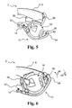
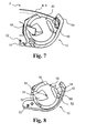
- Figs. 5-7 show an exemplary hearing device 2 comprising an exemplary battery door 10 in an open position, first position (OFF) and second position (ON), respectively.
- the battery door 10 When the battery door 10 is rotated around the pivoting axis 32 in the closing direction 46, the battery door 10 will engage in the first position, as shown in Fig. 6 , where an engagement member 56 of the housing 4, engages the first locking element 38.
- the battery door 10 When a user rotates the battery door further in the closing direction 46, the battery door 10 will engage in the second position as shown in Fig. 7 , where the engagement member 56 engages the second locking element 42.
- the first and second positions may be utilized as means for switching the hearing device off and on, thus having a first position where the hearing device is off and the battery door is nearly closed, thereby supporting and storing the battery and protecting the battery door from mechanical stress.
- an electrical connector 58 of the hearing device 2 will connect to the bottom part of a battery placed in the battery compartment through the first cutout.
- the battery bottom of a battery is the battery surface facing the bottom part of the battery door when the battery is inserted in the battery compartment..
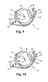
- Fig. 8 shows an exemplary battery door, where the second cutout 52 is an open cutout, forming a first arm element 60 of the bottom part 16 pointing in the closing direction, wherein the first locking element 38 and the second locking element 42 are located.
- the first arm element flexes radially during opening and closing as indicated.
- Fig. 9 shows an exemplary battery door, where the second cutout 52 is an open cutout, forming a first arm element 60 of the bottom part 16 pointing in the opening direction, wherein the first locking element 38 is located, and the opening of the second cutout 52 forms the second locking element 42.
- Fig. 10 shows an exemplary battery door according to the invention, where the second cutout 52 is an open cutout, and where the opening of the second cutout 52 is located between the first locking element 38 and the second locking element 42 forming a first arm element 60 and a second arm element 62 of the bottom part 16, wherein the first locking element 38 and the second locking element 42 are located on different arm elements.
Landscapes
- Health & Medical Sciences (AREA)
- General Health & Medical Sciences (AREA)
- Neurosurgery (AREA)
- Otolaryngology (AREA)
- Physics & Mathematics (AREA)
- Engineering & Computer Science (AREA)
- Acoustics & Sound (AREA)
- Signal Processing (AREA)
- Battery Mounting, Suspending (AREA)
Abstract
Description
- The present invention relates to a battery door for a hearing device and a hearing device comprising a battery door.
- A focus in the hearing aid industry is to make hearing aids smaller and more discrete for the benefit of the user and thus a design which can decrease the size of the hearing aid is of importance. Further, it is of great interest from a cost perspective that designs are easy and cheap to manufacture. Generally a button battery is used in a hearing device and traditionally a battery door of a hearing aid has been fitted with a locking mechanism, e.g. operated by a small slider or relying on a spring effect of the material, leading to bulky hearing devices a complex manufacturing process and/or high failure rate of the locking mechanism.
- Despite the known solutions, there is still a need for reducing the size of a hearing device and components or parts thereof.
- Accordingly, a battery door for a hearing device is provided, the battery door comprising a body with at least one pivoting element for coupling the battery door to a hearing device housing such that the battery door is configured to pivot about a pivoting axis. The body has a bottom part and a sidewall. The bottom part has a first bottom surface and the sidewall has a first wall surface, the first wall surface comprising contact points for supporting a battery with a battery radius, wherein the first bottom surface and the first wall surface at least partly defines a battery compartment with a battery axis and contact points of the first wall surface arranged at a battery distance from the battery axis. A center axis perpendicularly crosses the pivoting axis and crosses the battery axis. The battery door further comprises a first locking element and a second locking element. The first locking element may be arranged in the bottom part of the body and/or the second locking element may be arranged in the bottom part of the body.
- A hearing device comprising a housing and a battery door as described is disclosed, wherein the hearing device comprises at least one engagement member configured to engage with the first and second locking element of the battery door, when the battery door is in a first and second position, respectively.
- The disclosed battery door is advantageous in that it decreases the space needed for the locking mechanism, thus facilitating a small hearing device and a small battery door. Furthermore, due to a simplification of the locking mechanism, a battery door that is simple to manufacture and has reduced requirements to material quality is provided, resulting in reduced costs and reduced failure rates.
- The above and other features and advantages of the present invention will become readily apparent to those skilled in the art by the following detailed description of exemplary embodiments thereof with reference to the attached drawings, in which:
- Fig. 1
- schematically illustrates an exemplary battery door according to the invention,
- Fig. 2
- schematically illustrates an exemplary battery door according to the invention with important angles,
- Fig. 3
- schematically illustrates an exemplary battery door according to the invention with important distances,
- Fig. 4
- illustrates a perspective view of an exemplary battery door with a battery,
- Fig. 5
- schematically illustrates an exemplary hearing device according to the invention, with the battery door in an open position,
- Fig. 6
- schematically illustrates an exemplary hearing device according to the invention, with the battery door in a first position,
- Fig. 7
- schematically illustrates an exemplary hearing device according to the invention, with the battery door in a second position,
- Fig. 8
- schematically illustrates an exemplary battery door according to the invention,
- Fig. 9
- schematically illustrates an exemplary battery door according to the invention, and
- Fig. 10
- schematically illustrates an exemplary battery door according to the invention.
- The figures are schematic and simplified for clarity, and they merely show details which are essential to the understanding of the invention, while other details have been left out. Throughout, the same reference numerals are used for identical or corresponding parts.
- A positive angle between the center axis and an axis is an angle from the center axis to the respective axis in the intended closing direction of the battery door.
- A negative angle between the center axis and an axis is an angle from the center axis to the respective axis in the intended opening direction of the battery door.
- The battery distance is measured perpendicular to the battery axis.
- The body has a first end and a second end. Typically, the battery is inserted into the battery compartment through an opening in the first end along the battery axis.
- The bottom part of the body is the part of the body between the first bottom surface and the second end.
- The first locking element may be arranged in the bottom part at a first distance from the battery axis. The first distance may be less than the battery distance. The second locking element may be arranged in the bottom part at a second distance from the battery axis. The second distance may be less than the battery distance. In a prefered battery door, the first distance and the second distance are both less than battery distance. As a consequence the locking mechanism of the battery door is an integrated part of the bottom part, located underneath the battery when inserted, facilitating a battery door with reduced size. The second distance may be less than the first distance. The second distance may be larger than the first distance.
- The first locking element may be arranged on a first straight axis perpendicularly crossing the pivoting axis, wherein a first angle between the center axis and the first axis may be in the range from -20° to 20°. The first angle may be in the range from -10° to 10°. The first angle may be larger than 0°.
- The second locking element may be arranged on a second straight axis perpendicularly crossing the pivoting axis, wherein a second angle between the center axis and the second axis may be in the range from -20° to 20°. The second angle may be in the range from -10° to 10°. The second angle may be less than 0°.
- The smallest angle between the first axis and the second axis is denoted the third angle. The numerical value of the third angle may be in the range from 5° to 30°, e.g. in the range from 5° to 20°. In an exemplary battery door, the numerical value of the third angle is in the range from 6° to 15°, e.g. 8°. The third angle must be large enough to facilitate a tactile difference between the first and second positions. On the other hand, a small angle may be desired to facilitate a compact design and prevent the battery door from being too open in a first position.
- The locking elements may comprise one or more recesses in the bottom surface. A recess may extend in any direction and may be in one direction in the first locking element and another in the second locking element. The locking element(s) may each comprise one or more recesses extending radially inward towards the battery axis. Thereby a compact design is facilitated preventing the locking mechanism from taking up excess space.
- The bottom part may have a first cutout section. The first cutout section may extend to a second wall surface or outer surface of the sidewall, such that an electrical connector placed inside the housing of the hearing aid engages with the bottom of a battery placed in the battery door when a user closes the battery door by pivoting the battery door in the closing direction.
- To provide a certain amount of flexibility to the locking elements, the bottom part may also have a second cutout section. The second cutout may be located such that the bottom part comprises an arc-shaped bridge element. The first locking element and/or the second locking element may be formed on an outer edge of the bridge element. The thickness of the bridge element is to be determined by the specific material in use and should be thin enough to provide enough flexibility for an engagement member of the hearing aid to engage with the locking elements and thick enough to prevent the bridge element from breaking due to wear and tear.
- The second cutout section may be an open cutout forming at least a first arm element in the bottom part. The first arm element may point in the opening or the closing direction. The second cutout may form a second arm element in the bottom part. The first locking element and the second locking element may be formed in the first arm element. In an exemplary battery door, the first locking element is formed in the first arm element and the second locking element is formed in the second arm element. An arm element facilitates greater flexibility, but also dictates a higher demand to strength of the material. In an exemplary battery door, one of the locking elements, e.g. the first locking element, may be located on the first arm element while the other locking element, e.g. the second locking element, is formed as part of a cutout.
-
Fig. 1 shows a top view of anexemplary battery door 10 for a hearing device. Thebattery door 10 comprises abody 12 with at least one pivotingelement 14 for coupling thebattery door 10 to the hearing device such that thebattery door 10 is configured to pivot about a pivotingaxis 32. The body may comprise first and second pivoting elements with bores for accomodating a rod or pin to pivot thebody 12 about the rod/pin forming the pivotingaxis 32. Thebody 12 has abottom part 16 and asidewall 18, thebottom part 16 having afirst bottom surface 20 and the sidewall having a first wall surface 22 and asecond wall surface 24. The first wall surface comprises contact points and/or contact surfaces (26) for supporting abattery 28 with a battery radius Rbat (seeFig. 4 ) Thefirst bottom surface 20 and the first wall surface 22 at least partly defines abattery compartment 30 with abattery axis 34 and contact points of the first wall surface 22 arranged at a battery distance R1 (seeFig. 3 ) from thebattery axis 34. Further, thebattery door 10 comprises afirst locking element 38 formed as a first recess extending radially inward (perpendicular to the battery axis) in thebottom part 16. Further, thebattery door 10 comprises asecond locking element 42 formed as a second recess extending radially inward (perpendicular to the battery axis) in thebottom part 16. - The
bottom part 16 has afirst cutout 50 extending to thesecond wall surface 24, such that an electrical connector arranged inside the housing of the hearing aid is connectable to a bottom of a battery placed in the battery door by pivoting the battery door about thepivot axis 32. The battery bottom of a battery is the battery surface facing the bottom part. Thebottom part 16 has asecond cutout 52 forming abridge element 53 in the bottom part, and wherein thefirst locking element 38 and thesecond locking element 42 are formed on an outer edge of the bridge element. Thebridge element 53 is flexible and allows thebridge element 53 with the first and second locking elements to move during opening and closing of the battery door, such that the first and second locking elements can engage with engagement member(s) of a hearing device housing in first and second positions, respectively. The user opens thebattery door 10 by pushing the tip of thehandle element 54 in theopening direction 48. Closing the battery door is achieved by pushing thebody 12 or thehandle element 54 in the closingdirection 46. -
Fig. 2 shows a top view of thebattery door 10 with indication of the center axis, first axis and second axis. Acenter axis 36 perpendicularly crosses the pivotingaxis 32 and crosses thebattery axis 34. Afirst axis 40 perpendicularly crosses the pivotingaxis 32 and crosses thefirst locking element 38. Asecond axis 44 perpendicularly crosses the pivotingaxis 32 and crosses thesecond locking element 42. The angle between thecenter axis 42 and thefirst axis 40 and the angle between thecenter axis 42 and thesecond axis 44, are denoted as V1 and V2 respectively. A positive angle between thecenter axis 42 and an axis is an angle from thecenter axis 42 to the respective axis in the intended closingdirection 46 of thebattery door 10. A negative angle between thecenter axis 42 and an axis is an angle from thecenter axis 42 to the respective axis in the intendedopening direction 48 of thebattery door 10. Also shown is the third angle between the second axis and the first axis, denoted V12. In the example shown, V1 is 2°, V2 is -6° and V12 is therefore 8°, thus providing a good balance between compact design and tactile impression between the first position and the second position. -
Fig. 3 shows a top view of anexemplary battery door 10 with indication of distances. A first distance from thebattery axis 34 to the bottom of the recess forming thefirst locking element 38 is denoted Rlock1, and a second distance from thebattery axis 34 to the bottom of the recess forming thesecond locking element 42 is denoted Rlock2. -
Fig. 4 shows a perspective view of thebattery door 10 with abattery 28 having a battery radius Rbat inserted in thebattery compartment 30. The at least one pivoting element of thebattery door 10 comprises first pivotingelement 14a andsecond pivoting element 14b each having an opening for a pivot pin. The at least one pivoting element may be constructed as a single pivoting element or a plurality of pivoting elements. -
Figs. 5-7 show anexemplary hearing device 2 comprising anexemplary battery door 10 in an open position, first position (OFF) and second position (ON), respectively. When thebattery door 10 is rotated around the pivotingaxis 32 in the closingdirection 46, thebattery door 10 will engage in the first position, as shown inFig. 6 , where anengagement member 56 of the housing 4, engages thefirst locking element 38. When a user rotates the battery door further in the closingdirection 46, thebattery door 10 will engage in the second position as shown inFig. 7 , where theengagement member 56 engages thesecond locking element 42. The first and second positions may be utilized as means for switching the hearing device off and on, thus having a first position where the hearing device is off and the battery door is nearly closed, thereby supporting and storing the battery and protecting the battery door from mechanical stress. When thebattery door 10 is in the second position, anelectrical connector 58 of thehearing device 2 will connect to the bottom part of a battery placed in the battery compartment through the first cutout. The battery bottom of a battery is the battery surface facing the bottom part of the battery door when the battery is inserted in the battery compartment.. -
Fig. 8 shows an exemplary battery door, where thesecond cutout 52 is an open cutout, forming afirst arm element 60 of thebottom part 16 pointing in the closing direction, wherein thefirst locking element 38 and thesecond locking element 42 are located. The first arm element flexes radially during opening and closing as indicated. -
Fig. 9 shows an exemplary battery door, where thesecond cutout 52 is an open cutout, forming afirst arm element 60 of thebottom part 16 pointing in the opening direction, wherein thefirst locking element 38 is located, and the opening of thesecond cutout 52 forms thesecond locking element 42. -
Fig. 10 shows an exemplary battery door according to the invention, where thesecond cutout 52 is an open cutout, and where the opening of thesecond cutout 52 is located between thefirst locking element 38 and thesecond locking element 42 forming afirst arm element 60 and asecond arm element 62 of thebottom part 16, wherein thefirst locking element 38 and thesecond locking element 42 are located on different arm elements. -
- 2
- hearing device
- 4
- housing
- 6
- first housing part
- 10
- battery door
- 12
- body
- 14, 14a, 14b
- pivoting element
- 16
- bottom part
- 18
- sidewall
- 20
- first bottom surface
- 22
- first wall surface
- 24
- second wall surface
- 26
- contact points
- 28
- battery
- 30
- battery compartment
- 32
- pivoting axis
- 34
- battery axis
- 36
- center axis
- 38
- first locking element
- 40
- first axis
- 42
- second locking element
- 44
- second axis
- 46
- closing direction
- 48
- opening direction
- 50
- first cutout
- 52
- second cutout
- 53
- bridge element
- 54
- handle element
- 56
- engagement member
- 58
- electrical connector
- 60
- first arm element
- 62
- second arm element
- Rbat
- battery radius
- R1
- battery distance
- Rlock1
- first distance from battery axis to first locking element
- Rlock2
- second distance from battery axis to second locking element
- V1
- first angle from the center axis to the first axis
- V2
- second angle from the second axis to the center axis
- V12
- third angle being the smallest angle between the second axis and the first axis.
Claims (15)
- A battery door for a hearing device, the battery door comprising a body with at least one pivoting element for coupling the battery door to a hearing device housing such that the battery door is configured to pivot about a pivoting axis, the body having a bottom part and a sidewall, the bottom part having a first bottom surface and the sidewall having a first wall surface, the first wall surface comprising contact points for supporting a battery with a battery radius, wherein the first bottom surface and the first wall surface at least partly defines a battery compartment with a battery axis and contact points of the first wall surface arranged at a battery distance from the battery axis, wherein a center axis perpendicularly crosses the pivoting axis and crosses the battery axis, wherein the battery door comprises a first locking element and a second locking element arranged in the bottom part of the body.
- A battery door according to claim 1, wherein the first locking element is arranged in the bottom part at a first distance from the battery axis less than the battery distance.
- A battery door according to any of claims 1-2, wherein the second locking element is arranged in the bottom part at a second distance from the battery axis less than the battery distance.
- A battery door according to any of the preceding claims, wherein the second locking element is arranged at a second distance from the battery axis less than the first distance between the first locking element and the battery axis.
- A battery door according to any of the preceding claims, wherein the first locking element being arranged on a straight first axis perpendicularly crossing the pivoting axis, and the second locking element being arranged on a straight second axis perpendicularly crossing the pivoting axis, and wherein a first angle between the center axis and the first axis is in the range from -20° to 20° and a second angle between the center axis and the second axis is in the range from -20° to 20°.
- A battery door according to claim 5, wherein the first angle is in the range from - 10° to 10°, and the second angle is in the range from -10° to 10°.
- A battery door according to any of claims 5-6, wherein the first angle is larger than 0° and the second angle is less than 0°.
- A battery door according to any of claims 5-7, wherein the angle from the second axis to the first axis is in the range from 5° to 20°.
- A battery door according to any of the preceding claims, wherein the first locking element comprises a first recess in the first bottom surface, the first recess extending radially inward.
- A battery door according to any of the preceding claims, wherein the second locking element comprises a second recess in the first bottom surface, the second recess extending radially inward.
- A battery door according to any of the preceding claims, wherein the bottom part has a first cutout section, the first cutout section extending to a second wall surface of the sidewall, such that an electrical connector placed inside the housing of the hearing aid is connectable to the bottom of a battery placed in the battery door upon closing of the battery door.
- A battery door according to any of the preceding claims, wherein the bottom part has a second cutout section.
- A battery door according to any of the preceding claims, wherein the bottom part comprises an arc-shaped bridge element, and wherein the first locking element and the second locking element are formed on an outer edge of the bridge element.
- A battery door according to any of claims 1-13, wherein the bottom part comprises a first arm element, wherein the first locking element is formed on an outer edge of the first arm element.
- A hearing device comprising a housing and a battery door according to any of the preceding claims, the hearing device comprising at least one engagement member configured to engage with the first and second locking element when the battery door is in a first and second position, respectively.
Priority Applications (2)
| Application Number | Priority Date | Filing Date | Title |
|---|---|---|---|
| EP12199096.4A EP2747453A1 (en) | 2012-12-21 | 2012-12-21 | Battery door and hearing device |
| US13/772,092 US8903112B2 (en) | 2012-12-21 | 2013-02-20 | Battery door and hearing device |
Applications Claiming Priority (1)
| Application Number | Priority Date | Filing Date | Title |
|---|---|---|---|
| EP12199096.4A EP2747453A1 (en) | 2012-12-21 | 2012-12-21 | Battery door and hearing device |
Publications (1)
| Publication Number | Publication Date |
|---|---|
| EP2747453A1 true EP2747453A1 (en) | 2014-06-25 |
Family
ID=47563101
Family Applications (1)
| Application Number | Title | Priority Date | Filing Date |
|---|---|---|---|
| EP12199096.4A Ceased EP2747453A1 (en) | 2012-12-21 | 2012-12-21 | Battery door and hearing device |
Country Status (1)
| Country | Link |
|---|---|
| EP (1) | EP2747453A1 (en) |
Citations (6)
| Publication number | Priority date | Publication date | Assignee | Title |
|---|---|---|---|---|
| EP0674465A1 (en) * | 1994-03-24 | 1995-09-27 | Phonak Ag | Battery-operated hearing aid |
| WO2009120148A1 (en) * | 2008-03-27 | 2009-10-01 | Siemens Medical Instruments Pte. Ltd. | Hearing aid and battery chamber housing of a hearing aid |
| EP2222094A2 (en) * | 2009-02-18 | 2010-08-25 | Siemens Medical Instruments Pte. Ltd. | Housing for a hearing aid with securing element |
| WO2010108543A1 (en) * | 2009-03-26 | 2010-09-30 | Phonak Ag | Hearing device with user control element in battery door |
| DE102010040930A1 (en) * | 2010-09-16 | 2012-03-22 | Siemens Medical Instruments Pte. Ltd. | Hearing aid with a battery charger |
| EP2528138A1 (en) * | 2011-01-07 | 2012-11-28 | Panasonic Corporation | Hearing aid |
-
2012
- 2012-12-21 EP EP12199096.4A patent/EP2747453A1/en not_active Ceased
Patent Citations (7)
| Publication number | Priority date | Publication date | Assignee | Title |
|---|---|---|---|---|
| EP0674465A1 (en) * | 1994-03-24 | 1995-09-27 | Phonak Ag | Battery-operated hearing aid |
| WO2009120148A1 (en) * | 2008-03-27 | 2009-10-01 | Siemens Medical Instruments Pte. Ltd. | Hearing aid and battery chamber housing of a hearing aid |
| EP2222094A2 (en) * | 2009-02-18 | 2010-08-25 | Siemens Medical Instruments Pte. Ltd. | Housing for a hearing aid with securing element |
| WO2010108543A1 (en) * | 2009-03-26 | 2010-09-30 | Phonak Ag | Hearing device with user control element in battery door |
| EP2412174A1 (en) * | 2009-03-26 | 2012-02-01 | Phonak AG | Hearing device with user control element in battery door |
| DE102010040930A1 (en) * | 2010-09-16 | 2012-03-22 | Siemens Medical Instruments Pte. Ltd. | Hearing aid with a battery charger |
| EP2528138A1 (en) * | 2011-01-07 | 2012-11-28 | Panasonic Corporation | Hearing aid |
Similar Documents
| Publication | Publication Date | Title |
|---|---|---|
| US8903112B2 (en) | Battery door and hearing device | |
| US20240083053A1 (en) | Razor connector | |
| ES2702359T3 (en) | Controller for a game console | |
| JP6362766B2 (en) | Razor handle with components in the hole and a razor with such a razor handle | |
| EP2868216B1 (en) | Cigarette case for electronic cigarettes | |
| EP2537434B1 (en) | Compact container with built-in hinge unit and method for manufacturing compact container with built-in hinge unit | |
| CA2717275C (en) | Inhaler and sieve for an inhaler | |
| US7686518B2 (en) | Shuttered adapter | |
| US9319811B2 (en) | Hearing device with closure mechanism | |
| WO2011009468A1 (en) | A wire guiding liner, an particular a welding wire liner, with biasing means between articulated guiding bodies | |
| CN100555119C (en) | Wrist-watch | |
| EP2747453A1 (en) | Battery door and hearing device | |
| WO2008023785A1 (en) | Air conditioner | |
| EP3545567B1 (en) | Battery case and remote controller including the same | |
| TWI488204B (en) | Miniature switch | |
| US8548182B2 (en) | Auxiliary member for hearing aid | |
| JP6037778B2 (en) | Weighing cap | |
| JP6495111B2 (en) | Flexible sensor | |
| US9932762B2 (en) | Door-equipped housing | |
| JP6013591B2 (en) | Electronic thermometer storage case | |
| EP2916566B1 (en) | Hearing device with closure mechanism | |
| JP6747710B2 (en) | Inner lid of viscous material container | |
| CN203464967U (en) | Volume adjustable spoon | |
| US20260115951A1 (en) | Razor connector | |
| MY142342A (en) | Rotary switch assembly |
Legal Events
| Date | Code | Title | Description |
|---|---|---|---|
| PUAI | Public reference made under article 153(3) epc to a published international application that has entered the european phase |
Free format text: ORIGINAL CODE: 0009012 |
|
| 17P | Request for examination filed |
Effective date: 20121221 |
|
| AK | Designated contracting states |
Kind code of ref document: A1 Designated state(s): AL AT BE BG CH CY CZ DE DK EE ES FI FR GB GR HR HU IE IS IT LI LT LU LV MC MK MT NL NO PL PT RO RS SE SI SK SM TR |
|
| AX | Request for extension of the european patent |
Extension state: BA ME |
|
| R17P | Request for examination filed (corrected) |
Effective date: 20141216 |
|
| RBV | Designated contracting states (corrected) |
Designated state(s): AL AT BE BG CH CY CZ DE DK EE ES FI FR GB GR HR HU IE IS IT LI LT LU LV MC MK MT NL NO PL PT RO RS SE SI SK SM TR |
|
| 17Q | First examination report despatched |
Effective date: 20150615 |
|
| STAA | Information on the status of an ep patent application or granted ep patent |
Free format text: STATUS: THE APPLICATION HAS BEEN REFUSED |
|
| 18R | Application refused |
Effective date: 20181114 |