EP2747418A1 - Image processor for processing images received from a plurality of image sensors - Google Patents
Image processor for processing images received from a plurality of image sensors Download PDFInfo
- Publication number
- EP2747418A1 EP2747418A1 EP20130198869 EP13198869A EP2747418A1 EP 2747418 A1 EP2747418 A1 EP 2747418A1 EP 20130198869 EP20130198869 EP 20130198869 EP 13198869 A EP13198869 A EP 13198869A EP 2747418 A1 EP2747418 A1 EP 2747418A1
- Authority
- EP
- European Patent Office
- Prior art keywords
- image
- sensors
- sensor
- motion
- images
- Prior art date
- Legal status (The legal status is an assumption and is not a legal conclusion. Google has not performed a legal analysis and makes no representation as to the accuracy of the status listed.)
- Granted
Links
- 238000012545 processing Methods 0.000 title claims abstract description 10
- 238000000034 method Methods 0.000 claims description 13
- 230000003287 optical effect Effects 0.000 claims description 13
- 230000010354 integration Effects 0.000 claims description 6
- 230000001360 synchronised effect Effects 0.000 claims description 5
- 230000005855 radiation Effects 0.000 claims description 3
- 238000005259 measurement Methods 0.000 description 18
- 230000001133 acceleration Effects 0.000 description 9
- 238000006073 displacement reaction Methods 0.000 description 5
- 238000013459 approach Methods 0.000 description 3
- 238000003384 imaging method Methods 0.000 description 3
- 230000035945 sensitivity Effects 0.000 description 3
- 238000012937 correction Methods 0.000 description 2
- 241000282414 Homo sapiens Species 0.000 description 1
- 238000004891 communication Methods 0.000 description 1
- 230000000295 complement effect Effects 0.000 description 1
- 238000013461 design Methods 0.000 description 1
- 230000000694 effects Effects 0.000 description 1
- 238000012986 modification Methods 0.000 description 1
- 230000004048 modification Effects 0.000 description 1
- 230000000644 propagated effect Effects 0.000 description 1
- 238000001228 spectrum Methods 0.000 description 1
- 230000003068 static effect Effects 0.000 description 1
- 238000006467 substitution reaction Methods 0.000 description 1
- 230000001960 triggered effect Effects 0.000 description 1
- 230000000007 visual effect Effects 0.000 description 1
Images


Classifications
-
- G—PHYSICS
- G06—COMPUTING; CALCULATING OR COUNTING
- G06T—IMAGE DATA PROCESSING OR GENERATION, IN GENERAL
- G06T3/00—Geometric image transformation in the plane of the image
- G06T3/40—Scaling the whole image or part thereof
- G06T3/4038—Scaling the whole image or part thereof for image mosaicing, i.e. plane images composed of plane sub-images
-
- G—PHYSICS
- G01—MEASURING; TESTING
- G01C—MEASURING DISTANCES, LEVELS OR BEARINGS; SURVEYING; NAVIGATION; GYROSCOPIC INSTRUMENTS; PHOTOGRAMMETRY OR VIDEOGRAMMETRY
- G01C11/00—Photogrammetry or videogrammetry, e.g. stereogrammetry; Photographic surveying
- G01C11/02—Picture taking arrangements specially adapted for photogrammetry or photographic surveying, e.g. controlling overlapping of pictures
-
- G—PHYSICS
- G06—COMPUTING; CALCULATING OR COUNTING
- G06T—IMAGE DATA PROCESSING OR GENERATION, IN GENERAL
- G06T11/00—2D [Two Dimensional] image generation
-
- H—ELECTRICITY
- H04—ELECTRIC COMMUNICATION TECHNIQUE
- H04N—PICTORIAL COMMUNICATION, e.g. TELEVISION
- H04N23/00—Cameras or camera modules comprising electronic image sensors; Control thereof
- H04N23/60—Control of cameras or camera modules
- H04N23/68—Control of cameras or camera modules for stable pick-up of the scene, e.g. compensating for camera body vibrations
- H04N23/681—Motion detection
- H04N23/6812—Motion detection based on additional sensors, e.g. acceleration sensors
-
- H—ELECTRICITY
- H04—ELECTRIC COMMUNICATION TECHNIQUE
- H04N—PICTORIAL COMMUNICATION, e.g. TELEVISION
- H04N23/00—Cameras or camera modules comprising electronic image sensors; Control thereof
- H04N23/60—Control of cameras or camera modules
- H04N23/698—Control of cameras or camera modules for achieving an enlarged field of view, e.g. panoramic image capture
-
- H—ELECTRICITY
- H04—ELECTRIC COMMUNICATION TECHNIQUE
- H04N—PICTORIAL COMMUNICATION, e.g. TELEVISION
- H04N23/00—Cameras or camera modules comprising electronic image sensors; Control thereof
- H04N23/90—Arrangement of cameras or camera modules, e.g. multiple cameras in TV studios or sports stadiums
-
- H—ELECTRICITY
- H04—ELECTRIC COMMUNICATION TECHNIQUE
- H04N—PICTORIAL COMMUNICATION, e.g. TELEVISION
- H04N25/00—Circuitry of solid-state image sensors [SSIS]; Control thereof
- H04N25/40—Extracting pixel data from image sensors by controlling scanning circuits, e.g. by modifying the number of pixels sampled or to be sampled
- H04N25/41—Extracting pixel data from a plurality of image sensors simultaneously picking up an image, e.g. for increasing the field of view by combining the outputs of a plurality of sensors
-
- H—ELECTRICITY
- H04—ELECTRIC COMMUNICATION TECHNIQUE
- H04N—PICTORIAL COMMUNICATION, e.g. TELEVISION
- H04N5/00—Details of television systems
- H04N5/222—Studio circuitry; Studio devices; Studio equipment
- H04N5/262—Studio circuits, e.g. for mixing, switching-over, change of character of image, other special effects ; Cameras specially adapted for the electronic generation of special effects
- H04N5/2624—Studio circuits, e.g. for mixing, switching-over, change of character of image, other special effects ; Cameras specially adapted for the electronic generation of special effects for obtaining an image which is composed of whole input images, e.g. splitscreen
-
- G—PHYSICS
- G03—PHOTOGRAPHY; CINEMATOGRAPHY; ANALOGOUS TECHNIQUES USING WAVES OTHER THAN OPTICAL WAVES; ELECTROGRAPHY; HOLOGRAPHY
- G03B—APPARATUS OR ARRANGEMENTS FOR TAKING PHOTOGRAPHS OR FOR PROJECTING OR VIEWING THEM; APPARATUS OR ARRANGEMENTS EMPLOYING ANALOGOUS TECHNIQUES USING WAVES OTHER THAN OPTICAL WAVES; ACCESSORIES THEREFOR
- G03B15/00—Special procedures for taking photographs; Apparatus therefor
- G03B15/006—Apparatus mounted on flying objects
-
- G—PHYSICS
- G06—COMPUTING; CALCULATING OR COUNTING
- G06T—IMAGE DATA PROCESSING OR GENERATION, IN GENERAL
- G06T2207/00—Indexing scheme for image analysis or image enhancement
- G06T2207/30—Subject of image; Context of image processing
- G06T2207/30212—Military
-
- G—PHYSICS
- G06—COMPUTING; CALCULATING OR COUNTING
- G06T—IMAGE DATA PROCESSING OR GENERATION, IN GENERAL
- G06T2207/00—Indexing scheme for image analysis or image enhancement
- G06T2207/30—Subject of image; Context of image processing
- G06T2207/30248—Vehicle exterior or interior
- G06T2207/30252—Vehicle exterior; Vicinity of vehicle
Definitions
- the present invention relates to an image processor for processing images received from a plurality of image sensors.
- image sensors may be attached at various parts of the platform.
- the images received from each sensor can be combined into a single image of the surrounding environment.
- a first embodiment comprises an image processor for processing images received from a plurality of image sensors affixed to a platform, each image sensor having a field of view that at least partially overlaps with the field of view of another one of the other image sensors, the image processor comprising:
- platform as used in the present application can be understood to refer to any one of a vehicle, aircraft (fixed or rotary wing) or vessel (e.g. a ship).
- platform may also refer to a static structure, such as a structure protecting a military base.
- the expected position may be the position of the respective image sensor in the local coordinate frame of the platform at the point at which the previous set of position data was calculated for that sensor.
- a second embodiment comprises a system for combining images received from image sensors positioned at different points around a platform in order to generate an image of the platform surroundings, the system comprising:
- each motion sensor may comprise one or more accelerometers and / or gyroscopes.
- each motion sensor may comprise a three-axis accelerometer.
- the image sensors may be synchronised to begin image capture at the same time as one another.
- the image sensors may be synchronised to output each captured image at the same time as one another.
- the image sensors may each have the same exposure or camera integration time.
- the image sensors may be triggered by a common trigger.
- the common trigger may be provided by the image processor.
- the image processor includes a data analyser that is configured to identify the image sensor from which each one of the received images originates.
- the data analyser may be configured to identify which one of the image sensors a particular batch of motion data is associated with.
- the data analyser may pair the image data received from a respective image sensor with the motion data associated with that image sensor, to ensure that the image adjustment module uses the correct batch of motion data for processing each received image.
- a third embodiment comprises a platform comprising an image processor according to the second embodiment.
- the plurality of image sensors may be arranged at different locations around the platform, so as to provide a panoramic view of the platform surroundings.
- a fourth embodiment comprises a method of processing images received from a plurality of image sensors affixed to a platform, each image sensor having a field of view that at least partially overlaps with the field of view of another one of the other image sensors, the method comprising:
- a fifth embodiment comprises a computer readable storage medium storing computer executable code that when executed by a computer will cause the computer to carry out a method according to the fourth embodiment.
- the image adjustment module is configured to use the position data to determine a change in the field of view of the respective image sensor.
- each image captured by the image sensors is time stamped to show the time at which the image is captured.
- the time stamp may correspond to the beginning or end of the respective image sensor integration period.
- Time-stamping the images is useful in that it can allow the image processor to determine which images are to be combined, and which ones need not be combined. Time-stamping the images may also help the processor to coordinate different processes being carried out on frames that have been captured at different times.
- the image processor may perform other processing tasks on image frames that have been captured at a different point in time.
- the image processor may superimpose other data on the images, such as threat types and locations using information derived from all the collected imagery, not just the images that are combined.
- Each image sensor may be wired directly to the image processor.
- the image sensors may be wired by point-to-point wiring.
- the sensors and the image processor may all be connected to a data bus.
- the image sensors may communicate wirelessly with the image processor.
- each image sensor comprises a CCD chip or a CMOS device.
- the CCD chip or CMOS device may have an array of 256 x 256 pixels, for example.
- a rectangular array of pixels may be used.
- the CCD chip may comprise a 320 x 256 array of pixels.
- the CCD chip may be configurable to use a sub-array of the physical array for imaging.
- the CCD chip may have a physical array of 320 x 256 pixels but only use a sub-array of 256 x 256 pixels for imaging.
- the image sensors may be configured to sense radiation having a wavelength in the range 0.3 ⁇ m to 30 ⁇ m, the atmosphere being transparent to radiation at these wavelengths. More particularly, the image sensors may have an increased relative sensitivity to wavelengths in the range 0.3 ⁇ m to 14 ⁇ m.
- the wavelength sensitivity may be obtained by selecting materials having a suitable bandgap for the CCD chip.
- the wavelength sensitivity may be provided by use of filters in front of the sensor array. For example, interference filters having pass bands in the infra-red region of the spectrum may be used.
- the image adjustment module is configured to perform at least one of translating, rotating, and magnifying each received image based on the position data.
- combining the images into an output image comprises generating a single array of pixel intensity and/or hue values. Where the field of view of the image sensors partially overlap with one another, combining the images may comprise generating a single pixel intensity and/or hue value for each pixel in the region of overlap.
- the system may comprise four image sensors arranged on a platform, with their optical axes in a horizontal plane.
- each image sensor may be arranged with its optical axis angled at 45 degrees to the forward direction of motion of the platform. Additional sensors may be provided having their optical axes arranged vertically, with one pointing up and one pointing down, for example.
- Each image sensor may have a field of view of 105 degrees x 105 degrees, providing an overlap between each sensor field of view and so removing the possibility of blind spots.
- Further image sensors may be added to the system, particularly if the design of the platform is such that parts of the hull obscure the fields of view of some of the image sensors.
- the image sensors may be arranged such that the combined image output from the image processor comprises the full 4 pi steradians of the platform surroundings.
- the image processor may be configured to use the optical flow of features identified in the first and second images to determine an angular velocity of the respective image sensor.
- the optical flow measurements may be combined with the data received from the respective motion sensors to more accurately determine a displacement of the image sensor in the interval between capturing the first and second images.
- Each image sensor and its associated motion sensor may be housed together in a single respective unit that is then mounted at a specific location on the platform.
- FIG. 1 shows an example of an aircraft in accordance with an embodiment.
- the aircraft hull is formed from a number of discrete parts 1 a, 3a, 5a, 7a, 9a, 11 a, which are shown schematically by dotted lines.
- the parts of the hull may be connected together by one of several means. For example, the parts may be welded or riveted together.
- Each part of the hull has a respective image sensor 1 b, 3b, 5b, 5b, 7b, 9b, 11 b, which is attached to the hull exterior.
- the image sensors are, for example, digital imaging devices such as CCD cameras.
- the image sensors are arranged such that the field of view of any individual sensor at least partially overlaps with that of at least one of the other image sensors.
- an image processor 13 that receives image data from each image sensor and combines the received image data into a single panoramic view of the aircraft's surroundings. The combined image can then be viewed by the pilot on a display screen.
- the display screen may contain additional information as well as imagery e.g. alphanumerics, symbols etc.
- the image processor is connected to each one of the image sensors via a local network or bus that mediates communication between the different computer subsystems of the aircraft.
- the image processor may communicate wirelessly with each image sensor.
- the discrete parts of the hull may undergo stress to different extents, causing them to vibrate or shift relative to one another.
- the alignment between the image sensors may vary over time, as one part of the hull moves with respect to another. As a result, the images captured from each sensor will no longer be registered correctly.
- the image processor calibrates for the movement of the images sensors before combining the images with one another.
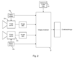
- Figure 2 shows a system including an image processor 21 according to one embodiment.
- the image processor receives image data from a plurality of image sensors 23a, 23b mounted on a platform such as the aircraft shown in Figure 1 .
- the image sensors 23a, 23b have separate fields of view that partially overlap with one another.
- the image processor 21 functions to combine the images received from each image sensor into a single combined image.
- the system shown in this example includes two image sensors 23a, 23b only.
- the image processor may be configured to receive images from further image sensors, where the total number of image sensors is such as to ensure a combined field of view covering the full 4 pi steradians of the aircraft's surroundings.
- each image sensor 23a, 23b may move relative to the other, for example as a result of engine/ propeller/rotor vibration, or variations in thrust due to variable air density entering the engine of the platform.
- each image sensor has an associated motion sensor 25a, 25b that is arranged to monitor shifts in position of the image sensor during the interval between capturing successive images.
- each motion sensor comprises a plurality of accelerometers that are used to monitor the acceleration of the image sensor in different directions. The velocity and displacement of the image sensor in each direction can be determined by integrating the measurements of acceleration with respect to time.
- each motion sensor comprises 4 three-axis accelerometers, allowing 12 measurements of linear acceleration, with the 4 accelerometers being arranged in a non-planar configuration (i.e. a configuration in which the accelerometers are not all located in a single plane). Then, by using the method disclosed by A. J. Padgaonkar, both the linear and angular motion of the respective image sensor can be determined with reduced computing power.
- the entire hull will be subject to accelerations as the aircraft performs various manoeuvres (roll, pitch, yaw etc.) These accelerations may also be registered by the motion sensors associated with the individual image sensors.
- the image processor In order to register the images from each image sensor correctly, the image processor must dissociate the motion that each image sensor undergoes relative to the aircraft (i.e. that which arises from the local shifts and / or vibrations of the particular part of the hull to which the image sensor is attached) from the motion of the aircraft as a whole.
- the image processor includes a further input that receives motion data 27 from a reference motion sensor affixed to the aircraft.
- the reference motion sensor may, for example, comprise part of the aircraft's inertial navigation system.
- the image processor uses the reference motion data together with the motion data received from the respective image sensor to calculate a local displacement undergone by the image sensor during the interval between capturing the first and second images.
- a local coordinate frame is defined inside the aircraft, and by combining the reference motion data with the individual image sensor data, the image processor is able to determine the shift in position of the image sensor in the local coordinate frame.
- FIG. 3 shows the components of the image processor of the present embodiment in more detail.
- the image processor 21 has a first port 31 through which image data from the image sensors is input to the processor, and a second port 33 through which the motion data from the motion sensors is input into the processor.
- a third port 35 is provided to receive the reference motion data.
- a data analyser 37 is used to identify the image sensor from which a particular image has been received, and which of the two motion sensors a particular batch of motion data is received from.
- the data analyser forwards each batch of motion data to a motion determining unit 39, which also receives the reference motion data.
- the motion determining unit 39 calculates the net displacement that the image sensor has undergone in the local coordinate frame of the aircraft in the interval since the last image was captured.
- the displacement is output as position data to an image adjustment module 41, which uses the data to process the received images in such a way as to compensate for the movement of the respective image sensor.
- the image adjustment module 41 may perform one or more of laterally shifting the rows or columns of pixels in the image, rotating the image, or adjusting the magnification of the image.
- the adjusted images are output to the image combining module 43 where they are combined into a single image 45 to be output for display to the pilot.
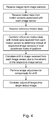
- Figure 4 shows a flow chart of the steps implemented by the image processor of the present embodiment.
- the motion sensors sense the movement of the respective image sensor by use of accelerometers and / or gyroscopes.
- Accelerometers provide measurements of instantaneous (linear) acceleration and gyroscopes provide measurements of instantaneous angular velocity. In order to derive angular positional information, it is necessary to integrate one or other of these measurements. However, where an accelerometer has a zero error in one or more axes, the error will be propagated through the calculation, resulting in a drift in the apparent angular position of the sensor.
- the measurements of acceleration may be complemented by optical flow measurements.
- Optical flow is an established technique that can provide direct measurements of the angular velocity of the image sensor and which can be used to correct for drifts in angular velocity / position as calculated using the data from the accelerometers. By measuring the angular positions of distant objects in the fields of view of more than one sensor (in the overlap region between two sensors), this correction can be transferred between sensors.
- optical flow measurements can provide the angular position of features in the scene, but only to an accuracy of about a pixel.
- the use of optical flow provides additional data that is complementary to that obtained from the accelerometers, as the accelerometer may be sensitive to rapid changes that may be too small to be visible in the imagery.
- Figure 5A shows an arrangement in which images 51, 53 captured by two image sensors 55, 57 at a first point in time are combined in a conventional image processor 59 to form a single output image 61.
- the image sensors 55, 57 have partially overlapping fields of view; as shown by the dotted lines, a portion 63 of the right hand side of the image 51 from the first image sensor 55 overlaps with a portion 65 on the left hand side of the image from the second image sensor 57.
- the images show the shape of the horizon as seen from an aircraft.
- Figure 5B shows a second pair of images 67, 69 that are captured by the first 55 and second 57 image sensors at a later moment in time.
- the second image sensor 57 undergoes a shift in its position.
- the field of view of the second image sensor 57 changes, producing an artefact in the combined image 71.
- the two halves of the combined image 71 are offset with respect to one another, giving a false impression of the landscape.
- the artefact is particularly evident in the region of overlap 71 a between the two images.
- Figure 6 shows an example of how the images from two sensors 73, 75 may be processed using an image processor 77 according to an embodiment.
- the image processor 77 is again used to combine pairs of images that are captured by the two image sensors.
- Figure 6A shows a first pair of images 79, 81 that are captured by the image sensors 73, 75 at a first point in time
- Figure 6B shows a second pair of images 83, 85 that have been captured at a later point in time.
- the second image sensor 75 undergoes a shift in position which causes a change in the field of view of the image 85 that is captured at the later time point.
- the image processor receives motion data 87 indicating the motion of the respective image sensors 73, 75 in the interval between capturing each pair of images. Using this motion data 87, the image processor 77 is able to compensate for the movement of the second image sensor 75 when combining the two images 83, 85 together.
- the output image remains free of artefacts, even though the field of view of the second image sensor 75 has changed: as can be seen in Figure 6B , the two halves of the image are perfectly aligned in the overlapping region.
- embodiments described herein can allow for the use of parallax correction to provide additional range information for objects that are present in the region of overlap between the fields of view of the respective image sensors. For example, some objects will not appear in the "correct" position for distant objects when their positions are measured in more than one sensor. These will be nearby objects, which can include objects passing the platform and the ground. Since the baseline is always known for any pair of sensors, embodiments permit the use of parallax techniques to measure of distance to these objects. For example, nearby objects can be ranged using the parallax between two adjacent sensor fields of view.
- An application of this could be in "dusty landings" where a rotary wing platform slows to a hover just above the ground and descends vertically.
- the height above the surface can be determined by using parallax between images captured from several image sensors.
- the change in height as the platform descends can be monitored by using optical flow measurements correlating surface features in successive image frames captured by a single downward-looking sensor. In this way, a more accurate determination of height above ground and descent rate can be made.
- the two sensors capturing images have simultaneous integrations (i.e. the image sensors should capture their respective images simultaneously).
- the image frame rate is high enough, it may be possible to obtain satisfactory results using non-simultaneous integrations for parallax measurements of stationary objects on the ground, but not for objects passing the platform.
- the optical flow measurements that are then used to measure the change in height need not require simultaneous integrations. For example once the height above ground has been determined using parallax, the optical flow measurements that are then carried out only need imagery from one sensor (i.e. the downward-pointing sensor) in order to determine the change in height and therefore rate of descent.
Landscapes
- Engineering & Computer Science (AREA)
- Multimedia (AREA)
- Signal Processing (AREA)
- Physics & Mathematics (AREA)
- General Physics & Mathematics (AREA)
- Theoretical Computer Science (AREA)
- Radar, Positioning & Navigation (AREA)
- Remote Sensing (AREA)
- Image Processing (AREA)
- Studio Devices (AREA)
- Electromagnetism (AREA)
Abstract
Description
- The present invention relates to an image processor for processing images received from a plurality of image sensors.
- When piloting or operating a vehicle, it is desirable to maintain as extensive a view of the vehicle's external environment as possible. This is particularly true in military scenarios when performing surveillance, for example, or during combat situations where the operator or crew need to be alert to threats emanating from all directions. The same is also true for aircraft and sea-going vessels.
- In order to maximise the visual data available, image sensors may be attached at various parts of the platform. The images received from each sensor can be combined into a single image of the surrounding environment. As the number of image sensors increases, it becomes possible to build up a panoramic view of the platform surroundings.
- In order to avoid introducing artefacts into the combined image, it is important to ensure the images received from each sensor are properly aligned with one another. It follows that there is a need to ensure that the images received from each sensor remain correctly aligned over extended periods of time.
- A first embodiment comprises an image processor for processing images received from a plurality of image sensors affixed to a platform, each image sensor having a field of view that at least partially overlaps with the field of view of another one of the other image sensors, the image processor comprising:
- an image data input for receiving a respective first image captured by each one of the plurality of image sensors and a respective second image subsequently captured by each one of the plurality of image sensors;
- a first motion data input for receiving motion data from a plurality of motion sensors, each motion sensor being associated with a respective one of the image sensors and configured to detect motion of the respective image sensor,
- a second motion data input for receiving reference motion data from a reference motion sensor located onboard the platform;
- a motion determining unit configured to determine, based on the motion data received from each image sensor and the reference motion data, whether or not the respective image sensor has moved from an expected position during the interval between capturing the first and second images, and to output position data indicating the change in position of the respective image sensor from its expected position;
- an image adjustment module configured to use the position data to adjust the second image received from the respective image sensor, to thereby provide a respective adjusted image; and
- an image combining module for combining each one of the adjusted images to form a single output image.
- The term "platform" as used in the present application can be understood to refer to any one of a vehicle, aircraft (fixed or rotary wing) or vessel (e.g. a ship). The term "platform" may also refer to a static structure, such as a structure protecting a military base.
- For each image sensor, the expected position may be the position of the respective image sensor in the local coordinate frame of the platform at the point at which the previous set of position data was calculated for that sensor.
- A second embodiment comprises a system for combining images received from image sensors positioned at different points around a platform in order to generate an image of the platform surroundings, the system comprising:
- a plurality of image sensors, each image sensor being configured to output a respective first and second image;
- a plurality of motion sensors, each motion sensor being associated with a respective one of the image sensors and configured to detect motion of the associated image sensor during the interval between capturing the first and second images; and
- an image processor according to the first embodiment.
- In some embodiments, each motion sensor may comprise one or more accelerometers and / or gyroscopes. For example, each motion sensor may comprise a three-axis accelerometer.
- In some embodiments, the image sensors may be synchronised to begin image capture at the same time as one another. The image sensors may be synchronised to output each captured image at the same time as one another. The image sensors may each have the same exposure or camera integration time. The image sensors may be triggered by a common trigger. The common trigger may be provided by the image processor.
- In some embodiments, the image processor includes a data analyser that is configured to identify the image sensor from which each one of the received images originates. The data analyser may be configured to identify which one of the image sensors a particular batch of motion data is associated with. The data analyser may pair the image data received from a respective image sensor with the motion data associated with that image sensor, to ensure that the image adjustment module uses the correct batch of motion data for processing each received image.
- A third embodiment comprises a platform comprising an image processor according to the second embodiment. The plurality of image sensors may be arranged at different locations around the platform, so as to provide a panoramic view of the platform surroundings.
- A fourth embodiment comprises a method of processing images received from a plurality of image sensors affixed to a platform, each image sensor having a field of view that at least partially overlaps with the field of view of another one of the other image sensors, the method comprising:
- receiving a respective first image captured by each one of the plurality of image sensors and a respective second image subsequently captured by each one of the plurality of image sensors;
- receiving motion data from a plurality of motion sensors, each motion sensor being associated with a respective one of the image sensors and configured to detect motion of the respective image sensor,
- receiving reference motion data from a reference motion sensor located onboard the platform;
- determining, based on the motion data received from each image sensor and the reference motion data, whether or not the respective image sensor has moved from an expected position during the interval between capturing the first and second images,
- outputting position data indicating the change in position of the respective image sensor from its expected position;
- using the position data to adjust the second image received from the respective image sensor, to thereby provide a respective adjusted image; and
- combining each one of the adjusted images to form a single output image.
- A fifth embodiment comprises a computer readable storage medium storing computer executable code that when executed by a computer will cause the computer to carry out a method according to the fourth embodiment.
- In some embodiments, the image adjustment module is configured to use the position data to determine a change in the field of view of the respective image sensor.
- In some embodiments, each image captured by the image sensors is time stamped to show the time at which the image is captured. The time stamp may correspond to the beginning or end of the respective image sensor integration period.
- If the system is producing imagery to be viewed by human beings, there is no need for the combined image that is output by the image processor to be updated at a rate above about 100 Hz. Instead, the frequency at which the combined image is updated need only be above the flicker frequency. Therefore, in cases where the image sensors output individual frames at rates in excess of 100Hz, it may not be necessary to combine each individual image that is received from those sensors. Time-stamping the images is useful in that it can allow the image processor to determine which images are to be combined, and which ones need not be combined. Time-stamping the images may also help the processor to coordinate different processes being carried out on frames that have been captured at different times. For example, whilst some image frames are being combined in the image combining module, the image processor may perform other processing tasks on image frames that have been captured at a different point in time. For example, the image processor may superimpose other data on the images, such as threat types and locations using information derived from all the collected imagery, not just the images that are combined.
- Each image sensor may be wired directly to the image processor. For example, the image sensors may be wired by point-to-point wiring. Alternatively, the sensors and the image processor may all be connected to a data bus. As a further alternative, the image sensors may communicate wirelessly with the image processor.
- In some embodiments, each image sensor comprises a CCD chip or a CMOS device. The CCD chip or CMOS device may have an array of 256 x 256 pixels, for example. In order to increase the field of view in one direction, a rectangular array of pixels may be used. For example, in order to increase the size of the field of view in the horizontal direction, the CCD chip may comprise a 320 x 256 array of pixels. In some embodiments, the CCD chip may be configurable to use a sub-array of the physical array for imaging. For example, the CCD chip may have a physical array of 320 x 256 pixels but only use a sub-array of 256 x 256 pixels for imaging.
- The image sensors may be configured to sense radiation having a wavelength in the range 0.3 µm to 30 µm, the atmosphere being transparent to radiation at these wavelengths. More particularly, the image sensors may have an increased relative sensitivity to wavelengths in the range 0.3 µm to 14 µm. In some embodiments, the wavelength sensitivity may be obtained by selecting materials having a suitable bandgap for the CCD chip. In some embodiments, the wavelength sensitivity may be provided by use of filters in front of the sensor array. For example, interference filters having pass bands in the infra-red region of the spectrum may be used.
- In some embodiments, the image adjustment module is configured to perform at least one of translating, rotating, and magnifying each received image based on the position data.
- In some embodiments, combining the images into an output image comprises generating a single array of pixel intensity and/or hue values. Where the field of view of the image sensors partially overlap with one another, combining the images may comprise generating a single pixel intensity and/or hue value for each pixel in the region of overlap.
- In some embodiments, the system may comprise four image sensors arranged on a platform, with their optical axes in a horizontal plane. In some embodiments, each image sensor may be arranged with its optical axis angled at 45 degrees to the forward direction of motion of the platform. Additional sensors may be provided having their optical axes arranged vertically, with one pointing up and one pointing down, for example. Each image sensor may have a field of view of 105 degrees x 105 degrees, providing an overlap between each sensor field of view and so removing the possibility of blind spots. Further image sensors may be added to the system, particularly if the design of the platform is such that parts of the hull obscure the fields of view of some of the image sensors. In some embodiments, the image sensors may be arranged such that the combined image output from the image processor comprises the full 4 pi steradians of the platform surroundings.
- In some embodiments, for each image sensor, the image processor may be configured to use the optical flow of features identified in the first and second images to determine an angular velocity of the respective image sensor. The optical flow measurements may be combined with the data received from the respective motion sensors to more accurately determine a displacement of the image sensor in the interval between capturing the first and second images.
- Each image sensor and its associated motion sensor may be housed together in a single respective unit that is then mounted at a specific location on the platform.
- Embodiments of the invention will now be described by way of example with reference to the accompanying drawings in which:
-
Figure 1 shows an example of an aircraft including an image processor according to an embodiment; -
Figure 2 shows a system including an image processor according to an embodiment; -
Figure 3 shows the components of the image processor ofFigure 2 in more detail; -
Figure 4 shows a flow chart of steps implemented by the image processor ofFigure 1 ; -
Figure 5 shows an example of combining images received from two sensors into a single image using a conventional image processor; and -
Figure 6 shows an example of combining images received from two sensors into a single image using an embodiment described herein. -
Figure 1 shows an example of an aircraft in accordance with an embodiment. The aircraft hull is formed from a number ofdiscrete parts respective image sensor - Included within the aircraft is an
image processor 13 that receives image data from each image sensor and combines the received image data into a single panoramic view of the aircraft's surroundings. The combined image can then be viewed by the pilot on a display screen. The display screen may contain additional information as well as imagery e.g. alphanumerics, symbols etc. In the present embodiment, the image processor is connected to each one of the image sensors via a local network or bus that mediates communication between the different computer subsystems of the aircraft. However, other alternatives are envisaged; for example, the image processor may communicate wirelessly with each image sensor. - During flight, the discrete parts of the hull may undergo stress to different extents, causing them to vibrate or shift relative to one another. The alignment between the image sensors may vary over time, as one part of the hull moves with respect to another. As a result, the images captured from each sensor will no longer be registered correctly. In order to avoid artefacts appearing in the combined image, therefore, the image processor calibrates for the movement of the images sensors before combining the images with one another.
- Examples of how the image processor achieves correct registration of the images will now be described by reference to
Figures 2 to 6 . -
Figure 2 shows a system including animage processor 21 according to one embodiment. The image processor receives image data from a plurality ofimage sensors Figure 1 . Theimage sensors image processor 21 functions to combine the images received from each image sensor into a single combined image. - For simplicity, the system shown in this example includes two
image sensors - During the interval between capturing successive images, one of the
image sensors motion sensor - To define fully the motion of the image sensor, it is necessary to determine its linear motion in three orthogonal axes and its rotation about three orthogonal axes. In theory, it is possible to do so using a minimum of 6 measurements. However, such an approach involves a significant degree of complexity in the calculation. To simplify the computation, an alternative approach such as that suggested by A. J. Padgaonkar et al can be used (see "Measurement of angular acceleration of a rigid body using linear accelerometers", by A. J. Padgaonkar et al in J. Appl. Mech. September 1975, Volume 42, Issue 3, p 552 - 557). In this approach, at least 3 additional measurements of acceleration may be made (taking the total to 9 measurements). In the present embodiment, each motion sensor comprises 4 three-axis accelerometers, allowing 12 measurements of linear acceleration, with the 4 accelerometers being arranged in a non-planar configuration (i.e. a configuration in which the accelerometers are not all located in a single plane). Then, by using the method disclosed by A. J. Padgaonkar, both the linear and angular motion of the respective image sensor can be determined with reduced computing power.
- During flight of the aircraft, the entire hull will be subject to accelerations as the aircraft performs various manoeuvres (roll, pitch, yaw etc.) These accelerations may also be registered by the motion sensors associated with the individual image sensors. In order to register the images from each image sensor correctly, the image processor must dissociate the motion that each image sensor undergoes relative to the aircraft (i.e. that which arises from the local shifts and / or vibrations of the particular part of the hull to which the image sensor is attached) from the motion of the aircraft as a whole. In order to achieve this, the image processor includes a further input that receives
motion data 27 from a reference motion sensor affixed to the aircraft. The reference motion sensor may, for example, comprise part of the aircraft's inertial navigation system. - For each image sensor, the image processor uses the reference motion data together with the motion data received from the respective image sensor to calculate a local displacement undergone by the image sensor during the interval between capturing the first and second images. In effect, a local coordinate frame is defined inside the aircraft, and by combining the reference motion data with the individual image sensor data, the image processor is able to determine the shift in position of the image sensor in the local coordinate frame.
-
Figure 3 shows the components of the image processor of the present embodiment in more detail. Theimage processor 21 has afirst port 31 through which image data from the image sensors is input to the processor, and asecond port 33 through which the motion data from the motion sensors is input into the processor. Athird port 35 is provided to receive the reference motion data. - A
data analyser 37 is used to identify the image sensor from which a particular image has been received, and which of the two motion sensors a particular batch of motion data is received from. - The data analyser forwards each batch of motion data to a
motion determining unit 39, which also receives the reference motion data. For each image sensor, themotion determining unit 39 calculates the net displacement that the image sensor has undergone in the local coordinate frame of the aircraft in the interval since the last image was captured. The displacement is output as position data to animage adjustment module 41, which uses the data to process the received images in such a way as to compensate for the movement of the respective image sensor. - For each image, the
image adjustment module 41 may perform one or more of laterally shifting the rows or columns of pixels in the image, rotating the image, or adjusting the magnification of the image. Once the image adjustment has been performed, the adjusted images are output to theimage combining module 43 where they are combined into asingle image 45 to be output for display to the pilot. -
Figure 4 shows a flow chart of the steps implemented by the image processor of the present embodiment. - In some embodiments, the motion sensors sense the movement of the respective image sensor by use of accelerometers and / or gyroscopes. Accelerometers provide measurements of instantaneous (linear) acceleration and gyroscopes provide measurements of instantaneous angular velocity. In order to derive angular positional information, it is necessary to integrate one or other of these measurements. However, where an accelerometer has a zero error in one or more axes, the error will be propagated through the calculation, resulting in a drift in the apparent angular position of the sensor.
- In order to address this problem, the measurements of acceleration may be complemented by optical flow measurements. Optical flow is an established technique that can provide direct measurements of the angular velocity of the image sensor and which can be used to correct for drifts in angular velocity / position as calculated using the data from the accelerometers. By measuring the angular positions of distant objects in the fields of view of more than one sensor (in the overlap region between two sensors), this correction can be transferred between sensors.
- In general, optical flow measurements can provide the angular position of features in the scene, but only to an accuracy of about a pixel. The use of optical flow provides additional data that is complementary to that obtained from the accelerometers, as the accelerometer may be sensitive to rapid changes that may be too small to be visible in the imagery.
- An example of how an image processor may be used to remove artefacts resulting from motion of one of the image sensors will now be described by reference to
Figures 5 and6 . -
Figure 5A shows an arrangement in whichimages image sensors conventional image processor 59 to form asingle output image 61. In this example, theimage sensors portion 63 of the right hand side of theimage 51 from thefirst image sensor 55 overlaps with aportion 65 on the left hand side of the image from thesecond image sensor 57. Together, the images show the shape of the horizon as seen from an aircraft. -
Figure 5B shows a second pair ofimages second image sensor 57 undergoes a shift in its position. As a result, the field of view of thesecond image sensor 57 changes, producing an artefact in the combinedimage 71. Specifically, the two halves of the combinedimage 71 are offset with respect to one another, giving a false impression of the landscape. The artefact is particularly evident in the region ofoverlap 71 a between the two images. -
Figure 6 shows an example of how the images from twosensors image processor 77 according to an embodiment. Theimage processor 77 is again used to combine pairs of images that are captured by the two image sensors.Figure 6A shows a first pair ofimages image sensors Figure 6B shows a second pair ofimages - As in
Figure 5 , thesecond image sensor 75 undergoes a shift in position which causes a change in the field of view of theimage 85 that is captured at the later time point. However, in the present embodiment, the image processor receivesmotion data 87 indicating the motion of therespective image sensors motion data 87, theimage processor 77 is able to compensate for the movement of thesecond image sensor 75 when combining the twoimages Figure 5B , the output image remains free of artefacts, even though the field of view of thesecond image sensor 75 has changed: as can be seen inFigure 6B , the two halves of the image are perfectly aligned in the overlapping region. - In ensuring that each image sensor is correctly aligned, embodiments described herein can allow for the use of parallax correction to provide additional range information for objects that are present in the region of overlap between the fields of view of the respective image sensors. For example, some objects will not appear in the "correct" position for distant objects when their positions are measured in more than one sensor. These will be nearby objects, which can include objects passing the platform and the ground. Since the baseline is always known for any pair of sensors, embodiments permit the use of parallax techniques to measure of distance to these objects. For example, nearby objects can be ranged using the parallax between two adjacent sensor fields of view.
- An application of this could be in "dusty landings" where a rotary wing platform slows to a hover just above the ground and descends vertically. First, the height above the surface can be determined by using parallax between images captured from several image sensors. Then, the change in height as the platform descends can be monitored by using optical flow measurements correlating surface features in successive image frames captured by a single downward-looking sensor. In this way, a more accurate determination of height above ground and descent rate can be made.
- When using parallax to determine the height of the rotary wing platform from the ground, it is preferable that the two sensors capturing images have simultaneous integrations (i.e. the image sensors should capture their respective images simultaneously). In practice, provided the image frame rate is high enough, it may be possible to obtain satisfactory results using non-simultaneous integrations for parallax measurements of stationary objects on the ground, but not for objects passing the platform. The optical flow measurements that are then used to measure the change in height need not require simultaneous integrations. For example once the height above ground has been determined using parallax, the optical flow measurements that are then carried out only need imagery from one sensor (i.e. the downward-pointing sensor) in order to determine the change in height and therefore rate of descent.
- While certain embodiments have been described, these embodiments have been presented by way of example only, and are not intended to limit the scope of the invention. Indeed, the novel methods, devices and systems described herein may be embodied in a variety of forms. Furthermore, various omissions, substitutions and changes in the form of the methods and systems described herein may be made without departing from the spirit of the invention. The accompanying claims and their equivalents are intended to cover such forms or modifications as would fall within the scope of the invention.
Claims (15)
- An image processor for processing images received from a plurality of image sensors affixed to a platform, each image sensor having a field of view that at least partially overlaps with the field of view of another one of the other image sensors, the image processor comprising:an image data input for receiving a respective first image captured by each one of the plurality of image sensors and a respective second image subsequently captured by each one of the plurality of image sensors;a first motion data input for receiving motion data from a plurality of motion sensors, each motion sensor being associated with a respective one of the image sensors and configured to detect motion of the respective image sensor,a second motion data input for receiving reference motion data from a reference motion sensor located onboard the platform;a motion determining unit configured to determine, based on the motion data received from each image sensor and the reference motion data, whether or not the respective image sensor has moved from an expected position during the interval between capturing the first and second images, and to output position data indicating the change in position of the respective image sensor from its expected position;an image adjustment module configured to use the position data to adjust the second image received from the respective image sensor, to thereby provide a respective adjusted image; andan image combining module for combining each one of the adjusted images to form a single output image.
- An image processor according to claim 1, wherein the image adjustment module is configured to determine a change in the field of view of a respective image sensor based on the motion data associated with the image sensor.
- An image processor according to claim 1 or 2, wherein the image adjustment module is configured to perform at least one of translating, rotating, and magnifying the second image based on the received position data.
- An image processor according to any one of claims 1 to 3 wherein the image sensors are synchronised to begin image capture at the same time as one another.
- An image processor according to any one of the preceding claims wherein the image sensors are synchronised to output each captured image at the same time as one another and / or wherein the image sensors each have the same exposure or camera integration time.
- An image processor according to any one of claims 4 to 5, wherein the image processor is configured to trigger the image sensors to begin capturing each image.
- An image processor according to any one of the preceding claims, wherein the image combining module is configured to combine the adjusted images into an output image by generating a single array of pixel intensity and/or hue values.
- An image processor according to any one of the preceding claims, wherein for each image sensor, the image processor is configured to use the optical flow of features identified in the first and second images to determine an angular velocity of the respective image sensor.
- A system for combining images received from image sensors positioned at different points around a platform in order to generate an image of the platform surroundings, the system comprising:a plurality of image sensors, each image sensor being configured to output a respective first and second image;a plurality of motion sensors, each motion sensor being associated with a respective one of the image sensors and configured to detect motion of the associated image sensor during the interval between capturing the first and second images; andan image processing module according to the any one of the preceding claims.
- A system according to claim 9, wherein each motion sensor comprises one or more accelerometers.
- A system according to claim 9 or 10 wherein the image sensors are synchronised to capture and output images simultaneously with one another and / or wherein each image sensor comprises a CCD chip or a CMOS device.
- A system according to any one of claims 9 to 11, wherein the image sensors are configured to sense radiation having a wavelength in the range 0.3 µm to 30 µm.
- A platform comprising a system according to any one of claims 9 to 12.
- A method of processing images received from a plurality of image sensors affixed to a platform, each image sensor having a field of view that at least partially overlaps with the field of view of another one of the other image sensors, the method comprising:receiving a respective first image captured by each one of the plurality of image sensors and a respective second image subsequently captured by each one of the plurality of image sensors;receiving motion data from a plurality of motion sensors, each motion sensor being associated with a respective one of the image sensors and configured to detect motion of the respective image sensor,receiving reference motion data from a reference motion sensor located onboard the platform;determining, based on the motion data received from each image sensor and the reference motion data, whether or not the respective image sensor has moved from an expected position during the interval between capturing the first and second images,outputting position data indicating the change in position of the respective image sensor from its expected position;using the position data to adjust the second image received from the respective image sensor, to thereby provide a respective adjusted image; andcombining each one of the adjusted images to form a single output image.
- A computer readable storage medium storing computer executable code that when executed by a computer will cause the computer to carry out a method according to claim 14.
Applications Claiming Priority (1)
| Application Number | Priority Date | Filing Date | Title |
|---|---|---|---|
| GB1223051.2A GB2509102B (en) | 2012-12-20 | 2012-12-20 | Image processor for processing images received from a plurality of image sensors |
Publications (2)
| Publication Number | Publication Date |
|---|---|
| EP2747418A1 true EP2747418A1 (en) | 2014-06-25 |
| EP2747418B1 EP2747418B1 (en) | 2016-03-23 |
Family
ID=47843472
Family Applications (1)
| Application Number | Title | Priority Date | Filing Date |
|---|---|---|---|
| EP13198869.3A Active EP2747418B1 (en) | 2012-12-20 | 2013-12-20 | Image processor for processing images received from a plurality of image sensors |
Country Status (5)
| Country | Link |
|---|---|
| US (1) | US20140176726A1 (en) |
| EP (1) | EP2747418B1 (en) |
| DK (1) | DK2747418T3 (en) |
| ES (1) | ES2569390T3 (en) |
| GB (1) | GB2509102B (en) |
Cited By (2)
| Publication number | Priority date | Publication date | Assignee | Title |
|---|---|---|---|---|
| US20160073021A1 (en) * | 2014-09-05 | 2016-03-10 | Htc Corporation | Image capturing method, panorama image generating method and electronic apparatus |
| CN108028889A (en) * | 2015-09-18 | 2018-05-11 | 索尼公司 | Image processing equipment, image processing method, program and camera system |
Families Citing this family (9)
| Publication number | Priority date | Publication date | Assignee | Title |
|---|---|---|---|---|
| DE102013204935A1 (en) * | 2013-03-20 | 2014-09-25 | Robert Bosch Gmbh | Method and device for taking a picture of a pulsed lighting object |
| EP3014579B1 (en) * | 2014-04-30 | 2018-09-26 | Intel Corporation | System and method of limiting processing by a 3d reconstruction system of an environment in a 3d reconstruction of an event occurring in an event space |
| US10235817B2 (en) * | 2015-09-01 | 2019-03-19 | Ford Global Technologies, Llc | Motion compensation for on-board vehicle sensors |
| JP6332212B2 (en) * | 2015-09-18 | 2018-05-30 | カシオ計算機株式会社 | Posture estimation apparatus, posture estimation method, and program |
| US10633095B2 (en) * | 2016-04-04 | 2020-04-28 | Panasonic Intellectual Property Management Co., Ltd. | Imaging system, video processing system, and video processing method |
| US10515390B2 (en) * | 2016-11-21 | 2019-12-24 | Nio Usa, Inc. | Method and system for data optimization |
| US11227382B2 (en) * | 2018-01-11 | 2022-01-18 | Intelinair, Inc. | Change detection system |
| US20210250481A1 (en) * | 2018-04-27 | 2021-08-12 | Arizona Board Of Regents On Behalf Of The University Of Arizona | Rotationally Shift Invariant and Multi-Layered Microlens Array |
| EP3925207A4 (en) * | 2019-02-12 | 2022-11-09 | Commonwealth Scientific and Industrial Research Organisation | Situational awareness monitoring |
Citations (5)
| Publication number | Priority date | Publication date | Assignee | Title |
|---|---|---|---|---|
| US5317394A (en) * | 1992-04-30 | 1994-05-31 | Westinghouse Electric Corp. | Distributed aperture imaging and tracking system |
| US5448290A (en) * | 1991-08-23 | 1995-09-05 | Go-Video Inc. | Video security system with motion sensor override, wireless interconnection, and mobile cameras |
| DE4420422A1 (en) * | 1994-06-10 | 1995-12-14 | Dickmanns Ernst Dieter Prof Dr | Technically complex artificial eye for dynamic automatic vision |
| US20070188653A1 (en) * | 2006-02-13 | 2007-08-16 | Pollock David B | Multi-lens array system and method |
| US20120306999A1 (en) * | 2011-06-01 | 2012-12-06 | Apple Inc. | Motion-Based Image Stitching |
Family Cites Families (3)
| Publication number | Priority date | Publication date | Assignee | Title |
|---|---|---|---|---|
| EP1860867A1 (en) * | 2006-05-24 | 2007-11-28 | STMicroelectronics (Research & Development) Limited | Panoramic camera |
| US7805020B2 (en) * | 2006-07-25 | 2010-09-28 | Itt Manufacturing Enterprises, Inc. | Motion compensated image registration for overlaid/fused video |
| CN102959943B (en) * | 2010-06-24 | 2016-03-30 | 富士胶片株式会社 | Stereoscopic panoramic image synthesizer and method and image capture apparatus |
-
2012
- 2012-12-20 GB GB1223051.2A patent/GB2509102B/en active Active
-
2013
- 2013-12-20 US US14/137,962 patent/US20140176726A1/en not_active Abandoned
- 2013-12-20 DK DK13198869.3T patent/DK2747418T3/en active
- 2013-12-20 EP EP13198869.3A patent/EP2747418B1/en active Active
- 2013-12-20 ES ES13198869.3T patent/ES2569390T3/en active Active
Patent Citations (5)
| Publication number | Priority date | Publication date | Assignee | Title |
|---|---|---|---|---|
| US5448290A (en) * | 1991-08-23 | 1995-09-05 | Go-Video Inc. | Video security system with motion sensor override, wireless interconnection, and mobile cameras |
| US5317394A (en) * | 1992-04-30 | 1994-05-31 | Westinghouse Electric Corp. | Distributed aperture imaging and tracking system |
| DE4420422A1 (en) * | 1994-06-10 | 1995-12-14 | Dickmanns Ernst Dieter Prof Dr | Technically complex artificial eye for dynamic automatic vision |
| US20070188653A1 (en) * | 2006-02-13 | 2007-08-16 | Pollock David B | Multi-lens array system and method |
| US20120306999A1 (en) * | 2011-06-01 | 2012-12-06 | Apple Inc. | Motion-Based Image Stitching |
Cited By (9)
| Publication number | Priority date | Publication date | Assignee | Title |
|---|---|---|---|---|
| US20160073021A1 (en) * | 2014-09-05 | 2016-03-10 | Htc Corporation | Image capturing method, panorama image generating method and electronic apparatus |
| US9986155B2 (en) * | 2014-09-05 | 2018-05-29 | Htc Corporation | Image capturing method, panorama image generating method and electronic apparatus |
| CN108028889A (en) * | 2015-09-18 | 2018-05-11 | 索尼公司 | Image processing equipment, image processing method, program and camera system |
| JPWO2017047219A1 (en) * | 2015-09-18 | 2018-06-28 | ソニー株式会社 | Image processing apparatus, image processing method, program, and imaging system |
| EP3352448A4 (en) * | 2015-09-18 | 2019-04-24 | Sony Corporation | Image processing device, image processing method, program and imaging system |
| US10574884B2 (en) | 2015-09-18 | 2020-02-25 | Sony Corporation | Image processing apparatus, image processing method, program, and image pickup system |
| US10917567B2 (en) | 2015-09-18 | 2021-02-09 | Sony Corporation | Image processing apparatus, image processing method, program, and image pickup system |
| CN108028889B (en) * | 2015-09-18 | 2021-07-02 | 索尼公司 | Image processing apparatus, image processing method, program, and imaging system |
| US11381740B2 (en) | 2015-09-18 | 2022-07-05 | Sony Group Corporation | Image processing apparatus, image processing method, program, and image pickup system |
Also Published As
| Publication number | Publication date |
|---|---|
| GB2509102B (en) | 2015-09-02 |
| GB201223051D0 (en) | 2013-03-06 |
| ES2569390T3 (en) | 2016-05-10 |
| EP2747418B1 (en) | 2016-03-23 |
| DK2747418T3 (en) | 2016-07-04 |
| US20140176726A1 (en) | 2014-06-26 |
| GB2509102A (en) | 2014-06-25 |
Similar Documents
| Publication | Publication Date | Title |
|---|---|---|
| EP2747418B1 (en) | Image processor for processing images received from a plurality of image sensors | |
| CN107850436B (en) | Sensor fusion using inertial and image sensors | |
| CN107850901B (en) | Sensor fusion using inertial and image sensors | |
| CN111792034B (en) | Method and system for estimating state information of movable object using sensor fusion | |
| CA2680813C (en) | System for panoramic image processing | |
| CN107850899B (en) | Sensor fusion using inertial and image sensors | |
| KR20110027654A (en) | Systems and methods of capturing large area images in detail including cascaded cameras and/or calibration features | |
| JP2019528501A (en) | Camera alignment in a multi-camera system | |
| KR20170047230A (en) | Stabilization and display of remote images | |
| CN107270900A (en) | A kind of 6DOF locus and the detecting system and method for posture | |
| WO2020061857A1 (en) | Autofocusing camera and systems | |
| JP2008311690A (en) | Eyeball movement controller employing principle of vestibulo-ocular reflex | |
| CN102654917B (en) | Method and system for sensing motion gestures of moving body | |
| KR20180046803A (en) | Unmanned surface vehicle control system for providing wide viewing angle using real camera image and virtual camera image | |
| Palonen et al. | Augmented reality in forest machine cabin | |
| US7839490B2 (en) | Single-aperture passive rangefinder and method of determining a range | |
| Matej | Determination of forestry machine’s tilt angle using camera and image processing | |
| KR101183645B1 (en) | System for measuring attitude of aircraft using camera and method therefor | |
| CN202084081U (en) | Moving object motion attitude sensing system | |
| JPH10153426A (en) | Topography measuring device | |
| JP7169940B2 (en) | Drawing superimposing device and program | |
| US10802276B2 (en) | Display system, related display method and computer program | |
| JP6813046B2 (en) | Image flow correction device, image flow correction method and program | |
| US20230215164A1 (en) | Radar and colocated camera systems and methods | |
| JP7084716B2 (en) | Flight data recording system |
Legal Events
| Date | Code | Title | Description |
|---|---|---|---|
| PUAI | Public reference made under article 153(3) epc to a published international application that has entered the european phase |
Free format text: ORIGINAL CODE: 0009012 |
|
| 17P | Request for examination filed |
Effective date: 20131220 |
|
| AK | Designated contracting states |
Kind code of ref document: A1 Designated state(s): AL AT BE BG CH CY CZ DE DK EE ES FI FR GB GR HR HU IE IS IT LI LT LU LV MC MK MT NL NO PL PT RO RS SE SI SK SM TR |
|
| AX | Request for extension of the european patent |
Extension state: BA ME |
|
| GRAP | Despatch of communication of intention to grant a patent |
Free format text: ORIGINAL CODE: EPIDOSNIGR1 |
|
| INTG | Intention to grant announced |
Effective date: 20150917 |
|
| GRAS | Grant fee paid |
Free format text: ORIGINAL CODE: EPIDOSNIGR3 |
|
| GRAA | (expected) grant |
Free format text: ORIGINAL CODE: 0009210 |
|
| AK | Designated contracting states |
Kind code of ref document: B1 Designated state(s): AL AT BE BG CH CY CZ DE DK EE ES FI FR GB GR HR HU IE IS IT LI LT LU LV MC MK MT NL NO PL PT RO RS SE SI SK SM TR |
|
| REG | Reference to a national code |
Ref country code: GB Ref legal event code: FG4D |
|
| REG | Reference to a national code |
Ref country code: CH Ref legal event code: EP |
|
| REG | Reference to a national code |
Ref country code: AT Ref legal event code: REF Ref document number: 784161 Country of ref document: AT Kind code of ref document: T Effective date: 20160415 |
|
| REG | Reference to a national code |
Ref country code: IE Ref legal event code: FG4D |
|
| REG | Reference to a national code |
Ref country code: ES Ref legal event code: FG2A Ref document number: 2569390 Country of ref document: ES Kind code of ref document: T3 Effective date: 20160510 |
|
| REG | Reference to a national code |
Ref country code: DE Ref legal event code: R096 Ref document number: 602013005694 Country of ref document: DE |
|
| REG | Reference to a national code |
Ref country code: DK Ref legal event code: T3 Effective date: 20160627 |
|
| REG | Reference to a national code |
Ref country code: SE Ref legal event code: TRGR |
|
| REG | Reference to a national code |
Ref country code: LT Ref legal event code: MG4D |
|
| REG | Reference to a national code |
Ref country code: NL Ref legal event code: MP Effective date: 20160323 |
|
| PG25 | Lapsed in a contracting state [announced via postgrant information from national office to epo] |
Ref country code: FI Free format text: LAPSE BECAUSE OF FAILURE TO SUBMIT A TRANSLATION OF THE DESCRIPTION OR TO PAY THE FEE WITHIN THE PRESCRIBED TIME-LIMIT Effective date: 20160323 Ref country code: GR Free format text: LAPSE BECAUSE OF FAILURE TO SUBMIT A TRANSLATION OF THE DESCRIPTION OR TO PAY THE FEE WITHIN THE PRESCRIBED TIME-LIMIT Effective date: 20160624 Ref country code: NO Free format text: LAPSE BECAUSE OF FAILURE TO SUBMIT A TRANSLATION OF THE DESCRIPTION OR TO PAY THE FEE WITHIN THE PRESCRIBED TIME-LIMIT Effective date: 20160623 Ref country code: HR Free format text: LAPSE BECAUSE OF FAILURE TO SUBMIT A TRANSLATION OF THE DESCRIPTION OR TO PAY THE FEE WITHIN THE PRESCRIBED TIME-LIMIT Effective date: 20160323 |
|
| REG | Reference to a national code |
Ref country code: AT Ref legal event code: MK05 Ref document number: 784161 Country of ref document: AT Kind code of ref document: T Effective date: 20160323 |
|
| PG25 | Lapsed in a contracting state [announced via postgrant information from national office to epo] |
Ref country code: LT Free format text: LAPSE BECAUSE OF FAILURE TO SUBMIT A TRANSLATION OF THE DESCRIPTION OR TO PAY THE FEE WITHIN THE PRESCRIBED TIME-LIMIT Effective date: 20160323 Ref country code: NL Free format text: LAPSE BECAUSE OF FAILURE TO SUBMIT A TRANSLATION OF THE DESCRIPTION OR TO PAY THE FEE WITHIN THE PRESCRIBED TIME-LIMIT Effective date: 20160323 Ref country code: RS Free format text: LAPSE BECAUSE OF FAILURE TO SUBMIT A TRANSLATION OF THE DESCRIPTION OR TO PAY THE FEE WITHIN THE PRESCRIBED TIME-LIMIT Effective date: 20160323 Ref country code: LV Free format text: LAPSE BECAUSE OF FAILURE TO SUBMIT A TRANSLATION OF THE DESCRIPTION OR TO PAY THE FEE WITHIN THE PRESCRIBED TIME-LIMIT Effective date: 20160323 |
|
| PG25 | Lapsed in a contracting state [announced via postgrant information from national office to epo] |
Ref country code: EE Free format text: LAPSE BECAUSE OF FAILURE TO SUBMIT A TRANSLATION OF THE DESCRIPTION OR TO PAY THE FEE WITHIN THE PRESCRIBED TIME-LIMIT Effective date: 20160323 Ref country code: PL Free format text: LAPSE BECAUSE OF FAILURE TO SUBMIT A TRANSLATION OF THE DESCRIPTION OR TO PAY THE FEE WITHIN THE PRESCRIBED TIME-LIMIT Effective date: 20160323 Ref country code: IS Free format text: LAPSE BECAUSE OF FAILURE TO SUBMIT A TRANSLATION OF THE DESCRIPTION OR TO PAY THE FEE WITHIN THE PRESCRIBED TIME-LIMIT Effective date: 20160723 |
|
| REG | Reference to a national code |
Ref country code: FR Ref legal event code: PLFP Year of fee payment: 4 |
|
| PG25 | Lapsed in a contracting state [announced via postgrant information from national office to epo] |
Ref country code: PT Free format text: LAPSE BECAUSE OF FAILURE TO SUBMIT A TRANSLATION OF THE DESCRIPTION OR TO PAY THE FEE WITHIN THE PRESCRIBED TIME-LIMIT Effective date: 20160725 Ref country code: SM Free format text: LAPSE BECAUSE OF FAILURE TO SUBMIT A TRANSLATION OF THE DESCRIPTION OR TO PAY THE FEE WITHIN THE PRESCRIBED TIME-LIMIT Effective date: 20160323 Ref country code: RO Free format text: LAPSE BECAUSE OF FAILURE TO SUBMIT A TRANSLATION OF THE DESCRIPTION OR TO PAY THE FEE WITHIN THE PRESCRIBED TIME-LIMIT Effective date: 20160323 Ref country code: SK Free format text: LAPSE BECAUSE OF FAILURE TO SUBMIT A TRANSLATION OF THE DESCRIPTION OR TO PAY THE FEE WITHIN THE PRESCRIBED TIME-LIMIT Effective date: 20160323 Ref country code: CZ Free format text: LAPSE BECAUSE OF FAILURE TO SUBMIT A TRANSLATION OF THE DESCRIPTION OR TO PAY THE FEE WITHIN THE PRESCRIBED TIME-LIMIT Effective date: 20160323 Ref country code: AT Free format text: LAPSE BECAUSE OF FAILURE TO SUBMIT A TRANSLATION OF THE DESCRIPTION OR TO PAY THE FEE WITHIN THE PRESCRIBED TIME-LIMIT Effective date: 20160323 |
|
| PG25 | Lapsed in a contracting state [announced via postgrant information from national office to epo] |
Ref country code: BE Free format text: LAPSE BECAUSE OF FAILURE TO SUBMIT A TRANSLATION OF THE DESCRIPTION OR TO PAY THE FEE WITHIN THE PRESCRIBED TIME-LIMIT Effective date: 20160323 |
|
| REG | Reference to a national code |
Ref country code: DE Ref legal event code: R097 Ref document number: 602013005694 Country of ref document: DE |
|
| PLBE | No opposition filed within time limit |
Free format text: ORIGINAL CODE: 0009261 |
|
| STAA | Information on the status of an ep patent application or granted ep patent |
Free format text: STATUS: NO OPPOSITION FILED WITHIN TIME LIMIT |
|
| PG25 | Lapsed in a contracting state [announced via postgrant information from national office to epo] |
Ref country code: BG Free format text: LAPSE BECAUSE OF FAILURE TO SUBMIT A TRANSLATION OF THE DESCRIPTION OR TO PAY THE FEE WITHIN THE PRESCRIBED TIME-LIMIT Effective date: 20160623 |
|
| 26N | No opposition filed |
Effective date: 20170102 |
|
| PG25 | Lapsed in a contracting state [announced via postgrant information from national office to epo] |
Ref country code: SI Free format text: LAPSE BECAUSE OF FAILURE TO SUBMIT A TRANSLATION OF THE DESCRIPTION OR TO PAY THE FEE WITHIN THE PRESCRIBED TIME-LIMIT Effective date: 20160323 |
|
| REG | Reference to a national code |
Ref country code: CH Ref legal event code: PL |
|
| PG25 | Lapsed in a contracting state [announced via postgrant information from national office to epo] |
Ref country code: MC Free format text: LAPSE BECAUSE OF FAILURE TO SUBMIT A TRANSLATION OF THE DESCRIPTION OR TO PAY THE FEE WITHIN THE PRESCRIBED TIME-LIMIT Effective date: 20160323 |
|
| REG | Reference to a national code |
Ref country code: IE Ref legal event code: MM4A |
|
| PG25 | Lapsed in a contracting state [announced via postgrant information from national office to epo] |
Ref country code: LU Free format text: LAPSE BECAUSE OF NON-PAYMENT OF DUE FEES Effective date: 20161220 Ref country code: CH Free format text: LAPSE BECAUSE OF NON-PAYMENT OF DUE FEES Effective date: 20161231 Ref country code: LI Free format text: LAPSE BECAUSE OF NON-PAYMENT OF DUE FEES Effective date: 20161231 |
|
| REG | Reference to a national code |
Ref country code: FR Ref legal event code: PLFP Year of fee payment: 5 |
|
| PG25 | Lapsed in a contracting state [announced via postgrant information from national office to epo] |
Ref country code: IE Free format text: LAPSE BECAUSE OF NON-PAYMENT OF DUE FEES Effective date: 20161220 |
|
| PG25 | Lapsed in a contracting state [announced via postgrant information from national office to epo] |
Ref country code: HU Free format text: LAPSE BECAUSE OF FAILURE TO SUBMIT A TRANSLATION OF THE DESCRIPTION OR TO PAY THE FEE WITHIN THE PRESCRIBED TIME-LIMIT; INVALID AB INITIO Effective date: 20131220 |
|
| PG25 | Lapsed in a contracting state [announced via postgrant information from national office to epo] |
Ref country code: MK Free format text: LAPSE BECAUSE OF FAILURE TO SUBMIT A TRANSLATION OF THE DESCRIPTION OR TO PAY THE FEE WITHIN THE PRESCRIBED TIME-LIMIT Effective date: 20160323 Ref country code: CY Free format text: LAPSE BECAUSE OF FAILURE TO SUBMIT A TRANSLATION OF THE DESCRIPTION OR TO PAY THE FEE WITHIN THE PRESCRIBED TIME-LIMIT Effective date: 20160323 |
|
| PG25 | Lapsed in a contracting state [announced via postgrant information from national office to epo] |
Ref country code: MT Free format text: LAPSE BECAUSE OF NON-PAYMENT OF DUE FEES Effective date: 20161220 |
|
| PG25 | Lapsed in a contracting state [announced via postgrant information from national office to epo] |
Ref country code: AL Free format text: LAPSE BECAUSE OF FAILURE TO SUBMIT A TRANSLATION OF THE DESCRIPTION OR TO PAY THE FEE WITHIN THE PRESCRIBED TIME-LIMIT Effective date: 20160323 |
|
| REG | Reference to a national code |
Ref country code: DE Ref legal event code: R082 Ref document number: 602013005694 Country of ref document: DE Representative=s name: MARKS & CLERK (LUXEMBOURG) LLP, LU Ref country code: DE Ref legal event code: R081 Ref document number: 602013005694 Country of ref document: DE Owner name: THALES HOLDINGS UK PLC, READING, GB Free format text: FORMER OWNER: THALES HOLDINGS UK PLC, ADDLESTONE, SURREY, GB |
|
| REG | Reference to a national code |
Ref country code: DE Ref legal event code: R079 Ref document number: 602013005694 Country of ref document: DE Free format text: PREVIOUS MAIN CLASS: H04N0005232000 Ipc: H04N0023600000 |
|
| PGFP | Annual fee paid to national office [announced via postgrant information from national office to epo] |
Ref country code: TR Payment date: 20221220 Year of fee payment: 10 Ref country code: ES Payment date: 20230112 Year of fee payment: 10 |
|
| P01 | Opt-out of the competence of the unified patent court (upc) registered |
Effective date: 20230511 |
|
| PGFP | Annual fee paid to national office [announced via postgrant information from national office to epo] |
Ref country code: GB Payment date: 20231026 Year of fee payment: 11 |
|
| PGFP | Annual fee paid to national office [announced via postgrant information from national office to epo] |
Ref country code: SE Payment date: 20231010 Year of fee payment: 11 Ref country code: IT Payment date: 20231110 Year of fee payment: 11 Ref country code: FR Payment date: 20231108 Year of fee payment: 11 Ref country code: DK Payment date: 20231214 Year of fee payment: 11 Ref country code: DE Payment date: 20231024 Year of fee payment: 11 |
|
| PGFP | Annual fee paid to national office [announced via postgrant information from national office to epo] |
Ref country code: ES Payment date: 20240112 Year of fee payment: 11 |