EP2747340B1 - Method and apparatus for presenting network path - Google Patents
Method and apparatus for presenting network path Download PDFInfo
- Publication number
- EP2747340B1 EP2747340B1 EP12865246.8A EP12865246A EP2747340B1 EP 2747340 B1 EP2747340 B1 EP 2747340B1 EP 12865246 A EP12865246 A EP 12865246A EP 2747340 B1 EP2747340 B1 EP 2747340B1
- Authority
- EP
- European Patent Office
- Prior art keywords
- topology
- presenting
- network elements
- module
- layer
- Prior art date
- Legal status (The legal status is an assumption and is not a legal conclusion. Google has not performed a legal analysis and makes no representation as to the accuracy of the status listed.)
- Active
Links
- 238000000034 method Methods 0.000 title claims description 39
- 230000008859 change Effects 0.000 claims description 8
- 238000010586 diagram Methods 0.000 description 7
- 230000000694 effects Effects 0.000 description 6
- 230000006870 function Effects 0.000 description 5
- 238000012423 maintenance Methods 0.000 description 4
- 230000008569 process Effects 0.000 description 4
- 230000000007 visual effect Effects 0.000 description 4
- 238000004891 communication Methods 0.000 description 3
- 230000008878 coupling Effects 0.000 description 3
- 238000010168 coupling process Methods 0.000 description 3
- 238000005859 coupling reaction Methods 0.000 description 3
- 230000003993 interaction Effects 0.000 description 2
- 240000004050 Pentaglottis sempervirens Species 0.000 description 1
- 235000004522 Pentaglottis sempervirens Nutrition 0.000 description 1
- 238000013461 design Methods 0.000 description 1
- 238000011161 development Methods 0.000 description 1
- 238000005516 engineering process Methods 0.000 description 1
- 238000012544 monitoring process Methods 0.000 description 1
- 230000003287 optical effect Effects 0.000 description 1
- 238000012545 processing Methods 0.000 description 1
- 230000031836 visual learning Effects 0.000 description 1
- 238000012800 visualization Methods 0.000 description 1
Images


Classifications
-
- H—ELECTRICITY
- H04—ELECTRIC COMMUNICATION TECHNIQUE
- H04L—TRANSMISSION OF DIGITAL INFORMATION, e.g. TELEGRAPHIC COMMUNICATION
- H04L41/00—Arrangements for maintenance, administration or management of data switching networks, e.g. of packet switching networks
- H04L41/12—Discovery or management of network topologies
-
- H—ELECTRICITY
- H04—ELECTRIC COMMUNICATION TECHNIQUE
- H04L—TRANSMISSION OF DIGITAL INFORMATION, e.g. TELEGRAPHIC COMMUNICATION
- H04L12/00—Data switching networks
- H04L12/28—Data switching networks characterised by path configuration, e.g. LAN [Local Area Networks] or WAN [Wide Area Networks]
- H04L12/46—Interconnection of networks
- H04L12/4633—Interconnection of networks using encapsulation techniques, e.g. tunneling
-
- H—ELECTRICITY
- H04—ELECTRIC COMMUNICATION TECHNIQUE
- H04L—TRANSMISSION OF DIGITAL INFORMATION, e.g. TELEGRAPHIC COMMUNICATION
- H04L12/00—Data switching networks
- H04L12/28—Data switching networks characterised by path configuration, e.g. LAN [Local Area Networks] or WAN [Wide Area Networks]
- H04L12/46—Interconnection of networks
- H04L12/4641—Virtual LANs, VLANs, e.g. virtual private networks [VPN]
-
- H—ELECTRICITY
- H04—ELECTRIC COMMUNICATION TECHNIQUE
- H04L—TRANSMISSION OF DIGITAL INFORMATION, e.g. TELEGRAPHIC COMMUNICATION
- H04L41/00—Arrangements for maintenance, administration or management of data switching networks, e.g. of packet switching networks
- H04L41/12—Discovery or management of network topologies
- H04L41/122—Discovery or management of network topologies of virtualised topologies, e.g. software-defined networks [SDN] or network function virtualisation [NFV]
-
- H—ELECTRICITY
- H04—ELECTRIC COMMUNICATION TECHNIQUE
- H04L—TRANSMISSION OF DIGITAL INFORMATION, e.g. TELEGRAPHIC COMMUNICATION
- H04L45/00—Routing or path finding of packets in data switching networks
- H04L45/02—Topology update or discovery
-
- H—ELECTRICITY
- H04—ELECTRIC COMMUNICATION TECHNIQUE
- H04L—TRANSMISSION OF DIGITAL INFORMATION, e.g. TELEGRAPHIC COMMUNICATION
- H04L45/00—Routing or path finding of packets in data switching networks
- H04L45/50—Routing or path finding of packets in data switching networks using label swapping, e.g. multi-protocol label switch [MPLS]
-
- H—ELECTRICITY
- H04—ELECTRIC COMMUNICATION TECHNIQUE
- H04L—TRANSMISSION OF DIGITAL INFORMATION, e.g. TELEGRAPHIC COMMUNICATION
- H04L41/00—Arrangements for maintenance, administration or management of data switching networks, e.g. of packet switching networks
- H04L41/04—Network management architectures or arrangements
- H04L41/044—Network management architectures or arrangements comprising hierarchical management structures
-
- H—ELECTRICITY
- H04—ELECTRIC COMMUNICATION TECHNIQUE
- H04L—TRANSMISSION OF DIGITAL INFORMATION, e.g. TELEGRAPHIC COMMUNICATION
- H04L41/00—Arrangements for maintenance, administration or management of data switching networks, e.g. of packet switching networks
- H04L41/22—Arrangements for maintenance, administration or management of data switching networks, e.g. of packet switching networks comprising specially adapted graphical user interfaces [GUI]
Definitions
- the present invention relates to the Internet Protocol (IP, Internet Protocol) field, and in particular, to a method and an apparatus for presenting a network path.
- IP Internet Protocol
- the topology view presents various paths corresponding to an association relationship. For example, by means of one operation, only a service connection relationship between network elements can be viewed, but routing of a path that carries a service cannot be viewed, for example, an LSP (Label Switch Path, label switched path) connection relationship; or only the LSP connection relationship can be viewed, but the service connection relationship cannot be viewed. Consequently, a great difficulty is caused to a user's clear understanding of a network, and the user fails to have a visual learning of the network. Therefore, the user's working efficiency is low in multiple repeated operations.
- LSP Label Switch Path
- Topology Tool which provides a graphical view of networks. There are three view panes in a Topology Application, a VPN View, a Logical View and a Physical View. An Aggregate View, as shown in Figure 64-7, shows connectivity between all customer devices, regardless of the type of technology used to connect them.
- Document US 2002/135610 A1 discloses a method to display a multilayer topology using XML and HTML markup language.
- the multi-layer topology visualisation is demonstrated for a network topology comprising an area layer topology, physical layer and an IP layer and also demonstrated for a electronic circuit topology.
- the invention concerns a method according to claim 1 and an apparatus according to claim 7.
- a method for presenting a network path including: querying, according to a first input, VPN service data corresponding to VPN service information selected by the first input, where the first input is used for selecting the VPN service information; presenting a first topology view according to the VPN service data, where the first topology view presents a service connection relationship between first network elements; and presenting a second topology view according to a second input for the first topology view, where the presented second topology view includes a plurality of different topology layers presenting connection relationships between the first network elements.
- the plurality of topology layers comprised in the second topology view comprises a first topology layer corresponding to the VPN service data, a second topology layer corresponding to tunnel data, and a third topology layer corresponding to label switched path, LSP, data; wherein the first topology layer is used for presenting the service connection relationship between the first network elements, the second topology layer is used for presenting a tunnel connection relationship between the first network elements, and the third topology layer is used for presenting an LSP connection relationship between the first network elements.
- the method further comprises separately acquiring the VPN service data, the tunnel data, and the LSP path data according to the second input.
- the presenting a second topology view wherein the second topology view comprises a plurality of different topology layers presenting connection relationships between the first network elements
- an apparatus for presenting a network path including: a first querying module, configured to query, according to a first input, VPN service data corresponding to VPN service information selected by the first input, where the first input is used for selecting the VPN service information; a first presenting module, configured to present a first topology view according to the VPN service data acquired by the first querying module, where the first topology view presents a service connection relationship between first network elements; and a second presenting module, configured to present a second topology view according to a second input for the first topology view presented by the first presenting module, where the second input is used for presenting the second topology view and the presented second topology view includes a plurality of different topology layers presenting connection relationships between the first network elements.
- the plurality of topology layers comprised in the second topology view presented by the second presenting module separately comprises a first topology layer corresponding to the VPN service data, a second topology layer corresponding to tunnel data, and a third topology layer corresponding to LSP path data; wherein the first topology layer is used for presenting the service connection relationship between the first network elements, the second topology layer is used for presenting a tunnel connection relationship between the first network elements, and the third topology layer is used for presenting an LSP connection relationship between the first network elements.
- the apparatus further comprises a second querying module, configured to separately acquire the VPN service data, the tunnel data, and the LSP path data according to the second input, and send the acquired data to the second presenting module.
- the presenting, by the second presenting module, a second topology view, wherein the second topology view comprises a plurality of different topology layers presenting connection relationships between the first network elements specifically comprises generating, by the second presenting module according to the VPN service data, the first topology layer used for presenting the service connection relationship between the first network elements; generating, by the second presenting module according to the tunnel data, the second topology layer used for presenting the Tunnel connection relationship between the first network elements, wherein a first path comprising second network elements at the second topology layer is automatically associated with the service connection relationship between the first network elements of the first topology layer; and generating, by the second presenting module according to the LSP path
- the third topology layer used for presenting the LSP connection relationship between the first network elements, wherein a second path comprising third network elements at the third topology layer is automatically associated with the service connection relationship between the first network elements of the first topology layer.
- a plurality of connection relationships of a network path may be presented in a topology view, so that a complex activity of a user's manual query is simplified, and a skill requirement imposed on the user is lowered.
- the user does not need to memorize association relationships of services.
- relationships between layers of paths of the services can be clearly presented in one interface. This facilitates fault locating by the user, thereby improving the working efficiency of the user.
- a user can view only one type of network topology at a time; after a certain object is concerned in a network topology, the concerned information can be viewed by searching another related network topology for the object or by using a redirection portal that is provided. The user must manually establish an association relationship between the two topologies.
- FIG. 6A to FIG. 6C illustrate related methods for presenting a network path by using an example that a path of an L3VPN service is viewed.
- FIG. 6A presents an interface displayed after a "service 1" parameter in a specified L3VPN is selected, including a VPN service list 610, a first topology view 620, and a menu option 605.
- a "service 1" parameter in a specified L3VPN is selected, including a VPN service list 610, a first topology view 620, and a menu option 605.
- the bold italic type is used for highlighted display.
- a VPN service path between a network element A and a network element B is selected in the first topology view 620, a menu is displayed by right-clicking, a "View Tunnel” option is selected, and subsequently the interface shown in FIG. 6B is presented.
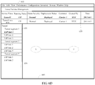
- FIG. 6B includes a service management list 630 and the menu option 605.
- the service management list 630 includes two parameters: a "Tunnel 1" parameter 631 (indicating a forward tunnel link) and a "Tunnel 1-reverse” parameter 635 (indicating a reverse tunnel link).
- the interface shown in FIG. 6C is presented by selecting the "Tunnel 1" parameter 631 in the service management list 630.
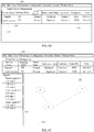
- FIG. 6C includes the service management list 630, a tunnel forward topology view 640, and an LSP link list 650. If the "Tunnel 1-reverse" parameter 635 is selected in the service management list 630, a tunnel reverse topology view is correspondingly presented, which is not repeatedly described herein.
- FIG. 6D presents an LSP link topology view 660.
- An embodiment of the present invention provides a method for presenting a network path, which can improve the working efficiency in the foregoing method.
- FIG. 1 is a flowchart of a method 10 for presenting a network path according to an embodiment of the present invention.
- VPN service data corresponding to VPN service information selected by the first input, where the first input is used for selecting the VPN (Virtual Private Network, virtual private network) service information.
- a plurality of connection relationships of a network path may be presented in a topology view, so that a complex activity of a user's manual query is simplified, and a skill requirement imposed on the user is lowered.
- the user does not need to memorize association relationships of services.
- relationships between layers of paths of the services can be clearly presented in one interface. This facilitates fault locating by the user, thereby improving the working efficiency of the user.
- FIG. 2 is a diagram of interaction of a method 200 for presenting a network path according to another embodiment of the present invention.
- the method 200 may be implemented by a network management apparatus.
- the network management apparatus includes a VPN service list module 201, a VPN first topology module 202, a VPN multi-layer topology module 203, a network management server module 204, and a device management module 205. The following describes interaction processes between these modules in detail.
- the VPN service list module 201 presents VPN service information in a list form, where the list is shown in 610 of FIG. 6 .
- the VPN service list module 201 queries, from the network management server module 204 according to a first input, VPN service data corresponding to the VPN service information selected by the first input.
- the first input may be the VPN service information selected by a user by using a mouse.
- the network management server module 204 sends the queried VPN service data to the VPN first topology module 202.
- the VPN first topology module 202 presents a first topology view according to the VPN service data, where the first topology view presents a service connection relationship between network elements.
- the first topology view is shown in 620 of FIG. 6A .
- the VPN service list module 201 queries, from the network management server module 204, the VPN service data according to a second input for the first topology view.
- the second input used for presenting a second topology view may be received by selecting, by the user, the first topology view and clicking an option in a drop-down menu that is displayed by right-clicking, for example, selecting an option named service path.
- the network management server module 204 sends the queried VPN service data to the VPN multi-layer topology module 203.
- the network management server module 204 sends a service identifier corresponding to the acquired VPN service data to the device management module 205.
- the device management module 205 feeds back a tunnel (tunnel) identifier corresponding to the service identifier to the network management server module 204.
- the network management server module 204 sends the fed-back tunnel data to the VPN multi-layer topology module 203.
- the network management server module 204 sends the tunnel identifier to the device management module 205.
- the device management module 205 sends LSP path data corresponding to the tunnel identifier to the network management server module 204.
- the network management server module 204 sends the fed-back LSP path data to the VPN multi-layer topology module 203.
- the VPN multi-layer topology module 203 presents the second topology view according to the VPN service data, the tunnel data, and the LSP path data, as shown in FIG. 3A .
- the second topology view includes a plurality of different topology layers presenting connection relationships between the network elements.
- the presented second topology view includes the plurality of different topology layers that are three-dimensionally presented and used for presenting the connection relationships between the network elements.
- the three-dimensional presentation manner in an interface is more visual than the presentation of a plurality of connection relationships within a plane, which further facilitates fault locating by the user.
- the plurality of topology layers include a first topology layer (a VPN layer) corresponding to the VPN service data, a second topology layer (a tunnel layer) corresponding to the tunnel data, and a third topology layer (an LSP layer) corresponding to the LSP path data respectively.
- the first topology layer is generated according to the VPN service data, and the first topology layer is used for presenting a service connection relationship between the network elements 310 and 311.
- the second topology layer is generated according to the tunnel data, and the second topology layer is used for presenting a tunnel connection relationship between the network elements 310 and 311.
- the third topology layer is generated according to the LSP path data, and the third topology layer is used for presenting an LSP connection relationship between the network elements 310 and 311.
- the first topology layer is shown in 301 of FIG. 3 .
- the second topology layer is shown in 302 of FIG. 3 , where the network element 310 is connected to the network element 311 by using a network element 312.
- the third topology layer is shown in 303 of FIG. 3 , where the network element 310 is connected to the network element 311 by using network elements 313, 312, and 314.
- the third topology layer completely presents a physical path instead of displaying the physical path segment by segment, which greatly facilitates the user's clear understanding of the network.
- the VPN multi-layer topology module 203 presents, in a highlighting manner, a target object selected at the topology layers and a topology layer in which the selected target object is located. As shown in FIG. 3B , the network element 310 is presented in a highlighting manner by means of boldface.
- highlighted display is implemented by means of boldface in the drawings of the embodiments of the present invention, highlighted display may also be implemented in other manners.
- highlighted display is implemented by changing the line widths of the selected target object and the topology layer in which the selected target object is located, setting the lines to solid lines or dashed lines, and setting whether the lines flicker.
- the view angle of the topology layer in which the target object is located may also be adjusted so that the user views and adjusts the target object at the topology layer, as shown in 303 of FIG. 3C .
- the VPN multi-layer topology module 203 is used for presenting, next to the selected topology layer, a shortcut toolbar for adjusting the topology layer, as shown in 320 of FIG. 3C .
- the shortcut toolbar may include options for adjusting the topology layer, such as zoom in, zoom out, find, capture, fit to screen, and bird's-eye viewtopology layer.
- the VPN multi-layer topology module 203 presents a topology layer that is adjusted to adapt to the change, as shown in FIG. 3D .
- the second topology layer 302 and the third topology layer 303 are accordingly adjusted separately according to the tunnel data and the LSP path data re-queried by the network management server module 204 and the device management module 205.
- the network element 310 is connected to the network element 330 by using the network element 331.
- the network element 310 is connected to the network element 330 by using network elements 332, 333, 331, and 334.
- the VPN multi-layer topology module 203 presents a topology layer that is adjusted to adapt to the change, as shown in FIG. 3E .
- the user originally views a forward tunnel, as shown in the second topology layer 302 of FIG. 3B , and in this case, the forward tunnel is changed into a reverse tunnel, as shown in the second topology layer 302 of FIG. 3E .
- the path at the LSP layer needs to be re-queried by using the network management server module 204 and the device management module 205, and presented at the third topology layer 303.
- the network element 311 is connected to the network element 310 by using network elements 316, 312, and 315.
- a plurality of connection relationships of a network path may be presented in a topology view, so that a complex activity of a user's manual query is simplified, and a skill requirement imposed on the user is lowered.
- the user does not need to memorize association relationships of services.
- relationships between layers of paths of the services can be clearly presented in one interface. This facilitates fault locating by the user, thereby improving the working efficiency of the user.
- FIG. 4 is a block diagram of an apparatus 40 for presenting a network path according to an embodiment of the present invention.
- the apparatus 40 includes a first querying module 41, a first presenting module 42, and a second presenting module 43.
- the first querying module 41 queries, according to a first input, VPN service data corresponding to VPN service information selected by the first input, where the first input is used for selecting the VPN (Visual Private Network, virtual private network) service information.
- VPN Virtual Private Network, virtual private network
- the first presenting module 42 presents a first topology view according to the VPN service data queried by the first querying module 41, where the first topology view presents a service connection relationship between network elements.
- the second presenting module 43 presents a second topology view according to a second input for the first topology view presented by the first presenting module 42, where the second input is used for presenting the second topology view and the presented second topology view includes a plurality of different topology layers presenting connection relationships between the network elements.
- the apparatus 40 implements the method 10. The details are not repeatedly described herein.
- a plurality of connection relationships of a network path may be presented in a topology view, so that a complex activity of a user's manual query is simplified, and a skill requirement imposed on the user is lowered.
- the user does not need to memorize association relationships of services.
- relationships between layers of paths of the services can be clearly presented in one interface. This facilitates fault locating by the user, thereby improving the working efficiency of the user.
- FIG. 5 is a block diagram of another apparatus 50 for presenting a network path according to an embodiment of the present invention.
- the apparatus 50 includes a first querying module 51, a first presenting module 52, and a second presenting module 53, which are the same as or similar to the first querying module 41, the first presenting module 42, and the second presenting 43 of the apparatus 40.
- the first querying module 51 queries, according to a first input, VPN service data corresponding to VPN service information selected by the first input, where the first input is used for selecting the VPN (Visual Private Network, virtual private network) service information.
- VPN Virtual Private Network, virtual private network
- the first presenting module 52 presents a first topology view according to the VPN service data queried by the first querying module 51, where the first topology view presents a service connection relationship between network elements.
- the second presenting module 53 presents a second topology view according to a second input for the first topology view presented by the first presenting module 52, where the second input is used for presenting the second topology view and the presented second topology view includes a plurality of different topology layers presenting connection relationships between the network elements.
- the presented second topology view may include the plurality of different topology layers that are three-dimensionally presented and used for presenting the connection relationships between the network elements.
- the three-dimensional presentation manner in an interface is more visual than the presentation of a plurality of connection relationships within a plane, which further facilitates fault locating by a user.
- the apparatus 50 further includes a second querying module 54 and a list presenting module 55.
- the second querying module 54 separately acquires the VPN service data, a tunnel data, and a LSP path data according to the second input for the first topology view presented by the first presenting module 52, and sends the queried data to the second presenting module 53.
- the presenting, by a second presenting module, a second topology view, where the second topology view includes a plurality of different topology layers presenting connection relationships between the network elements specifically includes:
- the list presenting module 55 presents the VPN service information in a list form.
- the network management apparatus in the method 200 may serve as an implementation manner for the apparatus 50.
- the network management server module 204 and the device management module 205 may implement the second querying module 54.
- the VPN service list module 201 may implement the list presenting module 55 and the first querying module 51.
- the VPN first topological module 202 may implement the first presenting module 52.
- the VPN multi-layer topology module 203 may implement the second presenting module 53.
- the apparatus 50 implements the methods 10 and 200. The details are not repeatedly described herein.
- a plurality of connection relationships of a network path may be presented in a topology view, so that a complex activity of a user's manual query is simplified, and a skill requirement imposed on the user is lowered.
- the user does not need to memorize association relationships of services.
- relationships between layers of paths of the services can be clearly presented in one interface. This facilitates fault locating by the user, thereby improving the working efficiency of the user.
- the plurality of topology layers presented by the second presenting module 53 include a first topology layer corresponding to the VPN service data, a second topology layer corresponding to the tunnel data, and a third topology layer corresponding to the LSP path data.
- the first topology layer is used for presenting a service connection relationship between the network elements;
- the second topology layer is used for presenting a Tunnel connection relationship between the network elements;
- the third topology layer is used for presenting an LSP connection relationship between the network elements.
- the second presenting module 53 may further present, in a highlighting manner and according to a third input, a target object selected at the topology layers, and a topology layer in which the selected target object is located.
- the second presenting module 53 may further present, next to the selected topology layer and according to a fourth input, a shortcut toolbar for adjusting the topology layer.
- the second presenting module 53 may further present, when changing, according to a fifth input, the target object selected at the first topology layer, a topology layer that is adjusted to adapt to the change.
- the second presenting module 53 may further present, when changing, according to a sixth input, the target object selected at the second topology layer, a topology layer that is adjusted to adapt to the change.
- a plurality of connection relationships of a network path may be presented in a topology view, so that a complex activity of a user's manual query is simplified, and a skill requirement imposed on the user is lowered.
- the user does not need to memorize association relationships of services.
- relationships between layers of paths of the services can be clearly presented in one interface. This facilitates fault locating by the user, thereby improving the working efficiency of the user.
- the disclosed system, apparatus, and method may be implemented in other manners.
- the described apparatus embodiment is merely exemplary.
- the unit division is merely logical function division and may be other division in actual implementation.
- a plurality of units or components may be combined or integrated into another system, or some features may be ignored or not performed.
- the displayed or discussed mutual couplings or direct couplings or communication connections may be implemented through some interfaces.
- the indirect couplings or communication connections between the apparatuses or units may be implemented in electronic, mechanical, or other forms.
- the units described as separate parts may or may not be physically separate, and parts displayed as units may or may not be physical units, may be located in one position, or may be distributed on a plurality of network units. A part or all of the units may be selected according to actual needs to achieve the objectives of the solutions of the embodiments.
- functional units in the embodiments of the present invention may be integrated into one processing unit, or each of the units may exist alone physically, or two or more units are integrated into one unit.
- the functions When the functions are implemented in a form of a software functional unit and sold or used as an independent product, the functions may be stored in a computer-readable storage medium. Based on such an understanding, the technical solutions of the present invention essentially, or the part contributing to the prior art, or a part of the technical solutions may be implemented in a form of a software product.
- the software product is stored in a storage medium, and includes several instructions for instructing a computer device (which may be a personal computer, a server, or a network device) to perform all or a part of the steps of the methods described in the embodiments of the present invention.
- the foregoing storage medium includes: any medium that can store program code, such as a USB flash drive, a removable hard disk, a read-only memory (Read-Only Memory, ROM), a random access memory (Random Access Memory, RAM), a magnetic disk, or an optical disc.
- program code such as a USB flash drive, a removable hard disk, a read-only memory (Read-Only Memory, ROM), a random access memory (Random Access Memory, RAM), a magnetic disk, or an optical disc.
Description
- The present invention relates to the Internet Protocol (IP, Internet Protocol) field, and in particular, to a method and an apparatus for presenting a network path.
- With development of communications services, a network size is becoming larger, and network visualized operation and maintenance (O&M, Operation and Maintenance) becomes a main trend in user operation and maintenance. However, at present, regardless of which network operation and maintenance software is used, information acquired by a user from a topology view, of a network management system, for routine operation and maintenance is limited. The topology view presents various paths corresponding to an association relationship. For example, by means of one operation, only a service connection relationship between network elements can be viewed, but routing of a path that carries a service cannot be viewed, for example, an LSP (Label Switch Path, label switched path) connection relationship; or only the LSP connection relationship can be viewed, but the service connection relationship cannot be viewed. Consequently, a great difficulty is caused to a user's clear understanding of a network, and the user fails to have a visual learning of the network. Therefore, the user's working efficiency is low in multiple repeated operations.
- Chapter 64 titled "Using the Topology Tool" of the "Cisco Prime Fulfillment User Guide 6.1" of Cisco Inc., describes a Topology Tool, which provides a graphical view of networks. There are three view panes in a Topology Application, a VPN View, a Logical View and a Physical View. An Aggregate View, as shown in Figure 64-7, shows connectivity between all customer devices, regardless of the type of technology used to connect them.
- Document
US 2002/135610 A1 discloses a method to display a multilayer topology using XML and HTML markup language. The multi-layer topology visualisation is demonstrated for a network topology comprising an area layer topology, physical layer and an IP layer and also demonstrated for a electronic circuit topology. - Chapter 17 titled "Monitoring MPLS Services" of the "Cisco Prime Network 3.8 User Guide" of Cisco Inc., discloses that Prime Network Vision automatically discovers MPLS-TP tunnels, endpoints, and midpoints and enables a user to add MLPS-TP tunnels to maps using a dialog box. On completion of the dialog box, the MPLS-TP tunnel is added to a displayed map and to a navigation pane.
- The invention concerns a method according to
claim 1 and an apparatus according to claim 7. - According to one aspect, a method for presenting a network path is provided, including: querying, according to a first input, VPN service data corresponding to VPN service information selected by the first input, where the first input is used for selecting the VPN service information; presenting a first topology view according to the VPN service data, where the first topology view presents a service connection relationship between first network elements; and presenting a second topology view according to a second input for the first topology view, where the presented second topology view includes a plurality of different topology layers presenting connection relationships between the first network elements. Therein the plurality of topology layers comprised in the second topology view comprises a first topology layer corresponding to the VPN service data, a second topology layer corresponding to tunnel data, and a third topology layer corresponding to label switched path, LSP, data; wherein the first topology layer is used for presenting the service connection relationship between the first network elements, the second topology layer is used for presenting a tunnel connection relationship between the first network elements, and the third topology layer is used for presenting an LSP connection relationship between the first network elements. Before the presenting a second topology view, the method further comprises separately acquiring the VPN service data, the tunnel data, and the LSP path data according to the second input. Correspondingly, the presenting a second topology view, wherein the second topology view comprises a plurality of different topology layers presenting connection relationships between the first network elements, specifically comprises: generating, according to the VPN service data, the first topology layer used for presenting the service connection relationship between the first network elements; generating, according to the tunnel data, the second topology layer used for presenting the tunnel connection relationship between the first network elements, wherein a first path comprising second network elements at the second topology layer is automatically associated with the service connection relationship between the first network elements of the first topology layer; and generating, according to the LSP path
data, the third topology layer used for presenting the LSP connection relationship between the first network elements, wherein a second path comprising third network elements at the third topology layer is automatically associated with the service connection relationship between the first network elements of the first topology layer. - According to another aspect, an apparatus for presenting a network path is provided, including: a first querying module, configured to query, according to a first input, VPN service data corresponding to VPN service information selected by the first input, where the first input is used for selecting the VPN service information; a first presenting module, configured to present a first topology view according to the VPN service data acquired by the first querying module, where the first topology view presents a service connection relationship between first network elements; and a second presenting module, configured to present a second topology view according to a second input for the first topology view presented by the first presenting module, where the second input is used for presenting the second topology view and the presented second topology view includes a plurality of different topology layers presenting connection relationships between the first network elements. The plurality of topology layers comprised in the second topology view presented by the second presenting module separately comprises a first topology layer corresponding to the VPN service data, a second topology layer corresponding to tunnel data, and a third topology layer corresponding to LSP path data; wherein the first topology layer is used for presenting the service connection relationship between the first network elements, the second topology layer is used for presenting a tunnel connection relationship between the first network elements, and the third topology layer is used for presenting an LSP connection relationship between the first network elements. The apparatus further comprises a second querying module, configured to separately acquire the VPN service data, the tunnel data, and the LSP path data according to the second input, and send the acquired data to the second presenting module. Correspondingly, the presenting, by the second presenting module, a second topology view, wherein the second topology view comprises a plurality of different topology layers presenting connection relationships between the first network elements, specifically comprises generating, by the second presenting module according to the VPN service data, the first topology layer used for presenting the service connection relationship between the first network elements; generating, by the second presenting module according to the tunnel data, the second topology layer used for presenting the Tunnel connection relationship between the first network elements, wherein a first path comprising second network elements at the second topology layer is automatically associated with the service connection relationship between the first network elements of the first topology layer; and generating, by the second presenting module according to the LSP path
- data, the third topology layer used for presenting the LSP connection relationship between the first network elements, wherein a second path comprising third network elements at the third topology layer is automatically associated with the service connection relationship between the first network elements of the first topology layer.
- By using the foregoing solutions, a plurality of connection relationships of a network path may be presented in a topology view, so that a complex activity of a user's manual query is simplified, and a skill requirement imposed on the user is lowered. In this way, the user does not need to memorize association relationships of services. In addition, during viewing of the associated paths of the services, relationships between layers of paths of the services can be clearly presented in one interface. This facilitates fault locating by the user, thereby improving the working efficiency of the user.
-
-
FIG. 1 is a flowchart of a method for presenting a network path according to an embodiment of the present invention; -
FIG. 2 is a flowchart of a method for presenting a network path according to another embodiment of the present invention; -
FIG. 3A to FIG. 3E are schematic diagrams of a method for presenting a network path according to an embodiment of the present invention; -
FIG. 4 is a block diagram of an apparatus for presenting a network path according to an embodiment of the present invention; -
FIG. 5 is a block diagram of another apparatus for presenting a network path according to an embodiment of the present invention; and -
FIG. 6A to FIG. 6D are schematic diagrams of related methods for presenting a network path. - The following clearly and completely describes the technical solutions in the embodiments of the present invention with reference to the accompanying drawings in the embodiments of the present invention. Apparently, the described embodiments are a part rather than all of the embodiments of the present invention. All other embodiments obtained by a person of ordinary skill in the art based on the embodiments of the present invention without creative efforts shall fall within the protection scope of the present invention.
- In network management software, a user can view only one type of network topology at a time; after a certain object is concerned in a network topology, the concerned information can be viewed by searching another related network topology for the object or by using a redirection portal that is provided. The user must manually establish an association relationship between the two topologies.
- The current user's operations of viewing layers of paths include: viewing a VPN path, redirecting to view a tunnel path, and separately viewing each segmented LSP path in the tunnel path.
FIG. 6A to FIG. 6C illustrate related methods for presenting a network path by using an example that a path of an L3VPN service is viewed. -
FIG. 6A presents an interface displayed after a "service 1" parameter in a specified L3VPN is selected, including aVPN service list 610, afirst topology view 620, and amenu option 605. Herein, the bold italic type is used for highlighted display. - A VPN service path between a network element A and a network element B is selected in the
first topology view 620, a menu is displayed by right-clicking, a "View Tunnel" option is selected, and subsequently the interface shown inFIG. 6B is presented. -
FIG. 6B includes aservice management list 630 and themenu option 605. Theservice management list 630 includes two parameters: a "Tunnel 1" parameter 631 (indicating a forward tunnel link) and a "Tunnel 1-reverse" parameter 635 (indicating a reverse tunnel link). - The interface shown in
FIG. 6C is presented by selecting the "Tunnel 1"parameter 631 in theservice management list 630. -
FIG. 6C includes theservice management list 630, a tunnelforward topology view 640, and anLSP link list 650. If the "Tunnel 1-reverse"parameter 635 is selected in theservice management list 630, a tunnel reverse topology view is correspondingly presented, which is not repeatedly described herein. - Subsequently, a forward LSP link of the
tunnel 1 can be viewed segment by segment only by selecting parameters in theLSP link list 650 one by one. After an "LSP link 1"parameter 651 is selected,FIG. 6D presents an LSPlink topology view 660. - In the foregoing method, the user needs to understand an association relationship between a VPN service link, a tunnel link, and an LSP link, and manually record the relationship between the three links during a searching process, which is inefficient. An embodiment of the present invention provides a method for presenting a network path, which can improve the working efficiency in the foregoing method.
-
FIG. 1 is a flowchart of amethod 10 for presenting a network path according to an embodiment of the present invention. - 11. Query, according to a first input, VPN service data corresponding to VPN service information selected by the first input, where the first input is used for selecting the VPN (Virtual Private Network, virtual private network) service information.
- 13. Present a first topology view according to the VPN service data, where the first topology view presents a service connection relationship between network elements.
- 15. Present a second topology view according to a second input for the first topology view, where the presented second topology view includes a plurality of different topology layers presenting connection relationships between the network elements.
- According to this embodiment of the present invention, a plurality of connection relationships of a network path may be presented in a topology view, so that a complex activity of a user's manual query is simplified, and a skill requirement imposed on the user is lowered. In this way, the user does not need to memorize association relationships of services. In addition, during viewing of the associated paths of the services, relationships between layers of paths of the services can be clearly presented in one interface. This facilitates fault locating by the user, thereby improving the working efficiency of the user.
-
FIG. 2 is a diagram of interaction of amethod 200 for presenting a network path according to another embodiment of the present invention. - The
method 200 may be implemented by a network management apparatus. The network management apparatus includes a VPNservice list module 201, a VPNfirst topology module 202, a VPNmulti-layer topology module 203, a networkmanagement server module 204, and adevice management module 205. The following describes interaction processes between these modules in detail. - 210. First, the VPN
service list module 201 presents VPN service information in a list form, where the list is shown in 610 ofFIG. 6 . - 215. The VPN
service list module 201 queries, from the networkmanagement server module 204 according to a first input, VPN service data corresponding to the VPN service information selected by the first input. - The first input may be the VPN service information selected by a user by using a mouse.
- 220. The network
management server module 204 sends the queried VPN service data to the VPNfirst topology module 202. - 225. The VPN
first topology module 202 presents a first topology view according to the VPN service data, where the first topology view presents a service connection relationship between network elements. The first topology view is shown in 620 ofFIG. 6A . - 230. The VPN
service list module 201 queries, from the networkmanagement server module 204, the VPN service data according to a second input for the first topology view. - The second input used for presenting a second topology view may be received by selecting, by the user, the first topology view and clicking an option in a drop-down menu that is displayed by right-clicking, for example, selecting an option named service path.
- 235. The network
management server module 204 sends the queried VPN service data to the VPNmulti-layer topology module 203. - 240. The network
management server module 204 sends a service identifier corresponding to the acquired VPN service data to thedevice management module 205. - 245. The
device management module 205 feeds back a tunnel (tunnel) identifier corresponding to the service identifier to the networkmanagement server module 204. - 250. The network
management server module 204 sends the fed-back tunnel data to the VPNmulti-layer topology module 203. - 255. The network
management server module 204 sends the tunnel identifier to thedevice management module 205. - 260. The
device management module 205 sends LSP path data corresponding to the tunnel identifier to the networkmanagement server module 204. - 265. The network
management server module 204 sends the fed-back LSP path data to the VPNmulti-layer topology module 203. - 270. The VPN
multi-layer topology module 203 presents the second topology view according to the VPN service data, the tunnel data, and the LSP path data, as shown inFIG. 3A . - The second topology view includes a plurality of different topology layers presenting connection relationships between the network elements. The presented second topology view includes the plurality of different topology layers that are three-dimensionally presented and used for presenting the connection relationships between the network elements. In this embodiment of the present invention, the three-dimensional presentation manner in an interface is more visual than the presentation of a plurality of connection relationships within a plane, which further facilitates fault locating by the user.
- The plurality of topology layers include a first topology layer (a VPN layer) corresponding to the VPN service data, a second topology layer (a tunnel layer) corresponding to the tunnel data, and a third topology layer (an LSP layer) corresponding to the LSP path data respectively. The first topology layer is generated according to the VPN service data, and the first topology layer is used for presenting a service connection relationship between the
network elements network elements network elements FIG. 3 . The second topology layer is shown in 302 ofFIG. 3 , where thenetwork element 310 is connected to thenetwork element 311 by using anetwork element 312. The third topology layer is shown in 303 ofFIG. 3 , where thenetwork element 310 is connected to thenetwork element 311 by usingnetwork elements - In this way, paths at the tunnel layer and the LSP layer are automatically associated according to top layer service information. Accordingly, the user may not have basic knowledge about IP layering, and does not need to manually establish the association relationship and manually query service data. In addition, the third topology layer completely presents a physical path instead of displaying the physical path segment by segment, which greatly facilitates the user's clear understanding of the network.
- 275. According to a third input, the VPN
multi-layer topology module 203 presents, in a highlighting manner, a target object selected at the topology layers and a topology layer in which the selected target object is located. As shown inFIG. 3B , thenetwork element 310 is presented in a highlighting manner by means of boldface. - Although highlighted display is implemented by means of boldface in the drawings of the embodiments of the present invention, highlighted display may also be implemented in other manners. For example, highlighted display is implemented by changing the line widths of the selected target object and the topology layer in which the selected target object is located, setting the lines to solid lines or dashed lines, and setting whether the lines flicker. In addition, the view angle of the topology layer in which the target object is located may also be adjusted so that the user views and adjusts the target object at the topology layer, as shown in 303 of
FIG. 3C . - 280. According to a fourth input, the VPN
multi-layer topology module 203 is used for presenting, next to the selected topology layer, a shortcut toolbar for adjusting the topology layer, as shown in 320 ofFIG. 3C . - The shortcut toolbar may include options for adjusting the topology layer, such as zoom in, zoom out, find, capture, fit to screen, and bird's-eye viewtopology layer.
- 285. When changing, according to a fifth input, the target object selected at the first topology layer, the VPN
multi-layer topology module 203 presents a topology layer that is adjusted to adapt to the change, as shown inFIG. 3D . - For example, if the service information between the
network elements network elements first topology layer 301 ofFIG. 3D , thesecond topology layer 302 and thethird topology layer 303 are accordingly adjusted separately according to the tunnel data and the LSP path data re-queried by the networkmanagement server module 204 and thedevice management module 205. As shown in 302 ofFIG. 3D , thenetwork element 310 is connected to thenetwork element 330 by using thenetwork element 331. As shown in 303 ofFIG. 3D , thenetwork element 310 is connected to thenetwork element 330 by usingnetwork elements - 290. When changing, according to a sixth input, the target object selected at the second topology layer, the VPN
multi-layer topology module 203 presents a topology layer that is adjusted to adapt to the change, as shown inFIG. 3E . - For example, the user originally views a forward tunnel, as shown in the
second topology layer 302 ofFIG. 3B , and in this case, the forward tunnel is changed into a reverse tunnel, as shown in thesecond topology layer 302 ofFIG. 3E . The path at the LSP layer needs to be re-queried by using the networkmanagement server module 204 and thedevice management module 205, and presented at thethird topology layer 303. As shown inFIG. 3E , thenetwork element 311 is connected to thenetwork element 310 by usingnetwork elements - According to this embodiment of the present invention, a plurality of connection relationships of a network path may be presented in a topology view, so that a complex activity of a user's manual query is simplified, and a skill requirement imposed on the user is lowered. In this way, the user does not need to memorize association relationships of services. In addition, during viewing of the associated paths of the services, relationships between layers of paths of the services can be clearly presented in one interface. This facilitates fault locating by the user, thereby improving the working efficiency of the user.
-
FIG. 4 is a block diagram of anapparatus 40 for presenting a network path according to an embodiment of the present invention. - The
apparatus 40 includes afirst querying module 41, afirst presenting module 42, and asecond presenting module 43. - The
first querying module 41 queries, according to a first input, VPN service data corresponding to VPN service information selected by the first input, where the first input is used for selecting the VPN (Visual Private Network, virtual private network) service information. - The
first presenting module 42 presents a first topology view according to the VPN service data queried by thefirst querying module 41, where the first topology view presents a service connection relationship between network elements. - The
second presenting module 43 presents a second topology view according to a second input for the first topology view presented by thefirst presenting module 42, where the second input is used for presenting the second topology view and the presented second topology view includes a plurality of different topology layers presenting connection relationships between the network elements. - The
apparatus 40 implements themethod 10. The details are not repeatedly described herein. - According to this embodiment of the present invention, a plurality of connection relationships of a network path may be presented in a topology view, so that a complex activity of a user's manual query is simplified, and a skill requirement imposed on the user is lowered. In this way, the user does not need to memorize association relationships of services. In addition, during viewing of the associated paths of the services, relationships between layers of paths of the services can be clearly presented in one interface. This facilitates fault locating by the user, thereby improving the working efficiency of the user.
-
FIG. 5 is a block diagram of anotherapparatus 50 for presenting a network path according to an embodiment of the present invention. - The
apparatus 50 includes afirst querying module 51, afirst presenting module 52, and asecond presenting module 53, which are the same as or similar to thefirst querying module 41, thefirst presenting module 42, and the second presenting 43 of theapparatus 40. - The
first querying module 51 queries, according to a first input, VPN service data corresponding to VPN service information selected by the first input, where the first input is used for selecting the VPN (Visual Private Network, virtual private network) service information. - The
first presenting module 52 presents a first topology view according to the VPN service data queried by thefirst querying module 51, where the first topology view presents a service connection relationship between network elements. - The
second presenting module 53 presents a second topology view according to a second input for the first topology view presented by thefirst presenting module 52, where the second input is used for presenting the second topology view and the presented second topology view includes a plurality of different topology layers presenting connection relationships between the network elements. The presented second topology view may include the plurality of different topology layers that are three-dimensionally presented and used for presenting the connection relationships between the network elements. In this embodiment of the present invention, the three-dimensional presentation manner in an interface is more visual than the presentation of a plurality of connection relationships within a plane, which further facilitates fault locating by a user. - Different from the
apparatus 40, theapparatus 50 further includes asecond querying module 54 and alist presenting module 55. - The
second querying module 54 separately acquires the VPN service data, a tunnel data, and a LSP path data according to the second input for the first topology view presented by thefirst presenting module 52, and sends the queried data to thesecond presenting module 53. - The presenting, by a second presenting module, a second topology view, where the second topology view includes a plurality of different topology layers presenting connection relationships between the network elements, specifically includes:
- generating, by the second presenting module and according to the VPN service data, the first topology layer used for presenting the service connection relationship between the network elements;
- generating, by the second presenting module and according to the tunnel data, the second topology layer used for presenting the Tunnel connection relationship between the network elements; and
- generating, by the second presenting module and according to the LSP path data, the third topology layer used for presenting the LSP connection relationship between the network elements.
- The
list presenting module 55 presents the VPN service information in a list form. - The network management apparatus in the
method 200 may serve as an implementation manner for theapparatus 50. The networkmanagement server module 204 and thedevice management module 205 may implement thesecond querying module 54. The VPNservice list module 201 may implement thelist presenting module 55 and thefirst querying module 51. The VPN firsttopological module 202 may implement thefirst presenting module 52. The VPNmulti-layer topology module 203 may implement thesecond presenting module 53. - The
apparatus 50 implements themethods - According to this embodiment of the present invention, a plurality of connection relationships of a network path may be presented in a topology view, so that a complex activity of a user's manual query is simplified, and a skill requirement imposed on the user is lowered. In this way, the user does not need to memorize association relationships of services. In addition, during viewing of the associated paths of the services, relationships between layers of paths of the services can be clearly presented in one interface. This facilitates fault locating by the user, thereby improving the working efficiency of the user.
- The plurality of topology layers presented by the
second presenting module 53 include a first topology layer corresponding to the VPN service data, a second topology layer corresponding to the tunnel data, and a third topology layer corresponding to the LSP path data. The first topology layer is used for presenting a service connection relationship between the network elements; the second topology layer is used for presenting a Tunnel connection relationship between the network elements; and the third topology layer is used for presenting an LSP connection relationship between the network elements. - In addition, the
second presenting module 53 may further present, in a highlighting manner and according to a third input, a target object selected at the topology layers, and a topology layer in which the selected target object is located. - The
second presenting module 53 may further present, next to the selected topology layer and according to a fourth input, a shortcut toolbar for adjusting the topology layer. - The
second presenting module 53 may further present, when changing, according to a fifth input, the target object selected at the first topology layer, a topology layer that is adjusted to adapt to the change. - The
second presenting module 53 may further present, when changing, according to a sixth input, the target object selected at the second topology layer, a topology layer that is adjusted to adapt to the change. - According to this embodiment of the present invention, a plurality of connection relationships of a network path may be presented in a topology view, so that a complex activity of a user's manual query is simplified, and a skill requirement imposed on the user is lowered. In this way, the user does not need to memorize association relationships of services. In addition, during viewing of the associated paths of the services, relationships between layers of paths of the services can be clearly presented in one interface. This facilitates fault locating by the user, thereby improving the working efficiency of the user.
- A person of ordinary skill in the art may be aware that, in combination with the examples described in the embodiments disclosed in this specification, units and algorithm steps may be implemented by electronic hardware or a combination of computer software and electronic hardware. Whether the functions are performed by hardware or software depends on particular applications and design constraint conditions of the technical solutions. A person skilled in the art may use different methods to implement the described functions for each particular application, but it should not be considered that the implementation goes beyond the scope of the present invention.
- It may be clearly understood by a person skilled in the art that, for the purpose of convenient and brief description, for a detailed working process of the foregoing system, apparatus, and unit, reference may be made to a corresponding process in the foregoing method embodiments, and details are not described herein again.
- In the several embodiments provided in the present application, it should be understood that the disclosed system, apparatus, and method may be implemented in other manners. For example, the described apparatus embodiment is merely exemplary. For example, the unit division is merely logical function division and may be other division in actual implementation. For example, a plurality of units or components may be combined or integrated into another system, or some features may be ignored or not performed. In addition, the displayed or discussed mutual couplings or direct couplings or communication connections may be implemented through some interfaces. The indirect couplings or communication connections between the apparatuses or units may be implemented in electronic, mechanical, or other forms.
- The units described as separate parts may or may not be physically separate, and parts displayed as units may or may not be physical units, may be located in one position, or may be distributed on a plurality of network units. A part or all of the units may be selected according to actual needs to achieve the objectives of the solutions of the embodiments.
- In addition, functional units in the embodiments of the present invention may be integrated into one processing unit, or each of the units may exist alone physically, or two or more units are integrated into one unit.
- When the functions are implemented in a form of a software functional unit and sold or used as an independent product, the functions may be stored in a computer-readable storage medium. Based on such an understanding, the technical solutions of the present invention essentially, or the part contributing to the prior art, or a part of the technical solutions may be implemented in a form of a software product. The software product is stored in a storage medium, and includes several instructions for instructing a computer device (which may be a personal computer, a server, or a network device) to perform all or a part of the steps of the methods described in the embodiments of the present invention. The foregoing storage medium includes: any medium that can store program code, such as a USB flash drive, a removable hard disk, a read-only memory (Read-Only Memory, ROM), a random access memory (Random Access Memory, RAM), a magnetic disk, or an optical disc.
- The foregoing descriptions are merely specific embodiments of the present invention, but are not intended to limit the protection scope of the present invention. Any variation or replacement readily figured out by a person skilled in the art within the technical scope disclosed in the present invention shall fall within the protection scope of the present invention. Therefore, the protection scope of the present invention shall be subject to the protection scope of the claims.
Claims (11)
- A method for presenting a network path, comprising:querying a network management server module (215), according to a first input, virtual private network, VPN, service data corresponding to VPN service information selected by the first input, wherein the first input is used for selecting the VPN service information;receiving from the network management server module (220), the queried VPN service data;presenting a first topology view (225) according to the VPN service data, wherein the first topology view presents a service connection relationship between first network elements (310, 311);querying the network management server module (230), according to a second input for the first topology view;receiving from the network management server module, VPN service data (235), tunnel data (250), and Label Switched Path, LSP, path data (265);wherein the network management server module separately acquires the tunnel data (245) and the LSP path data (260) from a device management module according to the second input;presenting a second topology view (270), according to the second input for the first topology view, wherein the second topology view comprises a plurality of different topology layers presenting connection relationships between the first network elements (310, 311), wherein the plurality of topology layers comprised in the second topology view comprises a first topology layer (301) corresponding to the VPN service data, a second topology layer (302) corresponding to the tunnel data, and a third topology layer (303) corresponding to the LSP path data, the method specifically comprises:generating, according to the VPN service data, the first topology layer (301) used for presenting the service connection relationship between the first network elements (310, 311);generating, according to the tunnel data, the second topology layer (302) used for presenting the tunnel connection relationship between the first network elements (310, 311), wherein a first path comprising second network elements (310, 311, 312) at the second topology layer (302) is automatically associated with the service connection relationship between the first network elements (310, 311) of the first topology layer (301) wherein the first network elements (310, 311) is a subset of the second network elements (310, 311, 312); andgenerating, according to the LSP path data, the third topology layer (303) used for presenting the LSP connection relationship between the first network elements (310, 311), wherein a second path comprising third network elements (310, 311, 312, 313, 314) at the third topology layer (303) is automatically associated with the service connection relationship between the first network elements (310, 311) of the first topology layer (301) wherein the first network elements (310, 311) is a subset of the third network elements (310, 311, 312, 313, 314).
- The method according to claim 1, wherein before the querying, according to the first input, VPN service data corresponding to VPN service information selected by the first input, the method further comprises:
presenting the VPN service information in a list form. - The method according to claim 1 or 2, wherein the method further comprises:
presenting, in a highlighting manner and according to a third input, a target object selected at the topology layers, and a topology layer in which the selected target object is located. - The method according to claim 1 or 2, wherein the method further comprises:
presenting, next to a selected topology layer and according to a fourth input, a shortcut toolbar for adjusting the topology layer. - The method according to claim 1 or 2, wherein the method further comprises:when changing, according to a fifth input, a target object selected at the first topology layer (301), presenting a topology layer that is adjusted to adapt to the change; orwhen changing, according to a sixth input, a target object selected at the second topology layer (302), presenting a topology layer that is adjusted to adapt to the change.
- The method according to any one of claims 1 to 5, wherein the presented second topology view comprises a plurality of different topology layers presenting connection relationships between the first network elements (310, 311) comprises:
the presented second topology view comprises the plurality of different topology layers that are three-dimensionally presented and used for presenting the connection relationships between the first network elements (310, 311). - An apparatus (50) for presenting a network path, comprising:a network management server module (204) and a device management module (205);a first querying module (51), configured to query (215) the network management server module (204), according to a first input, virtual private network, VPN, service data corresponding to VPN service information selected by the first input, wherein the first input is used for selecting the VPN service information and to receive (220) from the network management server module, the queried VPN service data;a first presenting module (52), configured to present a first topology view (225) according to the VPN service data acquired by the first querying module (51), wherein the first topology view presents a service connection relationship between first network elements (310, 311); anda second querying module (54), configured to query (230) the network management server module, according to a second input for the first topology view and to receive from the network management server module, VPN service data (235), tunnel data (250), and Label Switched Path, LSP, path data (265) and send the received data to a second presenting module (53); wherein the network management server module separately acquires the tunnel data (245) and the LSP path data (260) from the device management module (205) according to the second input;the second presenting module (53), configured to present a second topology view (270) according to the second input for the first topology view presented by the first presenting module (52), wherein the second input is used for presenting the second topology view and the presented second topology view comprises a plurality of different topology layers presenting connection relationships between the first network elements (310, 311);wherein the plurality of topology layers comprised in the second topology view presented by the second presenting module (53) comprises:a first topology layer (301) corresponding to the VPN service data, a second topology layer (302) corresponding to tunnel data, and a third topology layer (303) corresponding to LSP path data;generating, by the second presenting module (53) according to the VPN service data, the first topology layer (301) used for presenting the service connection relationship between the first network elements (310, 311);generating, by the second presenting module (53) according to the tunnel data, the second topology layer (302) used for presenting the Tunnel connection relationship between the first network elements (310, 311), wherein a first path comprising second network elements (310, 311, 312) at the second topology layer (302) is automatically associated with the service connection relationship between the first network elements (310, 311) of the first topology layer (301);wherein the first network elements (310, 311) is a subset of the second network elements (310, 311, 312); andgenerating, by the second presenting module (53) according to the LSP path data, the third topology layer (303) used for presenting the LSP connection relationship between the first network elements (310, 311), wherein a second path comprising third network elements (310, 311, 312, 313, 314) at the third topology layer (303) is automatically associated with the service connection relationship between the first network elements (310, 311) of the first topology layer (301) wherein the first network elements (310, 311) is a subset of the third network elements (310, 311, 312, 313, 314).
- The apparatus according to claim 7, wherein the apparatus further comprises:
a list presenting module (55), configured to present the VPN service information in a list form. - The apparatus according to claim 7 or 8, wherein:
the second presenting module (53) is further configured to present, in a highlighting manner and according to a third input, a target object selected at the topology layers, and a topology layer in which the selected target object is located. - The apparatus according to claim 7 or 8, wherein:
the second presenting module (53) is further configured to present, next to a selected topology layer and according to a fourth input, a shortcut toolbar for adjusting the topology layer. - The apparatus according to claim 7 or 8, wherein:the second presenting module (53) is further configured to: when changing, according to a fifth input, a target object selected at the first topology layer (301), present a topology layer that is adjusted to adapt to the change; orwhen changing, according to a sixth input, a target object selected at the second topology layer (302), present a topology layer that is adjusted to adapt to the change.
Applications Claiming Priority (2)
| Application Number | Priority Date | Filing Date | Title |
|---|---|---|---|
| CN201210007016.6A CN102571433B (en) | 2012-01-11 | 2012-01-11 | Method and device for showing network paths |
| PCT/CN2012/081423 WO2013104196A1 (en) | 2012-01-11 | 2012-09-14 | Method and apparatus for presenting network path |
Publications (3)
| Publication Number | Publication Date |
|---|---|
| EP2747340A1 EP2747340A1 (en) | 2014-06-25 |
| EP2747340A4 EP2747340A4 (en) | 2014-09-17 |
| EP2747340B1 true EP2747340B1 (en) | 2018-11-07 |
Family
ID=46415959
Family Applications (1)
| Application Number | Title | Priority Date | Filing Date |
|---|---|---|---|
| EP12865246.8A Active EP2747340B1 (en) | 2012-01-11 | 2012-09-14 | Method and apparatus for presenting network path |
Country Status (4)
| Country | Link |
|---|---|
| US (1) | US9210047B2 (en) |
| EP (1) | EP2747340B1 (en) |
| CN (1) | CN102571433B (en) |
| WO (1) | WO2013104196A1 (en) |
Families Citing this family (17)
| Publication number | Priority date | Publication date | Assignee | Title |
|---|---|---|---|---|
| CN102571433B (en) | 2012-01-11 | 2014-07-30 | 华为技术有限公司 | Method and device for showing network paths |
| US8782526B2 (en) | 2012-03-19 | 2014-07-15 | Huawei Technologies Co., Ltd. | Method and device for processing network element object information in 3D topology view |
| CN102638455B (en) * | 2012-03-19 | 2015-03-11 | 华为技术有限公司 | Method and device for processing network element object information in three-dimensional (3D) topology view |
| CN103200025B (en) * | 2013-02-19 | 2016-06-08 | 华为技术有限公司 | A kind of visual method and device representing routing state in Quickly regroup |
| CN103634147A (en) * | 2013-11-28 | 2014-03-12 | 华为技术服务有限公司 | Network topology management method and equipment |
| USD757049S1 (en) * | 2014-12-16 | 2016-05-24 | LeGuard, Inc. | Display screen with graphical user interface |
| USD757050S1 (en) * | 2014-12-16 | 2016-05-24 | LeGuard, Inc. | Display screen with graphical user interface |
| USD757758S1 (en) * | 2014-12-16 | 2016-05-31 | LeGuard, Inc. | Display screen with graphical user interface |
| USD757051S1 (en) * | 2014-12-16 | 2016-05-24 | LeGuard, Inc. | Display screen with graphical user interface |
| CN106357420A (en) * | 2015-07-16 | 2017-01-25 | 中兴通讯股份有限公司 | Network topology display method, network topology display device and network management system |
| CN107547333B (en) | 2016-06-29 | 2020-02-21 | 华为技术有限公司 | Method and apparatus for implementing a combined virtual private network VPN |
| CN110347752B (en) * | 2018-04-11 | 2023-07-11 | 腾讯科技(深圳)有限公司 | Data processing method, device, computer readable storage medium and computer equipment |
| CN110780852A (en) * | 2019-09-25 | 2020-02-11 | 华青融天(北京)软件股份有限公司 | Method, device, equipment and medium for determining data source |
| US20210111962A1 (en) * | 2019-10-14 | 2021-04-15 | Datrium, Inc. | Topographical search |
| CN111309675B (en) * | 2020-01-20 | 2023-09-26 | 北京有竹居网络技术有限公司 | Associated information display method and device, electronic equipment and storage medium |
| CN114553709B (en) * | 2022-04-28 | 2022-08-23 | 恒生电子股份有限公司 | Topological relation display method and related equipment |
| CN114978716B (en) * | 2022-05-25 | 2024-01-26 | 安天科技集团股份有限公司 | Three-dimensional topology display method and device and electronic equipment |
Family Cites Families (40)
| Publication number | Priority date | Publication date | Assignee | Title |
|---|---|---|---|---|
| US4816567A (en) | 1983-04-08 | 1989-03-28 | Genentech, Inc. | Recombinant immunoglobin preparations |
| US7415548B2 (en) | 1991-05-13 | 2008-08-19 | Broadcom Corporation | Communication network having a plurality of bridging nodes which transmits a polling message with backward learning technique to determine communication pathway |
| DE69232639T2 (en) | 1991-10-01 | 2003-02-20 | Norand Corp | LOCAL RADIO FREQUENCY NETWORK |
| US7917145B2 (en) | 1992-11-02 | 2011-03-29 | Broadcom Corporation | Radio frequency local area network |
| US7937312B1 (en) | 1995-04-26 | 2011-05-03 | Ebay Inc. | Facilitating electronic commerce transactions through binding offers |
| US7269034B2 (en) | 1997-01-24 | 2007-09-11 | Synqor, Inc. | High efficiency power converter |
| US6181055B1 (en) | 1998-10-12 | 2001-01-30 | Extreme Devices, Inc. | Multilayer carbon-based field emission electron device for high current density applications |
| US6535490B1 (en) * | 1999-03-04 | 2003-03-18 | 3Com Corporation | High availability spanning tree with rapid reconfiguration with alternate port selection |
| US7105149B1 (en) | 1999-11-29 | 2006-09-12 | The Trustees Of Columbia University In The City Of New York | Isolation of five novel genes coding for new Fc receptors-type melanoma involved in the pathogenesis of lymphoma/myeloma |
| JP2002288229A (en) * | 2001-03-23 | 2002-10-04 | Hitachi Ltd | Display method of multi-level constitution figure information and its system |
| US7047496B2 (en) | 2002-03-20 | 2006-05-16 | Tropic Networks Inc. | Method for visualization of optical network topology |
| IL152824A (en) | 2002-11-13 | 2012-05-31 | Mosaid Technologies Inc | Addressable outlet and a network using same |
| US8122106B2 (en) | 2003-03-06 | 2012-02-21 | Microsoft Corporation | Integrating design, deployment, and management phases for systems |
| CN1474297A (en) | 2003-06-18 | 2004-02-11 | 中国科学院计算技术研究所 | Organization and maintenance method based on GIS for computer network map |
| IL157787A (en) | 2003-09-07 | 2010-12-30 | Mosaid Technologies Inc | Modular outlet for data communications network |
| US7774461B2 (en) * | 2004-02-18 | 2010-08-10 | Fortinet, Inc. | Mechanism for determining a congestion metric for a path in a network |
| CN1780285A (en) | 2004-11-28 | 2006-05-31 | 中兴通讯股份有限公司 | Hierarchical topological network geographic information displaying method |
| ES2388468T3 (en) | 2005-02-16 | 2012-10-15 | Orica Explosives Technology Pty Ltd | Blasting methods and devices with reduced risk of involuntary or illegal use |
| WO2007012223A1 (en) | 2005-07-28 | 2007-02-01 | Zte Corporation | A method for automatically switched optical network hierarchy routing calculating and connection establishing |
| US7623446B1 (en) * | 2005-11-14 | 2009-11-24 | Nortel Networks Limited | MPLS virtual rings |
| US7681130B1 (en) | 2006-03-31 | 2010-03-16 | Emc Corporation | Methods and apparatus for displaying network data |
| CN101079729B (en) * | 2006-05-23 | 2011-04-20 | 华为技术有限公司 | Method for reserving network resource |
| CN100589427C (en) | 2007-02-14 | 2010-02-10 | 中兴通讯股份有限公司 | Automatic protection method of Ethernet |
| EP2122942B1 (en) | 2007-03-01 | 2017-08-30 | Extreme Networks, Inc. | Software control plane for switches and routers |
| CN100473024C (en) | 2007-04-18 | 2009-03-25 | 中兴通讯股份有限公司 | Dynamic multilevel service quality assurance dispatching system and method |
| US7945647B2 (en) * | 2007-12-10 | 2011-05-17 | Oracle America, Inc. | Method and system for creating a virtual network path |
| CN101437304B (en) | 2008-12-17 | 2011-06-01 | 西安交通大学 | Loose virtual cluster division method for power heterogeneous point Ad Hoc network |
| CN101442811B (en) | 2008-12-30 | 2010-07-28 | 重庆大学 | United control method for wireless resource |
| CN101686262B (en) | 2009-05-14 | 2012-07-25 | 南京大学 | Multi-node collaboration based storage method for sensor network |
| CN101582793B (en) * | 2009-06-05 | 2011-03-30 | 东软集团股份有限公司 | Method and device for graphical display of network topology |
| CN102014403B (en) * | 2009-09-07 | 2014-12-10 | 中兴通讯股份有限公司 | Method and system for transmitting network topology information |
| CN101674197B (en) * | 2009-09-30 | 2012-01-25 | 华为技术有限公司 | Display method of network topological graph, display device and system |
| CN101795299B (en) | 2010-01-08 | 2012-10-10 | 上海交通大学 | Internet hierarchy modeling method based on economic relation |
| CN101969458B (en) | 2010-11-26 | 2012-12-26 | 西安电子科技大学 | P2P traffic optimization method supportive of hierarchical network topology |
| CN102025537B (en) * | 2010-11-26 | 2016-06-08 | 广东省电力调度中心 | Communication resource management system and its implementation based on cloud computing |
| CN102035672B (en) | 2010-11-26 | 2013-03-27 | 中国科学院声学研究所 | Distributed network measurement method based on hierarchical coordination multi-agent system |
| CN103283187B (en) * | 2010-12-28 | 2019-05-10 | 日本电气株式会社 | The providing method of information system, control device and virtual network |
| CN102149161A (en) | 2011-01-24 | 2011-08-10 | 重庆大学 | Hierarchical and regular mesh network routing method |
| DE102011015966B4 (en) * | 2011-04-04 | 2017-07-06 | Wago Verwaltungsgesellschaft Mbh | automation system |
| CN102571433B (en) * | 2012-01-11 | 2014-07-30 | 华为技术有限公司 | Method and device for showing network paths |
-
2012
- 2012-01-11 CN CN201210007016.6A patent/CN102571433B/en active Active
- 2012-09-14 EP EP12865246.8A patent/EP2747340B1/en active Active
- 2012-09-14 WO PCT/CN2012/081423 patent/WO2013104196A1/en unknown
-
2014
- 2014-06-18 US US14/308,428 patent/US9210047B2/en active Active
Non-Patent Citations (1)
| Title |
|---|
| None * |
Also Published As
| Publication number | Publication date |
|---|---|
| US9210047B2 (en) | 2015-12-08 |
| EP2747340A1 (en) | 2014-06-25 |
| EP2747340A4 (en) | 2014-09-17 |
| CN102571433A (en) | 2012-07-11 |
| WO2013104196A1 (en) | 2013-07-18 |
| CN102571433B (en) | 2014-07-30 |
| US20140301243A1 (en) | 2014-10-09 |
Similar Documents
| Publication | Publication Date | Title |
|---|---|---|
| EP2747340B1 (en) | Method and apparatus for presenting network path | |
| US8782265B1 (en) | Network visualization system and method of using same | |
| CN109644141B (en) | Method and system for visualizing a network | |
| EP3570493A1 (en) | Systems and methods for context based multi-dimensional network visualization | |
| US8386593B1 (en) | Computer aided network engineering system, apparatus, and method | |
| US7415671B2 (en) | Interactive hierarchical status display | |
| US8848544B2 (en) | Event correlation using network data flow simulation over unmanaged network segments | |
| CN115943398A (en) | System, method and apparatus for generating and searching resource topologies among multiple cloud computing environments | |
| US8782526B2 (en) | Method and device for processing network element object information in 3D topology view | |
| EP2663050B1 (en) | Method and device for processing network element object information in 3d topological view | |
| US20130111374A1 (en) | Method for bridging multiple network views | |
| US20200021641A1 (en) | Visualization system and visualization method | |
| JPH07221782A (en) | Network centralized supervisory equipment | |
| CN102594613B (en) | Method and device for failure diagnosis of multi-protocol label switching virtual private network (MPLS VPN) | |
| US9059931B2 (en) | System and method for visualizing an address space | |
| KR101746752B1 (en) | Method and apparatus for generating user interface for management of software defined network | |
| EP1393158B1 (en) | Interactive hierarchical status display | |
| EP3070878B1 (en) | Performance object aggregation path interface display method and apparatus in integrated network management | |
| JP6306972B2 (en) | Screen display device | |
| KR101763654B1 (en) | Method and apparatus for providing user interface for network management | |
| AU2002349131A1 (en) | Interactive hierarchical status display | |
| KR100492974B1 (en) | Simultaneous Management Method of Network Equipment of Network Management System |
Legal Events
| Date | Code | Title | Description |
|---|---|---|---|
| PUAI | Public reference made under article 153(3) epc to a published international application that has entered the european phase |
Free format text: ORIGINAL CODE: 0009012 |
|
| 17P | Request for examination filed |
Effective date: 20140318 |
|
| AK | Designated contracting states |
Kind code of ref document: A1 Designated state(s): AL AT BE BG CH CY CZ DE DK EE ES FI FR GB GR HR HU IE IS IT LI LT LU LV MC MK MT NL NO PL PT RO RS SE SI SK SM TR |
|
| A4 | Supplementary search report drawn up and despatched |
Effective date: 20140819 |
|
| RIC1 | Information provided on ipc code assigned before grant |
Ipc: H04L 12/751 20130101ALN20140812BHEP Ipc: H04L 12/24 20060101AFI20140812BHEP Ipc: H04L 12/46 20060101ALI20140812BHEP Ipc: H04L 12/70 20130101ALI20140812BHEP |
|
| DAX | Request for extension of the european patent (deleted) | ||
| 17Q | First examination report despatched |
Effective date: 20160715 |
|
| RAP1 | Party data changed (applicant data changed or rights of an application transferred) |
Owner name: HUAWEI TECHNOLOGIES CO., LTD. |
|
| GRAP | Despatch of communication of intention to grant a patent |
Free format text: ORIGINAL CODE: EPIDOSNIGR1 |
|
| STAA | Information on the status of an ep patent application or granted ep patent |
Free format text: STATUS: GRANT OF PATENT IS INTENDED |
|
| INTG | Intention to grant announced |
Effective date: 20180516 |
|
| GRAS | Grant fee paid |
Free format text: ORIGINAL CODE: EPIDOSNIGR3 |
|
| GRAA | (expected) grant |
Free format text: ORIGINAL CODE: 0009210 |
|
| STAA | Information on the status of an ep patent application or granted ep patent |
Free format text: STATUS: THE PATENT HAS BEEN GRANTED |
|
| AK | Designated contracting states |
Kind code of ref document: B1 Designated state(s): AL AT BE BG CH CY CZ DE DK EE ES FI FR GB GR HR HU IE IS IT LI LT LU LV MC MK MT NL NO PL PT RO RS SE SI SK SM TR |
|
| REG | Reference to a national code |
Ref country code: GB Ref legal event code: FG4D |
|
| REG | Reference to a national code |
Ref country code: CH Ref legal event code: EP Ref country code: AT Ref legal event code: REF Ref document number: 1063386 Country of ref document: AT Kind code of ref document: T Effective date: 20181115 |
|
| REG | Reference to a national code |
Ref country code: IE Ref legal event code: FG4D |
|
| REG | Reference to a national code |
Ref country code: DE Ref legal event code: R096 Ref document number: 602012053325 Country of ref document: DE |
|
| REG | Reference to a national code |
Ref country code: NL Ref legal event code: MP Effective date: 20181107 |
|
| REG | Reference to a national code |
Ref country code: LT Ref legal event code: MG4D |
|
| REG | Reference to a national code |
Ref country code: AT Ref legal event code: MK05 Ref document number: 1063386 Country of ref document: AT Kind code of ref document: T Effective date: 20181107 |
|
| PG25 | Lapsed in a contracting state [announced via postgrant information from national office to epo] |
Ref country code: ES Free format text: LAPSE BECAUSE OF FAILURE TO SUBMIT A TRANSLATION OF THE DESCRIPTION OR TO PAY THE FEE WITHIN THE PRESCRIBED TIME-LIMIT Effective date: 20181107 Ref country code: FI Free format text: LAPSE BECAUSE OF FAILURE TO SUBMIT A TRANSLATION OF THE DESCRIPTION OR TO PAY THE FEE WITHIN THE PRESCRIBED TIME-LIMIT Effective date: 20181107 Ref country code: LV Free format text: LAPSE BECAUSE OF FAILURE TO SUBMIT A TRANSLATION OF THE DESCRIPTION OR TO PAY THE FEE WITHIN THE PRESCRIBED TIME-LIMIT Effective date: 20181107 Ref country code: HR Free format text: LAPSE BECAUSE OF FAILURE TO SUBMIT A TRANSLATION OF THE DESCRIPTION OR TO PAY THE FEE WITHIN THE PRESCRIBED TIME-LIMIT Effective date: 20181107 Ref country code: BG Free format text: LAPSE BECAUSE OF FAILURE TO SUBMIT A TRANSLATION OF THE DESCRIPTION OR TO PAY THE FEE WITHIN THE PRESCRIBED TIME-LIMIT Effective date: 20190207 Ref country code: LT Free format text: LAPSE BECAUSE OF FAILURE TO SUBMIT A TRANSLATION OF THE DESCRIPTION OR TO PAY THE FEE WITHIN THE PRESCRIBED TIME-LIMIT Effective date: 20181107 Ref country code: IS Free format text: LAPSE BECAUSE OF FAILURE TO SUBMIT A TRANSLATION OF THE DESCRIPTION OR TO PAY THE FEE WITHIN THE PRESCRIBED TIME-LIMIT Effective date: 20190307 Ref country code: NO Free format text: LAPSE BECAUSE OF FAILURE TO SUBMIT A TRANSLATION OF THE DESCRIPTION OR TO PAY THE FEE WITHIN THE PRESCRIBED TIME-LIMIT Effective date: 20190207 Ref country code: AT Free format text: LAPSE BECAUSE OF FAILURE TO SUBMIT A TRANSLATION OF THE DESCRIPTION OR TO PAY THE FEE WITHIN THE PRESCRIBED TIME-LIMIT Effective date: 20181107 |
|
| PG25 | Lapsed in a contracting state [announced via postgrant information from national office to epo] |
Ref country code: AL Free format text: LAPSE BECAUSE OF FAILURE TO SUBMIT A TRANSLATION OF THE DESCRIPTION OR TO PAY THE FEE WITHIN THE PRESCRIBED TIME-LIMIT Effective date: 20181107 Ref country code: RS Free format text: LAPSE BECAUSE OF FAILURE TO SUBMIT A TRANSLATION OF THE DESCRIPTION OR TO PAY THE FEE WITHIN THE PRESCRIBED TIME-LIMIT Effective date: 20181107 Ref country code: NL Free format text: LAPSE BECAUSE OF FAILURE TO SUBMIT A TRANSLATION OF THE DESCRIPTION OR TO PAY THE FEE WITHIN THE PRESCRIBED TIME-LIMIT Effective date: 20181107 Ref country code: PT Free format text: LAPSE BECAUSE OF FAILURE TO SUBMIT A TRANSLATION OF THE DESCRIPTION OR TO PAY THE FEE WITHIN THE PRESCRIBED TIME-LIMIT Effective date: 20190307 Ref country code: GR Free format text: LAPSE BECAUSE OF FAILURE TO SUBMIT A TRANSLATION OF THE DESCRIPTION OR TO PAY THE FEE WITHIN THE PRESCRIBED TIME-LIMIT Effective date: 20190208 Ref country code: SE Free format text: LAPSE BECAUSE OF FAILURE TO SUBMIT A TRANSLATION OF THE DESCRIPTION OR TO PAY THE FEE WITHIN THE PRESCRIBED TIME-LIMIT Effective date: 20181107 |
|
| PG25 | Lapsed in a contracting state [announced via postgrant information from national office to epo] |
Ref country code: CZ Free format text: LAPSE BECAUSE OF FAILURE TO SUBMIT A TRANSLATION OF THE DESCRIPTION OR TO PAY THE FEE WITHIN THE PRESCRIBED TIME-LIMIT Effective date: 20181107 Ref country code: IT Free format text: LAPSE BECAUSE OF FAILURE TO SUBMIT A TRANSLATION OF THE DESCRIPTION OR TO PAY THE FEE WITHIN THE PRESCRIBED TIME-LIMIT Effective date: 20181107 Ref country code: PL Free format text: LAPSE BECAUSE OF FAILURE TO SUBMIT A TRANSLATION OF THE DESCRIPTION OR TO PAY THE FEE WITHIN THE PRESCRIBED TIME-LIMIT Effective date: 20181107 Ref country code: DK Free format text: LAPSE BECAUSE OF FAILURE TO SUBMIT A TRANSLATION OF THE DESCRIPTION OR TO PAY THE FEE WITHIN THE PRESCRIBED TIME-LIMIT Effective date: 20181107 |
|
| REG | Reference to a national code |
Ref country code: DE Ref legal event code: R097 Ref document number: 602012053325 Country of ref document: DE |
|
| PG25 | Lapsed in a contracting state [announced via postgrant information from national office to epo] |
Ref country code: EE Free format text: LAPSE BECAUSE OF FAILURE TO SUBMIT A TRANSLATION OF THE DESCRIPTION OR TO PAY THE FEE WITHIN THE PRESCRIBED TIME-LIMIT Effective date: 20181107 Ref country code: SM Free format text: LAPSE BECAUSE OF FAILURE TO SUBMIT A TRANSLATION OF THE DESCRIPTION OR TO PAY THE FEE WITHIN THE PRESCRIBED TIME-LIMIT Effective date: 20181107 Ref country code: SK Free format text: LAPSE BECAUSE OF FAILURE TO SUBMIT A TRANSLATION OF THE DESCRIPTION OR TO PAY THE FEE WITHIN THE PRESCRIBED TIME-LIMIT Effective date: 20181107 Ref country code: RO Free format text: LAPSE BECAUSE OF FAILURE TO SUBMIT A TRANSLATION OF THE DESCRIPTION OR TO PAY THE FEE WITHIN THE PRESCRIBED TIME-LIMIT Effective date: 20181107 |
|
| PLBE | No opposition filed within time limit |
Free format text: ORIGINAL CODE: 0009261 |
|
| STAA | Information on the status of an ep patent application or granted ep patent |
Free format text: STATUS: NO OPPOSITION FILED WITHIN TIME LIMIT |
|
| 26N | No opposition filed |
Effective date: 20190808 |
|
| PG25 | Lapsed in a contracting state [announced via postgrant information from national office to epo] |
Ref country code: SI Free format text: LAPSE BECAUSE OF FAILURE TO SUBMIT A TRANSLATION OF THE DESCRIPTION OR TO PAY THE FEE WITHIN THE PRESCRIBED TIME-LIMIT Effective date: 20181107 |
|
| PG25 | Lapsed in a contracting state [announced via postgrant information from national office to epo] |
Ref country code: TR Free format text: LAPSE BECAUSE OF FAILURE TO SUBMIT A TRANSLATION OF THE DESCRIPTION OR TO PAY THE FEE WITHIN THE PRESCRIBED TIME-LIMIT Effective date: 20181107 |
|
| PG25 | Lapsed in a contracting state [announced via postgrant information from national office to epo] |
Ref country code: MC Free format text: LAPSE BECAUSE OF FAILURE TO SUBMIT A TRANSLATION OF THE DESCRIPTION OR TO PAY THE FEE WITHIN THE PRESCRIBED TIME-LIMIT Effective date: 20181107 |
|
| REG | Reference to a national code |
Ref country code: CH Ref legal event code: PL |
|
| PG25 | Lapsed in a contracting state [announced via postgrant information from national office to epo] |
Ref country code: LU Free format text: LAPSE BECAUSE OF NON-PAYMENT OF DUE FEES Effective date: 20190914 Ref country code: LI Free format text: LAPSE BECAUSE OF NON-PAYMENT OF DUE FEES Effective date: 20190930 Ref country code: CH Free format text: LAPSE BECAUSE OF NON-PAYMENT OF DUE FEES Effective date: 20190930 Ref country code: IE Free format text: LAPSE BECAUSE OF NON-PAYMENT OF DUE FEES Effective date: 20190914 |
|
| REG | Reference to a national code |
Ref country code: BE Ref legal event code: MM Effective date: 20190930 |
|
| PG25 | Lapsed in a contracting state [announced via postgrant information from national office to epo] |
Ref country code: BE Free format text: LAPSE BECAUSE OF NON-PAYMENT OF DUE FEES Effective date: 20190930 |
|
| PG25 | Lapsed in a contracting state [announced via postgrant information from national office to epo] |
Ref country code: FR Free format text: LAPSE BECAUSE OF NON-PAYMENT OF DUE FEES Effective date: 20190930 |
|
| PG25 | Lapsed in a contracting state [announced via postgrant information from national office to epo] |
Ref country code: CY Free format text: LAPSE BECAUSE OF FAILURE TO SUBMIT A TRANSLATION OF THE DESCRIPTION OR TO PAY THE FEE WITHIN THE PRESCRIBED TIME-LIMIT Effective date: 20181107 |
|
| PG25 | Lapsed in a contracting state [announced via postgrant information from national office to epo] |
Ref country code: MT Free format text: LAPSE BECAUSE OF FAILURE TO SUBMIT A TRANSLATION OF THE DESCRIPTION OR TO PAY THE FEE WITHIN THE PRESCRIBED TIME-LIMIT Effective date: 20181107 Ref country code: HU Free format text: LAPSE BECAUSE OF FAILURE TO SUBMIT A TRANSLATION OF THE DESCRIPTION OR TO PAY THE FEE WITHIN THE PRESCRIBED TIME-LIMIT; INVALID AB INITIO Effective date: 20120914 |
|
| REG | Reference to a national code |
Ref country code: DE Ref legal event code: R079 Ref document number: 602012053325 Country of ref document: DE Free format text: PREVIOUS MAIN CLASS: H04L0012240000 Ipc: H04L0041000000 |
|
| PG25 | Lapsed in a contracting state [announced via postgrant information from national office to epo] |
Ref country code: MK Free format text: LAPSE BECAUSE OF FAILURE TO SUBMIT A TRANSLATION OF THE DESCRIPTION OR TO PAY THE FEE WITHIN THE PRESCRIBED TIME-LIMIT Effective date: 20181107 |
|
| PGFP | Annual fee paid to national office [announced via postgrant information from national office to epo] |
Ref country code: GB Payment date: 20230803 Year of fee payment: 12 |
|
| PGFP | Annual fee paid to national office [announced via postgrant information from national office to epo] |
Ref country code: DE Payment date: 20230802 Year of fee payment: 12 |