EP2747331B1 - Methoden und Vorrichtungen zur Steuerung der Abschaltung von Ausstrahlungsträgern - Google Patents
Methoden und Vorrichtungen zur Steuerung der Abschaltung von Ausstrahlungsträgern Download PDFInfo
- Publication number
- EP2747331B1 EP2747331B1 EP14160843.0A EP14160843A EP2747331B1 EP 2747331 B1 EP2747331 B1 EP 2747331B1 EP 14160843 A EP14160843 A EP 14160843A EP 2747331 B1 EP2747331 B1 EP 2747331B1
- Authority
- EP
- European Patent Office
- Prior art keywords
- retransmission
- transmitter
- deactivation
- received
- data
- Prior art date
- Legal status (The legal status is an assumption and is not a legal conclusion. Google has not performed a legal analysis and makes no representation as to the accuracy of the status listed.)
- Not-in-force
Links
- 230000005540 biological transmission Effects 0.000 title claims description 147
- 230000009849 deactivation Effects 0.000 title claims description 123
- 238000000034 method Methods 0.000 title claims description 62
- 239000000969 carrier Substances 0.000 title claims description 51
- 230000002950 deficient Effects 0.000 claims description 40
- 238000004891 communication Methods 0.000 claims description 21
- 230000003111 delayed effect Effects 0.000 claims description 16
- 230000001276 controlling effect Effects 0.000 claims description 8
- 230000004044 response Effects 0.000 claims description 8
- 229920000915 polyvinyl chloride Polymers 0.000 description 32
- 230000008569 process Effects 0.000 description 25
- 230000002776 aggregation Effects 0.000 description 15
- 238000004220 aggregation Methods 0.000 description 15
- 230000001960 triggered effect Effects 0.000 description 9
- 230000004913 activation Effects 0.000 description 8
- 230000000694 effects Effects 0.000 description 8
- 101000741965 Homo sapiens Inactive tyrosine-protein kinase PRAG1 Proteins 0.000 description 6
- 102100038659 Inactive tyrosine-protein kinase PRAG1 Human genes 0.000 description 6
- 238000001228 spectrum Methods 0.000 description 6
- 239000000872 buffer Substances 0.000 description 5
- 230000001360 synchronised effect Effects 0.000 description 5
- 230000008859 change Effects 0.000 description 4
- 230000011664 signaling Effects 0.000 description 4
- 230000007246 mechanism Effects 0.000 description 3
- 238000012545 processing Methods 0.000 description 3
- 238000004590 computer program Methods 0.000 description 2
- 230000001934 delay Effects 0.000 description 2
- 238000005259 measurement Methods 0.000 description 2
- 238000010295 mobile communication Methods 0.000 description 2
- 108700026140 MAC combination Proteins 0.000 description 1
- 230000002411 adverse Effects 0.000 description 1
- 230000006399 behavior Effects 0.000 description 1
- 238000009313 farming Methods 0.000 description 1
- 239000012634 fragment Substances 0.000 description 1
- 230000007774 longterm Effects 0.000 description 1
- 238000012986 modification Methods 0.000 description 1
- 230000004048 modification Effects 0.000 description 1
- 238000012544 monitoring process Methods 0.000 description 1
- 238000011084 recovery Methods 0.000 description 1
- 239000007787 solid Substances 0.000 description 1
- 230000003068 static effect Effects 0.000 description 1
Images


Classifications
-
- H—ELECTRICITY
- H04—ELECTRIC COMMUNICATION TECHNIQUE
- H04L—TRANSMISSION OF DIGITAL INFORMATION, e.g. TELEGRAPHIC COMMUNICATION
- H04L5/00—Arrangements affording multiple use of the transmission path
- H04L5/0091—Signalling for the administration of the divided path, e.g. signalling of configuration information
- H04L5/0096—Indication of changes in allocation
- H04L5/0098—Signalling of the activation or deactivation of component carriers, subcarriers or frequency bands
-
- H—ELECTRICITY
- H04—ELECTRIC COMMUNICATION TECHNIQUE
- H04L—TRANSMISSION OF DIGITAL INFORMATION, e.g. TELEGRAPHIC COMMUNICATION
- H04L1/00—Arrangements for detecting or preventing errors in the information received
- H04L1/12—Arrangements for detecting or preventing errors in the information received by using return channel
- H04L1/16—Arrangements for detecting or preventing errors in the information received by using return channel in which the return channel carries supervisory signals, e.g. repetition request signals
- H04L1/18—Automatic repetition systems, e.g. Van Duuren systems
- H04L1/1867—Arrangements specially adapted for the transmitter end
-
- H—ELECTRICITY
- H04—ELECTRIC COMMUNICATION TECHNIQUE
- H04L—TRANSMISSION OF DIGITAL INFORMATION, e.g. TELEGRAPHIC COMMUNICATION
- H04L1/00—Arrangements for detecting or preventing errors in the information received
- H04L1/08—Arrangements for detecting or preventing errors in the information received by repeating transmission, e.g. Verdan system
-
- H—ELECTRICITY
- H04—ELECTRIC COMMUNICATION TECHNIQUE
- H04L—TRANSMISSION OF DIGITAL INFORMATION, e.g. TELEGRAPHIC COMMUNICATION
- H04L1/00—Arrangements for detecting or preventing errors in the information received
- H04L1/12—Arrangements for detecting or preventing errors in the information received by using return channel
- H04L1/16—Arrangements for detecting or preventing errors in the information received by using return channel in which the return channel carries supervisory signals, e.g. repetition request signals
- H04L1/18—Automatic repetition systems, e.g. Van Duuren systems
- H04L1/1829—Arrangements specially adapted for the receiver end
-
- H—ELECTRICITY
- H04—ELECTRIC COMMUNICATION TECHNIQUE
- H04L—TRANSMISSION OF DIGITAL INFORMATION, e.g. TELEGRAPHIC COMMUNICATION
- H04L5/00—Arrangements affording multiple use of the transmission path
- H04L5/003—Arrangements for allocating sub-channels of the transmission path
- H04L5/0053—Allocation of signalling, i.e. of overhead other than pilot signals
Definitions
- the present invention relates to methods for controlling activity of a transmitter and to corresponding devices.
- UE user equipment
- LTE Release 8 For example, in 3GPP Long Term Evolution (LTE) Release 8, in the following also referred to as LTE Rel-8, bandwidths up to 20 MHz are supported. However, in order to meet upcoming IMT-Advanced requirements (IMT: International Mobile Telecommunications), work on LTE-Advanced was initiated. One of the parts of LTE-Advanced is to support bandwidths larger than 20 MHz. Accordingly, in 3GPP LTE Release 10, in the following also referred to as LTE Rel-10, a concept called "carrier aggregation" is being introduced. According to this concept, multiple component carriers, each of which may be up to 20 MHz wide, may be aggregated together. Carrier aggregation implies that an LTE Rel-10 terminal can receive and send on multiple component carriers. The component carriers may have the same structure as a carrier according to LTE Rel-8.
- the aggregated component carriers may be adjacent to each other. However, in more general terms the carrier aggregation may also allow for non-adjacent component carriers, including carriers in different frequency bands, or both adjacent and non-adjacent component carriers.
- the introduction of carrier aggregation as part of LTE Rel-10 allows for spectrum aggregation, i.e., the simultaneous usage of different non-contiguous spectrum fragments for communication in a downlink (DL) direction to a single mobile terminal or in an uplink (UL) direction from a single mobile terminal.
- the carrier aggregation concept allows for supporting higher bit-rates, farming of a non-contiguous spectrum, i.e., to provide high bit-rates and better capacity also in cases when an operator lacks corresponding contiguous spectrum capacities, and/or fast and efficient load balancing between carriers.
- carrier aggregation may be implemented as a UE-specific concept. That is to say, one UE may be configured to use some specific component carriers from an available set of component carriers, while a further UE may be configured to use only a single component carrier of the set carrier and a still further UE may be configured to use all of the component carriers of the set. For example, UEs may be configured to use the component carriers of a specific network operator.
- a UE can be configured with one Component Carrier (CC), i.e., a carrier of a specific frequency, or multiple CCs, which may be within the same frequency band or different frequency bands.
- Carrier aggregation may be used in the DL, i.e., for transmissions to the UE, and in the UL, i.e., for transmissions from the UE.
- Multiple UL and DL CCs are may be configured independently of each other, meaning that they are not necessarily configured as UL/DL pairs, e.g., as in LTE Rel-8.
- LTE Rel-10 there may be up to 5 DL CCs and 5 UL CCs configured for one specific UE.
- the UE initially selects a DL CC and finds, in system information blocks (SIB) of a cell transmitting on that DL CC, information about the corresponding UL CC.
- SIB system information blocks
- the UE then performs a Random Access (RA) on the latter and receives a RA response on the DL CC.
- RRC Radio Resource Control
- These CCs are referred to as Primary Component Carrier (PCC), in particular as the UL PCC and the DL PCC.
- PCC Primary Component Carrier
- the cell to which the UE establishes its RRC connection is referred to as Primary Serving Cell (PCell).
- PCell Primary Serving Cell
- the UL PCC may be used for transmission of L1 UL control information.
- the DL PCC cannot be deactivated.
- Non-Access Stratum (NAS) information is taken from the DL PCC.
- RLF Radio Link Failure
- eNB evolved NodeB, base station in 3GPP LTE
- AS Access Stratum
- the eNB may configure the UE with additional component carriers, which are referred to as Secondary Component Carrier (SCC).
- SCC Secondary Component Carrier
- the cell of such a SCC to which the UE connects is also referred to as Secondary Cell (Scell).
- Scell Secondary Cell
- the DL SCCs are per default deactivated, but may be activated and deactivated as described in the next section.
- a component carrier, CC, activation/deactivation mechanism for DL SCCs may be provided. Typically, this activation/deactivation mechanism does not apply to the PCC.
- the UE does not need to receive the corresponding Physical Downlink Control Channel (PDCCH) or Physical Downlink Shared Channel (PDSCH), nor is it required to perform Channel Quality Indicator (CQI) measurements for channel quality estimation.
- the UE shall receive the corresponding PDSCH and PDCCH (if present), and is expected to be able to perform CQI measurements.
- a UE may transmit on the Physical Uplink Shared Channel (PUSCH) on any configured UL SCC when the UL SCC is active.
- the UL SCC may be activated/deactivated together with the corresponding DL SCC.
- DRX Discontinuous Reception
- the Active Time comprises, e.g., an onDuration, i.e., a short period of activity (e.g., 2 ms) that occurs once per DRX cycle (e.g., 40 ms) and the time when a timer, referred to as the "drx-InactivityTimer", is running.
- the latter is restarted for each DL transmission attempt, i.e., successful or unsuccessful data reception at the UE, and ensures that the UE stays active while continuously receiving data.
- HARQ RTT Timer a negative acknowledgement message of a Hybrid Automatic Repeat Request (HARQ) protocol
- HARQ Hybrid Automatic Repeat Request
- the HARQ RTT Timer is started when a DL transmission is indicated to a UE.
- the drx-RetransmissionTimer When the HARQ RTT Timer expires, after a HARQ Round Trip Time (RTT), the drx-RetransmissionTimer is started if the previous reception attempt was not successful, i.e., if a HARQ retransmission is to be expected.
- the drx-RetransmissionTimer shall ensure a sufficient period of activity after an HARQ RTT Timer expires, i.e., after the earliest arrival time of a retransmission, and may be set in present LTE systems to values between 1 ms, e.g. in case of synchronous retransmission, and several ms, e.g., to account for asynchronous retransmission.
- the eNB typically deactivates the DL SCC(s) when the DL data queue in the eNB runs empty, i.e., when there is presently no data for transmission. To do so, it may send a deactivation command with a corresponding MAC Control Element (CE) in the last transport block on one or more of the activated CCs. However, some of the transport blocks might need a HARQ retransmission. If the MAC protocol data unit (PDU) with the MAC CE for deactivation arrives on the first attempt and if the UE strictly follows the deactivation command, the UE will not be able to receive the potential retransmission on deactivated CC.
- PDU MAC protocol data unit
- WO 2008/054310 A2 data transmission using reserved sub-carriers is described.
- the sub-carriers may be dynamically deactivated when they are not required.
- an activation delay may be provided, which is a time that lapses between activation signaling and actual enabling of a sub-carrier, and a corresponding delay when deactivating carriers.
- a method of controlling activity of a transmitter in a communication system with repeat requests is provided.
- the method may be implemented in a transmitter, e.g., a UE.
- the transmitter is adapted to receive data on at least one transmission carrier.
- the transmitter receives a deactivation command for deactivation of the at least one transmission carrier.
- the transmitter performs a check whether a retransmission is expected on the at least one transmission carrier. If a retransmission is expected, execution of the deactivation command is delayed until the retransmission is received or a timer has expired.
- a transmitter is provided.
- the transmitter may be a UE.
- the transmitter comprises a receiver unit, a transmitter unit, and a processor.
- the receiver unit is adapted to receive data transmissions, retransmissions, and deactivation commands.
- the transmitter unit is adapted to send repeat requests.
- the processor is adapted to control deactivation of transmission carriers by executing a received deactivation command for deactivating at least one transmission carrier used by the receiver unit to receive the data transmissions.
- the processor is further adapted to perform a check whether a retransmission is expected on the at least one transmission carrier and, if a retransmission is expected, delay execution of the deactivation command until the retransmission is received or a timer has expired.
- a communication system comprising a transmitter, e.g., a UE, and a base station, e.g., an eNB.
- the base station is adapted to send transmissions of data, retransmissions and deactivation commands to the transmitter.
- the transmitter is adapted to receive the transmissions of data, the retransmissions, and the deactivation commands from the base station.
- the transmitter is also adapted to send repeat requests to trigger the retransmissions to the base station.
- the transmitter is further adapted to control deactivation of transmission carriers by executing a received deactivation command for deactivation of at least one transmission carrier used to receive the transmissions of data.
- the transmitter is adapted to perform a check whether a retransmission is expected on the at least one transmission carrier and, if a retransmission is expected, delay execution of the deactivation command until the retransmission is received or a timer has expired.
- the illustrated embodiments relate to concepts for controlling activity of a transmitter in a communication system using retransmissions triggered by repeat requests.
- the communication system is implemented according to 3GPP LTE and supports carrier aggregation, and that the concepts are applied to controlling deactivation of one or more component carriers, in particular SCCs, used by the UE for receiving data from the eNB.
- the illustrated concepts may also be applied in other types of mobile communication networks.
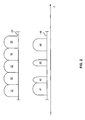
- Fig. 1 schematically illustrates a communication system including a base station 100 and a UE 10 communicating with the base station 100.
- the UE 10 may be, e.g., a mobile phone, portable computer, or other type of UE.
- the UE 10 communicates with the base station 100 via a radio link 20.
- the base station 100 may be an eNB and the radio link 20 may be established using the Uu radio interface.
- the radio link 20 may carry data traffic in the DL direction from the base station 100 to the UE 10 and/or in the UL direction from the UE 10 to the base station 100.
- carrier aggregation may be used on the radio link 20 between the UE 10 and the base station 100, e.g., using the concepts as explained above in the background section. That is to say, a constellation of multiple CCs may be used for transmitting radio signals on the radio link 20 between the UE 10 and the radio base station 100.
- a constellation of multiple CCs may be used for transmitting radio signals on the radio link 20 between the UE 10 and the radio base station 100.
- f denotes the frequency
- different exemplary constellations 30, 40 are illustrated.
- the constellation 30 is illustrated as including adjacent CCs 31, 32, 33, 34, and 35.
- the CCs 31, 32, 33, 34, and 35 may correspond to LTE Rel-8 carriers, and each CC may have a bandwidth of 20 MHz.
- the constellation 40 is illustrated as including multiple contiguous and non-contiguous CCs 41, 42, 43, and 44, which may be aggregated from discontinuous portions of the frequency spectrum. As illustrated, a part of the CCs may be contiguous, such as the CCs 41 and 42, whereas other CCs may be non-contiguous and appear somewhere else in the frequency spectrum, such as the CCs 43 and 44.
- the component carriers 42 may correspond to LTE Rel-8 carriers, and may each have different bandwidths of up to 20 MHz.
- the CCs 41 and 44 may each have a bandwidth of 20 MHz, and the CCs 42 and 43 may each have a bandwidth of 5 MHz, resulting in an aggregated bandwidth of 50 MHz.
- Other bandwidths could be used as well, e.g., bandwidths selected from the group consisting of 1.4 MHz, 3 MHz, 5 MHz, 10 MHz, 15 MHz, and 20 MHz, as supported by 3GPP LTE.
- the aggregated CCs i.e., configured CCs, may be activated and deactivated as needed. This may be accomplished in a UE-specific manner. That is to say, some CCs may be activated for the UE 10, while they are deactivated for another UE and vice versa.
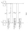
- Fig. 3 illustrates retransmission procedures in the communication system. More specifically, Fig. 3 illustrates transmissions and retransmissions between the UE 10 and the base station 100.
- the retransmission procedures may be implemented on the basis of a retransmission protocol on the MAC layer, in particular on the basis of the HARQ protocol as used in 3GPP LTE.
- the transmissions and retransmissions may each correspond to a respective HARQ process.
- the retransmission processes are typically implemented on a transmission carrier level.
- a retransmission on the same transmission carrier is triggered by a repeat request. If the defective transmission was on a DL SCC, the repeat request may be sent on the corresponding UL SCC.
- there may be multiple HARQ processes in parallel on the same CC For example, one HARQ process may be waiting for its retransmission while another parallel HARQ process receives the first transmission.
- Fig. 3 illustrates procedures corresponding to a single HARQ process.
- the eNB 100 sends a transmission 301 of data to the UE 10.
- the transmission 301 of data may be on a DL SCC, e.g., on one from a plurality of aggregated CCs as illustrated in Fig. 2 .
- the transmission 301 of data is received by the UE 10.
- the UE 10 then performs a check to determine if the received transmission 301 of data is defective. This may be accomplished during decoding of the received transmission 301. For example, if decoding is not successful, the received transmission 301 can be determined to be defective.
- the UE 10 sends a repeat request 303, e.g., in the form of a HARQ NACK, to the eNB 100 to trigger a retransmission of the data.
- a repeat request 303 may be sent on the corresponding UL SCC, e.g., on a Physical Uplink Control Channel (PUCCH) or in Uplink Control Information (UCI).
- the PUCCH or UCI may be mapped to a PUSCH on the UL SCC.
- the received transmission 301 of data which was found to be defective, may be stored in a buffer, e.g., a HARQ process buffer, by the UE 10 so as to be used as additional information when decoding the retransmission. If the received transmission 301 of data is determined to be not defective, the data may be passed to further processing, e.g., to a higher protocol layer. Further, the UE 10 may acknowledge the correct receipt of the transmission 301 to the eNB, e.g., by sending a HARQ ACK, i.e., an acknowledgement message of the HARQ protocol.
- a HARQ ACK i.e., an acknowledgement message of the HARQ protocol.
- the eNB receives the repeat request 303 and, in response to the repeat request, sends a retransmission 304 of the data to the UE 10. If the defective transmission 301 was on a particular DL SCC, the retransmission 304 is sent on the same DL SCC. The retransmission 304 is received by the UE 10.
- the UE 10 then performs a check to determine if the received retransmission 304 is defective. This may be accomplished during decoding of the received retransmission 304. For example, if decoding is not successful, the received retransmission 304 can determined to be defective. When decoding the retransmission 304, the stored transmission 301 can be used as additional information, thereby increasing the chances of successful decoding.
- the UE 10 sends a further repeat request 306, e.g., in the form of a HARQ NACK, to the eNB 100 to trigger a further retransmission of the data.
- a further repeat request 306 may be sent on the corresponding UL SCC, e.g., on the PUCCH or in the UCI, which may be mapped to the PUSCH on the UL SCC.
- the defective received retransmission 304 may be stored in the buffer, e.g., a HARQ process buffer, by the UE 10 so as to be used as additional information when decoding the further retransmission. If the received retransmission 304 of data is determined to be not defective, the data may be passed to further processing, e.g., to a higher protocol layer. Further, the UE 10 may acknowledge the correct receipt of the retransmission 304 to the eNB, e.g., by sending a HARQ ACK, i.e., an acknowledgement message of the HARQ protocol.
- a HARQ ACK i.e., an acknowledgement message of the HARQ protocol.
- the eNB 100 receives the further repeat request 306 and, in response to the further repeat request 306, sends a further retransmission 307 of the data to the UE 10. If the defective transmission 301, and the defective retransmission 304 were on a particular DL SCC, the further retransmission 307 is sent on the same DL SCC. The further retransmission 307 is received by the UE 10.
- the UE 10 then may then proceed in the same way as with the retransmission 304 and perform a check to determine if the received further retransmission 308 is defective.
- This the process of retransmission, check, and repeat request may be iterated until successful decoding of a retransmission is possible.
- the process may also be aborted when reaching a predefined maximum number of retransmissions or after expiry of a timer. Recovery of the unsuccessful data transmission attempt may then be accomplished at higher protocol layers.
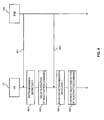
- Fig. 4 shows handling of a deactivation command for causing deactivation of a transmission carrier.
- the deactivation command has the purpose of deactivating the transmission carrier used for receiving the transmission 301 and possible associated retransmissions 304 and 307 of Fig. 3 .
- the deactivation command may further have the purpose of deactivating other transmission carriers.
- the deactivation command may have the purpose of deactivating a plurality of transmission carriers, e.g., a group of DL SCCs.
- the deactivation command may deactivate one or more UL SCCs together with the corresponding DL SCC.
- the eNB 100 sends the deactivation command 401 to the UE 10.
- the deactivation command 401 may be sent on a DL PCC or on a DL SCC, e.g., the same as used for the transmission 301 and the associated possible retransmissions 304 and 307 or another DL SCC.
- the deactivation command 401 may be transmitted in a MAC CE, e.g., in the form of one or more flags or bits, e.g., in the form of a bitmap, to indicate the transmission carrier or transmission carriers to be deactivated.
- each flag or bit in the MAC CE may indicate deactivation of a SCell, i.e., a DL SCC and corresponding UL SCC.
- the deactivation command 401 is received by the UE 10. As indicated by block 402, the UE 10 then performs a check to determine if a retransmission is expected on the transmission carrier to be deactivated. This may be accomplished on the basis of outstanding repeat requests. For example, when receiving the deactivation command 401 during the procedure of Fig. 3 , after sending the repeat request 303, but before correctly receiving the retransmission 304, the UE 10 may determine that the retransmission 304 is expected. Similarly, when receiving the deactivation command 401 after sending the further repeat request 306, but before correctly receiving the further retransmission 307, the UE 10 may determine that the retransmission 307 is expected.
- the UE 10 delays execution of the deactivation command 401. This delay may be until the expected retransmission is received or until a timer has expired. In particular, the UE 10 may delay the deactivation command 401 until all started HARQ retransmission timers for the DL SCC to be deactivated, for all DL SCCs, or for all DL CCs have expired. On the other hand, if the UE 10 determines that no retransmission is expected, the UE 10 may execute the deactivation command 401 without further delay.
- the eNB 100 sends the expected retransmission 404, which is received by the UE 10.
- the retransmission 404 may correspond to the retransmission 304 or to the further retransmission 307 of Fig. 3 .
- the UE 10 may then further perform a check if the received retransmission 404 is defective. This may correspond to the check of block 305 or to the check of block 308 as explained in connection with Fig. 3 .
- the UE 10 may further delay execution of the deactivation command 401. This delay may be until a further retransmission is received or until a timer has expired. In particular, the UE 10 may delay the deactivation command 401 until all started HARQ retransmission timers on that component carrier or on all DL SCCs or on all DL CCs have expired. On the other hand, if the UE 10 determines that the received retransmission 404 is not defective, the UE 10 may execute the deactivation command 401 without further delay.
- deactivation of the transmission carrier does not adversely affect ongoing retransmission processes, and loss of data is avoided.
- the deactivation can occur as soon as ongoing retransmission processes have been concluded.
- the use of the timer avoids deadlock situations, e.g., if for some reason an expected retransmission is never received.
- Fig. 5 depicts, in a table format, a scenario in which the eNB transmits data on a DL PCC, denoted as DL-PCC, and three additional DL SCCs, denoted as DL-SCC1, DL-SCC2, and DL-SCC3.
- the first line in the table shows a sequence of subframes or HARQ processes which may correspond, e.g., to 1 ms each.
- the lower four lines of the table show the data blocks transmitted on the component carriers in each subframe, a transmission being denoted by a "T".
- Transmissions denoted by a "T” in bold and italic type are assumed to be defective and require a retransmission which, since synchronous retransmissions are assumed, is performed at the next occurrence of the process, i.e., eight blocks later, on the same CC.
- Retransmissions are denoted by a "R”.
- Retransmissions denoted by a "R” in bold and italic type are assumed to be defective and require a further retransmission which is performed at the next occurrence of the process, i.e., eight blocks later, on the same CC.
- the eNB sends a MAC CE to deactivate the SCCs (subframes marked with black boxes, position indicated by vertical arrow), e.g., due to a lack of new data.
- a flag may set in the corresponding transport blocks sent in this subframe.
- the deactivation may be specific to particular SCCs. However, in the illustrated scenario, the deactivation is caused for all SCCs.
- the HARQ process 4 on DL-SCC2 requires two more retransmissions because also the first retransmission is not correctly received.
- the UE delays the deactivation of at least DL-SCC2 until the retransmission is received successfully.
- the deactivation of the DL SCCs is illustrated by the shaded area. As illustrated, all SCCs are deactivated simultaneously.
- Fig. 6 illustrates the same scenario as Fig. 5 , but with a delayed deactivation for DL-SCC2 only.
- the delayed deactivation of one or more SCCs can be achieved by keeping an SCC activated if a DL data transmission could not be decoded correctly.
- the UE sends a HARQ NACK in order to request a retransmission.
- this retransmission may come after one HARQ RTT (when assuming synchronous HARQ), but it may also come after several subframes (when assuming asynchronous HARQ).
- the UE may also delay the deactivation command until the data in all soft buffers of the DL SCC to be deactivated was successfully decoded. In other words, the UE may not deactivate the DL SCC if one or more processes are still pending for a HARQ retransmission. To prevent dead-lock situations, the UE may also deactivate the DL SCC as soon as the HARQ RTT Timers and the drx-RetransmissionTimer associated with all HARQ Processes of the DL SCC to be deactivated have expired.
- the HARQ processes on all activated SCCs of the UE prior to deactivation of an SCC may be required to fulfil the above-mentioned conditions. This ensures that no DL SCC is deactivated unless all HARQ processes on all DL SCCs have been successfully decoded or until at least the associated HARQ RTT Timers and drx-RetransmissionTimer have expired. This may be advantageous if the the physical layer data encoding, e.g., a PUCCH or UCI on PUSCH format, depends on the CCs.
- the physical layer data encoding e.g., a PUCCH or UCI on PUSCH format
- the physical data layer encoding performed by the UE may depend on the activated SCCs. For example, depending on PUCCH format and PUCCH resource reservation, this may apply for the PUCCH or UCI on PUSCH format. It may then be desirable to ensure that the UE does not change these formats autonomously so that the eNB is aware of the format to be received. This can be achieved by having the UE apply a configured PUCCH or UCI on PUSCH format until all original transmissions and retransmissions on all CCs have been completed and acknowledged on PUCCH or UCI on PUSCH.
- the UE may also delay the change of the PUCCH or UCI on PUSCH format until it has acknowledged the successful reception of all HARQ processes on all DL SCCs.
- Fig. 7 shows a scenario for illustrating effects of the deactivation of DL SCCs on the UL.
- the DL transmission illustrated in the upper table, is similar to Fig. 5 .
- Fig. 7 illustrates UL transmissions on UL CCs, which include an UL PCC, denoted as UL-PCC, and three UL SCCs, denoted as UL-SCC1, UL-SCC2, and UL-SCC3.
- the UL transmissions include the HARQ feedback, denoted by "F" corresponding to the DL transmissions.
- the UL-PCC includes the HARQ feedback for the DL-PCC
- the UL-SCC1 includes the HARQ feedback for the DL-SCC1
- the UL-SCC2 includes the HARQ feedback for the DL-SCC2
- the UL-SCC3 includes the HARQ feedback for the DL-SCC3.
- an "F" in bold and italic type indicates a negative acknowledgement which triggers a retransmission of a data block 4 subframes later in the DL.
- the HARQ feedback is sent 4 ms after the corresponding data block has been received.
- the shaded area in the lower table indicates that the UE uses another PUCCH or UCI on PUSCH format than before.
- the change appears once all pending retransmissions on any DL SCC have been completed and acknowledged. Further transmissions on the PDSCH of the DL PCC are acknowledged according to the new format, e.g., as shown in the last HARQ process 5 in the lower table of Fig. 7 .
- HARQ feedback e.g., HARQ ACK/NACK
- HARQ ACK/NACK ACK/NACK
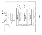
- Fig. 8 schematically illustrates an exemplary structure for implementing the above-described concepts in a transmitter, e.g., in the UE of Figs. 1 , 3 , and 4 .
- the transmitter includes an interface 130 for data transmission via a plurality of transmission carriers, e.g., using the above described concepts of carrier aggregation. More specifically, the interface 130 is adapted to be used for receiving the above-described data transmissions 301, retransmissions 304, 307, and 404, and deactivation commands 401. For this purpose, the interface 130 is provided with a receiver unit 132. Further, the interface 130 is adapted to be used for sending the above-described repeat requests 303, 306. For this purpose, the interface is provided with a transmitter unit 134.
- the interface 130 is configured for data transmission via a radio link. For example, the interface 130 may correspond to the Uu radio interface according to the 3GPP TSs.
- the transmitter includes a processor 150 coupled to the interface 130 and a memory 160 coupled to the processor 150.
- the memory 160 may include a read-only memory (ROM), e.g. a flash ROM, a random-access memory (RAM), e.g. a Dynamic RAM (DRAM) or static RAM (SRAM), a mass storage, e.g. a hard disk or solid state disk, or the like.
- the memory 160 includes suitably configured program code to be executed by the processor 150 so as to implement the above-described functionalities of the transmitter. More specifically, the memory 160 may include a retransmission protocol module 170 for implementing functionalities of data transmission using retransmissions triggered by repeat requests as explained in connection with Fig. 3 .
- the memory 160 may include an activity control module for controlling activation and deactivation of the transmission carriers configured in the interface 130.
- the activity control may in part be implemented in response to receiving commands, e.g., the above-described deactivation command for deactivating one or more of the transmission carriers configured in the interface 130.
- the memory 160 may include a delay control module for delaying execution of a received deactivation command as explained in connection with Fig. 4 .
- the structure as illustrated in Fig. 8 is merely schematic and that the transmitter may actually include further components which, for the sake of clarity, have not been illustrated, e.g., further interfaces.
- the memory 160 may include further types of program code modules, which have not been illustrated.
- the memory 160 may include program code modules for implementing typical functionalities of a UE.
- a computer program product may be provided for implementing concepts according to embodiments of the invention, e.g., a computer-readable medium storing the program code and/or other data to be stored in the memory 160.
- Fig. 9 shows a flowchart for schematically illustrating a method according to an embodiment of the invention. The method may be used for implementing the above-described processes of activity control in a transmitter, e.g., in the UE of Figs. 1 , 3 and 4 .
- the method may include receiving transmissions of data in the transmitter.
- the transmissions of data may be received on at least one transmission carrier, e.g., a DL SCC.
- a transmission carrier e.g., a DL SCC.
- the transmission of data may be performed using a corresponding interface of the communication device, e.g., the interface 130 as explained in connection with Fig. 10.
- the receiver unit 132 may be used for receiving the transmissions of data.
- Receiving the transmissions of data may also involve decoding the transmissions of data and performing a check whether a received transmission of data is defective.
- Decoding and performing the check whether a received transmission of data is defective may be accomplished by a processor, e.g., the processor 150 of Fig. 8 . If a received transmission of data is determined to be defective, a repeat request may be sent by the transmitter to trigger a retransmission of this data, e.g., as explained in connection with Fig. 3 . Further, if retransmissions are triggered, the method may also include receiving retransmissions, decoding the retransmissions, and performing a check whether a received retransmission is defective. If a received retransmission of data is determined to be defective, a repeat request may be sent by the transmitter to trigger a further retransmission, e.g., as explained in connection with Fig. 3 .
- the transmitter receives a deactivation command, e.g., the deactivation command 401 of Fig. 4 .
- the deactivation command may have the purpose of causing a deactivation of one or more transmission carriers, e.g., CCs as explained in connection with Fig. 2 , in particular SCCs. These transmission carriers are used by the transmitter to receive the transmissions of data and possibly also the associated retransmissions.
- the transmitter may receive the transmissions on a plurality of transmission carriers, and the deactivation command may have the purpose of deactivating all of these transmission carriers.
- Execution of the deactivation command may also cause deactivation of one or more transmission carrier, e.g., of one or more SCCs, while at least one further transmission carrier remains active, e.g., a PCC or one or more other SCCs.
- the deactivation command may be received from a base station, e.g., from an eNB.
- the deactivation command may be received in a MAC CE, e.g. in the form of one or more flags or bits, e.g., in the form of a bitmap.
- Execution of the deactivation command may deactivate a transmission carrier for receiving transmissions, e.g., a DL SCC, together with a corresponding transmission carrier for sending transmissions, e.g., an UL SCC corresponding to a DL SCC.
- a transmission carrier for receiving transmissions e.g., a DL SCC
- a corresponding transmission carrier for sending transmissions e.g., an UL SCC corresponding to a DL SCC.
- the transmitter performs a check to determine if a retransmission, in particular a retransmission on the transmission carrier or transmission carriers to be deactivated, is expected. For this purpose, the transmitter may determine if a repeat request to trigger the retransmission was sent by the transmitter and the retransmission is not yet correctly received by the transmitter. The transmitter may also determine that a retransmission is expected if sending of a repeat request was triggered, which may be accomplished already before sending the repeat request. The transmitter may also determine that a retransmission is expected after detecting that a received transmission or retransmission is defective, which may be accomplished already before triggering sending of the repeat request. If this is the case, the transmitter may determine that a retransmission is expected.
- step 930 If the check of step 930 yields that no retransmission is expected, the method continues with step 940, as indicated by branch "N". If the check of step 930 yields that a retransmission is expected, the method continues with step 950, as indicated by branch "Y".
- step 940 the deactivation command is executed and the at least one transmission carrier is deactivated according to the deactivation command.
- step 950 execution of the deactivation command is delayed, e.g., as explained in connection with Fig. 4 .
- execution of the deactivation command may be delayed for all of these transmission carriers so that the transmission carriers may be deactivated simultaneously, e.g., as illustrated in Fig. 5 .
- execution of the deactivation command may be delayed for only those of the transmission carriers on which a retransmission is expected, e.g., as illustrated in Fig. 6 .
- step 960 execution of the deactivation command is delayed until the expected retransmission is received or a timer has expired, e.g., as explained in connection with Fig. 4 .
- Expiry of the timer may indicate that the transmitter should stop waiting for a requested retransmission.
- the timer may be a retransmission timer of a HARQ protocol, e.g., a HARQ RTT Timer and/or a drx-RetransmissionTimer.
- execution of the deactivation command may be delayed at least until the received transmissions of data and/or the received retransmissions have been decoded.
- the transmitter may further delay the execution of the deactivation command, e.g., until at least one further retransmission is received or a timer has expired.
- the transmitter may execute the deactivation command, i.e., deactivate the at least one transmission carrier according to the deactivation command.
- the present invention relates to a method for controlling the activity of a transmitter, e.g., the UE 10, in a communication system with repeat requests.
- the transmitter is adapted to receive data on at least one transmission carrier, e.g., a CC as illustrated in Fig. 2 , and to receive a command for deactivation, e.g., the deactivation command 401, of the at least one transmission carrier.
- the transmitter performs a check if a retransmission is expected for data that was received on the transmission carrier. If this is not the case the carrier is deactivated according to the command. If this is the case, the execution of the command is delayed until the retransmission is received.
- a retransmission may in particular be expected if a retransmission request was sent and the retransmission is not yet correctly received.
- the execution of the command may, if the retransmission is defective, thus be further delayed until one or more further retransmissions are received.
- a transmitter adapted to the proposed method may comprise a receiver unit, e.g., the receiver unit 132, for receiving data and deactivation commands.
- a transmitter unit e.g., the transmitter unit 134, is adapted to send repeat requests.
- a processor in the transmitter e.g., the processor 150, is adapted to check the correct data reception and to trigger the repeat requests.
- the processor is further adapted to control the deactivation of one or more carriers in the receiver unit in response to the deactivation commands.
- a control routine in the processor e.g. as implemented by the delay control module 190, may determine if repeat requests are triggered and delay the deactivation until the triggered retransmission is received.
- the transmitter can be for example a user equipment, e.g. of an LTE system
- the receiver unit may be adapted to receive data on a plurality of carriers, e.g., a plurality of aggregated CCs as explained in connection with Fig. 2 .
- the eNB may deduce the deactivation from the feedback it receives from the UE. For example, if the eNB does not schedule any new data on any of the CCs for which it sent a deactivation command and receives a repeat request, e.g., a HARQ NACK, it may conclude that the UE kept the corresponding DL SCC active and is awaiting the retransmission.
- a repeat request e.g., a HARQ NACK
Landscapes
- Engineering & Computer Science (AREA)
- Signal Processing (AREA)
- Computer Networks & Wireless Communication (AREA)
- Mobile Radio Communication Systems (AREA)
- Detection And Prevention Of Errors In Transmission (AREA)
Claims (17)
- Verfahren zur Aktivitätssteuerung einer Übertragungsvorrichtung (10) in einem Kommunikationssystem mit Wiederholungsanforderungen, wobei die Übertragungsvorrichtung (10) dazu ausgestaltet ist, Daten auf wenigstens einem Übertragungsträger (31, 32 , 33, 34, 35; 41, 42, 43, 44) zu empfangen, wobei das Verfahren umfasst:die Übertragungsvorrichtung (10) empfängt ein Deaktivierungs-, kommando (401) zur Deaktivierung des wenigstens einen Übertragungsträgers (31, 32, 33, 34, 35; 41, 42, 43, 44),in Reaktion auf das Deaktivierungskommando (401) führt die Übertragungsvorrichtung (10) eine Überprüfung durch, ob eine erneute Übertragung (304, 307; 404) auf dem wenigstens einen Übertragungsträger (31, 32, 33, 34, 35; 41, 42, 43, 44) erwartet wird; undwenn eine erneute Übertragung (304, 307; 404) erwartet wird, Verzögern einer Ausführung des Deaktivierungskommandos (401) bis die erneute Übertragung (304, 307; 404) empfangen wird oder ein Timer abgelaufen ist.
- Verfahren nach Anspruch 1,
wobei die Übertragungsvorrichtung (10) bestimmt, dass eine erneute Übertragung (304, 307; 404) erwartet wird, wenn eine Wiederholungsanforderung (303, 306) zum Auslösen der erneuten Übertragung (304, 307; 404) von der Übertragungsvorrichtung (10) ausgesendet wurde und die erneute Übertragung (304, 307; 404) noch nicht korrekt von der Übertragungsvorrichtung (10) empfangen wurde. - Verfahren nach Anspruch 1 oder 2, umfassend:die Übertragungsvorrichtung (10) empfängt Übertragungen (301) von Daten auf dem wenigstens einen Übertragungsträger (31, 32, 33, 34, 35; 41, 42, 43, 44);die Übertragungsvorrichtung (10) führt eine Überprüfung durch, ob die empfangenen Übertragungen (301) von Daten fehlerhaft sind, undwenn eine der empfangenen Übertragungen (301) von Daten fehlerhaft ist, sendet die Übertragungsvorrichtung (10) eine Wiederholungsanforderung zum Auslösen der erneuten Übertragung (304) dieser Daten.
- Verfahren nach Anspruch 3,
wobei Ausführung des Deaktivierungskommandos (401) zumindest verzögert wird, bis die empfangenen Übertragungen (301) von Daten dekodiert wurden. - Verfahren nach einem der vorhergehenden Ansprüche, umfassend:die Übertragungsvorrichtung (10) empfängt die erneute Übertragung (304, 307; 404); unddie Übertragungsvorrichtung (10) führt eine Überprüfung durch, ob die empfangene erneute Übertragung (304, 307; 404) fehlerhaft ist; undwenn die empfangene erneute Übertragung (304, 307; 404) fehlerhaft ist, weiteres Verzögern des Deaktivierungskommandos, bis wenigstens eine weitere erneute Übertragung (307) empfangen wird oder ein Timer abgelaufen ist.
- Verfahren nach Anspruch 5,
wobei eine Ausführung des Deaktivierungskommandos (401) zumindest verzögert wird, bis die empfangenen erneute Übertragung (304, 307; 404) dekodiert wurde. - Verfahren nach einem der vorhergehenden Ansprüche,
wobei eine Ausführung des Deaktivierungskommandos (401) eine Deaktivierung von wenigstens einem Übertragungsträger (31, 32, 33, 34, 35; 41, 42, 43, 44) bewirkt, während wenigstens ein weiterer Übertragungsträger (31, 32, 33, 34, 35; 41, 42, 43, 44) aktiv bleibt. - Verfahren nach einem der vorhergehenden Ansprüche,
wobei eine Ausführung des Deaktivierungskommandos (401) eine Deaktivierung einer Vielzahl von Übertragungsträgern (31, 32, 33, 34, 35; 41, 42, 43, 44) bewirkt; und
wobei eine Ausführung des Deaktivierungskommandos (401) für alle Übertragungsträger (31, 32, 33, 34, 35; 41, 42, 43, 44) dieser Vielzahl verzögert wird. - Verfahren nach einem der Ansprüche 1 bis 7,
wobei eine Ausführung des Deaktivierungskommandos (401), eine Deaktivierung einer Vielzahl von Übertragungsträgern (31, 32, 33, 34, 35; 41, 42, 43, 44) bewirkt; und
wobei eine Ausführung des Deaktivierungskommandos (401) nur für diejenigen der Übertragungsträger (31, 32, 33, 34, 35; 41, 42, 43, 44) aus der Vielzahl verzögert wird, auf welchen eine erneute Übertragung (304, 307; 404) erwartet wird. - Verfahren nach einem der vorhergehenden Ansprüche,
wobei die Übertragungen (301) von Daten und erneuten Übertragungen (304, 307; 404) Übertragungen und erneute Übertragungen eines Hybrid-Automatic-Repeat-Request-Protokolls sind. - Übertragungsvorrichtung (10), umfassend:eine Empfängereinheit (132), welche dazu ausgestaltet ist, Übertragungen (301) von Daten, erneute Übertragungen (304, 307; 404), und Deaktivierungskommandos (401) zu empfangen;eine Sendeeinheit (134), welche dazu ausgestaltet ist, Wiederholungsanforderungen (303, 306) zu senden; undeinen Prozessor (150), welcher dazu ausgestaltet ist, eine Deaktivierung von Übertragungsträgern (31, 32, 33, 34, 35; 41, 42, 43, 44) zu steuern durch Ausführen eines empfangenen Deaktivierungskommandos (401) zur Deaktivierung wenigstens eines Übertragungsträgers (31, 32, 33, 34, 35; 41, 42, 43, 44), welcher von der Empfängereinheit (132) zum Empfangen der Übertragungen (301) von Daten verwendet wird,wobei der Prozessor (150) weiterhin dazu ausgestaltet ist, eine Überprüfung durchzuführen, ob eine erneute Übertragung (304, 307; 404) auf dem wenigstens einen Übertragungsträger (31, 32, 33, 34, 35; 41, 42, 43, 44) erwartet wird und, wenn eine erneute Übertragung (304, 307; 404) erwartet wird, eine Ausführung des Deaktivierungskommandos (401) zu verzögern, bis die erneute Übertragung (304, 307; 404) empfangen wird oder ein Timer abgelaufen ist.
- Übertragungsvorrichtung (10) nach Anspruch 11,
wobei der Prozessor (150) dazu ausgestaltet ist, zu Bestimmen, dass eine erneute Übertragung (304, 307; 404) erwartet wird, wenn eine Wiederholungsanforderung (303, 306) zum Auslösen der erneuten Übertragung (304, 307; 404) gesendet wurde und die erneute Übertragung (304, 307; 404) noch nicht korrekt empfangen wurde. - Übertragungsvorrichtung (10) nach Anspruch 11 oder 12,
wobei der Prozessor (150) weiterhin dazu ausgestaltet ist, eine Überprüfung durchzuführen, ob empfangene Übertragungen von Daten (301) fehlerhaft sind, und wenn eine der empfangenen Übertragungen von Daten (301) fehlerhaft ist, ein Senden einer Wiederholungsanforderung (303) durch die Sendeeinheit (134) auszulösen. - Übertragungsvorrichtung (10) nach einem der Ansprüche 11 bis 13,
wobei der Prozessor (150) weiterhin dazu ausgestaltet ist, eine Überprüfung durchzuführen, ob die empfangene erneute Übertragung (304, 307; 404) fehlerhaft ist, und wenn die empfangene erneute Übertragung (304, 307; 404) fehlerhaft ist, eine Ausführung des Deaktivierungskommandos (401) weiter zu verzögern, bis wenigstens eine weitere erneute Übertragung (307) empfangen wird oder ein Timer abgelaufen ist. - Übertragungsvorrichtung (10) nach einem der Ansprüche 11 bis 14,
wobei die Übertragungsvorrichtung dazu ausgestaltet ist, gemäß einem Verfahren zu arbeiten, wie es in einem der Ansprüche 1 bis 10 definiert ist. - Kommunikationssystem umfassend:eine Übertragungsvorrichtung (10); undeine Basisstation (100),wobei die Basisstation (100) dazu ausgestaltet ist, Übertragungen (301) von Daten, erneute Übertragungen (304, 307; 404) und Deaktivierungskommandos (401) an die Übertragungsvorrichtung (10) zu senden;wobei die Übertragungsvorrichtung (10) dazu ausgestaltet ist, die Übertragungen (301) von Daten, die erneuten Übertragungen (304, 307; 404) und die Deaktivierungskommandos (401) von der Basisstation (100) zu empfangen und Wiederholungsanforderungen (303, 306) an die Basisstation (100) zu senden, um die erneuten Übertragungen (304, 307; 404) auszulösen; undwobei die Übertragungsvorrichtung (10) weiterhin dazu ausgestaltet ist, eine Deaktivierung von Übertragungsträgern (31, 32, 33, 34, 35; 41, 42, 43, 44) zu steuern durch Ausführen eines empfangenen Deaktivierungskommandos (401) zur Deaktivierung wenigstens eines Übertragungsträgers (31, 32, 33, 34, 35; 41, 42, 43, 44), welcher zum Empfangen der Übertragungen (301) von Daten verwendet wird, undwobei die Übertragungsvorrichtung (10) weiterhin dazu ausgestaltet ist, eine Überprüfung durchzuführen, ob eine erneute Übertragung (304, 307; 404) auf dem wenigstens einen Übertragungsträger (31, 32, 33, 34, 35; 41, 42, 43, 44) erwartet wird, und wenn eine erneute Übertragung (304, 307; 404) erwartet wird, eine Ausführung des Deaktivierungskommandos (401) zu verzögern, bis die erneute Übertragung (304, 307; 404) empfangen wird oder ein Timer abgelaufen ist.
- Kommunikationssystem nach Anspruch 16,
wobei die Übertragungsvorrichtung (10) dazu ausgestaltet ist, gemäß einem Verfahren zu arbeiten, wie es in einem der Ansprüche 1 bis 10 definiert ist.
Applications Claiming Priority (2)
| Application Number | Priority Date | Filing Date | Title |
|---|---|---|---|
| US32002110P | 2010-04-01 | 2010-04-01 | |
| EP11711888.5A EP2553854B1 (de) | 2010-04-01 | 2011-04-01 | Methoden und vorrichtungen zur steuerung der abschaltung von ausstrahlungsträgern |
Related Parent Applications (1)
| Application Number | Title | Priority Date | Filing Date |
|---|---|---|---|
| EP11711888.5A Division EP2553854B1 (de) | 2010-04-01 | 2011-04-01 | Methoden und vorrichtungen zur steuerung der abschaltung von ausstrahlungsträgern |
Publications (2)
| Publication Number | Publication Date |
|---|---|
| EP2747331A1 EP2747331A1 (de) | 2014-06-25 |
| EP2747331B1 true EP2747331B1 (de) | 2015-10-21 |
Family
ID=44070596
Family Applications (2)
| Application Number | Title | Priority Date | Filing Date |
|---|---|---|---|
| EP14160843.0A Not-in-force EP2747331B1 (de) | 2010-04-01 | 2011-04-01 | Methoden und Vorrichtungen zur Steuerung der Abschaltung von Ausstrahlungsträgern |
| EP11711888.5A Not-in-force EP2553854B1 (de) | 2010-04-01 | 2011-04-01 | Methoden und vorrichtungen zur steuerung der abschaltung von ausstrahlungsträgern |
Family Applications After (1)
| Application Number | Title | Priority Date | Filing Date |
|---|---|---|---|
| EP11711888.5A Not-in-force EP2553854B1 (de) | 2010-04-01 | 2011-04-01 | Methoden und vorrichtungen zur steuerung der abschaltung von ausstrahlungsträgern |
Country Status (4)
| Country | Link |
|---|---|
| US (2) | US9065650B2 (de) |
| EP (2) | EP2747331B1 (de) |
| CN (1) | CN102893548B (de) |
| WO (1) | WO2011121132A1 (de) |
Families Citing this family (28)
| Publication number | Priority date | Publication date | Assignee | Title |
|---|---|---|---|---|
| KR101752502B1 (ko) * | 2010-01-07 | 2017-06-30 | 엘지전자 주식회사 | 무선 통신 시스템에서 요소 반송파 관리 방법 및 장치 |
| WO2011142634A2 (en) * | 2010-05-13 | 2011-11-17 | Samsung Electronics Co., Ltd. | Method and system for bulk activation/deactivation of component carriers in a wireless network environment |
| KR101614096B1 (ko) * | 2010-08-12 | 2016-04-29 | 한국전자통신연구원 | 이동통신 시스템에서 멀티 캐리어 구조를 위한 채널 관리 방법 |
| US20120057539A1 (en) * | 2010-09-07 | 2012-03-08 | Richard Lee-Chee Kuo | Method and apparatus for hybrid automatic repeat request in a wireless communication system |
| KR102092579B1 (ko) | 2011-08-22 | 2020-03-24 | 삼성전자 주식회사 | 이동통신 시스템에서 복수 개의 주파수 밴드 지원 방법 및 장치 |
| KR20140116090A (ko) * | 2011-12-08 | 2014-10-01 | 인터디지탈 패튼 홀딩스, 인크 | 하이 레이트 이중 대역 셀룰러 통신 |
| EP2849501B1 (de) | 2012-05-09 | 2020-09-30 | Samsung Electronics Co., Ltd. | Verfahren und vorrichtung zur steuerung des unregelmässigen empfangs in einem mobilen kommunikationssystem |
| WO2013168917A1 (ko) * | 2012-05-09 | 2013-11-14 | 삼성전자 주식회사 | 이동통신 시스템에서 복수의 캐리어를 이용해서 데이터를 송수신하는 방법 및 장치 |
| JP6138246B2 (ja) | 2012-06-09 | 2017-05-31 | アップル インコーポレイテッド | キャリアアグリゲーション可能無線通信装置におけるrfチェーン管理 |
| EP3031281B1 (de) * | 2013-08-09 | 2021-04-14 | Nokia Solutions and Networks Oy | Verwendung von paketstatusberichten aus einer sekundären basisstation an eine primäre basisstation in einem drahtlosen netzwerk |
| US20160262185A1 (en) * | 2015-03-03 | 2016-09-08 | Intel IP Corporation | Orthogonal frequency division multiple access based distributed channel access |
| CN106470050B (zh) * | 2015-08-12 | 2021-01-22 | 中兴通讯股份有限公司 | 实现基站间协作多点CoMP下行传输的方法及相应的基站 |
| US9756654B2 (en) | 2015-10-28 | 2017-09-05 | Cisco Technology, Inc. | Timer-based scheme for user equipment queue state estimation |
| US10193664B2 (en) * | 2016-06-13 | 2019-01-29 | Intel IP Corporation | Enhanced retry count for uplink multi-user transmission |
| CN114040456B (zh) | 2016-08-10 | 2024-11-15 | 日本电气株式会社 | 无线接入网节点及其方法 |
| EP3499966B1 (de) | 2016-08-10 | 2024-08-14 | Nec Corporation | Funkzugangsnetzwerkknoten, drahtloses endgerät und verfahren dafür |
| EP3793253B1 (de) | 2016-08-10 | 2024-09-18 | NEC Corporation | Funkzugangsnetzwerkknoten, kernnetzwerkknoten und verfahren dafür |
| CN109526252B (zh) * | 2016-08-10 | 2021-09-17 | 日本电气株式会社 | 无线接入网节点、无线终端、核心网节点及其方法 |
| CN108282781A (zh) * | 2017-01-06 | 2018-07-13 | 中兴通讯股份有限公司 | 移动过程中的数据传输的方法、终端和基站 |
| FI3646502T3 (fi) | 2017-08-10 | 2025-09-03 | Beijing Xiaomi Mobile Software Co Ltd | Uplink-ohjaustietojen multipleksointi |
| CN109428696B (zh) * | 2017-08-24 | 2020-11-03 | 电信科学技术研究院 | 一种重复传输的激活/去激活方法、基站、终端及装置 |
| CN109561472B (zh) * | 2017-09-26 | 2020-07-14 | 展讯通信(上海)有限公司 | 用户设备及其去激活bwp的方法、计算机可读介质 |
| CN109756309B (zh) * | 2017-11-01 | 2022-05-13 | 中兴通讯股份有限公司 | 去激活辅成员载波的方法、装置及介质 |
| CN109802781B (zh) * | 2017-11-16 | 2023-01-06 | 夏普株式会社 | 用于处理载波激活的方法及其设备 |
| US11968154B2 (en) * | 2017-12-19 | 2024-04-23 | Qualcomm Incorporated | Carrier aggregation SCell new state transition design |
| WO2019203711A1 (en) | 2018-04-20 | 2019-10-24 | Telefonaktiebolaget Lm Ericsson (Publ) | Cross-carrier spatial relation indication for semi-persistent sounding reference signal (sp-srs) resources |
| CN110635879B (zh) | 2018-06-22 | 2021-02-23 | 维沃移动通信有限公司 | 一种bwp去激活定时器的控制方法及终端设备 |
| WO2020226549A1 (en) * | 2019-05-03 | 2020-11-12 | Telefonaktiebolaget Lm Ericsson (Publ) | Configured grant uplink control information (uci) mapping rules |
Family Cites Families (9)
| Publication number | Priority date | Publication date | Assignee | Title |
|---|---|---|---|---|
| US8897234B2 (en) * | 2005-09-07 | 2014-11-25 | Huawei Technologies Co., Ltd. | Method and apparatus for controlling carrier frequency in multi-carrier/cell system |
| EP2078399A2 (de) | 2006-11-02 | 2009-07-15 | Telefonaktiebolaget LM Ericsson (PUBL) | Verfahren und anordnung in einem telekommunikationssystem |
| MX2009007592A (es) * | 2007-01-26 | 2009-09-10 | Electrolux Ab | Aspiradora. |
| US7899003B2 (en) | 2007-08-13 | 2011-03-01 | Sharp Laboratories Of America, Inc. | Method and system for control of discontinuous reception (DRX) by a mobile device in a wireless communications network supporting voice-over-internet-protocol (VoIP) |
| US8934405B2 (en) | 2008-05-06 | 2015-01-13 | Telefonaktiebolaget L M Ericsson (Publ) | Method and apparatus for retransmission scheduling and control in multi-carrier wireless communication networks |
| MX2010011830A (es) | 2008-06-19 | 2010-11-25 | Ericsson Telefon Ab L M | Metodo y aparato en una red de telecomunicaciones. |
| US8514793B2 (en) * | 2008-10-31 | 2013-08-20 | Interdigital Patent Holdings, Inc. | Method and apparatus for monitoring and processing component carriers |
| KR20110094760A (ko) * | 2010-02-17 | 2011-08-24 | 주식회사 팬택 | 다수의 요소 반송파를 운영하는 무선 통신 시스템에서 불연속 수신 방법 및 장치와, 그를 위한 활성/비활성 지시 메시지 송신방법 및 장치 |
| US9363059B2 (en) * | 2010-04-02 | 2016-06-07 | Acer Incorporated | Method of handling component carrier activation and deactivation and communication device thereof |
-
2011
- 2011-04-01 EP EP14160843.0A patent/EP2747331B1/de not_active Not-in-force
- 2011-04-01 US US13/636,602 patent/US9065650B2/en active Active
- 2011-04-01 WO PCT/EP2011/055146 patent/WO2011121132A1/en not_active Ceased
- 2011-04-01 EP EP11711888.5A patent/EP2553854B1/de not_active Not-in-force
- 2011-04-01 CN CN201180017352.2A patent/CN102893548B/zh not_active Expired - Fee Related
-
2015
- 2015-06-15 US US14/739,359 patent/US9363065B2/en not_active Expired - Fee Related
Also Published As
| Publication number | Publication date |
|---|---|
| EP2553854A1 (de) | 2013-02-06 |
| EP2747331A1 (de) | 2014-06-25 |
| WO2011121132A1 (en) | 2011-10-06 |
| EP2553854B1 (de) | 2014-03-26 |
| US20130010611A1 (en) | 2013-01-10 |
| US9065650B2 (en) | 2015-06-23 |
| CN102893548B (zh) | 2016-02-24 |
| US9363065B2 (en) | 2016-06-07 |
| US20150280891A1 (en) | 2015-10-01 |
| CN102893548A (zh) | 2013-01-23 |
Similar Documents
| Publication | Publication Date | Title |
|---|---|---|
| EP2747331B1 (de) | Methoden und Vorrichtungen zur Steuerung der Abschaltung von Ausstrahlungsträgern | |
| JP6316871B2 (ja) | 信号送受信方法及びそのための装置 | |
| EP2391046B1 (de) | Verfahren zur Abwicklung von Komponententrägeraktivierung und -deaktivierung und entsprechende Kommunikationsvorrichtung | |
| US10595166B2 (en) | Systems and methods for processing time reduction signaling | |
| US9794900B2 (en) | Method of handling uplink timing and related communication device | |
| EP2393232B1 (de) | Verfahren zum Umgang mit einer HARQ Einheit und Kommunikationseinrichtung dafür | |
| EP2518927B1 (de) | Verfahren zur Handhabung eines Weichpufferspeichers zur Speicheraggregation und zugehörige Kommunikationsvorrichtung | |
| EP2383927B1 (de) | Verfahren und Vorrichtung zum Wiederanlauf eines Komponententrägerzeituhr in einem drahtlosen Kommunikationssystem | |
| EP3110212B1 (de) | Mobilkommunikationssystem und benutzervorrichtung | |
| US20180048447A1 (en) | User equipments, base stations and methods | |
| KR101689864B1 (ko) | 교차 캐리어 스케줄링 제어 방법 및 장치 | |
| US20140119339A1 (en) | Method for controlling error for carrier aggregation and apparatus for same | |
| CN105981324B (zh) | 用于在支持无线资源的使用的变化的无线通信系统中发送回退模式的上行链路信号的方法及其设备 | |
| US20150049653A1 (en) | Method and system for handling ue behavior in inter-band carrier aggregation with cell specific tdd configuration | |
| CN110505711A (zh) | 处理调度请求的方法、设备、装置及介质 | |
| US9888494B2 (en) | Data sending method and device in spectrum aggregation |
Legal Events
| Date | Code | Title | Description |
|---|---|---|---|
| PUAI | Public reference made under article 153(3) epc to a published international application that has entered the european phase |
Free format text: ORIGINAL CODE: 0009012 |
|
| 17P | Request for examination filed |
Effective date: 20140320 |
|
| AC | Divisional application: reference to earlier application |
Ref document number: 2553854 Country of ref document: EP Kind code of ref document: P |
|
| AK | Designated contracting states |
Kind code of ref document: A1 Designated state(s): AL AT BE BG CH CY CZ DE DK EE ES FI FR GB GR HR HU IE IS IT LI LT LU LV MC MK MT NL NO PL PT RO RS SE SI SK SM TR |
|
| R17P | Request for examination filed (corrected) |
Effective date: 20141222 |
|
| RBV | Designated contracting states (corrected) |
Designated state(s): AL AT BE BG CH CY CZ DE DK EE ES FI FR GB GR HR HU IE IS IT LI LT LU LV MC MK MT NL NO PL PT RO RS SE SI SK SM TR |
|
| GRAP | Despatch of communication of intention to grant a patent |
Free format text: ORIGINAL CODE: EPIDOSNIGR1 |
|
| INTG | Intention to grant announced |
Effective date: 20150508 |
|
| RAP1 | Party data changed (applicant data changed or rights of an application transferred) |
Owner name: TELEFONAKTIEBOLAGET L M ERICSSON (PUBL) |
|
| GRAS | Grant fee paid |
Free format text: ORIGINAL CODE: EPIDOSNIGR3 |
|
| GRAA | (expected) grant |
Free format text: ORIGINAL CODE: 0009210 |
|
| AC | Divisional application: reference to earlier application |
Ref document number: 2553854 Country of ref document: EP Kind code of ref document: P |
|
| AK | Designated contracting states |
Kind code of ref document: B1 Designated state(s): AL AT BE BG CH CY CZ DE DK EE ES FI FR GB GR HR HU IE IS IT LI LT LU LV MC MK MT NL NO PL PT RO RS SE SI SK SM TR |
|
| REG | Reference to a national code |
Ref country code: GB Ref legal event code: FG4D |
|
| REG | Reference to a national code |
Ref country code: CH Ref legal event code: EP |
|
| REG | Reference to a national code |
Ref country code: AT Ref legal event code: REF Ref document number: 757211 Country of ref document: AT Kind code of ref document: T Effective date: 20151115 |
|
| REG | Reference to a national code |
Ref country code: IE Ref legal event code: FG4D |
|
| REG | Reference to a national code |
Ref country code: DE Ref legal event code: R096 Ref document number: 602011020926 Country of ref document: DE |
|
| REG | Reference to a national code |
Ref country code: LT Ref legal event code: MG4D |
|
| REG | Reference to a national code |
Ref country code: AT Ref legal event code: MK05 Ref document number: 757211 Country of ref document: AT Kind code of ref document: T Effective date: 20151021 |
|
| REG | Reference to a national code |
Ref country code: NL Ref legal event code: FP |
|
| PG25 | Lapsed in a contracting state [announced via postgrant information from national office to epo] |
Ref country code: HR Free format text: LAPSE BECAUSE OF FAILURE TO SUBMIT A TRANSLATION OF THE DESCRIPTION OR TO PAY THE FEE WITHIN THE PRESCRIBED TIME-LIMIT Effective date: 20151021 Ref country code: IS Free format text: LAPSE BECAUSE OF FAILURE TO SUBMIT A TRANSLATION OF THE DESCRIPTION OR TO PAY THE FEE WITHIN THE PRESCRIBED TIME-LIMIT Effective date: 20160221 Ref country code: NO Free format text: LAPSE BECAUSE OF FAILURE TO SUBMIT A TRANSLATION OF THE DESCRIPTION OR TO PAY THE FEE WITHIN THE PRESCRIBED TIME-LIMIT Effective date: 20160121 Ref country code: IT Free format text: LAPSE BECAUSE OF FAILURE TO SUBMIT A TRANSLATION OF THE DESCRIPTION OR TO PAY THE FEE WITHIN THE PRESCRIBED TIME-LIMIT Effective date: 20151021 Ref country code: ES Free format text: LAPSE BECAUSE OF FAILURE TO SUBMIT A TRANSLATION OF THE DESCRIPTION OR TO PAY THE FEE WITHIN THE PRESCRIBED TIME-LIMIT Effective date: 20151021 Ref country code: LT Free format text: LAPSE BECAUSE OF FAILURE TO SUBMIT A TRANSLATION OF THE DESCRIPTION OR TO PAY THE FEE WITHIN THE PRESCRIBED TIME-LIMIT Effective date: 20151021 |
|
| PG25 | Lapsed in a contracting state [announced via postgrant information from national office to epo] |
Ref country code: PT Free format text: LAPSE BECAUSE OF FAILURE TO SUBMIT A TRANSLATION OF THE DESCRIPTION OR TO PAY THE FEE WITHIN THE PRESCRIBED TIME-LIMIT Effective date: 20160222 Ref country code: AT Free format text: LAPSE BECAUSE OF FAILURE TO SUBMIT A TRANSLATION OF THE DESCRIPTION OR TO PAY THE FEE WITHIN THE PRESCRIBED TIME-LIMIT Effective date: 20151021 Ref country code: LV Free format text: LAPSE BECAUSE OF FAILURE TO SUBMIT A TRANSLATION OF THE DESCRIPTION OR TO PAY THE FEE WITHIN THE PRESCRIBED TIME-LIMIT Effective date: 20151021 Ref country code: GR Free format text: LAPSE BECAUSE OF FAILURE TO SUBMIT A TRANSLATION OF THE DESCRIPTION OR TO PAY THE FEE WITHIN THE PRESCRIBED TIME-LIMIT Effective date: 20160122 Ref country code: SE Free format text: LAPSE BECAUSE OF FAILURE TO SUBMIT A TRANSLATION OF THE DESCRIPTION OR TO PAY THE FEE WITHIN THE PRESCRIBED TIME-LIMIT Effective date: 20151021 Ref country code: FI Free format text: LAPSE BECAUSE OF FAILURE TO SUBMIT A TRANSLATION OF THE DESCRIPTION OR TO PAY THE FEE WITHIN THE PRESCRIBED TIME-LIMIT Effective date: 20151021 Ref country code: RS Free format text: LAPSE BECAUSE OF FAILURE TO SUBMIT A TRANSLATION OF THE DESCRIPTION OR TO PAY THE FEE WITHIN THE PRESCRIBED TIME-LIMIT Effective date: 20151021 Ref country code: PL Free format text: LAPSE BECAUSE OF FAILURE TO SUBMIT A TRANSLATION OF THE DESCRIPTION OR TO PAY THE FEE WITHIN THE PRESCRIBED TIME-LIMIT Effective date: 20151021 |
|
| REG | Reference to a national code |
Ref country code: DE Ref legal event code: R097 Ref document number: 602011020926 Country of ref document: DE |
|
| PG25 | Lapsed in a contracting state [announced via postgrant information from national office to epo] |
Ref country code: CZ Free format text: LAPSE BECAUSE OF FAILURE TO SUBMIT A TRANSLATION OF THE DESCRIPTION OR TO PAY THE FEE WITHIN THE PRESCRIBED TIME-LIMIT Effective date: 20151021 |
|
| PLBE | No opposition filed within time limit |
Free format text: ORIGINAL CODE: 0009261 |
|
| STAA | Information on the status of an ep patent application or granted ep patent |
Free format text: STATUS: NO OPPOSITION FILED WITHIN TIME LIMIT |
|
| PG25 | Lapsed in a contracting state [announced via postgrant information from national office to epo] |
Ref country code: SK Free format text: LAPSE BECAUSE OF FAILURE TO SUBMIT A TRANSLATION OF THE DESCRIPTION OR TO PAY THE FEE WITHIN THE PRESCRIBED TIME-LIMIT Effective date: 20151021 Ref country code: RO Free format text: LAPSE BECAUSE OF FAILURE TO SUBMIT A TRANSLATION OF THE DESCRIPTION OR TO PAY THE FEE WITHIN THE PRESCRIBED TIME-LIMIT Effective date: 20151021 Ref country code: EE Free format text: LAPSE BECAUSE OF FAILURE TO SUBMIT A TRANSLATION OF THE DESCRIPTION OR TO PAY THE FEE WITHIN THE PRESCRIBED TIME-LIMIT Effective date: 20151021 Ref country code: DK Free format text: LAPSE BECAUSE OF FAILURE TO SUBMIT A TRANSLATION OF THE DESCRIPTION OR TO PAY THE FEE WITHIN THE PRESCRIBED TIME-LIMIT Effective date: 20151021 Ref country code: SM Free format text: LAPSE BECAUSE OF FAILURE TO SUBMIT A TRANSLATION OF THE DESCRIPTION OR TO PAY THE FEE WITHIN THE PRESCRIBED TIME-LIMIT Effective date: 20151021 Ref country code: BE Free format text: LAPSE BECAUSE OF NON-PAYMENT OF DUE FEES Effective date: 20160430 |
|
| 26N | No opposition filed |
Effective date: 20160722 |
|
| PG25 | Lapsed in a contracting state [announced via postgrant information from national office to epo] |
Ref country code: SI Free format text: LAPSE BECAUSE OF FAILURE TO SUBMIT A TRANSLATION OF THE DESCRIPTION OR TO PAY THE FEE WITHIN THE PRESCRIBED TIME-LIMIT Effective date: 20151021 |
|
| REG | Reference to a national code |
Ref country code: CH Ref legal event code: PL |
|
| PG25 | Lapsed in a contracting state [announced via postgrant information from national office to epo] |
Ref country code: LU Free format text: LAPSE BECAUSE OF FAILURE TO SUBMIT A TRANSLATION OF THE DESCRIPTION OR TO PAY THE FEE WITHIN THE PRESCRIBED TIME-LIMIT Effective date: 20160401 Ref country code: BE Free format text: LAPSE BECAUSE OF FAILURE TO SUBMIT A TRANSLATION OF THE DESCRIPTION OR TO PAY THE FEE WITHIN THE PRESCRIBED TIME-LIMIT Effective date: 20151021 |
|
| REG | Reference to a national code |
Ref country code: IE Ref legal event code: MM4A |
|
| REG | Reference to a national code |
Ref country code: FR Ref legal event code: ST Effective date: 20161230 |
|
| PG25 | Lapsed in a contracting state [announced via postgrant information from national office to epo] |
Ref country code: LI Free format text: LAPSE BECAUSE OF NON-PAYMENT OF DUE FEES Effective date: 20160430 Ref country code: FR Free format text: LAPSE BECAUSE OF NON-PAYMENT OF DUE FEES Effective date: 20160502 Ref country code: CH Free format text: LAPSE BECAUSE OF NON-PAYMENT OF DUE FEES Effective date: 20160430 |
|
| PG25 | Lapsed in a contracting state [announced via postgrant information from national office to epo] |
Ref country code: IE Free format text: LAPSE BECAUSE OF NON-PAYMENT OF DUE FEES Effective date: 20160401 |
|
| PG25 | Lapsed in a contracting state [announced via postgrant information from national office to epo] |
Ref country code: HU Free format text: LAPSE BECAUSE OF FAILURE TO SUBMIT A TRANSLATION OF THE DESCRIPTION OR TO PAY THE FEE WITHIN THE PRESCRIBED TIME-LIMIT; INVALID AB INITIO Effective date: 20110401 |
|
| PG25 | Lapsed in a contracting state [announced via postgrant information from national office to epo] |
Ref country code: MC Free format text: LAPSE BECAUSE OF FAILURE TO SUBMIT A TRANSLATION OF THE DESCRIPTION OR TO PAY THE FEE WITHIN THE PRESCRIBED TIME-LIMIT Effective date: 20151021 Ref country code: MK Free format text: LAPSE BECAUSE OF FAILURE TO SUBMIT A TRANSLATION OF THE DESCRIPTION OR TO PAY THE FEE WITHIN THE PRESCRIBED TIME-LIMIT Effective date: 20151021 Ref country code: MT Free format text: LAPSE BECAUSE OF NON-PAYMENT OF DUE FEES Effective date: 20160430 Ref country code: CY Free format text: LAPSE BECAUSE OF FAILURE TO SUBMIT A TRANSLATION OF THE DESCRIPTION OR TO PAY THE FEE WITHIN THE PRESCRIBED TIME-LIMIT Effective date: 20151021 |
|
| PG25 | Lapsed in a contracting state [announced via postgrant information from national office to epo] |
Ref country code: BG Free format text: LAPSE BECAUSE OF FAILURE TO SUBMIT A TRANSLATION OF THE DESCRIPTION OR TO PAY THE FEE WITHIN THE PRESCRIBED TIME-LIMIT Effective date: 20151021 |
|
| PG25 | Lapsed in a contracting state [announced via postgrant information from national office to epo] |
Ref country code: TR Free format text: LAPSE BECAUSE OF FAILURE TO SUBMIT A TRANSLATION OF THE DESCRIPTION OR TO PAY THE FEE WITHIN THE PRESCRIBED TIME-LIMIT Effective date: 20151021 Ref country code: AL Free format text: LAPSE BECAUSE OF FAILURE TO SUBMIT A TRANSLATION OF THE DESCRIPTION OR TO PAY THE FEE WITHIN THE PRESCRIBED TIME-LIMIT Effective date: 20151021 |
|
| PGFP | Annual fee paid to national office [announced via postgrant information from national office to epo] |
Ref country code: NL Payment date: 20220426 Year of fee payment: 12 |
|
| PGFP | Annual fee paid to national office [announced via postgrant information from national office to epo] |
Ref country code: GB Payment date: 20220427 Year of fee payment: 12 Ref country code: DE Payment date: 20220427 Year of fee payment: 12 |
|
| REG | Reference to a national code |
Ref country code: DE Ref legal event code: R119 Ref document number: 602011020926 Country of ref document: DE |
|
| REG | Reference to a national code |
Ref country code: NL Ref legal event code: MM Effective date: 20230501 |
|
| GBPC | Gb: european patent ceased through non-payment of renewal fee |
Effective date: 20230401 |
|
| PG25 | Lapsed in a contracting state [announced via postgrant information from national office to epo] |
Ref country code: GB Free format text: LAPSE BECAUSE OF NON-PAYMENT OF DUE FEES Effective date: 20230401 |
|
| PG25 | Lapsed in a contracting state [announced via postgrant information from national office to epo] |
Ref country code: NL Free format text: LAPSE BECAUSE OF NON-PAYMENT OF DUE FEES Effective date: 20230501 Ref country code: GB Free format text: LAPSE BECAUSE OF NON-PAYMENT OF DUE FEES Effective date: 20230401 Ref country code: DE Free format text: LAPSE BECAUSE OF NON-PAYMENT OF DUE FEES Effective date: 20231103 |