EP2747179A1 - Lattice for storage battery, method for producing lattice for storage battery, and storage battery using lattice for storage battery - Google Patents
Lattice for storage battery, method for producing lattice for storage battery, and storage battery using lattice for storage battery Download PDFInfo
- Publication number
- EP2747179A1 EP2747179A1 EP13835776.9A EP13835776A EP2747179A1 EP 2747179 A1 EP2747179 A1 EP 2747179A1 EP 13835776 A EP13835776 A EP 13835776A EP 2747179 A1 EP2747179 A1 EP 2747179A1
- Authority
- EP
- European Patent Office
- Prior art keywords
- bone
- bones
- slanted
- storage battery
- side portion
- Prior art date
- Legal status (The legal status is an assumption and is not a legal conclusion. Google has not performed a legal analysis and makes no representation as to the accuracy of the status listed.)
- Granted
Links
Images



Classifications
-
- H—ELECTRICITY
- H01—ELECTRIC ELEMENTS
- H01M—PROCESSES OR MEANS, e.g. BATTERIES, FOR THE DIRECT CONVERSION OF CHEMICAL ENERGY INTO ELECTRICAL ENERGY
- H01M4/00—Electrodes
- H01M4/02—Electrodes composed of, or comprising, active material
- H01M4/64—Carriers or collectors
- H01M4/70—Carriers or collectors characterised by shape or form
- H01M4/72—Grids
- H01M4/74—Meshes or woven material; Expanded metal
- H01M4/742—Meshes or woven material; Expanded metal perforated material
-
- H—ELECTRICITY
- H01—ELECTRIC ELEMENTS
- H01M—PROCESSES OR MEANS, e.g. BATTERIES, FOR THE DIRECT CONVERSION OF CHEMICAL ENERGY INTO ELECTRICAL ENERGY
- H01M4/00—Electrodes
- H01M4/02—Electrodes composed of, or comprising, active material
- H01M4/64—Carriers or collectors
- H01M4/70—Carriers or collectors characterised by shape or form
- H01M4/72—Grids
- H01M4/73—Grids for lead-acid accumulators, e.g. frame plates
-
- H—ELECTRICITY
- H01—ELECTRIC ELEMENTS
- H01M—PROCESSES OR MEANS, e.g. BATTERIES, FOR THE DIRECT CONVERSION OF CHEMICAL ENERGY INTO ELECTRICAL ENERGY
- H01M10/00—Secondary cells; Manufacture thereof
- H01M10/06—Lead-acid accumulators
-
- H—ELECTRICITY
- H01—ELECTRIC ELEMENTS
- H01M—PROCESSES OR MEANS, e.g. BATTERIES, FOR THE DIRECT CONVERSION OF CHEMICAL ENERGY INTO ELECTRICAL ENERGY
- H01M4/00—Electrodes
- H01M4/02—Electrodes composed of, or comprising, active material
- H01M4/64—Carriers or collectors
- H01M4/66—Selection of materials
- H01M4/68—Selection of materials for use in lead-acid accumulators
- H01M4/685—Lead alloys
-
- H—ELECTRICITY
- H01—ELECTRIC ELEMENTS
- H01M—PROCESSES OR MEANS, e.g. BATTERIES, FOR THE DIRECT CONVERSION OF CHEMICAL ENERGY INTO ELECTRICAL ENERGY
- H01M4/00—Electrodes
- H01M4/02—Electrodes composed of, or comprising, active material
- H01M4/64—Carriers or collectors
- H01M4/82—Multi-step processes for manufacturing carriers for lead-acid accumulators
-
- Y—GENERAL TAGGING OF NEW TECHNOLOGICAL DEVELOPMENTS; GENERAL TAGGING OF CROSS-SECTIONAL TECHNOLOGIES SPANNING OVER SEVERAL SECTIONS OF THE IPC; TECHNICAL SUBJECTS COVERED BY FORMER USPC CROSS-REFERENCE ART COLLECTIONS [XRACs] AND DIGESTS
- Y02—TECHNOLOGIES OR APPLICATIONS FOR MITIGATION OR ADAPTATION AGAINST CLIMATE CHANGE
- Y02E—REDUCTION OF GREENHOUSE GAS [GHG] EMISSIONS, RELATED TO ENERGY GENERATION, TRANSMISSION OR DISTRIBUTION
- Y02E60/00—Enabling technologies; Technologies with a potential or indirect contribution to GHG emissions mitigation
- Y02E60/10—Energy storage using batteries
-
- Y—GENERAL TAGGING OF NEW TECHNOLOGICAL DEVELOPMENTS; GENERAL TAGGING OF CROSS-SECTIONAL TECHNOLOGIES SPANNING OVER SEVERAL SECTIONS OF THE IPC; TECHNICAL SUBJECTS COVERED BY FORMER USPC CROSS-REFERENCE ART COLLECTIONS [XRACs] AND DIGESTS
- Y02—TECHNOLOGIES OR APPLICATIONS FOR MITIGATION OR ADAPTATION AGAINST CLIMATE CHANGE
- Y02P—CLIMATE CHANGE MITIGATION TECHNOLOGIES IN THE PRODUCTION OR PROCESSING OF GOODS
- Y02P70/00—Climate change mitigation technologies in the production process for final industrial or consumer products
- Y02P70/50—Manufacturing or production processes characterised by the final manufactured product
-
- Y—GENERAL TAGGING OF NEW TECHNOLOGICAL DEVELOPMENTS; GENERAL TAGGING OF CROSS-SECTIONAL TECHNOLOGIES SPANNING OVER SEVERAL SECTIONS OF THE IPC; TECHNICAL SUBJECTS COVERED BY FORMER USPC CROSS-REFERENCE ART COLLECTIONS [XRACs] AND DIGESTS
- Y10—TECHNICAL SUBJECTS COVERED BY FORMER USPC
- Y10T—TECHNICAL SUBJECTS COVERED BY FORMER US CLASSIFICATION
- Y10T29/00—Metal working
- Y10T29/10—Battery-grid making
Definitions
- the present invention relates to a storage battery grid, a method of manufacturing a storage battery grid, and a storage battery using a storage battery grid.
- An expanded grid (i.e., a net-like grid) obtained by forming slits in, for example, a zigzag manner on a lead alloy sheet, followed by expanding, has been conventionally used as a grid for use in a storage battery, as disclosed in Patent Document 1.
- the expanded grid includes an upper frame having a lug portion formed thereat, a lower frame opposed to the upper frame, and a net-like frame formed between the upper frame and the lower frame.
- a space defined by the upper frame, the lower frame, and the net-like frame is filled with an active material, thereby constituting an electrode plate.
- the expanded grid has no frame bone for connecting the upper frame and the lower frame to each other on right and left sides, and therefore, is liable to be elongated in a height direction, and further, is likely to be curved and deformed in a planar direction, thereby raising a problem that the active material tends to fall down.
- the net-like frame of the expanded grid is serrate from the lower frame to the upper frame, and therefore, a current channel up to the lug portion becomes long, thereby increasing an electric resistance. Consequently, a potential distribution becomes uneven over the entire electrode plate, thereby raising problems of local corrosion and a short lifetime of the electrode plate.
- a cast grid including, inside of a square frame bone, many lateral frames parallel to each other and many radial frames radially extending from a lug portion disposed on an upper side of the frame bone is conceived as a grid for use in a storage battery, as disclosed in Patent Document 2.
- the radial frames are formed with branch frames.
- Each of the branch frames includes: a branch starting frame extending sideways at a large angle with respect to the base of the radial frame; and a bent starting frame continuous to the branch starting frame and bent in a radial direction.
- the cast grid includes a portion that does not extend toward the lug portion (in particular, the branch starting frame) on a channel from the lower section toward the upper section along the branch frame, and therefore, a current channel up to the lug portion becomes long, resulting in an increase in electric resistance. Consequently, a potential distribution becomes uneven over the entire electrode plate, thereby raising problems of local corrosion and a short lifetime of the electrode plate.
- a main object of the present invention is to enhance the mechanical strength of a grid, and further, reduce the electric resistance of the grid to regularize a potential distribution of the grid.
- a storage battery grid includes: a frame bone that includes a substantially rectangular shape; a lug portion that is connected to a first side portion of the frame bone and projects outwardly from the frame bone; a main bone that extends from a connection portion of the first side portion, to which the lug portion is connected, to a second side portion which is opposed to the first side portion; a sub-bone that extends from the first side portion to the second side portion; and a plurality of slanted bones that extend obliquely toward the second side portion, at least the plurality of slanted bones branching from the main bone toward both sides, wherein the plurality of slanted bones are arranged at intervals in a direction in which the main bone extends, and at least part of a plurality of spaces, which are defined by the main bone and the sub-bone that are partially forming sides of the spaces, include a substantially quadrilateral shape.
- a method of manufacturing a storage battery grid according to the present invention includes: forming a frame bone that includes a substantially rectangular shape; forming a lug portion that is connected to a first side portion of the frame bone and projects outwardly from the frame bone; forming a main bone that extends from a connection portion of the first side portion, to which the lug portion is connected, to a second side portion which is opposed to the first side portion; forming a sub-bone that extends from the first side portion to the second side portion; forming a plurality of slanted bones that extend obliquely toward the second side portion, at least the plurality of slanted bones branching from the main bone toward both sides; arranging the plurality of slanted bones at intervals in a direction in which the main bone extends; and causing at least part of a plurality of spaces, which are defined by the main bone and the sub-bone that are partially forming sides of the spaces, to include a substantially quadrilateral shape.
- the grid is provided with the sub-bone and at least the plurality of slanted bones extending slantwise from the main bone, thereby shortening a channel of a current, which is generated at a portion apart from the connection portion between the main bone and the second side portion of the frame bone, to the lug portion.
- the space defined by the main bone, the sub-bone, and the slanted bones includes a substantially quadrilateral shape, thereby reducing the number of bypass channels apart from the lug portion in comparison with a substantially triangular space. Consequently, in the entire grid, an electric resistance can be reduced and the potential distribution of the grid can be made uniform.
- the grid includes the frame bone formed into the rectangular shape, thus enhancing a mechanical strength.
- part of the plurality of slanted bones branches from the first side portion of the frame bone.
- the channel of a current generated on both sides of the main bone includes the slanted bones and the first side portion in a linear manner, thus shortening a current channel so as to reduce the electric resistance of the grid.
- part of the plurality of slanted bones branches from the connection portion, to which the lug portion is connected in the first side portion of the frame bone.
- the sub-bone includes a plurality of sub-bones arranged at intervals in a direction in which the first side portion extends, and the intervals of the sub-bones increase in a direction away from the main bone.
- the intervals between the sub-bones can be optimized depending on collected electric power. Consequently, the potential distribution of the grid can be made more uniform.
- a plurality of spaces which are defined by the second side portion, the sub-bone and the slanted bone that are partially forming sides of the spaces, include a substantially quadrilateral shape.
- the main bone is arranged perpendicularly to the first side portion and the second side portion.
- the lug portion and the second side portion of the frame bone can be connected to each other with the shortest distance, and therefore, the electric resistance of the grid can be further reduced.
- the grid is devoid of a lateral bone that is substantially parallel to the first side portion of the frame bone.
- the channel of the current which is generated on both sides of the main bone, includes only the channel having a directional component orienting from the second side portion to the first side portion, and therefore, the channel reaching the main bone or the lug portion can be shortened, and the electric resistance of the grid can be reduced.
- intervals of the slanted bones which are part of the plurality of slanted bones and branching from the main bone, increase as the slanted bones extend away from the first side portion.
- the interval between the slanted bones can be optimized depending on collected electric power.
- the potential distribution of the grid can be made more uniform.
- a slant angle of the slanted bones relative to the main bone increases as the slanted bones extend away from the first side portion, the slanted bones being part of the plurality of slanted bones and branching from the main bone.
- the slant angle of the slanted bone can be optimized depending on collected electric power.
- the potential distribution of the grid can be made more uniform.
- a slant angle of the plurality of slanted bones is in a range from 5 degrees to 60 degrees. With this configuration, the channel reaching the main bone can be shortened. It is particularly preferable that the slant angle of the slanted bone is 45°.
- a width of the main bone in a plan view decreases as it extends away from the lug portion.
- the shape of the main bone can be optimized depending on collected electric power. In other words, the width of a portion, which is apart from the lug portion and electric quantity flowing thereto is small, can be reduced. Thus, the material of the grid can be reduced and cost can be reduced.
- a width of the first side portion in a plan view increases as it approaches to the lug portion.
- a storage battery according to the present invention uses any one of the above-described storage battery grids.
- the potential distribution of the grid can be made uniform, and a high rate discharge performance can be enhanced.
- the mechanical strength can be enhanced, and a cycle life performance can be enhanced.
- the storage battery grid is made from a lead alloy.
- the present invention is applicable to the lead-acid storage battery grid.
- the storage battery grid is formed by blanking.
- the thickness of the grid can be reduced (i.e., the mass of the grid can be reduced) in comparison with a grid formed by casting.
- the material of the grid can be reduced and cost can be reduced.
- the rectangular frame bone includes the main bone and the slanted bone, thus enhancing the mechanical strength of the grid.
- the grid is provided with the plurality of slanted bones slantwise branched from the first side portion of the frame bone and the main bone, which extends from the connection portion of the first side portion to which the lug portion is connected, thus reducing the electric resistance of the grid, making the potential distribution of the grid uniform.
- a grid 1 in the present embodiment is used as one member of a positive plate or a negative plate in an electrode group serving as a power generating element for a lead-acid storage battery.
- the grid 1 is filled with a positive active material (i.e., lead dioxide).
- the grid 1 is filled with a negative active material (i.e., spongy lead).
- the grid 1 is obtained by blanking a rolled sheet made of a lead alloy. As shown in Figs. 1 and 2 , the grid 1 includes a frame bone 2 formed into a substantially rectangular shape, a lug portion 21 projecting from an upper side 2a (i.e., a first side portion) of the frame bone 2 upward outside of a frame, a plurality of vertical bones 3 vertically extending in a linear manner inside of the frame bone 2, and a plurality of slanted bones 4 slantwise formed inside of the frame bone 2.
- the grid 1 in the present embodiment is devoid of a lateral bone substantially parallel to the upper side 2a of the frame bone 2.
- the grid 1 includes, out of the plurality of vertical bones 3, a main vertical bone 3X (i.e., a main bone) formed of one or more vertical bones 3 (three in the present embodiment) extending downward from right under a connection portion 5 to the lug portion 21 at the upper side 2a.
- the main vertical bone 3X is substantially perpendicular to the upper side 2a of the frame bone 2 and a lower side 2b (i.e., a second side portion) opposite to the upper side 2a, and is tapered with a gradually reduced width from the upper section to the lower section, as viewed on a plane. This can make the shape of a vertical bone most suitable for collected electric power. Since a width dimension is smaller at the lower section, a material of an electrode plate can be reduced.
- the plurality of vertical bones 3 i.e., sub-bones
- the plurality of vertical bones 3 arranged on right and left sides of the main vertical bone 3X are arranged at intervals in the lateral direction (i.e., the extending direction) of the upper side 2a, and they are formed such that the intervals become greater as they are more apart from the main vertical bone 3X toward the right and left sides.
- the plurality of vertical bones 3 arranged on the right and left sides of the main vertical bone 3X are configured such that the width of each of them becomes smaller as they are more apart from the main vertical bone 3X. This can make the interval between the vertical bones 3 most suitable for collected electric power.
- the plurality of vertical bones 3 may be configured such that the width of each of them becomes smaller as they are more apart from the main vertical bone 3X.
- the plurality of slanted bones 4 include at least slanted bones 4 extending slantwise downward from the main vertical bone 3X in a linear manner.
- the plurality of slanted bones 4 include: a plurality of slanted bones 4 (4m) branched from the main vertical bone 3X and extending slantwise downward; and a plurality of slanted bones 4 (4n) branched from the upper side 2a of the frame bone 2 and extending slantwise downward.
- Some (two in the present embodiment) of the slanted bones 4 are branched from the connection portion 5 to the lug portion 21 at the upper side 2a.
- the upper ends of the slanted bones 4 are connected to the main vertical bone 3X or the upper side 2a of the frame bone 2; the lower ends of the slanted bones 4 are connected to the sides 2c or 2d or lower side 2b of the frame bone 2. In other words, the lower ends of the slanted bones 4 extend to reach the frame bone 2.
- the plurality of slanted bones 4 are formed into a substantially inverted V shape from the main vertical bone 3X, as viewed on a plane, and therefore, they are branched from at least the main vertical bone 3X rightward and leftward of the main vertical bone 3X, and further, extend slantwise from the upper side 2a to the lower side 2b. Specifically, the plurality of slanted bones 4 are formed into a substantially linear manner in which they are inclined upward near the main vertical bone 3X, as viewed on a plane.
- a space defined by the main vertical bone 3X and the like is formed into a substantially quadrilateral shape.
- the channel of a current generated on the right and left sides of the main vertical bone 3X becomes linear, thereby shortening the channel of a current to the main vertical bone 3X or the upper side 2a.
- the plurality of slanted bones 4 formed on the left side of the main vertical bone 3X are arranged with the intervals in the vertical direction (i.e., the extending direction) of the main vertical bone 3X at an slant angle of 45° with respect to the main vertical bone 3X, as shown in Fig. 3 .
- the plurality of slanted bones 4 formed on the right side of the main vertical bone 3X are arranged with the intervals in the vertical direction of the main vertical bone 3X at an slant angle of 45° with respect to the main vertical bone 3X.
- connection point P1 at the upper end of each of the slanted bones 4 (4m) formed on the left side and a connection point P2 at the upper end of each of the slanted bones 4 (4m) formed on the right side mate with each other in a height direction at the main vertical bone 3X.
- the slanted bones 4 formed on the left side of the main vertical bone 3X and the slanted bones 4 formed on the right side of the main vertical bone 3X are laterally symmetric with each other with respect to the main vertical bone 3X.
- the plurality of slanted bones 4 formed on the left side of the main vertical bone 3X are formed substantially in parallel to each other, and the plurality of slanted bones 4 formed on the right side of the main vertical bone 3X are formed substantially in parallel to each other. In this manner, the plurality of slanted bones 4 are formed substantially in parallel to each other, and therefore, a potential distribution can be made more uniform.
- the interval between the adjacent slanted bones 4 may be identical to each other, may be different from each other, or may be enlarged downward. In other words, the intervals between the slanted bones 4 may be varied so as to make the potential distribution uniform.
- the grid 1 in the present embodiment includes: the frame bone 2 formed into a rectangular shape; the lug portion 21 that is connected to the upper side 2a of the frame bone 2 and projects outward from a frame; the main vertical bone 3X that vertically extends from the connection portion between the upper side 2a and the lug portion 21 to the lower side 2b opposite to the upper side 2a, the width of the main vertical bone 3X becoming smaller apart from the lug portion 21, as viewed on a plane; the plurality of vertical bones 3 extending from the upper side 2a to the lower side 2b, arranged in the extending direction of the upper side 2a of the frame bone 2 with the intervals that become greater apart from the main vertical bone 3X; and the plurality of slanted bones 4 that are branched from at least the main vertical bone 3X toward both sides and extend slantwise toward the lower side 2b at the slant angle from 5° to 60°.
- the plurality of slanted bones 4 are arranged with the intervals in the extending direction of the main vertical bone 3X. Some of the slanted bones 4 are branched from the upper side 2a of the frame bone 2, and further, some of the slanted bones 4 are branched from the connection portion to the lug portion 21 at the upper side 2a of the frame bone 2.
- Each of the plurality of spaces defined by the main vertical bone 3X, the vertical bone 3, and the like is at least partly formed into a substantially quadrilateral shape.
- Each of the plurality of spaces defined by the lower side 2b of the frame bone 2, the vertical bone 3, the slanted bone 4, and the like is partly formed into a substantially quadrilateral shape. Additionally, out of the plurality of slanted bones 4, the intervals between the plurality of slanted bones 4 branched from the main vertical bone 3X become greater apart from the upper side 2a of the frame bone 2.
- the conventional expanded grid had a grid dimension [a width (mm) ⁇ a height (mm)] of 137.0 ⁇ 115.0, a grid thickness (mm) of 1.00, and a grid mass (g) of 42.0.
- the lead-acid storage battery grid according to the present invention had a grid dimension [a width (mm) ⁇ a height (mm)] of 137.0 ⁇ 115.0, a grid thickness (mm) of 0.80, and a grid mass (g) of 42.0.
- a current of 1 A was made to flow at the upper end of the lug portion in each of the conventional expanded grid and the lead-acid storage battery grid according to the present invention, followed by a potential distribution analysis.
- the rate of a potential drop (i.e., a voltage drop) with reference (0V) to a lower frame of the conventional expanded grid is assumed as 100%.
- the rate of a potential drop with reference (0V) to the lower side of the lead-acid storage battery grid according to the present invention and the uniformity of a potential distribution are shown in Table 1.
- the rate of the potential drop of the lead-acid storage battery grid according to the present invention was decreased down to 48% to 50% of that of the conventional expanded grid.
- the uniformity of the potential distribution of the lead-acid storage battery grid according to the present invention was ⁇ or ⁇ (excellent or good), that is, it was more excellent than that of the conventional expanded grid since the uniformity of the potential distribution of the conventional expanded grid was ⁇ (bad). In view of this, it was found that the potential distribution of the entire lead-acid storage battery grid according to the present invention was made to be uniform in comparison with that of the conventional expanded grid.
- the uniformity of the potential distribution of the entire grid when the slant angle of the slanted bone of the lead-acid storage battery grid according to the present invention ranged from 0° to 80° was ⁇ (good), and further, the uniformity of the potential distribution when the slant angle of the slanted bone of the lead-acid storage battery grid according to the present invention ranged from 5° to 60° was ⁇ (excellent). It was found from the results that the potential distribution was made to be more uniform within the range from 5° to 60° of the slant angle of the slanted bone of the lead-acid storage battery grid according to the present invention.
- the use of the lead-acid storage battery grid according to the present invention for a lead-acid storage battery can enhance a high rate discharge performance (a cold cranking current and a low temperature high rate discharge performance) more than the use of the conventional expanded grid when it has almost the same lead mass as that of the conventional expanded grid.
- a high rate discharge performance a cold cranking current and a low temperature high rate discharge performance
- substantially the same high rate discharge performance a cold cranking current and a low temperature high rate discharge performance
- the rate of a grid elongation in the width direction (i.e., the lateral direction) of the conventional expanded grid and the rate of a grid elongation in the height direction (i.e., the vertical direction) of the conventional expanded grid was set to 100%
- the rate of a grid elongation in the width direction in the lead-acid storage battery grid according to the present invention ranged from 50% to 80% of that of the conventional expanded grid
- the rate of a grid elongation in the height direction ranged from 43% to 57%: namely, they were decreased.
- the grid elongation in each of the width direction and the height direction was decreased in the lead-acid storage battery grid according to the present invention.
- the cycle life performance of the lead-acid storage battery using the grid according to the present invention can be enhanced, for example, the number of cycles in a cycle life test at an ambient temperature of 75° pursuant to the light load lifetime test determined by JIS 5301 is increased.
- the main vertical bone 3X is disposed under the lug portion 21, and therefore, the distance between the lug portion 21 and the lower side 2b of the frame bone 2 can be shortened.
- the plurality of slanted bones 4 extend slantwise downward from at least the main vertical bone 3X, and therefore, the channel for a current generated at the sides of the main vertical bone 3X toward the main vertical bone 3X or the lug portion 21 can be shortened.
- the plurality of slanted bones 4 are formed into the substantially inverted V shape on the main vertical bone 3X, as viewed on a plane, and therefore, the channels for currents generated on the right and left sides of the main vertical bone 3X toward the main vertical bone 3X or the lug portion 21 can be shortened. Furthermore, the space defined by the main vertical bone 3X and the slanted bones 4 is formed into the substantially quadrilateral shape, thereby reducing bypass channels remote from the lug portion 2 in comparison with a triangular shape. Consequently, in the entire grid 1, an electric resistance can be decreased and the potential distribution of the electrode plate can be made uniform. In addition, the frame bone 2 is formed into the substantially rectangular shape, thus enhancing a mechanical strength.
- the grid 1 of the present embodiment includes the plurality of vertical bones 3 and the plurality of slanted bones 4 but is devoid of the lateral bone substantially parallel to the upper side 2a of the frame bone 2. Therefore, the channel of the current generated on the right and left sides of the main vertical bone 3X includes only the upward channel formed of the vertical bones 3 and the slantwise upward channel formed of the slanted bones 4. The channel reaching the lug portion 21 via the main vertical bone 3X and the upper side 2a can be shortened, thus reducing the electric resistance.
- the thickness of the grid can be further reduced (that is, the mass of the grid can be further reduced) in comparison with the case where the grid is formed by casting.
- the material of the grid is reduced, thus reducing a cost.
- a difference in thickness of the grid is caused by a difference in corrosion mode due to a difference in metallic tissue.
- a cast grid has a large crystalline grain. Corrosion proceeds in such a manner as to enter a crystalline grain field, and therefore, the cast grid has characteristics of a small corrosion ratio at which the grid is broken.
- the punched grid manufactured by blanking a rolled sheet is rolled after the fabrication of a slab, so that a large crystalline grain contained in the slab is elongated in a roll direction. In this manner, there is no crystalline grain field that may break the grid, and thus, corrosion sequentially proceeds from the grid surface. With these characteristics, the punched grid manufactured with the rolling sheet can be reduced in grid thickness in comparison with the cast grid.
- the grid 1 is manufactured by blanking or casting in the following manner.
- a rectangular frame bone is formed.
- a lug portion is formed in such a manner as to be connected to a first side portion of the frame bone and project outward of a frame.
- a main bone is formed in such a manner as to extend from a connection portion to the lug portion at the first side portion to a second side portion opposite to the first side portion.
- a sub-bone is formed in such a manner as to extend from the first side portion to the second side portion.
- a plurality of slanted bones are formed in such a manner as to be branched from at least the main bone toward both sides and slantwise extend toward the second side portion. The plurality of slanted bones are arranged at intervals in the extending direction of the main bone.
- Each of a plurality of spaces defined by the main bone, the sub-bones, and the like is at least partly formed into a substantially quadrilateral shape.
- the present invention is not limited to the above-described embodiment.
- the main vertical bone 3X is formed of one vertical bone 3, and the plurality of slanted bones 4 extend from the main vertical bone 3X.
- a main vertical bone 3X may be formed of a plurality of vertical bones 3 (two in Fig. 4 ), and a plurality of slanted bones 4 may extend from the plurality of main vertical bones 3X, as shown in Fig. 4 .
- an upper side 2a of a frame bone 2 may be increased in height toward a lug portion 21, as viewed on a plane.
- the lower surface of the upper side 2a of the frame bone 2 is formed into a substantially V shape inclined downward toward the lug portion 21 from both ends thereof. Consequently, the mechanical strength of a grid 1 can be enhanced, and further, a potential distribution of an electrode plate can be made more uniform.
- FIG. 5 shows a case where three vertical bones 3 on right and left sides of the main vertical bone 3X are decreased in width from the upper section to the lower section.
- the slant angle (e.g., 45°) of each of the plurality of slanted bones 4 on the left side of the main vertical bone 3X and the slant angle (e.g., 45°) of each of the plurality of slanted bones 4 on the right side of the main vertical bone 3X are the same in the above-described embodiment.
- the slant angles of slanted bones 4 on right and left sides may be different from each other.
- the slant angle of each of a plurality of slanted bones 4 on the left side of the main vertical bone 3X may be 45°
- the slant angle of each of a plurality of slanted bones 4 on the right side of the main vertical bone 3X may be 60°.
- the slant angle of each of the slanted bones 4 is 45° in the above-described embodiment, it may be other values. As shown in Fig. 6 , the slant angle of the slanted bone 4 may be 5° in a lateral direction in Fig. 6 (i.e., 85° with respect to a main vertical bone 3X). As shown in Fig. 7 , the slant angle may be 60° (i.e., 30° with respect to a main vertical bone 3X).
- connection portions of the slanted bones 4 on the right and left sides are the same as each other in the height direction in the above-described embodiment, they may be shifted from each other in a height direction, as shown in Figs. 8 and 9 .
- slanted bones 4 are connected to the lower side 2b or side 2c or 2d of the frame bone 2 in the above-described embodiment, some of the slanted bones 4 may not be connected to the lower side 2b or side 2c or 2d of the frame bone 2. For example, as shown in Fig.
- each of a plurality of slanted bones 4 that cross a side 2c or 2d of the frame bone 2 when linearly extending are connected to the side 2c or 2d, like the above-described embodiment: in contrast, out of the plurality of slanted bones 4, the slanted bones 4 that cross a lower side 2b of the frame bone 2 when linearly extending are connected to the vertical bone 3 immediately before or more beforehand of the lower side 2b, and further, an end 4e of the slanted bone 4 is formed at the vertical bone 3 immediately before or more beforehand of the lower side 2b.
- each of a plurality of spaces defined by the lower side 2b and the like is formed into a substantially quadrilateral shape.
- the slant angles of a plurality of slanted bones 4m branched from the main vertical bone 3X with respect to the main vertical bone 3X become greater apart from the upper side 2a of the frame bone 2.
- the slant angle of the slanted bone 4m nearest the upper side 2a is 30° (i.e., 60° with respect to the main vertical bone 3X), and further, the slant angle of the remotest slanted bone 4m is 20° (i.e., 70° with respect to the main vertical bone 3X).
- the optimum slant angle of the slanted bone 4m can be set depending on collected electric power.
- the potential distribution of the grid 1 can be made more uniform, and the workability for filling the grid with the active material can be enhanced.
- the grid includes the plurality of slanted bones 4 (4m) slantwise extending downward from the main vertical bone 3X and the plurality of slanted bones 4 (4n) slantwise extending downward from the upper side 2a of the frame bone 2 in the above-described embodiment, the grid may be devoid of slanted bones 4 (4n) slantwise extending downward from the upper side 2a.
- the grid used for a lead-acid storage battery is exemplified in the above-described embodiment, the present invention is not limited to this.
- the grid according to the present invention is applicable to a grid filled with an active material for a nickel-metal hydride battery and the like.
- the grid 1 is formed by blanking in the above-described embodiment, it may be formed by casting.
- the grid in the above-described embodiment includes the upper side out of the four sides of the frame bone as the first side portion and the lower side as the second side portion, one of the right and left sides out of the four sides of the frame bone may be used as a first side portion whereas the other may be used as a second side portion.
Landscapes
- Chemical & Material Sciences (AREA)
- Chemical Kinetics & Catalysis (AREA)
- Electrochemistry (AREA)
- General Chemical & Material Sciences (AREA)
- Cell Electrode Carriers And Collectors (AREA)
- Secondary Cells (AREA)
- Connection Of Batteries Or Terminals (AREA)
Description
- The present invention relates to a storage battery grid, a method of manufacturing a storage battery grid, and a storage battery using a storage battery grid.
- An expanded grid (i.e., a net-like grid) obtained by forming slits in, for example, a zigzag manner on a lead alloy sheet, followed by expanding, has been conventionally used as a grid for use in a storage battery, as disclosed in
Patent Document 1. The expanded grid includes an upper frame having a lug portion formed thereat, a lower frame opposed to the upper frame, and a net-like frame formed between the upper frame and the lower frame. A space defined by the upper frame, the lower frame, and the net-like frame is filled with an active material, thereby constituting an electrode plate. - However, the expanded grid has no frame bone for connecting the upper frame and the lower frame to each other on right and left sides, and therefore, is liable to be elongated in a height direction, and further, is likely to be curved and deformed in a planar direction, thereby raising a problem that the active material tends to fall down. The net-like frame of the expanded grid is serrate from the lower frame to the upper frame, and therefore, a current channel up to the lug portion becomes long, thereby increasing an electric resistance. Consequently, a potential distribution becomes uneven over the entire electrode plate, thereby raising problems of local corrosion and a short lifetime of the electrode plate.
- In the meantime, a cast grid including, inside of a square frame bone, many lateral frames parallel to each other and many radial frames radially extending from a lug portion disposed on an upper side of the frame bone is conceived as a grid for use in a storage battery, as disclosed in
Patent Document 2. The radial frames are formed with branch frames. Each of the branch frames includes: a branch starting frame extending sideways at a large angle with respect to the base of the radial frame; and a bent starting frame continuous to the branch starting frame and bent in a radial direction. - However, the cast grid includes a portion that does not extend toward the lug portion (in particular, the branch starting frame) on a channel from the lower section toward the upper section along the branch frame, and therefore, a current channel up to the lug portion becomes long, resulting in an increase in electric resistance. Consequently, a potential distribution becomes uneven over the entire electrode plate, thereby raising problems of local corrosion and a short lifetime of the electrode plate.
-
- Patent Document 1:
JP-A-7-320743 - Patent Document 2:
JP-Y 8-2921 - In view of the above, a main object of the present invention is to enhance the mechanical strength of a grid, and further, reduce the electric resistance of the grid to regularize a potential distribution of the grid.
- A storage battery grid according to the present invention includes: a frame bone that includes a substantially rectangular shape; a lug portion that is connected to a first side portion of the frame bone and projects outwardly from the frame bone; a main bone that extends from a connection portion of the first side portion, to which the lug portion is connected, to a second side portion which is opposed to the first side portion; a sub-bone that extends from the first side portion to the second side portion; and a plurality of slanted bones that extend obliquely toward the second side portion, at least the plurality of slanted bones branching from the main bone toward both sides, wherein the plurality of slanted bones are arranged at intervals in a direction in which the main bone extends, and at least part of a plurality of spaces, which are defined by the main bone and the sub-bone that are partially forming sides of the spaces, include a substantially quadrilateral shape.
- A method of manufacturing a storage battery grid according to the present invention includes: forming a frame bone that includes a substantially rectangular shape; forming a lug portion that is connected to a first side portion of the frame bone and projects outwardly from the frame bone; forming a main bone that extends from a connection portion of the first side portion, to which the lug portion is connected, to a second side portion which is opposed to the first side portion; forming a sub-bone that extends from the first side portion to the second side portion; forming a plurality of slanted bones that extend obliquely toward the second side portion, at least the plurality of slanted bones branching from the main bone toward both sides; arranging the plurality of slanted bones at intervals in a direction in which the main bone extends; and causing at least part of a plurality of spaces, which are defined by the main bone and the sub-bone that are partially forming sides of the spaces, to include a substantially quadrilateral shape.
- With the above-described configuration, since the main bone extends from the connection portion of the first side portion, to which the lug portion is connected in the frame bone, to the second side portion, the distance between the lug portion and the second side portion of the frame bone can be reduced. The grid is provided with the sub-bone and at least the plurality of slanted bones extending slantwise from the main bone, thereby shortening a channel of a current, which is generated at a portion apart from the connection portion between the main bone and the second side portion of the frame bone, to the lug portion. In addition, the space defined by the main bone, the sub-bone, and the slanted bones includes a substantially quadrilateral shape, thereby reducing the number of bypass channels apart from the lug portion in comparison with a substantially triangular space. Consequently, in the entire grid, an electric resistance can be reduced and the potential distribution of the grid can be made uniform. In addition, the grid includes the frame bone formed into the rectangular shape, thus enhancing a mechanical strength.
- It is preferable that part of the plurality of slanted bones branches from the first side portion of the frame bone. With this configuration, the channel of a current generated on both sides of the main bone includes the slanted bones and the first side portion in a linear manner, thus shortening a current channel so as to reduce the electric resistance of the grid.
- It is preferable that part of the plurality of slanted bones branches from the connection portion, to which the lug portion is connected in the first side portion of the frame bone. With this configuration, a current flowing in the slanted bone is allowed to flow in the lug portion with a short distance not via any main bone, thus reducing the electric resistance of the grid.
- It is preferable that the sub-bone includes a plurality of sub-bones arranged at intervals in a direction in which the first side portion extends, and the intervals of the sub-bones increase in a direction away from the main bone. With this configuration, the intervals between the sub-bones can be optimized depending on collected electric power. Consequently, the potential distribution of the grid can be made more uniform.
- In that case, it is preferable that a plurality of spaces, which are defined by the second side portion, the sub-bone and the slanted bone that are partially forming sides of the spaces, include a substantially quadrilateral shape. With this configuration, the opening area of the space can be increased without increasing the electric resistance of the grid, and therefore, the workability for filling the grid with active material paste can be enhanced.
- It is preferable that the main bone is arranged perpendicularly to the first side portion and the second side portion. With this configuration, the lug portion and the second side portion of the frame bone can be connected to each other with the shortest distance, and therefore, the electric resistance of the grid can be further reduced.
- It is preferable that the grid is devoid of a lateral bone that is substantially parallel to the first side portion of the frame bone. With this configuration, the channel of the current, which is generated on both sides of the main bone, includes only the channel having a directional component orienting from the second side portion to the first side portion, and therefore, the channel reaching the main bone or the lug portion can be shortened, and the electric resistance of the grid can be reduced.
- It is preferable that intervals of the slanted bones, which are part of the plurality of slanted bones and branching from the main bone, increase as the slanted bones extend away from the first side portion. With this configuration, the interval between the slanted bones can be optimized depending on collected electric power. Thus, the potential distribution of the grid can be made more uniform.
- It is preferable that a slant angle of the slanted bones relative to the main bone increases as the slanted bones extend away from the first side portion, the slanted bones being part of the plurality of slanted bones and branching from the main bone. With this configuration, the slant angle of the slanted bone can be optimized depending on collected electric power. Thus, the potential distribution of the grid can be made more uniform.
- It is preferable that a slant angle of the plurality of slanted bones is in a range from 5 degrees to 60 degrees. With this configuration, the channel reaching the main bone can be shortened. It is particularly preferable that the slant angle of the slanted bone is 45°.
- It is preferable that a width of the main bone in a plan view decreases as it extends away from the lug portion. With this configuration, the shape of the main bone can be optimized depending on collected electric power. In other words, the width of a portion, which is apart from the lug portion and electric quantity flowing thereto is small, can be reduced. Thus, the material of the grid can be reduced and cost can be reduced.
- It is preferable that a width of the first side portion in a plan view increases as it approaches to the lug portion. With this configuration, the mechanical strength of the grid can be enhanced, and also the potential distribution of the grid can be made more uniform.
- A storage battery according to the present invention uses any one of the above-described storage battery grids.
- With this configuration, the potential distribution of the grid can be made uniform, and a high rate discharge performance can be enhanced. The mechanical strength can be enhanced, and a cycle life performance can be enhanced.
- It is preferable that the storage battery grid is made from a lead alloy. With this configuration, the present invention is applicable to the lead-acid storage battery grid.
- It is preferable that the storage battery grid is formed by blanking. With this configuration, the thickness of the grid can be reduced (i.e., the mass of the grid can be reduced) in comparison with a grid formed by casting. Thus, the material of the grid can be reduced and cost can be reduced.
- According to the present invention configured as described above, the rectangular frame bone includes the main bone and the slanted bone, thus enhancing the mechanical strength of the grid. According to the present invention, the grid is provided with the plurality of slanted bones slantwise branched from the first side portion of the frame bone and the main bone, which extends from the connection portion of the first side portion to which the lug portion is connected, thus reducing the electric resistance of the grid, making the potential distribution of the grid uniform.
-
-
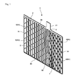
Fig. 1 depicts a perspective view showing a lead-acid storage battery grid of an embodiment. -
Fig. 2 depicts a plan view showing the lead-acid storage battery grid of the embodiment. -
Fig. 3 depicts a partly enlarged view showing the lead-acid storage battery grid of the embodiment. -
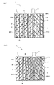
Fig. 4 depicts a plan view showing a first modification of the lead-acid storage battery grid. -
Fig. 5 depicts a plan view showing a second modification of the lead-acid storage battery grid. -
Fig. 6 depicts a plan view showing a third modification of the lead-acid storage battery grid. -
Fig. 7 depicts a plan view showing a fourth modification of the lead-acid storage battery grid. -
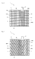
Fig. 8 depicts a plan view showing a fifth modification of the lead-acid storage battery grid. -
Fig. 9 depicts a plan view showing a sixth modification of the lead-acid storage battery grid. -
Fig. 10 depicts a plan view showing a seventh modification of the lead-acid storage battery grid. - A description will be given below of an embodiment of a storage battery grid according to the present invention with reference to the attached drawings. In the present embodiment, explanation will be made by way of a grid for use in a lead-acid storage battery. Vertical and lateral directions on sheets of
Fig. 1 andFig. 2 are defined as vertical and lateral directions in the description. - A
grid 1 in the present embodiment is used as one member of a positive plate or a negative plate in an electrode group serving as a power generating element for a lead-acid storage battery. In the case where thegrid 1 is used for the positive plate, thegrid 1 is filled with a positive active material (i.e., lead dioxide). In contrast, in the case where thegrid 1 is used for the negative plate, thegrid 1 is filled with a negative active material (i.e., spongy lead). - Specifically, the
grid 1 is obtained by blanking a rolled sheet made of a lead alloy. As shown inFigs. 1 and2 , thegrid 1 includes aframe bone 2 formed into a substantially rectangular shape, alug portion 21 projecting from anupper side 2a (i.e., a first side portion) of theframe bone 2 upward outside of a frame, a plurality ofvertical bones 3 vertically extending in a linear manner inside of theframe bone 2, and a plurality ofslanted bones 4 slantwise formed inside of theframe bone 2. Thegrid 1 in the present embodiment is devoid of a lateral bone substantially parallel to theupper side 2a of theframe bone 2. - Specifically, the
grid 1 includes, out of the plurality ofvertical bones 3, a mainvertical bone 3X (i.e., a main bone) formed of one or more vertical bones 3 (three in the present embodiment) extending downward from right under aconnection portion 5 to thelug portion 21 at theupper side 2a. The mainvertical bone 3X is substantially perpendicular to theupper side 2a of theframe bone 2 and alower side 2b (i.e., a second side portion) opposite to theupper side 2a, and is tapered with a gradually reduced width from the upper section to the lower section, as viewed on a plane. This can make the shape of a vertical bone most suitable for collected electric power. Since a width dimension is smaller at the lower section, a material of an electrode plate can be reduced. - The plurality of vertical bones 3 (i.e., sub-bones) arranged on right and left sides of the main
vertical bone 3X are arranged at intervals in the lateral direction (i.e., the extending direction) of theupper side 2a, and they are formed such that the intervals become greater as they are more apart from the mainvertical bone 3X toward the right and left sides. The plurality ofvertical bones 3 arranged on the right and left sides of the mainvertical bone 3X are configured such that the width of each of them becomes smaller as they are more apart from the mainvertical bone 3X. This can make the interval between thevertical bones 3 most suitable for collected electric power. Other than that, the plurality ofvertical bones 3 may be configured such that the width of each of them becomes smaller as they are more apart from the mainvertical bone 3X. - The plurality of
slanted bones 4 include at leastslanted bones 4 extending slantwise downward from the mainvertical bone 3X in a linear manner. In other words, the plurality ofslanted bones 4 include: a plurality of slanted bones 4 (4m) branched from the mainvertical bone 3X and extending slantwise downward; and a plurality of slanted bones 4 (4n) branched from theupper side 2a of theframe bone 2 and extending slantwise downward. Some (two in the present embodiment) of the slantedbones 4 are branched from theconnection portion 5 to thelug portion 21 at theupper side 2a. Thus, the upper ends of the slantedbones 4 are connected to the mainvertical bone 3X or theupper side 2a of theframe bone 2; the lower ends of the slantedbones 4 are connected to thesides lower side 2b of theframe bone 2. In other words, the lower ends of the slantedbones 4 extend to reach theframe bone 2. - The plurality of
slanted bones 4 are formed into a substantially inverted V shape from the mainvertical bone 3X, as viewed on a plane, and therefore, they are branched from at least the mainvertical bone 3X rightward and leftward of the mainvertical bone 3X, and further, extend slantwise from theupper side 2a to thelower side 2b. Specifically, the plurality ofslanted bones 4 are formed into a substantially linear manner in which they are inclined upward near the mainvertical bone 3X, as viewed on a plane. Here, a space defined by the mainvertical bone 3X and the like is formed into a substantially quadrilateral shape. In this manner, since the slantedbones 4 are substantially linear, the channel of a current generated on the right and left sides of the mainvertical bone 3X becomes linear, thereby shortening the channel of a current to the mainvertical bone 3X or theupper side 2a. - Specifically, the plurality of
slanted bones 4 formed on the left side of the mainvertical bone 3X are arranged with the intervals in the vertical direction (i.e., the extending direction) of the mainvertical bone 3X at an slant angle of 45° with respect to the mainvertical bone 3X, as shown inFig. 3 . The plurality ofslanted bones 4 formed on the right side of the mainvertical bone 3X are arranged with the intervals in the vertical direction of the mainvertical bone 3X at an slant angle of 45° with respect to the mainvertical bone 3X. A connection point P1 at the upper end of each of the slanted bones 4 (4m) formed on the left side and a connection point P2 at the upper end of each of the slanted bones 4 (4m) formed on the right side mate with each other in a height direction at the mainvertical bone 3X. With the above-described configuration, the slantedbones 4 formed on the left side of the mainvertical bone 3X and theslanted bones 4 formed on the right side of the mainvertical bone 3X are laterally symmetric with each other with respect to the mainvertical bone 3X. - The plurality of
slanted bones 4 formed on the left side of the mainvertical bone 3X are formed substantially in parallel to each other, and the plurality ofslanted bones 4 formed on the right side of the mainvertical bone 3X are formed substantially in parallel to each other. In this manner, the plurality ofslanted bones 4 are formed substantially in parallel to each other, and therefore, a potential distribution can be made more uniform. The interval between the adjacent slantedbones 4 may be identical to each other, may be different from each other, or may be enlarged downward. In other words, the intervals between theslanted bones 4 may be varied so as to make the potential distribution uniform. - As described above, the
grid 1 in the present embodiment includes: theframe bone 2 formed into a rectangular shape; thelug portion 21 that is connected to theupper side 2a of theframe bone 2 and projects outward from a frame; the mainvertical bone 3X that vertically extends from the connection portion between theupper side 2a and thelug portion 21 to thelower side 2b opposite to theupper side 2a, the width of the mainvertical bone 3X becoming smaller apart from thelug portion 21, as viewed on a plane; the plurality ofvertical bones 3 extending from theupper side 2a to thelower side 2b, arranged in the extending direction of theupper side 2a of theframe bone 2 with the intervals that become greater apart from the mainvertical bone 3X; and the plurality ofslanted bones 4 that are branched from at least the mainvertical bone 3X toward both sides and extend slantwise toward thelower side 2b at the slant angle from 5° to 60°. The plurality ofslanted bones 4 are arranged with the intervals in the extending direction of the mainvertical bone 3X. Some of the slantedbones 4 are branched from theupper side 2a of theframe bone 2, and further, some of the slantedbones 4 are branched from the connection portion to thelug portion 21 at theupper side 2a of theframe bone 2. Each of the plurality of spaces defined by the mainvertical bone 3X, thevertical bone 3, and the like is at least partly formed into a substantially quadrilateral shape. Each of the plurality of spaces defined by thelower side 2b of theframe bone 2, thevertical bone 3, the slantedbone 4, and the like is partly formed into a substantially quadrilateral shape. Additionally, out of the plurality ofslanted bones 4, the intervals between the plurality ofslanted bones 4 branched from the mainvertical bone 3X become greater apart from theupper side 2a of theframe bone 2. - Next, results from potential distribution analyses carried out with respect to the
grid 1 such configured as described above and a conventional expanded grid will be shown below. The conventional expanded grid had a grid dimension [a width (mm) × a height (mm)] of 137.0 × 115.0, a grid thickness (mm) of 1.00, and a grid mass (g) of 42.0. In contrast, the lead-acid storage battery grid according to the present invention had a grid dimension [a width (mm) × a height (mm)] of 137.0 × 115.0, a grid thickness (mm) of 0.80, and a grid mass (g) of 42.0. A current of 1 A was made to flow at the upper end of the lug portion in each of the conventional expanded grid and the lead-acid storage battery grid according to the present invention, followed by a potential distribution analysis. - The rate of a potential drop (i.e., a voltage drop) with reference (0V) to a lower frame of the conventional expanded grid is assumed as 100%. In the case where the slant angle of the slanted bone of the lead-acid storage battery grid according to the present invention is varied from 0° to 80°, the rate of a potential drop with reference (0V) to the lower side of the lead-acid storage battery grid according to the present invention and the uniformity of a potential distribution are shown in Table 1.
[Table 1] GRID SLANT ANGLE OF SLANTED BONE RATE OF POTENTIAL DROP OF GRID (%) UNIFORMITY OF POTENTIAL DISTRIBUTION OVER ENTIRE GRID REMARKS CONVENTIONAL EXPANDED GRID - 100 × PRIOR ART LEAD-ACID STORAGE BATTERY GRID ACCORDING TO PRESENT INVENTION 0 50 ○ COMPARATIVE EXAMPLE 5 48 ⊙ EXAMPLE 15 48 ⊙ EXAMPLE 25 48 ⊙ EXAMPLE 30 48 ⊙ EXAMPLE 35 48 ⊙ EXAMPLE 45 48 ⊙ EXAMPLE 60 49 ⊙ EXAMPLE 80 50 ○ COMPARATIVE EXAMPLE * UNIFORMITY OF POTENTIAL DISTRIBUTION ... ⊙: EXCELLENT, ○: GOOD, ×: BAD - The rate of the potential drop of the lead-acid storage battery grid according to the present invention was decreased down to 48% to 50% of that of the conventional expanded grid. The uniformity of the potential distribution of the lead-acid storage battery grid according to the present invention was ⊙ or ○ (excellent or good), that is, it was more excellent than that of the conventional expanded grid since the uniformity of the potential distribution of the conventional expanded grid was × (bad). In view of this, it was found that the potential distribution of the entire lead-acid storage battery grid according to the present invention was made to be uniform in comparison with that of the conventional expanded grid. The uniformity of the potential distribution of the entire grid when the slant angle of the slanted bone of the lead-acid storage battery grid according to the present invention ranged from 0° to 80° was ○ (good), and further, the uniformity of the potential distribution when the slant angle of the slanted bone of the lead-acid storage battery grid according to the present invention ranged from 5° to 60° was ⊙ (excellent). It was found from the results that the potential distribution was made to be more uniform within the range from 5° to 60° of the slant angle of the slanted bone of the lead-acid storage battery grid according to the present invention.
- In this manner, the use of the lead-acid storage battery grid according to the present invention for a lead-acid storage battery can enhance a high rate discharge performance (a cold cranking current and a low temperature high rate discharge performance) more than the use of the conventional expanded grid when it has almost the same lead mass as that of the conventional expanded grid. In the meantime, when an electrode plate for a lead-acid storage battery according to the present invention is used for a lead-acid storage battery, substantially the same high rate discharge performance (a cold cranking current and a low temperature high rate discharge performance) as that of the conventional expanded grid can be achieved by an electrode plate having a smaller lead mass.
- The results of elongation analyses carried out with respect to the above-described conventional expanded grid and the above-described lead-acid storage battery grid according to the present invention are shown in Table 2.
[Table 2] GRID SLANT ANGLE OF SLANTED BONE RATE OF GRID ELONGATION (%) REMARKS WIDTH DIRECTION (LATERAL DIRECTION) HEIGHT DIRECTION (VERTICAL DIRECTION) CONVENTIONAL EXPANDED GRID - 100 100 PRIOR ART LEAD-ACID STORAGE BATTERY GRID ACCORDING TO PRESENT INVENTION 0 50 57 COMPARATIVE EXAMPLE 5 50 57 EXAMPLE 15 50 57 EXAMPLE 25 60 57 EXAMPLE 30 70 43 EXAMPLE 35 80 43 EXAMPLE 45 80 43 EXAMPLE 60 50 43 EXAMPLE 80 50 43 COMPARATIVE EXAMPLE - Assuming that each of the rate of a grid elongation in the width direction (i.e., the lateral direction) of the conventional expanded grid and the rate of a grid elongation in the height direction (i.e., the vertical direction) of the conventional expanded grid was set to 100%, the rate of a grid elongation in the width direction in the lead-acid storage battery grid according to the present invention ranged from 50% to 80% of that of the conventional expanded grid whereas the rate of a grid elongation in the height direction ranged from 43% to 57%: namely, they were decreased. In view of these, it was found that the grid elongation in each of the width direction and the height direction was decreased in the lead-acid storage battery grid according to the present invention. Consequently, the cycle life performance of the lead-acid storage battery using the grid according to the present invention can be enhanced, for example, the number of cycles in a cycle life test at an ambient temperature of 75° pursuant to the light load lifetime test determined by JIS 5301 is increased.
- With the
grid 1 according to the present embodiment such configured as described above, the mainvertical bone 3X is disposed under thelug portion 21, and therefore, the distance between thelug portion 21 and thelower side 2b of theframe bone 2 can be shortened. The plurality ofslanted bones 4 extend slantwise downward from at least the mainvertical bone 3X, and therefore, the channel for a current generated at the sides of the mainvertical bone 3X toward the mainvertical bone 3X or thelug portion 21 can be shortened. Additionally, the plurality ofslanted bones 4 are formed into the substantially inverted V shape on the mainvertical bone 3X, as viewed on a plane, and therefore, the channels for currents generated on the right and left sides of the mainvertical bone 3X toward the mainvertical bone 3X or thelug portion 21 can be shortened. Furthermore, the space defined by the mainvertical bone 3X and theslanted bones 4 is formed into the substantially quadrilateral shape, thereby reducing bypass channels remote from thelug portion 2 in comparison with a triangular shape. Consequently, in theentire grid 1, an electric resistance can be decreased and the potential distribution of the electrode plate can be made uniform. In addition, theframe bone 2 is formed into the substantially rectangular shape, thus enhancing a mechanical strength. - The
grid 1 of the present embodiment includes the plurality ofvertical bones 3 and the plurality ofslanted bones 4 but is devoid of the lateral bone substantially parallel to theupper side 2a of theframe bone 2. Therefore, the channel of the current generated on the right and left sides of the mainvertical bone 3X includes only the upward channel formed of thevertical bones 3 and the slantwise upward channel formed of the slantedbones 4. The channel reaching thelug portion 21 via the mainvertical bone 3X and theupper side 2a can be shortened, thus reducing the electric resistance. - Since the
grid 1 is formed by blanking, the thickness of the grid can be further reduced (that is, the mass of the grid can be further reduced) in comparison with the case where the grid is formed by casting. As a consequence, the material of the grid is reduced, thus reducing a cost. A difference in thickness of the grid is caused by a difference in corrosion mode due to a difference in metallic tissue. In general, a cast grid has a large crystalline grain. Corrosion proceeds in such a manner as to enter a crystalline grain field, and therefore, the cast grid has characteristics of a small corrosion ratio at which the grid is broken. In contrast, the punched grid manufactured by blanking a rolled sheet is rolled after the fabrication of a slab, so that a large crystalline grain contained in the slab is elongated in a roll direction. In this manner, there is no crystalline grain field that may break the grid, and thus, corrosion sequentially proceeds from the grid surface. With these characteristics, the punched grid manufactured with the rolling sheet can be reduced in grid thickness in comparison with the cast grid. - The
grid 1 is manufactured by blanking or casting in the following manner. A rectangular frame bone is formed. A lug portion is formed in such a manner as to be connected to a first side portion of the frame bone and project outward of a frame. A main bone is formed in such a manner as to extend from a connection portion to the lug portion at the first side portion to a second side portion opposite to the first side portion. A sub-bone is formed in such a manner as to extend from the first side portion to the second side portion. A plurality of slanted bones are formed in such a manner as to be branched from at least the main bone toward both sides and slantwise extend toward the second side portion. The plurality of slanted bones are arranged at intervals in the extending direction of the main bone. Each of a plurality of spaces defined by the main bone, the sub-bones, and the like is at least partly formed into a substantially quadrilateral shape. - Incidentally, the present invention is not limited to the above-described embodiment.
- For example, in the above-described embodiment, the main
vertical bone 3X is formed of onevertical bone 3, and the plurality ofslanted bones 4 extend from the mainvertical bone 3X. However, a mainvertical bone 3X may be formed of a plurality of vertical bones 3 (two inFig. 4 ), and a plurality ofslanted bones 4 may extend from the plurality of mainvertical bones 3X, as shown inFig. 4 . - Furthermore, as shown in
Fig. 5 , anupper side 2a of aframe bone 2 may be increased in height toward alug portion 21, as viewed on a plane. Specifically, the lower surface of theupper side 2a of theframe bone 2 is formed into a substantially V shape inclined downward toward thelug portion 21 from both ends thereof. Consequently, the mechanical strength of agrid 1 can be enhanced, and further, a potential distribution of an electrode plate can be made more uniform. - Not only a main
vertical bone 3X but also othervertical bones 3 may be decreased in width from the upper section to the lower section.Fig. 5 shows a case where threevertical bones 3 on right and left sides of the mainvertical bone 3X are decreased in width from the upper section to the lower section. - The slant angle (e.g., 45°) of each of the plurality of
slanted bones 4 on the left side of the mainvertical bone 3X and the slant angle (e.g., 45°) of each of the plurality ofslanted bones 4 on the right side of the mainvertical bone 3X are the same in the above-described embodiment. However, the slant angles ofslanted bones 4 on right and left sides may be different from each other. Specifically, the slant angle of each of a plurality ofslanted bones 4 on the left side of the mainvertical bone 3X may be 45° whereas the slant angle of each of a plurality ofslanted bones 4 on the right side of the mainvertical bone 3X may be 60°. - Although the slant angle of each of the slanted
bones 4 is 45° in the above-described embodiment, it may be other values. As shown inFig. 6 , the slant angle of the slantedbone 4 may be 5° in a lateral direction inFig. 6 (i.e., 85° with respect to a mainvertical bone 3X). As shown inFig. 7 , the slant angle may be 60° (i.e., 30° with respect to a mainvertical bone 3X). - Although the connection portions of the slanted
bones 4 on the right and left sides are the same as each other in the height direction in the above-described embodiment, they may be shifted from each other in a height direction, as shown inFigs. 8 and 9 . - Although all of the slanted
bones 4 are connected to thelower side 2b orside frame bone 2 in the above-described embodiment, some of the slantedbones 4 may not be connected to thelower side 2b orside frame bone 2. For example, as shown inFig. 10 , out of a plurality ofslanted bones 4, the slantedbones 4 that cross aside frame bone 2 when linearly extending are connected to theside slanted bones 4, the slantedbones 4 that cross alower side 2b of theframe bone 2 when linearly extending are connected to thevertical bone 3 immediately before or more beforehand of thelower side 2b, and further, anend 4e of the slantedbone 4 is formed at thevertical bone 3 immediately before or more beforehand of thelower side 2b. In this case, each of a plurality of spaces defined by thelower side 2b and the like is formed into a substantially quadrilateral shape. The slant angles of a plurality of slantedbones 4m branched from the mainvertical bone 3X with respect to the mainvertical bone 3X become greater apart from theupper side 2a of theframe bone 2. In the grid shown inFig. 10 , the slant angle of the slantedbone 4m nearest theupper side 2a is 30° (i.e., 60° with respect to the mainvertical bone 3X), and further, the slant angle of the remotest slantedbone 4m is 20° (i.e., 70° with respect to the mainvertical bone 3X). In this manner, the optimum slant angle of the slantedbone 4m can be set depending on collected electric power. Thus, the potential distribution of thegrid 1 can be made more uniform, and the workability for filling the grid with the active material can be enhanced. - Although the grid includes the plurality of slanted bones 4 (4m) slantwise extending downward from the main
vertical bone 3X and the plurality of slanted bones 4 (4n) slantwise extending downward from theupper side 2a of theframe bone 2 in the above-described embodiment, the grid may be devoid of slanted bones 4 (4n) slantwise extending downward from theupper side 2a. - Although the grid used for a lead-acid storage battery is exemplified in the above-described embodiment, the present invention is not limited to this. For example, the grid according to the present invention is applicable to a grid filled with an active material for a nickel-metal hydride battery and the like.
- Although the
grid 1 is formed by blanking in the above-described embodiment, it may be formed by casting. - Although the grid in the above-described embodiment includes the upper side out of the four sides of the frame bone as the first side portion and the lower side as the second side portion, one of the right and left sides out of the four sides of the frame bone may be used as a first side portion whereas the other may be used as a second side portion.
- The present invention is not limited to the above-described embodiment, and it may be variously modified without departing from the scope.
-
- 1
- grid
- 2
- frame bone
- 2a
- upper side
- 2b
- lower side
- 21
- lug portion
- 3
- vertical bone
- 3X
- main vertical bone
- 4
- slanted bone
- 5
- connection portion
Claims (16)
- A storage battery grid comprising:a frame bone that includes a substantially rectangular shape;a lug portion that is connected to a first side portion of the frame bone and projects outwardly from the frame bone;a main bone that extends from a connection portion of the first side portion, to which the lug portion is connected, to a second side portion which is opposed to the first side portion;a sub-bone that extends from the first side portion to the second side portion; anda plurality of slanted bones that extend obliquely toward the second side portion, at least the plurality of slanted bones branching from the main bone toward both sides,wherein the plurality of slanted bones are arranged at intervals in a direction in which the main bone extends, andat least part of a plurality of spaces, which are defined by the main bone and the sub-bone that are partially forming sides of the spaces, include a substantially quadrilateral shape.
- The storage battery grid according to claim 1, wherein part of the plurality of slanted bones branches from the first side portion of the frame bone.
- The storage battery grid according to claim 1 or 2, wherein part of the plurality of slanted bones branches from the connection portion, to which the lug portion is connected in the first side portion of the frame bone.
- The storage battery grid according to any one of claims 1 to 3, wherein the sub-bone comprises a plurality of sub-bones arranged at intervals in a direction in which the first side portion extends, and
the intervals of the sub-bones increase in a direction away from the main bone. - The storage battery grid according to claim 4, wherein a plurality of spaces, which are defined by the second side portion, the sub-bone and the slanted bone that are partially forming sides of the spaces, include a substantially quadrilateral shape.
- The storage battery grid according to any one of claims 1 to 5, wherein the main bone is arranged perpendicularly to the first side portion and the second side portion.
- The storage battery grid according to any one of claims 1 to 6, wherein the grid is devoid of a lateral bone that is substantially parallel to the first side portion of the frame bone.
- The storage battery grid according to any one of claims 1 to 7, wherein intervals of the slanted bones, which are part of the plurality of slanted bones and branching from the main bone, increase as the slanted bones extend away from the first side portion.
- The storage battery grid according to any one of claims 1 to 8, wherein a slant angle of the slanted bones relative to the main bone increases as the slanted bones extend away from the first side portion, the slanted bones being part of the plurality of slanted bones and branching from the main bone.
- The storage battery grid according to any one of claims 1 to 9, wherein a slant angle of the plurality of slanted bones is in a range from 5 degrees to 60 degrees.
- The storage battery grid according to any one of claims 1 to 10, wherein a width of the main bone in a plan view decreases as it extends away from the lug portion.
- The storage battery grid according to any one of claims 1 to 11, wherein a width of the first side portion in a plan view increases as it approaches to the lug portion.
- A storage battery comprising the storage battery grid according to any one of claims 1 to 12.
- The storage battery according to claim 13, wherein the storage battery grid is made from a lead alloy.
- The storage battery according to claim 13 or 14, wherein the storage battery grid is formed by blanking.
- A method of manufacturing a storage battery grid comprising:forming a frame bone that includes a substantially rectangular shape;forming a lug portion that is connected to a first side portion of the frame bone and projects outwardly from the frame bone;forming a main bone that extends from a connection portion of the first side portion, to which the lug portion is connected, to a second side portion which is opposed to the first side portion;forming a sub-bone that extends from the first side portion to the second side portion;forming a plurality of slanted bones that extend obliquely toward the second side portion, at least the plurality of slanted bones branching from the main bone toward both sides;arranging the plurality of slanted bones at intervals in a direction in which the main bone extends; andcausing at least part of a plurality of spaces, which are defined by the main bone and the sub-bone that are partially forming sides of the spaces, to include a substantially quadrilateral shape.
Applications Claiming Priority (2)
| Application Number | Priority Date | Filing Date | Title |
|---|---|---|---|
| JP2012198408 | 2012-09-10 | ||
| PCT/JP2013/004464 WO2014038123A1 (en) | 2012-09-10 | 2013-07-23 | Lattice for storage battery, method for producing lattice for storage battery, and storage battery using lattice for storage battery |
Publications (3)
| Publication Number | Publication Date |
|---|---|
| EP2747179A1 true EP2747179A1 (en) | 2014-06-25 |
| EP2747179A4 EP2747179A4 (en) | 2015-04-29 |
| EP2747179B1 EP2747179B1 (en) | 2017-09-27 |
Family
ID=50236762
Family Applications (1)
| Application Number | Title | Priority Date | Filing Date |
|---|---|---|---|
| EP13835776.9A Active EP2747179B1 (en) | 2012-09-10 | 2013-07-23 | Lattice for storage battery, method for producing lattice for storage battery, and storage battery using lattice for storage battery |
Country Status (5)
| Country | Link |
|---|---|
| US (1) | US20140212764A1 (en) |
| EP (1) | EP2747179B1 (en) |
| JP (2) | JP5729518B2 (en) |
| CN (1) | CN103959521A (en) |
| WO (1) | WO2014038123A1 (en) |
Cited By (1)
| Publication number | Priority date | Publication date | Assignee | Title |
|---|---|---|---|---|
| EP2808928A1 (en) * | 2013-05-31 | 2014-12-03 | GS Yuasa International Ltd. | Storage battery grid, method of manufacturing storage battery grid, and storage battery using storage battery grid |
Families Citing this family (13)
| Publication number | Priority date | Publication date | Assignee | Title |
|---|---|---|---|---|
| JP6503634B2 (en) * | 2014-05-07 | 2019-04-24 | 株式会社Gsユアサ | Lattice for lead storage battery and lead storage battery using the same |
| HU230572B1 (en) * | 2014-05-20 | 2016-12-28 | Andrew Sárosi George | Form of accumulator grid, accumulator cell and accumulator from produced accumulator grid |
| CN119315041A (en) | 2017-01-27 | 2025-01-14 | Cps科技控股有限公司 | Battery grid |
| KR20200014317A (en) | 2017-06-09 | 2020-02-10 | 씨피에스 테크놀로지 홀딩스 엘엘씨 | Lead acid battery |
| US11936032B2 (en) | 2017-06-09 | 2024-03-19 | Cps Technology Holdings Llc | Absorbent glass mat battery |
| JP6988248B2 (en) * | 2017-08-09 | 2022-01-05 | 株式会社Gsユアサ | Lattice for lead-acid batteries and lead-acid batteries |
| EP3855537A4 (en) * | 2018-10-16 | 2022-08-03 | GS Yuasa International Ltd. | LEAD ACCUMULATOR |
| JP7463719B2 (en) * | 2019-12-25 | 2024-04-09 | 株式会社Gsユアサ | Battery collectors and electrode plates |
| JP6998441B2 (en) * | 2020-01-08 | 2022-02-04 | 古河電池株式会社 | Liquid lead-acid battery |
| JP6998442B2 (en) * | 2020-01-08 | 2022-01-18 | 古河電池株式会社 | Liquid lead-acid battery |
| USD964284S1 (en) | 2021-01-21 | 2022-09-20 | Gs Yuasa International Ltd. | Grid base plate for lead storage battery |
| USD964283S1 (en) | 2021-01-21 | 2022-09-20 | Gs Yuasa International Ltd. | Grid base plate for lead storage battery |
| USD964285S1 (en) | 2021-01-21 | 2022-09-20 | Gs Yuasa International Ltd. | Grid base plate for lead storage battery |
Family Cites Families (22)
| Publication number | Priority date | Publication date | Assignee | Title |
|---|---|---|---|---|
| US1515279A (en) * | 1923-05-11 | 1924-11-11 | Sato Junjiro | Storage battery |
| JPS5140606B1 (en) * | 1970-11-12 | 1976-11-05 | ||
| IT952792B (en) * | 1971-04-29 | 1973-07-30 | Lucas Industries Ltd | METHOD OF MANUFACTURING GRIDS FOR BATTERY PLATES |
| JPS5115120A (en) * | 1974-07-30 | 1976-02-06 | Shin Kobe Electric Machinery | NAMARICHIKU DENCHOKIBAN |
| JPS6020593B2 (en) * | 1974-08-09 | 1985-05-22 | テイ−、ア−ル、ダブリユ−、インコーポレーテツド | Expansion chamber pump |
| JPS5161225U (en) * | 1974-12-16 | 1976-05-14 | ||
| US3989539A (en) * | 1975-12-01 | 1976-11-02 | Varta Batteries Ltd. | Battery grid |
| JPS5456132U (en) * | 1977-09-27 | 1979-04-18 | ||
| JPS615724Y2 (en) * | 1977-09-27 | 1986-02-21 | ||
| JPS55104261U (en) * | 1979-01-17 | 1980-07-21 | ||
| US4221852A (en) * | 1979-05-21 | 1980-09-09 | Esb United States, Inc. | Radial grids for lead acid batteries |
| DE3234342C2 (en) * | 1982-09-16 | 1985-05-30 | Accumulatorenfabrik Sonnenschein GmbH, 6470 Büdingen | Electrode grids for accumulators |
| JPS6393068U (en) * | 1986-12-08 | 1988-06-16 | ||
| JPH082921Y2 (en) | 1989-10-23 | 1996-01-29 | 古河電池株式会社 | Substrate for storage battery electrode |
| JPH07320743A (en) | 1994-05-19 | 1995-12-08 | Japan Storage Battery Co Ltd | Lead plate for lead acid battery |
| US5601953A (en) * | 1994-05-26 | 1997-02-11 | Venture Enterprises, Incorporated | Battery grids |
| JPH1154115A (en) * | 1997-08-04 | 1999-02-26 | Japan Storage Battery Co Ltd | Plate for lead-acid battery |
| US6953641B2 (en) * | 2001-01-05 | 2005-10-11 | Johnson Controls Technology Company | Battery grid |
| JP2004119023A (en) * | 2002-09-24 | 2004-04-15 | Shin Kobe Electric Mach Co Ltd | Lead storage battery |
| JP2004213951A (en) * | 2002-12-27 | 2004-07-29 | Ntt Power & Building Facilities Inc | Lead-acid battery |
| CN2667676Y (en) * | 2003-12-11 | 2004-12-29 | 邱延甫 | Leaf vein shape positive pole plate grid without maintenance |
| CN201616473U (en) * | 2010-01-08 | 2010-10-27 | 超威电源有限公司 | Power type medium and large density battery grid |
-
2013
- 2013-07-23 EP EP13835776.9A patent/EP2747179B1/en active Active
- 2013-07-23 JP JP2014505421A patent/JP5729518B2/en active Active
- 2013-07-23 CN CN201380003588.XA patent/CN103959521A/en active Pending
- 2013-07-23 US US14/350,386 patent/US20140212764A1/en not_active Abandoned
- 2013-07-23 WO PCT/JP2013/004464 patent/WO2014038123A1/en not_active Ceased
-
2014
- 2014-11-11 JP JP2014229140A patent/JP2015053284A/en active Pending
Cited By (2)
| Publication number | Priority date | Publication date | Assignee | Title |
|---|---|---|---|---|
| EP2808928A1 (en) * | 2013-05-31 | 2014-12-03 | GS Yuasa International Ltd. | Storage battery grid, method of manufacturing storage battery grid, and storage battery using storage battery grid |
| US9825303B2 (en) | 2013-05-31 | 2017-11-21 | Gs Yuasa International Ltd. | Storage battery grid, method of manufacturing storage battery grid, and storage battery using storage battery grid |
Also Published As
| Publication number | Publication date |
|---|---|
| EP2747179B1 (en) | 2017-09-27 |
| JPWO2014038123A1 (en) | 2016-08-08 |
| JP5729518B2 (en) | 2015-06-03 |
| JP2015053284A (en) | 2015-03-19 |
| US20140212764A1 (en) | 2014-07-31 |
| EP2747179A4 (en) | 2015-04-29 |
| WO2014038123A1 (en) | 2014-03-13 |
| CN103959521A (en) | 2014-07-30 |
Similar Documents
| Publication | Publication Date | Title |
|---|---|---|
| EP2747179B1 (en) | Lattice for storage battery, method for producing lattice for storage battery, and storage battery using lattice for storage battery | |
| EP2808928B1 (en) | Storage battery grid, method of manufacturing storage battery grid, and storage battery using storage battery grid | |
| US8399135B2 (en) | Battery grid | |
| US9577266B2 (en) | Negative grid for battery | |
| JP6456537B1 (en) | Positive electrode grid for lead acid battery and lead acid battery | |
| KR101212864B1 (en) | Battery pack | |
| JP2019153384A (en) | Positive electrode grid body for lead acid battery and lead acid battery | |
| CN215869408U (en) | Grid line electrode of solar cell and solar cell | |
| US20160013344A1 (en) | Method to assemble a rectangular cic from a circular wafer | |
| US6793691B2 (en) | Method for assembling battery element group and battery manufactured with the same method | |
| EP3203572A1 (en) | Positive electrode plate for lead-acid battery, lead-acid battery and method of manufacturing positive electrode plate for lead-acid battery | |
| US10522818B2 (en) | Three-dimensional electrode structure and secondary battery including the same | |
| CN112332031B (en) | Connecting element for electrical contact and method for producing a connecting element | |
| JP2019153386A (en) | Positive electrode lattice structure for lead acid battery and lead acid battery | |
| JP5048008B2 (en) | Lattice substrate for lead acid battery | |
| JP7024177B2 (en) | Lead-acid battery and current collector | |
| US20100021791A1 (en) | Asymmetric dovetail interconnect for solid oxide fuel cell | |
| CN223898313U (en) | A wide tab grid for high-rate batteries | |
| CN217589319U (en) | Conductive plate for storage battery | |
| RU2299498C2 (en) | Current lead for lead-acid battery electrode | |
| JP2002222662A (en) | Lead storage battery | |
| CN101345311A (en) | Slab lattice of accumulator | |
| JP5092183B2 (en) | Lead acid battery | |
| KR20130089469A (en) | Structure for increase cross-sectional area of lug-joint-part on anode of secondary battery | |
| JP2004253204A (en) | Lead storage battery |
Legal Events
| Date | Code | Title | Description |
|---|---|---|---|
| PUAI | Public reference made under article 153(3) epc to a published international application that has entered the european phase |
Free format text: ORIGINAL CODE: 0009012 |
|
| 17P | Request for examination filed |
Effective date: 20140317 |
|
| AK | Designated contracting states |
Kind code of ref document: A1 Designated state(s): AL AT BE BG CH CY CZ DE DK EE ES FI FR GB GR HR HU IE IS IT LI LT LU LV MC MK MT NL NO PL PT RO RS SE SI SK SM TR |
|
| RA4 | Supplementary search report drawn up and despatched (corrected) |
Effective date: 20150330 |
|
| RIC1 | Information provided on ipc code assigned before grant |
Ipc: H01M 4/73 20060101AFI20150323BHEP Ipc: H01M 4/82 20060101ALI20150323BHEP Ipc: H01M 4/68 20060101ALI20150323BHEP Ipc: H01M 4/74 20060101ALI20150323BHEP Ipc: H01M 10/06 20060101ALI20150323BHEP |
|
| RIN1 | Information on inventor provided before grant (corrected) |
Inventor name: SAITO, KAZUMA Inventor name: NOUZUKA, KIYOSHI Inventor name: IWASAKI, SHOTA Inventor name: FUJITA, KOHEI Inventor name: ISHIGURO, HIROYUKI Inventor name: NISHIZAWA, JUNICHI |
|
| DAX | Request for extension of the european patent (deleted) | ||
| 17Q | First examination report despatched |
Effective date: 20160128 |
|
| STAA | Information on the status of an ep patent application or granted ep patent |
Free format text: STATUS: EXAMINATION IS IN PROGRESS |
|
| GRAP | Despatch of communication of intention to grant a patent |
Free format text: ORIGINAL CODE: EPIDOSNIGR1 |
|
| STAA | Information on the status of an ep patent application or granted ep patent |
Free format text: STATUS: GRANT OF PATENT IS INTENDED |
|
| INTG | Intention to grant announced |
Effective date: 20170421 |
|
| GRAS | Grant fee paid |
Free format text: ORIGINAL CODE: EPIDOSNIGR3 |
|
| GRAA | (expected) grant |
Free format text: ORIGINAL CODE: 0009210 |
|
| STAA | Information on the status of an ep patent application or granted ep patent |
Free format text: STATUS: THE PATENT HAS BEEN GRANTED |
|
| AK | Designated contracting states |
Kind code of ref document: B1 Designated state(s): AL AT BE BG CH CY CZ DE DK EE ES FI FR GB GR HR HU IE IS IT LI LT LU LV MC MK MT NL NO PL PT RO RS SE SI SK SM TR |
|
| REG | Reference to a national code |
Ref country code: GB Ref legal event code: FG4D |
|
| REG | Reference to a national code |
Ref country code: CH Ref legal event code: EP |
|
| REG | Reference to a national code |
Ref country code: AT Ref legal event code: REF Ref document number: 932787 Country of ref document: AT Kind code of ref document: T Effective date: 20171015 |
|
| REG | Reference to a national code |
Ref country code: IE Ref legal event code: FG4D |
|
| REG | Reference to a national code |
Ref country code: DE Ref legal event code: R096 Ref document number: 602013027284 Country of ref document: DE |
|
| PG25 | Lapsed in a contracting state [announced via postgrant information from national office to epo] |
Ref country code: NO Free format text: LAPSE BECAUSE OF FAILURE TO SUBMIT A TRANSLATION OF THE DESCRIPTION OR TO PAY THE FEE WITHIN THE PRESCRIBED TIME-LIMIT Effective date: 20171227 Ref country code: FI Free format text: LAPSE BECAUSE OF FAILURE TO SUBMIT A TRANSLATION OF THE DESCRIPTION OR TO PAY THE FEE WITHIN THE PRESCRIBED TIME-LIMIT Effective date: 20170927 Ref country code: LT Free format text: LAPSE BECAUSE OF FAILURE TO SUBMIT A TRANSLATION OF THE DESCRIPTION OR TO PAY THE FEE WITHIN THE PRESCRIBED TIME-LIMIT Effective date: 20170927 Ref country code: SE Free format text: LAPSE BECAUSE OF FAILURE TO SUBMIT A TRANSLATION OF THE DESCRIPTION OR TO PAY THE FEE WITHIN THE PRESCRIBED TIME-LIMIT Effective date: 20170927 Ref country code: HR Free format text: LAPSE BECAUSE OF FAILURE TO SUBMIT A TRANSLATION OF THE DESCRIPTION OR TO PAY THE FEE WITHIN THE PRESCRIBED TIME-LIMIT Effective date: 20170927 |
|
| REG | Reference to a national code |
Ref country code: NL Ref legal event code: MP Effective date: 20170927 |
|
| REG | Reference to a national code |
Ref country code: LT Ref legal event code: MG4D |
|
| REG | Reference to a national code |
Ref country code: AT Ref legal event code: MK05 Ref document number: 932787 Country of ref document: AT Kind code of ref document: T Effective date: 20170927 |
|
| PG25 | Lapsed in a contracting state [announced via postgrant information from national office to epo] |
Ref country code: RS Free format text: LAPSE BECAUSE OF FAILURE TO SUBMIT A TRANSLATION OF THE DESCRIPTION OR TO PAY THE FEE WITHIN THE PRESCRIBED TIME-LIMIT Effective date: 20170927 Ref country code: LV Free format text: LAPSE BECAUSE OF FAILURE TO SUBMIT A TRANSLATION OF THE DESCRIPTION OR TO PAY THE FEE WITHIN THE PRESCRIBED TIME-LIMIT Effective date: 20170927 Ref country code: BG Free format text: LAPSE BECAUSE OF FAILURE TO SUBMIT A TRANSLATION OF THE DESCRIPTION OR TO PAY THE FEE WITHIN THE PRESCRIBED TIME-LIMIT Effective date: 20171227 Ref country code: GR Free format text: LAPSE BECAUSE OF FAILURE TO SUBMIT A TRANSLATION OF THE DESCRIPTION OR TO PAY THE FEE WITHIN THE PRESCRIBED TIME-LIMIT Effective date: 20171228 |
|
| PG25 | Lapsed in a contracting state [announced via postgrant information from national office to epo] |
Ref country code: NL Free format text: LAPSE BECAUSE OF FAILURE TO SUBMIT A TRANSLATION OF THE DESCRIPTION OR TO PAY THE FEE WITHIN THE PRESCRIBED TIME-LIMIT Effective date: 20170927 |
|
| PG25 | Lapsed in a contracting state [announced via postgrant information from national office to epo] |
Ref country code: RO Free format text: LAPSE BECAUSE OF FAILURE TO SUBMIT A TRANSLATION OF THE DESCRIPTION OR TO PAY THE FEE WITHIN THE PRESCRIBED TIME-LIMIT Effective date: 20170927 Ref country code: ES Free format text: LAPSE BECAUSE OF FAILURE TO SUBMIT A TRANSLATION OF THE DESCRIPTION OR TO PAY THE FEE WITHIN THE PRESCRIBED TIME-LIMIT Effective date: 20170927 Ref country code: CZ Free format text: LAPSE BECAUSE OF FAILURE TO SUBMIT A TRANSLATION OF THE DESCRIPTION OR TO PAY THE FEE WITHIN THE PRESCRIBED TIME-LIMIT Effective date: 20170927 |
|
| PG25 | Lapsed in a contracting state [announced via postgrant information from national office to epo] |
Ref country code: IT Free format text: LAPSE BECAUSE OF FAILURE TO SUBMIT A TRANSLATION OF THE DESCRIPTION OR TO PAY THE FEE WITHIN THE PRESCRIBED TIME-LIMIT Effective date: 20170927 Ref country code: IS Free format text: LAPSE BECAUSE OF FAILURE TO SUBMIT A TRANSLATION OF THE DESCRIPTION OR TO PAY THE FEE WITHIN THE PRESCRIBED TIME-LIMIT Effective date: 20180127 Ref country code: SM Free format text: LAPSE BECAUSE OF FAILURE TO SUBMIT A TRANSLATION OF THE DESCRIPTION OR TO PAY THE FEE WITHIN THE PRESCRIBED TIME-LIMIT Effective date: 20170927 Ref country code: SK Free format text: LAPSE BECAUSE OF FAILURE TO SUBMIT A TRANSLATION OF THE DESCRIPTION OR TO PAY THE FEE WITHIN THE PRESCRIBED TIME-LIMIT Effective date: 20170927 Ref country code: AT Free format text: LAPSE BECAUSE OF FAILURE TO SUBMIT A TRANSLATION OF THE DESCRIPTION OR TO PAY THE FEE WITHIN THE PRESCRIBED TIME-LIMIT Effective date: 20170927 Ref country code: EE Free format text: LAPSE BECAUSE OF FAILURE TO SUBMIT A TRANSLATION OF THE DESCRIPTION OR TO PAY THE FEE WITHIN THE PRESCRIBED TIME-LIMIT Effective date: 20170927 |
|
| REG | Reference to a national code |
Ref country code: FR Ref legal event code: PLFP Year of fee payment: 6 |
|
| REG | Reference to a national code |
Ref country code: DE Ref legal event code: R097 Ref document number: 602013027284 Country of ref document: DE |
|
| PG25 | Lapsed in a contracting state [announced via postgrant information from national office to epo] |
Ref country code: DK Free format text: LAPSE BECAUSE OF FAILURE TO SUBMIT A TRANSLATION OF THE DESCRIPTION OR TO PAY THE FEE WITHIN THE PRESCRIBED TIME-LIMIT Effective date: 20170927 |
|
| PLBE | No opposition filed within time limit |
Free format text: ORIGINAL CODE: 0009261 |
|
| STAA | Information on the status of an ep patent application or granted ep patent |
Free format text: STATUS: NO OPPOSITION FILED WITHIN TIME LIMIT |
|
| PG25 | Lapsed in a contracting state [announced via postgrant information from national office to epo] |
Ref country code: PL Free format text: LAPSE BECAUSE OF FAILURE TO SUBMIT A TRANSLATION OF THE DESCRIPTION OR TO PAY THE FEE WITHIN THE PRESCRIBED TIME-LIMIT Effective date: 20170927 |
|
| 26N | No opposition filed |
Effective date: 20180628 |
|
| PG25 | Lapsed in a contracting state [announced via postgrant information from national office to epo] |
Ref country code: SI Free format text: LAPSE BECAUSE OF FAILURE TO SUBMIT A TRANSLATION OF THE DESCRIPTION OR TO PAY THE FEE WITHIN THE PRESCRIBED TIME-LIMIT Effective date: 20170927 |
|
| REG | Reference to a national code |
Ref country code: CH Ref legal event code: PL |
|
| GBPC | Gb: european patent ceased through non-payment of renewal fee |
Effective date: 20180723 |
|
| PG25 | Lapsed in a contracting state [announced via postgrant information from national office to epo] |
Ref country code: MC Free format text: LAPSE BECAUSE OF FAILURE TO SUBMIT A TRANSLATION OF THE DESCRIPTION OR TO PAY THE FEE WITHIN THE PRESCRIBED TIME-LIMIT Effective date: 20170927 Ref country code: LU Free format text: LAPSE BECAUSE OF NON-PAYMENT OF DUE FEES Effective date: 20180723 |
|
| REG | Reference to a national code |
Ref country code: BE Ref legal event code: MM Effective date: 20180731 |
|
| REG | Reference to a national code |
Ref country code: IE Ref legal event code: MM4A |
|
| PG25 | Lapsed in a contracting state [announced via postgrant information from national office to epo] |
Ref country code: GB Free format text: LAPSE BECAUSE OF NON-PAYMENT OF DUE FEES Effective date: 20180723 Ref country code: IE Free format text: LAPSE BECAUSE OF NON-PAYMENT OF DUE FEES Effective date: 20180723 Ref country code: CH Free format text: LAPSE BECAUSE OF NON-PAYMENT OF DUE FEES Effective date: 20180731 Ref country code: LI Free format text: LAPSE BECAUSE OF NON-PAYMENT OF DUE FEES Effective date: 20180731 |
|
| PG25 | Lapsed in a contracting state [announced via postgrant information from national office to epo] |
Ref country code: BE Free format text: LAPSE BECAUSE OF NON-PAYMENT OF DUE FEES Effective date: 20180731 |
|
| PG25 | Lapsed in a contracting state [announced via postgrant information from national office to epo] |
Ref country code: MT Free format text: LAPSE BECAUSE OF NON-PAYMENT OF DUE FEES Effective date: 20180723 |
|
| PG25 | Lapsed in a contracting state [announced via postgrant information from national office to epo] |
Ref country code: TR Free format text: LAPSE BECAUSE OF FAILURE TO SUBMIT A TRANSLATION OF THE DESCRIPTION OR TO PAY THE FEE WITHIN THE PRESCRIBED TIME-LIMIT Effective date: 20170927 |
|
| PG25 | Lapsed in a contracting state [announced via postgrant information from national office to epo] |
Ref country code: PT Free format text: LAPSE BECAUSE OF FAILURE TO SUBMIT A TRANSLATION OF THE DESCRIPTION OR TO PAY THE FEE WITHIN THE PRESCRIBED TIME-LIMIT Effective date: 20170927 Ref country code: HU Free format text: LAPSE BECAUSE OF FAILURE TO SUBMIT A TRANSLATION OF THE DESCRIPTION OR TO PAY THE FEE WITHIN THE PRESCRIBED TIME-LIMIT; INVALID AB INITIO Effective date: 20130723 |
|
| PG25 | Lapsed in a contracting state [announced via postgrant information from national office to epo] |
Ref country code: CY Free format text: LAPSE BECAUSE OF FAILURE TO SUBMIT A TRANSLATION OF THE DESCRIPTION OR TO PAY THE FEE WITHIN THE PRESCRIBED TIME-LIMIT Effective date: 20170927 Ref country code: MK Free format text: LAPSE BECAUSE OF NON-PAYMENT OF DUE FEES Effective date: 20170927 |
|
| PG25 | Lapsed in a contracting state [announced via postgrant information from national office to epo] |
Ref country code: AL Free format text: LAPSE BECAUSE OF FAILURE TO SUBMIT A TRANSLATION OF THE DESCRIPTION OR TO PAY THE FEE WITHIN THE PRESCRIBED TIME-LIMIT Effective date: 20170927 |
|
| PGFP | Annual fee paid to national office [announced via postgrant information from national office to epo] |
Ref country code: FR Payment date: 20220609 Year of fee payment: 10 |
|
| P01 | Opt-out of the competence of the unified patent court (upc) registered |
Effective date: 20230522 |
|
| PG25 | Lapsed in a contracting state [announced via postgrant information from national office to epo] |
Ref country code: FR Free format text: LAPSE BECAUSE OF NON-PAYMENT OF DUE FEES Effective date: 20230731 |
|
| PGFP | Annual fee paid to national office [announced via postgrant information from national office to epo] |
Ref country code: DE Payment date: 20250620 Year of fee payment: 13 |