EP2747044A1 - Gate mechanism - Google Patents
Gate mechanism Download PDFInfo
- Publication number
- EP2747044A1 EP2747044A1 EP12823342.6A EP12823342A EP2747044A1 EP 2747044 A1 EP2747044 A1 EP 2747044A1 EP 12823342 A EP12823342 A EP 12823342A EP 2747044 A1 EP2747044 A1 EP 2747044A1
- Authority
- EP
- European Patent Office
- Prior art keywords
- shutter
- frame
- locking
- driving
- lateral surface
- Prior art date
- Legal status (The legal status is an assumption and is not a legal conclusion. Google has not performed a legal analysis and makes no representation as to the accuracy of the status listed.)
- Granted
Links
Images



Classifications
-
- G—PHYSICS
- G07—CHECKING-DEVICES
- G07D—HANDLING OF COINS OR VALUABLE PAPERS, e.g. TESTING, SORTING BY DENOMINATIONS, COUNTING, DISPENSING, CHANGING OR DEPOSITING
- G07D11/00—Devices accepting coins; Devices accepting, dispensing, sorting or counting valuable papers
- G07D11/10—Mechanical details
- G07D11/14—Inlet or outlet ports
-
- G—PHYSICS
- G07—CHECKING-DEVICES
- G07D—HANDLING OF COINS OR VALUABLE PAPERS, e.g. TESTING, SORTING BY DENOMINATIONS, COUNTING, DISPENSING, CHANGING OR DEPOSITING
- G07D11/00—Devices accepting coins; Devices accepting, dispensing, sorting or counting valuable papers
- G07D11/10—Mechanical details
-
- G—PHYSICS
- G07—CHECKING-DEVICES
- G07F—COIN-FREED OR LIKE APPARATUS
- G07F19/00—Complete banking systems; Coded card-freed arrangements adapted for dispensing or receiving monies or the like and posting such transactions to existing accounts, e.g. automatic teller machines
- G07F19/20—Automatic teller machines [ATMs]
- G07F19/205—Housing aspects of ATMs
Definitions
- the present application relates to a shutter mechanism of a financial self-service device, and in particular to a shutter mechanism having a compact structure.
- the financial self-service device has been widely used in everyday life, and can provide 24-hour continuous service and bring significant convenience for customers.
- the unattended automated teller machine there exists a risk that the money of the depositor may be stolen or intercepted by criminals. Therefore, the application security of the financial self-service device is causing more and more attention.
- For providing a violence-preventing protection for the financial self-service device there are several structural embodiments which can realize the function of a shutter of the financial self-service device, such as opening, closing and locking function.
- the shutter structure of some commercially available financial self-service devices mainly has two action principles, that is, a sliding manner, in which the shutter is placed horizontally or tilted at a certain degree, and a pivoting manner.
- One solution uses a principle of the shutter mechanism sliding back and forth in a certain plane.
- two planar sliding grooves are respectively provided at two sides of the shutter of the safe shutter device, the shutter mechanism is driven by a force to slide back and forth along a fixed sliding groove, and two extreme positions of the planar sliding groove respectively correspond to an open state and a close state of the shutter mechanism.
- the major problem of such shutter mechanism is that, because the mounting space is relatively large due to the alternative open and close states, the shutter mechanism is generally adapted to be placed horizontally or tilted.
- the shutter mechanism rotates around an axis to realize the open and close actions.
- one end of the shutter of the device is fixed on a rotating axis, and the shutter is driven by a force to rotate around the axis by a certain angle from an initial angle, such that the shutter is in close and open states respectively.
- the major problem of such shutter mechanism is that, the enveloping space of the spatial motion is relatively large due to the motion manner, thus enough space is required for realizing the action of the shutter, and if there is a requirement on the space limitation, the application of such shutter mechanism is not convenient.
- a shutter mechanism on the product LOBBY90 of Wincor Company which also rotates around an axis, solves the problem of the large motion enveloping space, however the arc shutter plate causes a lot of inconveniences during the overall mounting and fitting process.
- the transaction interface is generally exposed, which requires the shutter having a certain rainproof function.
- the object of the present application is to provide a shutter mechanism which is able to reduce the enveloping space of the motion of the shutter and has a compact structure.
- the present application provides a shutter mechanism mounted on a lateral frame of a banknote port of a financial self-service device.
- the shutter mechanism includes a shutter, a driving mechanism, and a locking mechanism for controlling the shutter.
- a lower end of the shutter is slidably connected to a front end of a lateral surface of the frame in an up-down direction
- an upper end of the shutter is slidably connected to an upper end of the lateral surface of the frame in a front-back direction
- the upper end of the shutter is driven by the driving mechanism to slide along the upper end of the lateral surface of the frame front and back, which meanwhile drives the lower end of the shutter to move along the front end of the lateral surface of the frame up and down, thereby realizing the opening and closing of the shutter.
- a first sliding groove is provided at the front end of the lateral surface of the frame in an up-down direction
- a second sliding groove is provided at the upper end of the lateral surface of the frame in a front-back direction
- a first sliding portion extending from the lower end of the shutter cooperates with the first sliding groove
- a second sliding portion extending from the upper end of the shutter cooperates with the second sliding groove. Due to the cooperating between the first sliding groove and the first sliding portion and the cooperating between the second sliding groove and the second sliding portion, the sliding and turning motion of the shutter is more reliable, when the lower end of the shutter slides along the front end of the lateral surface of the frame up and down and the upper end of the shutter slides along the upper end of the lateral surface of the frame front and back.
- the first sliding groove includes a straight portion and an arc portion
- the arc portion is curved in a direction away from the banknote port and is provided adjacent to the second sliding groove
- the second sliding groove is a straight groove, such that the enveloping space generated by the shutter when opening or closing the banknote port is smaller, thereby further creating a better condition for simplifying the structure of the shutter mechanism of the present application.
- Two first sliding portions are provided at two sides of the lower end of the shutter respectively, two second sliding portions are provided at two sides of the upper end of the shutter respectively, the first sliding portions and the second sliding portions are cylindrical, and the cylindrical first sliding portions and second sliding portions each are pivotally connected with a roller wheel. Due to the two first sliding portions provided at two sides and the two second sliding portions provided at two sides, the stress at various positions of the shutter is more even, thereby improving the accuracy and the reliability of the shutter when opening or closing the banknote port. Due to the roller wheel, the sliding of the shutter is more flexible and has smaller resisting force, such that the driving mechanism may more easily drive the shutter to open or close the banknote port.
- the driving mechanism includes a conveying member and a driving assembly
- the conveying member is provided at the upper end of the lateral surface of the frame in a front-back direction
- an output end of the driving assembly is connected to the conveying member
- the second sliding portion is fixed on the conveying member, such that via the conveying member and the second sliding portion, the driving assembly may more easily drive the shutter to open or close the banknote port.
- the driving mechanism further includes a second position sensor electrically connected to a controller of the financial self-service device, and a locking assembly. The second sliding portion is fixed on one end of the locking assembly, and the other end of the locking assembly is fixed on the conveying member.
- Two second position sensors are respectively provided at the upper end of the lateral surface of the frame in a front-back direction and are located outside two sides of the locking assembly respectively.
- a position of the locking assembly corresponds to one of the second position sensors when the shutter closes the banknote port, and the position of the locking assembly corresponds to the other one of the second position sensors when the shutter opens the banknote port, such that via the driving mechanism, the controller can accurately control the shutter to open or close the banknote port.
- the driving assembly includes a motor, a driving gear, a driven gear, a driving shaft, a primary driving wheel and an auxiliary driving wheel.
- the driving shaft is pivotally connected to a rear of the upper end of the lateral surface of the frame, and protrudes out of the upper end of the lateral surface of the frame to form a mounting end.
- the primary driving wheel is mounted on the mounting end, and the auxiliary driving wheel is pivotally connected to a front of the upper end of the lateral surface of the frame at a position corresponding to the primary driving wheel.
- the conveying member is surroundingly provided at outside of the primary driving wheel and the auxiliary driving wheel, the motor is mounted on the frame, the driving gear is mounted on an output shaft of the motor, the driven gear is mounted on the driving shaft and is engaged with the driving gear, and a torque limiter is provided between the driving shaft and the driven gear.
- the above configuration may simplify the structure of the driving assembly, facilitate the dismounting and the maintenance, and further miniaturize the shutter mechanism of the present application on one hand; and avoid an excessive clamping force when the closing is overloaded, and prevent components from being impacted repeatedly when the opening is overloaded on the other hand, thereby ensuring the shutter mechanism of the present application working more reliably.
- the locking mechanism includes a locking and driving assembly electrically connected to the controller, and a locking plate located above the banknote port and pivotally connected to the frame.
- the locking and driving assembly drives the locking plate to abut against and lock the shutter when the shutter closes the banknote port, such that when closing the banknote port, the shutter is in a locked state, thereby preventing violent pry or damaging force action to some extent and ensuring the security of the banknote inside the financial self-service device and the security of corresponding components of the shutter mechanism of the present application.
- the locking mechanism further includes a first position sensor electrically connected to the controller and provided at the upper end of the lateral surface of the frame.
- One end of the locking plate is extended toward the banknote port to form a locking portion, and the other end of the locking plate is extended toward the first position sensor to form a sensing portion.
- a position of the sensing portion corresponds to the first position sensor, when the shutter closes the banknote port and the locking portion abuts against and locks the shutter. Due to the first position sensor, the controller can accurately control the locking mechanism to lock or loosen the shutter. Since the locking portion abuts and locks the shutter, a stress direction of the shutter is reasonable, thereby further ensuring the security of the banknote inside the financial self-service device and the security of corresponding structures of the shutter mechanism of the present application. More specifically, two locking portions are provided at two sides of the locking plate respectively, such that the locking force at various positions of the shutter is more even, thereby further increasing the locking force and meanwhile avoiding the deformation of the shutter caused by uneven stress.
- the lower end of the shutter of the present application is slidably connected to the front end of the lateral surface of the frame in an up-down direction
- the upper end of the shutter is slidably connected to the upper end of the lateral surface of the frame in a front-back direction
- the upper end of the shutter is driven by the driving mechanism to slide along the upper end of the lateral surface of the frame front and back
- the lower end of the shutter is driven to slide along the front end of the lateral surface of the frame up and down, such that the shutter is driven by the driving mechanism to make rigid planar motion (i.e.
- the shutter mechanism of the present application can reduce the enveloping space generated by the motion of the shutter and can also reduce the space of the frame occupied by the shutter, such that the structure of the shutter mechanism of the present application is more compact.
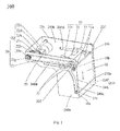
- a shutter mechanism 100 of the present application is mounted on a lateral frame 210 of a banknote port 230a of a financial automatic device and is electrically connected to a controller (not shown) of the device, and the banknote port 230a is provided on a front face 230 of the frame 210.
- the shutter mechanism 100 of the present application includes a shutter 10, a driving mechanism 20, and a locking mechanism 30 for controlling the shutter 10.
- the driving mechanism 20 and the locking mechanisms 30 are provided on the frame 210.
- a lower end of the shutter 10 is slidably connected to a front end 240a of a lateral surface 240 of the frame in an up-down direction (i.e. a direction indicated by an arrow on the shutter 10 in Fig.
- an upper end of the shutter 10 is slidably connected to an upper end 240b of the lateral surface 240 of the frame in a front-back direction (i.e. a direction indicated by an arrow on the lateral surface 240 of the frame in Fig. 1 ).
- the driving mechanism 20 drives the upper end of the shutter 10 to slide backward along the upper end 240b of the lateral surface 240 of the frame, and meanwhile drives the lower end of the shutter 10 to slide upward along the front end 240a of the lateral surface 240 of the frame, then the shutter 10 opens the banknote port 230a; the driving mechanism 20 drives the upper end of the shutter 10 to slide forward along the upper end 240b of the lateral surface 240 of the frame, and meanwhile drives the lower end of the shutter 10 to move downward along the front end 240a of the lateral surface 240 of the frame, then the shutter 10 closes the banknote port 230a, and then the locking mechanism 30 locks the shutter 10 closing the banknote port 230a.
- a first sliding groove 240c is provided at the front end 240a of the lateral surface 240 of the frame in an up-down direction
- a second sliding groove 240d is provided at the upper end 240b of the lateral surface 240 of the frame in a front-back direction
- a first sliding portion 10a extending from the lower end of the shutter 10 cooperates with the first sliding groove 240c
- a second sliding portion 10b extending from the upper end of the shutter 10 cooperates with the second sliding groove 240d.
- the sliding and turning motion of the shutter 10 is more reliable, when the lower end of the shutter 10 slides along the front end 240a of the lateral surface 240 of the frame up and down and the upper end of the shutter 10 slides along the upper end 240b of the lateral surface 240 of the frame front and back.
- the first sliding groove 240c includes a straight portion and an arc portion, the arc portion is curved in a direction away from the banknote port 230a and is provided adjacent to the second sliding groove 240d, and the second sliding groove 240d is a straight groove.
- two first sliding grooves 240c are provided symmetrically on two sides of the front end 240a of the lateral surface 240 of the frame respectively, and two second sliding grooves 240d are provided symmetrically on two sides of the upper end 240b of the lateral surface 240 of the frame respectively.
- two first sliding portions 10a are provided on two sides of the lower end of the shutter 10 respectively, and two second sliding portions 10b are provided on two sides of the upper end of the shutter 10 respectively.
- the first sliding portions 10a and the second sliding portions 10b are cylindrical, and the cylindrical first sliding portions 10a and second sliding portions 10b each are pivotally connected with a roller wheel 10c.
- the driving mechanism 20 includes a conveying member 21, a driving assembly 22, a locking assembly 23, and a second position sensor 24 electrically connected to the controller.
- the conveying member 21 is provided at the upper end 240b of the lateral surface 240 of the frame in a front-back direction, an output end of the driving assembly 22 is connected to the conveying member 21, and the second sliding portion 10b is fixed on the conveying member 21.
- the second sliding portion 10b is fixed on the conveying member 21 by the locking assembly 23, such that the driving assembly 22 may more easily drive the shutter 10 to open or close the banknote port 230 via the conveying member 21 and the second sliding portion 10b; and the locking assembly 23 fixedly connected to the second sliding portion 10b is fixed to the conveying member 21.
- Second position sensors 24 are respectively provided at the upper end 240b of the lateral surface 240 of the frame in a front-back direction and are located outside two sides of the locking assembly 23 respectively.
- a detecting sheet 23a of the locking assembly 23 is within a detecting region of the above second position sensor 24), and when the shutter 10 opens the banknote port 230a, the position of the locking assembly 23 corresponds to the other one of the second position sensors 24 (i.e. the detecting sheet 23a of the locking assembly 23 is within the detecting region of the above second position sensor 24), such that the controller may accurately control the shutter 10 to open or close the banknote port 230a via the driving mechanism 20.
- the driving assembly 22 includes a motor 22a, a driving gear 22b, a driven gear 22c, a driving shaft 22d, a primary driving wheel 22e, an auxiliary driving wheel 22f and a torque limiter 22h.
- the driving shaft 22d is pivotally connected to a rear of the upper end 240b of the lateral surface 240 of the frame and protrudes out of the upper end 240b of the lateral surface 240 of the frame to form a mounting end 22g.
- the primary driving wheel 22e is mounted on the mounting end 22g
- the auxiliary driving wheel 22f is pivotally connected to a front of the upper end 240b of the lateral surface 240 of the frame
- the conveying member 21 is surroundingly provided at outside of the primary driving wheel 22e and the auxiliary driving wheel 22f.
- the motor 22a is mounted on the upper end 240b of the lateral surface 240 of the frame via a mounting bracket 25 and is located between two lateral surfaces 240 of the frame, such that the structure of the frame 210 is more compact.
- the driving gear 22b is mounted on an output shaft of the motor 22a
- the driven gear 22c is mounted on the driving shaft 22d and is engaged with the driving gear 22b
- the torque limiter 22h is located between the driving shaft 22d and the driven gear 22c.
- two ends of the driving shaft 22d protrude out of the upper ends 240b of the two lateral surfaces 240 of the frame respectively to form two mounting ends 22g.
- Each mounting end 22g is mounted with a primary driving wheel 22e, correspondingly, there are two auxiliary driving wheels 22f corresponding to the two primary driving wheels 22e respectively; there are two conveying members 21, each of which is surroundingly provided at outside of one of the primary driving wheels 22e and one of the auxiliary driving wheels 22f; there are two locking assemblies 23, each of which is fixed on one of the conveying members 21 and is fixedly connected to one of the second sliding portions 10b of the shutter 10; and the number of the second position sensors 24 may remain unchanged, since the second position sensors 24 are only need to be mounted on either of the upper ends 240b of the two lateral surfaces 240 of the frame.
- An object of such design is to realize the both-side synchronous driving of the shutter 10 by the driving assembly 22.
- one end of the driving shaft 22d protrudes out of the upper end 240b of one lateral surface 240 of the frame to form one mounting end 22g
- one primary driving wheel 22e is mounted on the mounting end 22g
- one auxiliary driving wheel 22f is provided to correspond to the primary driving wheel 22e
- one conveying member 21 is surroundingly provided at outside of the primary driving wheel 22e and the auxiliary driving wheel 22f
- one locking assembly 23 is fixed on the conveying member 21 and is fixedly connected to one second sliding portion 10b of the shutter 10, due to the cooperating of the above components, an object of single-side driving of the shutter 10 by the driving assembly 22 can also be realized.
- the driving assembly 22 is composed of the motor 22a, the driving gear 22b, the driven gear 22c, the driving shaft 22d, the primary driving wheel 22e, the auxiliary driving wheel 22f and the torque limiter 22h
- the structure of the driving assembly 22 is simple and the dismounting and the maintenance are convenient, thereby further miniaturizing the shutter mechanism 100 of the present application.
- Due to the torque limiter 22h an excessive clamping force when the closing is overloaded is avoided, components being impacted repeatedly when the opening is overloaded is also prevented, thereby ensuring the shutter mechanism 100 of the present application working more reliably.
- the conveying member 21 may be a conveying belt or a conveying chain, such that the structure of the conveying member 21 is simple and practical.
- the locking mechanism 30 includes a locking and driving assembly (not shown) electrically connected to the controller, and a locking plate 31 located above the banknote port 230a and pivotally connected to the frame 210 via a rotating shaft 33.
- the locking and driving assembly drives the locking plate 31 to abut against and lock the shutter 10 when the shutter 10 closes the banknote port 230a, such that when closing the banknote port 230a, the shutter 10 is in a locked state, thereby preventing violent pry or damaging force action to some extent and ensuring the security of the banknote inside the financial self-service device and the security of the corresponding components of the shutter mechanism 100 of the present application.
- the locking mechanism 30 further includes a first position sensor 32 electrically connected to the controller and provided at the upper end 240b of the lateral surface 240 of the frame.
- One end of the locking plate 31 is extended toward the banknote port 230a to form a locking portion 31a
- the other end of the locking plate 31 is extended toward the first position sensor 32 to form a sensing portion 31b
- a position of the sensing portion 31b corresponds to the first position sensor 32 (i.e. the sensing portion 31b is within a detecting region of the first position sensor 32), when the shutter 10 closes the banknote port 230a and the locking portion 31 a abuts against and locks the shutter 10.
- the controller can accurately control the locking mechanism 30 to lock or loosen the shutter 10. Since the locking portion 31 a abuts and locks the shutter 10, the stress direction of the shutter 10 is reasonable, thereby further ensuring the security of the banknote inside the financial self-service device and the security of the corresponding structures of the shutter mechanism 100 of the present application.
- Two locking portions 31a are provided at two sides of the locking plate 31 respectively, such that the locking force at various positions of the shutter 10 is more even, thereby further increasing the locking force and meanwhile avoiding the deformation of the shutter caused by uneven stress.
- the process of the opening and closing actions of the shutter of the shutter mechanism of the present application is described as follows.
- the locking plate 31 of the locking mechanism 30 is in a reset state as shown in Fig. 2 , in this state the sensing portion 31b of the locking plate 31 blocks a detecting signal of the first position sensor 32, and the locking portion 31 a of the locking plate 31 abuts against the upper end of the shutter 10 to lock the shutter 10, such that the shutter 10 can not move, and the shutter 10, that can not move, closes the banknote port 230a.
- the controller When needs to open the banknote port 230a by the shutter 10, the controller sends a driving or controlling signal, the locking plate 31 is driven by the locking and driving assembly to rotate around the rotating shaft 33 (i.e. rotate in an anticlockwise direction in Fig. 2 ), such that the locking portion 31a of the locking plate 31 is lifted to avoid the enveloping space of the motion of the shutter 10.
- the sensing portion 31b of the locking plate 31 deviates from the detecting region of the first position sensor 32, and the controller receives an unblocked detecting signal from the first position sensor 32, which indicates that the opening action of the locking plate 31 of the locking mechanism 30 is completed; then the controller sends a driving or controlling signal to start the motor 22a, the driving gear 22b engages with the driven gear 22c to transmit power to the torque limiter 22h, the driving shaft 22d is driven by the torque limiter 22h to rotate, and the primary driving wheel 22e, the auxiliary driving wheel 22f and the conveying belt 21 cooperate to transmit the power to the locking assembly 23, then the locking assembly 23 transmits the power to the second sliding portions 10b at two sides of the shutter 10, such that the upper end of the shutter 10 is driven by the second sliding portions 10b to move along the second sliding groove 240d, and meanwhile the lower end of the shutter 10 moves along the first sliding groove 240c.
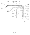
- the second sliding portion 10b of the shutter 10 slides leftward in Fig. 4 along the second sliding groove 240d, meanwhile the first sliding portion 10a of the shutter 10 slides upward in Fig. 4 along the first sliding groove 240c, such that the shutter 10 may make a rigid planar motion combining the sliding and rotating motions.
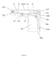
- one of the second position sensors 24, corresponding to a state that the shutter 10 is opened in place detects that the detecting sheet 23a of the locking assembly 23 is in place (as shown in Figs. 2 and 3 ), the shutter 10 is opened in place, corresponding to a state shown in Fig. 4a , and completes the action of opening the banknote port 230a.
- the controller sends a driving or controlling signal to the locking and driving assembly
- the locking and driving assembly drives the locking plate 31 to rotate around the rotating shaft 33 to return to the original position
- the sensing portion 31b blocks the detecting signal of the first position sensor 32
- the first position sensor 32 sends a detecting signal to the controller to be analyzed, such that the controller determines that the locking plate 31 is returned to the original position.
- the controller When needs to close the banknote port 230a by the shutter 10, the controller sends a driving or controlling signal to the locking and driving assembly, then the locking and driving assembly drives the locking plate 31 to rotate around the rotating shaft 33 (i.e. in the anticlockwise direction in Fig. 2 ), such that the locking portion 31a of the locking plate 31 is lifted to avoid the enveloping space of the motion of the shutter 10. And at the same time, the sensing portion 31b of the locking plate 31 deviates from the detecting region of the first position sensor 32, then the first position sensor 32 sends an unblocked detecting signal to the controller to be analyzed and processed, such that the controller determines that the opening action of the locking plate 31 is completed.
- the controller sends a driving or controlling signal to drive the motor 22a to rotate in a reverse direction
- the driving gear 22b engages with the driven gear 22c to transmit power to the torque limiter 22h
- the driving shaft 22d is driven by the torque limiter 22h to rotate
- the primary driving wheel 22e, the auxiliary driving wheel 22f and the conveying belt 21 cooperate to transmit the power to the locking assembly 23 so as to drive the shutter 10, such that the second sliding portion 10b of the shutter 10 slides rightward along the second sliding groove 240d as shown in Fig. 4 , meanwhile the first sliding portion 10a of the shutter 10 slides downward along the first sliding groove 240c as shown in Fig. 4 , such that the shutter 10 can make a rigid planar motion combining the sliding and rotating motions.
- the controller sends a driving or controlling signal
- the locking and driving assembly drives the locking plate 31 to rotate around the rotating shaft 33 to return to the original position, and when the locking plate 31 rotates back to a specific position, the sensing portion 31b blocks the detecting signal of the first position sensor 32, then the first position sensor 32 sends a blocked detecting signal to the controller to be analyzed, such that the controller determines that the locking plate 31 is returned to the original position, and at this time, the locking portion 31a of the locking plate 31 abuts against the upper end of the shutter 10 and locks the shutter 10.
- the first sliding portion 10a is sliding along the first sliding groove 240c, such that the shutter 10 forms the space region, formed by grid lines, indicated by an arrow A in Fig. 5 .
- the first sliding portion 10a and the second sliding portion 10b of the shutter 10 from sliding out because of the first sliding portion 10a shaking inside the first sliding groove 240c and the second sliding portion 10b shaking inside the second sliding groove 240d front and back (i.e. in a direction perpendicular to the plane of Fig.
- a position-limiting structure for avoiding the front-back shaking is provided on each of the first sliding portion 10a and the second sliding portion 10b, thereby ensuring that the front-back shaking will not occur when the shutter 10 slides along the first sliding groove 240c and the second sliding groove 240d.
- the second sliding portion 10b of the shutter 10 are fixedly connected to the conveying belt 21 via the locking assembly 23, which ensures that the position of the second sliding portions 10b of the shutter 10 relative to the locking assembly 23 is fixed in a left-right direction in Fig. 4a and the shutter 10 may rotate around the second sliding portion 10b relative to the locking assembly 23 in an up-down direction in Fig. 4a .
- the lower end of the shutter 10 of the present application is slidably connected to the front end 240a of the lateral surface 240 of the frame in an up-down direction
- the upper end of the shutter 10 is slidably connected to the upper end 240b of the lateral surface 240 of the frame in a front-back direction
- the upper end of the shutter 10 is driven by the driving mechanism 20 to slide along the upper end 240b of the lateral surface 240 of the frame front and back
- the lower end of the shutter 10 is driven to move along the front end 240a of the lateral surface 240 of the frame up and down, such that the shutter 10 is driven by the driving mechanism 20 to make rigid planar motion (i.e.
- the shutter mechanism 100 of the present application can reduce the enveloping space generated by the motion of the shutter 10 and also reduce the space of the frame 210 occupied by the shutter 10, such that the structure of the shutter mechanism 100 of the present application is more compact.
Landscapes
- Physics & Mathematics (AREA)
- General Physics & Mathematics (AREA)
- Business, Economics & Management (AREA)
- Accounting & Taxation (AREA)
- Finance (AREA)
- Pile Receivers (AREA)
- Control Of Vending Devices And Auxiliary Devices For Vending Devices (AREA)
- Separation, Sorting, Adjustment, Or Bending Of Sheets To Be Conveyed (AREA)
- Sheets, Magazines, And Separation Thereof (AREA)
Abstract
Description
- The present application claims the priority of Chinese Patent Application No.
201110235749.0 - The present application relates to a shutter mechanism of a financial self-service device, and in particular to a shutter mechanism having a compact structure.
- The financial self-service device has been widely used in everyday life, and can provide 24-hour continuous service and bring significant convenience for customers. However, for the unattended automated teller machine, there exists a risk that the money of the depositor may be stolen or intercepted by criminals. Therefore, the application security of the financial self-service device is causing more and more attention. For providing a violence-preventing protection for the financial self-service device, there are several structural embodiments which can realize the function of a shutter of the financial self-service device, such as opening, closing and locking function.
- The shutter structure of some commercially available financial self-service devices mainly has two action principles, that is, a sliding manner, in which the shutter is placed horizontally or tilted at a certain degree, and a pivoting manner. One solution uses a principle of the shutter mechanism sliding back and forth in a certain plane. For example, as disclosed in a patent application No.
200910041871.7 CN101684713A , two planar sliding grooves are respectively provided at two sides of the shutter of the safe shutter device, the shutter mechanism is driven by a force to slide back and forth along a fixed sliding groove, and two extreme positions of the planar sliding groove respectively correspond to an open state and a close state of the shutter mechanism. The major problem of such shutter mechanism is that, because the mounting space is relatively large due to the alternative open and close states, the shutter mechanism is generally adapted to be placed horizontally or tilted. - In another solution, the shutter mechanism rotates around an axis to realize the open and close actions. For example, in the automatic shutter device disclosed in the patent application No.
200910193709.7 CN101840596A , one end of the shutter of the device is fixed on a rotating axis, and the shutter is driven by a force to rotate around the axis by a certain angle from an initial angle, such that the shutter is in close and open states respectively. The major problem of such shutter mechanism is that, the enveloping space of the spatial motion is relatively large due to the motion manner, thus enough space is required for realizing the action of the shutter, and if there is a requirement on the space limitation, the application of such shutter mechanism is not convenient. A shutter mechanism on the product LOBBY90 of Wincor Company, which also rotates around an axis, solves the problem of the large motion enveloping space, however the arc shutter plate causes a lot of inconveniences during the overall mounting and fitting process. - Further, for some through-the-all or outdoor placed financial self-service devices, the transaction interface is generally exposed, which requires the shutter having a certain rainproof function.
- Therefore, it is urgent to provide a shutter mechanism which is able to reduce the enveloping space of the motion of the shutter and has a compact structure.
- The object of the present application is to provide a shutter mechanism which is able to reduce the enveloping space of the motion of the shutter and has a compact structure.
- For realizing the above object, the present application provides a shutter mechanism mounted on a lateral frame of a banknote port of a financial self-service device. The shutter mechanism includes a shutter, a driving mechanism, and a locking mechanism for controlling the shutter. A lower end of the shutter is slidably connected to a front end of a lateral surface of the frame in an up-down direction, an upper end of the shutter is slidably connected to an upper end of the lateral surface of the frame in a front-back direction, and the upper end of the shutter is driven by the driving mechanism to slide along the upper end of the lateral surface of the frame front and back, which meanwhile drives the lower end of the shutter to move along the front end of the lateral surface of the frame up and down, thereby realizing the opening and closing of the shutter.
- Preferably, a first sliding groove is provided at the front end of the lateral surface of the frame in an up-down direction, a second sliding groove is provided at the upper end of the lateral surface of the frame in a front-back direction, a first sliding portion extending from the lower end of the shutter cooperates with the first sliding groove, and a second sliding portion extending from the upper end of the shutter cooperates with the second sliding groove. Due to the cooperating between the first sliding groove and the first sliding portion and the cooperating between the second sliding groove and the second sliding portion, the sliding and turning motion of the shutter is more reliable, when the lower end of the shutter slides along the front end of the lateral surface of the frame up and down and the upper end of the shutter slides along the upper end of the lateral surface of the frame front and back.
- Specifically, the first sliding groove includes a straight portion and an arc portion, the arc portion is curved in a direction away from the banknote port and is provided adjacent to the second sliding groove, and the second sliding groove is a straight groove, such that the enveloping space generated by the shutter when opening or closing the banknote port is smaller, thereby further creating a better condition for simplifying the structure of the shutter mechanism of the present application.
- Two first sliding portions are provided at two sides of the lower end of the shutter respectively, two second sliding portions are provided at two sides of the upper end of the shutter respectively, the first sliding portions and the second sliding portions are cylindrical, and the cylindrical first sliding portions and second sliding portions each are pivotally connected with a roller wheel. Due to the two first sliding portions provided at two sides and the two second sliding portions provided at two sides, the stress at various positions of the shutter is more even, thereby improving the accuracy and the reliability of the shutter when opening or closing the banknote port. Due to the roller wheel, the sliding of the shutter is more flexible and has smaller resisting force, such that the driving mechanism may more easily drive the shutter to open or close the banknote port.
- Preferably, the driving mechanism includes a conveying member and a driving assembly, the conveying member is provided at the upper end of the lateral surface of the frame in a front-back direction, an output end of the driving assembly is connected to the conveying member, and the second sliding portion is fixed on the conveying member, such that via the conveying member and the second sliding portion, the driving assembly may more easily drive the shutter to open or close the banknote port. Specifically, the driving mechanism further includes a second position sensor electrically connected to a controller of the financial self-service device, and a locking assembly. The second sliding portion is fixed on one end of the locking assembly, and the other end of the locking assembly is fixed on the conveying member. Two second position sensors are respectively provided at the upper end of the lateral surface of the frame in a front-back direction and are located outside two sides of the locking assembly respectively. A position of the locking assembly corresponds to one of the second position sensors when the shutter closes the banknote port, and the position of the locking assembly corresponds to the other one of the second position sensors when the shutter opens the banknote port, such that via the driving mechanism, the controller can accurately control the shutter to open or close the banknote port.
- More specifically, the driving assembly includes a motor, a driving gear, a driven gear, a driving shaft, a primary driving wheel and an auxiliary driving wheel. The driving shaft is pivotally connected to a rear of the upper end of the lateral surface of the frame, and protrudes out of the upper end of the lateral surface of the frame to form a mounting end. The primary driving wheel is mounted on the mounting end, and the auxiliary driving wheel is pivotally connected to a front of the upper end of the lateral surface of the frame at a position corresponding to the primary driving wheel. The conveying member is surroundingly provided at outside of the primary driving wheel and the auxiliary driving wheel, the motor is mounted on the frame, the driving gear is mounted on an output shaft of the motor, the driven gear is mounted on the driving shaft and is engaged with the driving gear, and a torque limiter is provided between the driving shaft and the driven gear. The above configuration may simplify the structure of the driving assembly, facilitate the dismounting and the maintenance, and further miniaturize the shutter mechanism of the present application on one hand; and avoid an excessive clamping force when the closing is overloaded, and prevent components from being impacted repeatedly when the opening is overloaded on the other hand, thereby ensuring the shutter mechanism of the present application working more reliably.
- Preferably, the locking mechanism includes a locking and driving assembly electrically connected to the controller, and a locking plate located above the banknote port and pivotally connected to the frame. The locking and driving assembly drives the locking plate to abut against and lock the shutter when the shutter closes the banknote port, such that when closing the banknote port, the shutter is in a locked state, thereby preventing violent pry or damaging force action to some extent and ensuring the security of the banknote inside the financial self-service device and the security of corresponding components of the shutter mechanism of the present application. Specifically, the locking mechanism further includes a first position sensor electrically connected to the controller and provided at the upper end of the lateral surface of the frame. One end of the locking plate is extended toward the banknote port to form a locking portion, and the other end of the locking plate is extended toward the first position sensor to form a sensing portion. A position of the sensing portion corresponds to the first position sensor, when the shutter closes the banknote port and the locking portion abuts against and locks the shutter. Due to the first position sensor, the controller can accurately control the locking mechanism to lock or loosen the shutter. Since the locking portion abuts and locks the shutter, a stress direction of the shutter is reasonable, thereby further ensuring the security of the banknote inside the financial self-service device and the security of corresponding structures of the shutter mechanism of the present application. More specifically, two locking portions are provided at two sides of the locking plate respectively, such that the locking force at various positions of the shutter is more even, thereby further increasing the locking force and meanwhile avoiding the deformation of the shutter caused by uneven stress.
- Compared to the prior art, the lower end of the shutter of the present application is slidably connected to the front end of the lateral surface of the frame in an up-down direction, the upper end of the shutter is slidably connected to the upper end of the lateral surface of the frame in a front-back direction, and the upper end of the shutter is driven by the driving mechanism to slide along the upper end of the lateral surface of the frame front and back, and meanwhile the lower end of the shutter is driven to slide along the front end of the lateral surface of the frame up and down, such that the shutter is driven by the driving mechanism to make rigid planar motion (i.e. combining the existing sliding manner, sliding back and forth in a certain plane, and pivoting manner of the shutter), which overcomes the disadvantage of the existing sliding shutter mechanism or the pivoting shutter mechanism that the space occupied by the shutter mechanism is relatively large due to the extremely huge enveloping space generated by the motion of the shutter. Therefore, the shutter mechanism of the present application can reduce the enveloping space generated by the motion of the shutter and can also reduce the space of the frame occupied by the shutter, such that the structure of the shutter mechanism of the present application is more compact.
-
-
Figure 1 is a perspective view of a shutter mechanism of the present application; -
Figure 2 is a structural schematic view of the shutter mechanism shown inFig. 1 , in which a lateral surface of a frame is removed; -
Figure 3 is a structural schematic view ofFig. 2 viewed from another angle; -
Figures 4a and4b are schematic views of working states of the shutter mechanism of the present application; and -
Figure 5 is a structural schematic view of an enveloping space generated by the motion of a shutter of the shutter mechanism of the present application on a lateral surface of the frame. - For illustrating technical contents and structural features of the present application in detail, the present application is further described below in conjunction with embodiments and drawings.
- Referring to
Fig. 1 , ashutter mechanism 100 of the present application is mounted on alateral frame 210 of abanknote port 230a of a financial automatic device and is electrically connected to a controller (not shown) of the device, and thebanknote port 230a is provided on afront face 230 of theframe 210. Theshutter mechanism 100 of the present application includes ashutter 10, adriving mechanism 20, and alocking mechanism 30 for controlling theshutter 10. Thedriving mechanism 20 and thelocking mechanisms 30 are provided on theframe 210. Meanwhile, a lower end of theshutter 10 is slidably connected to afront end 240a of alateral surface 240 of the frame in an up-down direction (i.e. a direction indicated by an arrow on theshutter 10 inFig. 1 ), and an upper end of theshutter 10 is slidably connected to anupper end 240b of thelateral surface 240 of the frame in a front-back direction (i.e. a direction indicated by an arrow on thelateral surface 240 of the frame inFig. 1 ). Thedriving mechanism 20 drives the upper end of theshutter 10 to slide backward along theupper end 240b of thelateral surface 240 of the frame, and meanwhile drives the lower end of theshutter 10 to slide upward along thefront end 240a of thelateral surface 240 of the frame, then theshutter 10 opens thebanknote port 230a; thedriving mechanism 20 drives the upper end of theshutter 10 to slide forward along theupper end 240b of thelateral surface 240 of the frame, and meanwhile drives the lower end of theshutter 10 to move downward along thefront end 240a of thelateral surface 240 of the frame, then theshutter 10 closes thebanknote port 230a, and then thelocking mechanism 30 locks theshutter 10 closing thebanknote port 230a. - Specifically, referring to
Figs. 1 ,3 ,4a and4b , a first slidinggroove 240c is provided at thefront end 240a of thelateral surface 240 of the frame in an up-down direction, a secondsliding groove 240d is provided at theupper end 240b of thelateral surface 240 of the frame in a front-back direction, a first slidingportion 10a extending from the lower end of theshutter 10 cooperates with the first slidinggroove 240c, and a second slidingportion 10b extending from the upper end of theshutter 10 cooperates with the second slidinggroove 240d. Due to the cooperating between the first slidinggroove 240c and the first slidingportion 10a and the cooperating between the second slidinggroove 240d and the second slidingportion 10b, the sliding and turning motion of theshutter 10 is more reliable, when the lower end of theshutter 10 slides along thefront end 240a of thelateral surface 240 of the frame up and down and the upper end of theshutter 10 slides along theupper end 240b of thelateral surface 240 of the frame front and back. For further reducing the enveloping space generated by theshutter 10 when opening or closing thebanknote port 230a so as to further create a better condition for simplifying the structure of theshutter mechanism 100 of the application, the first slidinggroove 240c includes a straight portion and an arc portion, the arc portion is curved in a direction away from thebanknote port 230a and is provided adjacent to the second slidinggroove 240d, and the second slidinggroove 240d is a straight groove. For further miniaturizing theshutter mechanism 100 of the present application and facilitating the motion of theshutter 10, in this embodiment, two first slidinggrooves 240c are provided symmetrically on two sides of thefront end 240a of thelateral surface 240 of the frame respectively, and two second slidinggrooves 240d are provided symmetrically on two sides of theupper end 240b of thelateral surface 240 of the frame respectively. In order that the stress at various positions of theshutter 10 is more even so as to improve the accuracy and the reliability of theshutter 10 when opening or closing thebanknote port 230a, two first slidingportions 10a are provided on two sides of the lower end of theshutter 10 respectively, and two second slidingportions 10b are provided on two sides of the upper end of theshutter 10 respectively. In order that the sliding of theshutter 10 is more flexible and has smaller resisting force so as to make it easier for thedriving mechanism 20 to drive theshutter 10 to open or close thebanknote port 230a, the first slidingportions 10a and the second slidingportions 10b are cylindrical, and the cylindrical first slidingportions 10a and second slidingportions 10b each are pivotally connected with aroller wheel 10c. - Referring to
Figs. 1 to 4b , thedriving mechanism 20 includes a conveyingmember 21, a drivingassembly 22, a lockingassembly 23, and asecond position sensor 24 electrically connected to the controller. The conveyingmember 21 is provided at theupper end 240b of thelateral surface 240 of the frame in a front-back direction, an output end of the drivingassembly 22 is connected to the conveyingmember 21, and the second slidingportion 10b is fixed on the conveyingmember 21. In this embodiment, the second slidingportion 10b is fixed on the conveyingmember 21 by the lockingassembly 23, such that the drivingassembly 22 may more easily drive theshutter 10 to open or close thebanknote port 230 via the conveyingmember 21 and the second slidingportion 10b; and the lockingassembly 23 fixedly connected to the second slidingportion 10b is fixed to the conveyingmember 21.Second position sensors 24 are respectively provided at theupper end 240b of thelateral surface 240 of the frame in a front-back direction and are located outside two sides of the lockingassembly 23 respectively. When theshutter 10 closes thebanknote port 230a, a position of the lockingassembly 23 corresponds to one of the second position sensors 24 (i.e. a detectingsheet 23a of the lockingassembly 23 is within a detecting region of the above second position sensor 24), and when theshutter 10 opens thebanknote port 230a, the position of the lockingassembly 23 corresponds to the other one of the second position sensors 24 (i.e. the detectingsheet 23a of the lockingassembly 23 is within the detecting region of the above second position sensor 24), such that the controller may accurately control theshutter 10 to open or close thebanknote port 230a via thedriving mechanism 20. - More specifically, the driving
assembly 22 includes amotor 22a, adriving gear 22b, a drivengear 22c, a drivingshaft 22d, aprimary driving wheel 22e, anauxiliary driving wheel 22f and atorque limiter 22h. The drivingshaft 22d is pivotally connected to a rear of theupper end 240b of thelateral surface 240 of the frame and protrudes out of theupper end 240b of thelateral surface 240 of the frame to form a mountingend 22g. Theprimary driving wheel 22e is mounted on the mountingend 22g, theauxiliary driving wheel 22f is pivotally connected to a front of theupper end 240b of thelateral surface 240 of the frame, and the conveyingmember 21 is surroundingly provided at outside of theprimary driving wheel 22e and theauxiliary driving wheel 22f. Themotor 22a is mounted on theupper end 240b of thelateral surface 240 of the frame via a mountingbracket 25 and is located between twolateral surfaces 240 of the frame, such that the structure of theframe 210 is more compact. Thedriving gear 22b is mounted on an output shaft of themotor 22a, the drivengear 22c is mounted on the drivingshaft 22d and is engaged with thedriving gear 22b, and thetorque limiter 22h is located between the drivingshaft 22d and the drivengear 22c. - In this embodiment, two ends of the driving
shaft 22d protrude out of the upper ends 240b of the twolateral surfaces 240 of the frame respectively to form two mountingends 22g. Each mountingend 22g is mounted with aprimary driving wheel 22e, correspondingly, there are twoauxiliary driving wheels 22f corresponding to the twoprimary driving wheels 22e respectively; there are two conveyingmembers 21, each of which is surroundingly provided at outside of one of theprimary driving wheels 22e and one of theauxiliary driving wheels 22f; there are two lockingassemblies 23, each of which is fixed on one of the conveyingmembers 21 and is fixedly connected to one of the second slidingportions 10b of theshutter 10; and the number of thesecond position sensors 24 may remain unchanged, since thesecond position sensors 24 are only need to be mounted on either of the upper ends 240b of the twolateral surfaces 240 of the frame. An object of such design is to realize the both-side synchronous driving of theshutter 10 by the drivingassembly 22. Certainly, one end of the drivingshaft 22d protrudes out of theupper end 240b of onelateral surface 240 of the frame to form one mountingend 22g, oneprimary driving wheel 22e is mounted on the mountingend 22g, oneauxiliary driving wheel 22f is provided to correspond to theprimary driving wheel 22e, one conveyingmember 21 is surroundingly provided at outside of theprimary driving wheel 22e and theauxiliary driving wheel 22f, one lockingassembly 23 is fixed on the conveyingmember 21 and is fixedly connected to one second slidingportion 10b of theshutter 10, due to the cooperating of the above components, an object of single-side driving of theshutter 10 by the drivingassembly 22 can also be realized. Due to fact that the drivingassembly 22 is composed of themotor 22a, thedriving gear 22b, the drivengear 22c, the drivingshaft 22d, theprimary driving wheel 22e, theauxiliary driving wheel 22f and thetorque limiter 22h, the structure of the drivingassembly 22 is simple and the dismounting and the maintenance are convenient, thereby further miniaturizing theshutter mechanism 100 of the present application. Due to thetorque limiter 22h, an excessive clamping force when the closing is overloaded is avoided, components being impacted repeatedly when the opening is overloaded is also prevented, thereby ensuring theshutter mechanism 100 of the present application working more reliably. The conveyingmember 21 may be a conveying belt or a conveying chain, such that the structure of the conveyingmember 21 is simple and practical. - Referring to
Figs. 1 to 4b again, thelocking mechanism 30 includes a locking and driving assembly (not shown) electrically connected to the controller, and a lockingplate 31 located above thebanknote port 230a and pivotally connected to theframe 210 via a rotatingshaft 33. The locking and driving assembly drives the lockingplate 31 to abut against and lock theshutter 10 when theshutter 10 closes thebanknote port 230a, such that when closing thebanknote port 230a, theshutter 10 is in a locked state, thereby preventing violent pry or damaging force action to some extent and ensuring the security of the banknote inside the financial self-service device and the security of the corresponding components of theshutter mechanism 100 of the present application. In this embodiment, thelocking mechanism 30 further includes afirst position sensor 32 electrically connected to the controller and provided at theupper end 240b of thelateral surface 240 of the frame. One end of the lockingplate 31 is extended toward thebanknote port 230a to form a lockingportion 31a, the other end of the lockingplate 31 is extended toward thefirst position sensor 32 to form asensing portion 31b, and a position of thesensing portion 31b corresponds to the first position sensor 32 (i.e. thesensing portion 31b is within a detecting region of the first position sensor 32), when theshutter 10 closes thebanknote port 230a and the lockingportion 31 a abuts against and locks theshutter 10. Due to thefirst position sensor 32, the controller can accurately control thelocking mechanism 30 to lock or loosen theshutter 10. Since the lockingportion 31 a abuts and locks theshutter 10, the stress direction of theshutter 10 is reasonable, thereby further ensuring the security of the banknote inside the financial self-service device and the security of the corresponding structures of theshutter mechanism 100 of the present application. Two lockingportions 31a are provided at two sides of the lockingplate 31 respectively, such that the locking force at various positions of theshutter 10 is more even, thereby further increasing the locking force and meanwhile avoiding the deformation of the shutter caused by uneven stress. - In conjunction with the drawings, the process of the opening and closing actions of the shutter of the shutter mechanism of the present application is described as follows. In a normal state, under the action of the locking and driving assembly, the locking
plate 31 of thelocking mechanism 30 is in a reset state as shown inFig. 2 , in this state the sensingportion 31b of the lockingplate 31 blocks a detecting signal of thefirst position sensor 32, and the lockingportion 31 a of the lockingplate 31 abuts against the upper end of theshutter 10 to lock theshutter 10, such that theshutter 10 can not move, and theshutter 10, that can not move, closes thebanknote port 230a. When needs to open thebanknote port 230a by theshutter 10, the controller sends a driving or controlling signal, the lockingplate 31 is driven by the locking and driving assembly to rotate around the rotating shaft 33 (i.e. rotate in an anticlockwise direction inFig. 2 ), such that the lockingportion 31a of the lockingplate 31 is lifted to avoid the enveloping space of the motion of theshutter 10. At this time thesensing portion 31b of the lockingplate 31 deviates from the detecting region of thefirst position sensor 32, and the controller receives an unblocked detecting signal from thefirst position sensor 32, which indicates that the opening action of the lockingplate 31 of thelocking mechanism 30 is completed; then the controller sends a driving or controlling signal to start themotor 22a, thedriving gear 22b engages with the drivengear 22c to transmit power to thetorque limiter 22h, the drivingshaft 22d is driven by thetorque limiter 22h to rotate, and theprimary driving wheel 22e, theauxiliary driving wheel 22f and the conveyingbelt 21 cooperate to transmit the power to the lockingassembly 23, then the lockingassembly 23 transmits the power to the second slidingportions 10b at two sides of theshutter 10, such that the upper end of theshutter 10 is driven by the second slidingportions 10b to move along the second slidinggroove 240d, and meanwhile the lower end of theshutter 10 moves along the first slidinggroove 240c. Due to the limitation of the first slidinggroove 240c and the second slidinggroove 240d, the second slidingportion 10b of theshutter 10 slides leftward inFig. 4 along the second slidinggroove 240d, meanwhile the first slidingportion 10a of theshutter 10 slides upward inFig. 4 along the first slidinggroove 240c, such that theshutter 10 may make a rigid planar motion combining the sliding and rotating motions. When one of thesecond position sensors 24, corresponding to a state that theshutter 10 is opened in place, detects that the detectingsheet 23a of the lockingassembly 23 is in place (as shown inFigs. 2 and3 ), theshutter 10 is opened in place, corresponding to a state shown inFig. 4a , and completes the action of opening thebanknote port 230a. At this time, the controller sends a driving or controlling signal to the locking and driving assembly, the locking and driving assembly drives the lockingplate 31 to rotate around the rotatingshaft 33 to return to the original position, and when the lockingplate 31 rotates back to a specific position, thesensing portion 31b blocks the detecting signal of thefirst position sensor 32, then thefirst position sensor 32 sends a detecting signal to the controller to be analyzed, such that the controller determines that the lockingplate 31 is returned to the original position. - When needs to close the
banknote port 230a by theshutter 10, the controller sends a driving or controlling signal to the locking and driving assembly, then the locking and driving assembly drives the lockingplate 31 to rotate around the rotating shaft 33 (i.e. in the anticlockwise direction inFig. 2 ), such that the lockingportion 31a of the lockingplate 31 is lifted to avoid the enveloping space of the motion of theshutter 10. And at the same time, thesensing portion 31b of the lockingplate 31 deviates from the detecting region of thefirst position sensor 32, then thefirst position sensor 32 sends an unblocked detecting signal to the controller to be analyzed and processed, such that the controller determines that the opening action of the lockingplate 31 is completed. Then the controller sends a driving or controlling signal to drive themotor 22a to rotate in a reverse direction, thedriving gear 22b engages with the drivengear 22c to transmit power to thetorque limiter 22h, the drivingshaft 22d is driven by thetorque limiter 22h to rotate, then theprimary driving wheel 22e, theauxiliary driving wheel 22f and the conveyingbelt 21 cooperate to transmit the power to the lockingassembly 23 so as to drive theshutter 10, such that the second slidingportion 10b of theshutter 10 slides rightward along the second slidinggroove 240d as shown inFig. 4 , meanwhile the first slidingportion 10a of theshutter 10 slides downward along the first slidinggroove 240c as shown inFig. 4 , such that theshutter 10 can make a rigid planar motion combining the sliding and rotating motions. When one of thesecond position sensors 24, corresponding to a state that theshutter 10 is closed in place, detects that the detectingsheet 23a of the lockingassembly 23 is in place, theshutter 10 is closed in place, corresponding to a state shown inFig. 4b , and completes the action of closing thebanknote port 230a. At this time, the controller sends a driving or controlling signal, the locking and driving assembly drives the lockingplate 31 to rotate around the rotatingshaft 33 to return to the original position, and when the lockingplate 31 rotates back to a specific position, thesensing portion 31b blocks the detecting signal of thefirst position sensor 32, then thefirst position sensor 32 sends a blocked detecting signal to the controller to be analyzed, such that the controller determines that the lockingplate 31 is returned to the original position, and at this time, the lockingportion 31a of the lockingplate 31 abuts against the upper end of theshutter 10 and locks theshutter 10. Wherein, when the second slidingportion 10b of theshutter 10 is sliding along the second slidinggroove 240d, the first slidingportion 10a is sliding along the first slidinggroove 240c, such that theshutter 10 forms the space region, formed by grid lines, indicated by an arrow A inFig. 5 . For preventing the first slidingportion 10a and the second slidingportion 10b of theshutter 10 from sliding out because of the first slidingportion 10a shaking inside the first slidinggroove 240c and the second slidingportion 10b shaking inside the second slidinggroove 240d front and back (i.e. in a direction perpendicular to the plane ofFig. 4a ), a position-limiting structure (not shown) for avoiding the front-back shaking is provided on each of the first slidingportion 10a and the second slidingportion 10b, thereby ensuring that the front-back shaking will not occur when theshutter 10 slides along the first slidinggroove 240c and the second slidinggroove 240d. The second slidingportion 10b of theshutter 10 are fixedly connected to the conveyingbelt 21 via the lockingassembly 23, which ensures that the position of the second slidingportions 10b of theshutter 10 relative to the lockingassembly 23 is fixed in a left-right direction inFig. 4a and theshutter 10 may rotate around the second slidingportion 10b relative to the lockingassembly 23 in an up-down direction inFig. 4a . - The lower end of the
shutter 10 of the present application is slidably connected to thefront end 240a of thelateral surface 240 of the frame in an up-down direction, the upper end of theshutter 10 is slidably connected to theupper end 240b of thelateral surface 240 of the frame in a front-back direction, and the upper end of theshutter 10 is driven by thedriving mechanism 20 to slide along theupper end 240b of thelateral surface 240 of the frame front and back, and meanwhile the lower end of theshutter 10 is driven to move along thefront end 240a of thelateral surface 240 of the frame up and down, such that theshutter 10 is driven by thedriving mechanism 20 to make rigid planar motion (i.e. combining the existing sliding manner, sliding back and forth in a certain plane, and pivoting manner of the shutter), which overcomes the disadvantage of the existing sliding shutter mechanism or the pivoting shutter mechanism that the space occupied by the shutter mechanism is relatively large due to the extremely huge enveloping space generated by the motion of the shutter. Therefore, theshutter mechanism 100 of the present application can reduce the enveloping space generated by the motion of theshutter 10 and also reduce the space of theframe 210 occupied by theshutter 10, such that the structure of theshutter mechanism 100 of the present application is more compact. - The above disclosures are only several embodiments of the present application, and the protection scope of the present application is not limited to above embodiments; therefore, equivalent variations made based on the claims of the present application are also deemed to fall into the protection scope of the present application.
Claims (10)
- A shutter mechanism, being mounted on a lateral frame of a banknote port of a financial self-service device, comprising a shutter, a driving mechanism, and a locking mechanism for controlling the shutter, wherein a lower end of the shutter is slidably connected to a front end of a lateral surface of the frame in an up-down direction, an upper end of the shutter is slidably connected to an upper end of the lateral surface of the frame in a front-back direction, the upper end of the shutter is driven by the driving mechanism to slide along the upper end of the lateral surface of the frame front and back, which meanwhile drives the lower end of the shutter to move along the front end of the lateral surface of the frame up and down, thereby realizing the opening and closing of the shutter.
- The shutter mechanism according to claim 1, wherein a first sliding groove is provided at the front end of the lateral surface of the frame in an up-down direction, a second sliding groove is provided at the upper end of the lateral surface of the frame in a front-back direction, a first sliding portion extending from the lower end of the shutter cooperates with the first sliding groove, and a second sliding portion extending from the upper end of the shutter cooperates with the second sliding groove.
- The shutter mechanism according to claim 2, wherein the first sliding groove comprises a straight portion and an arc portion, the arc portion is curved in a direction away from the banknote port and is provided adjacent to the second sliding groove, and the second sliding groove is a straight groove.
- The shutter mechanism according to claim 2, wherein two first sliding portions are provided at two sides of the lower end of the shutter respectively, two second sliding portions are provided at two sides the upper end of the shutter respectively, the first sliding portions and the second sliding portions are cylindrical, and the cylindrical first sliding portions and second sliding portions each are pivotally connected with a roller wheel.
- The shutter mechanism according to any one of claims 2 to 4, wherein the driving mechanism comprises a conveying member and a driving assembly, the conveying member is provided at the upper end of the lateral surface of the frame in a front-back direction, an output end of the driving assembly is connected to the conveying member, and the second sliding portion is fixed on the conveying member.
- The shutter mechanism according to claim 5, wherein the driving mechanism further comprises a second position sensor electrically connected to a controller of the financial self-service device, and a locking assembly; the second sliding portion is fixed on one end of the locking assembly, the other end of the locking assembly is fixed on the conveying member, two second position sensors are respectively provided at the upper end of the lateral surface of the frame in a front-back direction and are located outside two sides of the locking assembly respectively; a position of the locking assembly corresponds to one of the second position sensors when the shutter closes the banknote port, and the position of the locking assembly corresponds to the other one of the second position sensors when the shutter opens the banknote port.
- The shutter mechanism according to claim 6, wherein the driving assembly comprises a motor, a driving gear, a driven gear, a driving shaft, a primary driving wheel and an auxiliary driving wheel; the driving shaft is pivotally connected to a rear of the upper end of the lateral surface of the frame and protrudes out of the upper end of the lateral surface of the frame to form a mounting end, the primary driving wheel is mounted on the mounting end, the auxiliary driving wheel is pivotally connected to a front of the upper end of the lateral surface of the frame at a position corresponding to the primary driving wheel, the conveying member is surroundingly provided at outside of the primary driving wheel and the auxiliary driving wheel, the motor is mounted on the frame, the driving gear is mounted on an output shaft of the motor, the driven gear is mounted on the driving shaft and is engaged with the driving gear, and a torque limiter is provided between the driving shaft and the driven gear.
- The shutter mechanism according to claim 1, wherein the locking mechanism comprises a locking and driving assembly electrically connected to a controller of the financial self-service device, and a locking plate located above the banknote port and pivotally connected to the frame; and the locking and driving assembly drives the locking plate to abut and lock the shutter when the shutter closes the banknote port.
- The mechanism according to claim 8, wherein the locking mechanism further comprises a first position sensor electrically connected to the controller and provided at the upper end of the lateral surface of the frame; one end of the locking plate is extended toward the banknote port to form a locking portion, the other end of the locking plate is extended toward the first position sensor to form a sensing portion, and a position of the sensing portion corresponds to the first position sensor, when the shutter closes the banknote port and the locking portion abuts against and locks the shutter.
- The shutter mechanism according to claim 9, wherein two locking portions are provided at two sides of the locking plate respectively.
Applications Claiming Priority (2)
| Application Number | Priority Date | Filing Date | Title |
|---|---|---|---|
| CN2011102357490A CN102289862B (en) | 2011-08-17 | 2011-08-17 | Gate mechanism |
| PCT/CN2012/078351 WO2013023503A1 (en) | 2011-08-17 | 2012-07-09 | Gate mechanism |
Publications (3)
| Publication Number | Publication Date |
|---|---|
| EP2747044A1 true EP2747044A1 (en) | 2014-06-25 |
| EP2747044A4 EP2747044A4 (en) | 2015-02-25 |
| EP2747044B1 EP2747044B1 (en) | 2016-09-14 |
Family
ID=45336246
Family Applications (1)
| Application Number | Title | Priority Date | Filing Date |
|---|---|---|---|
| EP12823342.6A Not-in-force EP2747044B1 (en) | 2011-08-17 | 2012-07-09 | Gate mechanism |
Country Status (7)
| Country | Link |
|---|---|
| US (1) | US8919525B2 (en) |
| EP (1) | EP2747044B1 (en) |
| CN (1) | CN102289862B (en) |
| AU (1) | AU2012297408B2 (en) |
| CL (1) | CL2013002388A1 (en) |
| WO (1) | WO2013023503A1 (en) |
| ZA (1) | ZA201306051B (en) |
Cited By (2)
| Publication number | Priority date | Publication date | Assignee | Title |
|---|---|---|---|---|
| WO2016107850A1 (en) | 2014-12-29 | 2016-07-07 | Universite De Bretagne Occidentale | Method for obtaining a superoxide dismutase (sod)-concentrated protein extract |
| CN106780968A (en) * | 2015-11-23 | 2017-05-31 | 聚龙股份有限公司 | A kind of finance device gate mechanism |
Families Citing this family (38)
| Publication number | Priority date | Publication date | Assignee | Title |
|---|---|---|---|---|
| CN102289862B (en) * | 2011-08-17 | 2013-06-26 | 广州广电运通金融电子股份有限公司 | Gate mechanism |
| CN102722936B (en) * | 2012-06-21 | 2013-12-18 | 广州御银科技股份有限公司 | Mechanical cash-out shutter of ATM (Automatic Teller Machine) |
| CN103352967B (en) * | 2013-06-20 | 2016-01-20 | 广州广电运通金融电子股份有限公司 | A kind of paper money storage box |
| CN104167044B (en) * | 2013-09-12 | 2017-01-04 | 深圳市创自技术有限公司 | Paper money identification equipment and self-aided terminal |
| CN104778762B (en) * | 2014-01-13 | 2017-12-22 | 北京兆维电子(集团)有限责任公司 | A kind of bill access hatch module |
| CN105632020B (en) * | 2014-10-27 | 2018-02-27 | 聚龙股份有限公司 | A kind of gate mechanism applied to coin exchange equipment |
| CN104766400A (en) * | 2015-02-11 | 2015-07-08 | 新达通科技股份有限公司 | Paper money storage box supporting plate transmission mechanism used in cash recycling system |
| US10769878B2 (en) * | 2015-06-14 | 2020-09-08 | Diebold Nixdorf, Incorporated | Fascia gate separable gear drive |
| US9349259B1 (en) * | 2015-07-31 | 2016-05-24 | Ncr Corporation | Self-locking shutter assembly |
| CN105160759A (en) * | 2015-09-30 | 2015-12-16 | 新达通科技股份有限公司 | Gate mechanism with self-locking function |
| KR20170043190A (en) * | 2015-10-13 | 2017-04-21 | 노틸러스효성 주식회사 | Media treating apparatus and the method thereof |
| CN105447964B (en) * | 2015-12-25 | 2017-11-17 | 河北汇金机电股份有限公司 | A kind of envelope deposits gate mechanism |
| CN107369244B (en) * | 2016-05-13 | 2023-08-11 | 深圳前海京创科技发展有限公司 | Device and method for temporarily storing banknote |
| CN106006110B (en) * | 2016-07-19 | 2019-04-02 | 昆山沃优自动化设备科技有限公司 | A kind of support paper money transport mechanism |
| CN106246032B (en) * | 2016-08-01 | 2018-01-12 | 新达通科技股份有限公司 | A kind of Push And Release control structure of ATM core paper money door |
| CN106327672A (en) * | 2016-08-31 | 2017-01-11 | 上海古鳌电子科技股份有限公司 | Dustproof apparatus of banknote inlet |
| CN106384132B (en) * | 2016-09-14 | 2023-05-02 | 浙江维融电子科技股份有限公司 | Ukey issuing device and gate device thereof |
| CN106652252A (en) * | 2016-09-26 | 2017-05-10 | 深圳怡化电脑股份有限公司 | Card door device and VTM equipment |
| CN106652180A (en) * | 2017-02-27 | 2017-05-10 | 深圳怡化电脑股份有限公司 | Cash inlet gate module, and deposit and withdraw device |
| CN106910279B (en) * | 2017-03-03 | 2023-02-28 | 深圳怡化电脑股份有限公司 | Cash door maintenance structure and automatic teller machine |
| CN107016779B (en) * | 2017-04-28 | 2023-04-07 | 深圳怡化电脑股份有限公司 | Self-service financial equipment and cash-out door structure with self-locking structure and self-locking method thereof |
| CN107038969B (en) * | 2017-06-06 | 2023-05-05 | 江西百胜智能科技股份有限公司 | Advertisement pole and road gate containing same |
| CN107248220A (en) * | 2017-08-07 | 2017-10-13 | 国网山东省电力公司栖霞市供电公司 | Valve system is used at a kind of financial self-service equipment depositing and drawing port |
| CN107578577B (en) * | 2017-09-26 | 2023-01-13 | 深圳怡化电脑股份有限公司 | Locking mechanism, card reading device, reception device and self-service financial terminal |
| CN109754540B (en) * | 2017-11-07 | 2021-01-19 | 山东新北洋信息技术股份有限公司 | Gate mechanism and deposit and withdrawal equipment |
| CN107730714A (en) * | 2017-11-29 | 2018-02-23 | 深圳怡化电脑股份有限公司 | A kind of prostitution module of financial self-service equipment |
| CN109978082B (en) * | 2017-12-14 | 2025-02-07 | 深圳市创自技术有限公司 | Card boxes, card issuing machines and self-service equipment |
| CN107895443A (en) * | 2017-12-19 | 2018-04-10 | 江苏国光信息产业股份有限公司 | A kind of global function Intelligent cash lowboy |
| CN108460902A (en) * | 2018-03-06 | 2018-08-28 | 广州智萃信息科技有限公司 | A kind of coordinated type self-locking finger rotation paper money door of large capacity automatic teller machine |
| CN108122348A (en) * | 2018-03-06 | 2018-06-05 | 广州御银自动柜员机科技有限公司 | A kind of self-locking finger translation paper money door of large capacity automatic teller machine |
| CN108548574B (en) * | 2018-04-08 | 2019-12-03 | 江阴市节流装置厂有限公司 | A built-in Venturi flowmeter for bi-directional flow measurement |
| CN108701385B (en) * | 2018-05-02 | 2020-05-15 | 深圳怡化电脑股份有限公司 | Outer paper money door structure and ATM |
| CN109410481A (en) * | 2018-10-30 | 2019-03-01 | 恒银金融科技股份有限公司 | A kind of financial service terminal goes out the valve system of bank note depositing port |
| CN109448223A (en) * | 2019-01-11 | 2019-03-08 | 上海古鳌电子科技股份有限公司 | A kind of the returned ticket channel design and its working method of billing machine |
| CN110103190A (en) * | 2019-06-11 | 2019-08-09 | 苏州鲍斯智能制造技术有限公司 | A kind of cutter cabinet with anti-theft function |
| CN110880215B (en) * | 2019-10-22 | 2021-09-10 | 广州广电运通金融电子股份有限公司 | Recovery box, bill issuing machine and financial equipment |
| CN111932770A (en) * | 2020-09-23 | 2020-11-13 | 恒银金融科技股份有限公司 | Novel movement gate |
| CN118430115B (en) * | 2024-05-17 | 2025-09-09 | 广电运通集团股份有限公司 | Cashbox and financial equipment |
Family Cites Families (22)
| Publication number | Priority date | Publication date | Assignee | Title |
|---|---|---|---|---|
| US2590028A (en) * | 1946-08-08 | 1952-03-18 | Miller John Vance | Gravity actuated door mounting |
| JPS58135284A (en) | 1982-02-03 | 1983-08-11 | 株式会社熊平製作所 | Throwing-in apparatus of night throwing- in strong box |
| JPS58204287A (en) | 1982-05-20 | 1983-11-28 | 株式会社熊平製作所 | Throwing and locking apparatus of night strong box |
| JPS626395A (en) | 1985-07-02 | 1987-01-13 | ロ−レルバンクマシン株式会社 | Transaction port mechanism for paper money teller machine |
| JPH0352400Y2 (en) * | 1985-11-05 | 1991-11-13 | ||
| US5172643A (en) * | 1990-07-16 | 1992-12-22 | Oki Electric Industry Co., Ltd. | Apparatus for handling strips of paper |
| JP2667739B2 (en) * | 1990-08-16 | 1997-10-27 | 沖電気工業株式会社 | Banknote automatic deposit and withdrawal device |
| DE19736453A1 (en) * | 1997-08-21 | 1999-02-25 | Siemens Nixdorf Inf Syst | Cash machine for dispensing and depositing |
| DE19748864A1 (en) * | 1997-11-05 | 1999-05-06 | Siemens Nixdorf Inf Syst | Dispenser for an automatic teller machine |
| CA2240703C (en) * | 1998-06-15 | 2000-11-21 | Japan Cash Machine Co., Ltd. | A bill validator with a shutter unit |
| CN2362160Y (en) * | 1999-03-04 | 2000-02-02 | 喻天祥 | Full-automatic self-locking opening mechanism for coin box mouth of coin-freed apparatus |
| JP4442073B2 (en) * | 2001-09-28 | 2010-03-31 | 富士電機リテイルシステムズ株式会社 | Vending machine product unloading device |
| JP3959297B2 (en) | 2002-04-10 | 2007-08-15 | 日立オムロンターミナルソリューションズ株式会社 | Banknote handling equipment |
| JP4832920B2 (en) * | 2006-02-28 | 2011-12-07 | 富士通株式会社 | Shutter opening and closing device |
| KR100877013B1 (en) * | 2007-06-29 | 2009-01-07 | 노틸러스효성 주식회사 | Shutter device for automatic teller machines |
| KR100926856B1 (en) * | 2007-08-08 | 2009-11-13 | 노틸러스효성 주식회사 | Recovery box structure for automatic teller machine |
| KR101135326B1 (en) * | 2008-12-23 | 2012-04-17 | 노틸러스효성 주식회사 | Cassette used in cash transaction machine |
| CN101684713B (en) | 2009-08-14 | 2012-01-25 | 广州广电运通金融电子股份有限公司 | Safety gate device and automatic teller machine provided with same |
| CN101840596B (en) * | 2009-11-06 | 2012-01-25 | 广州广电运通金融电子股份有限公司 | Self-locking gate device |
| KR101120907B1 (en) * | 2009-12-31 | 2012-02-27 | 노틸러스효성 주식회사 | Automatic Teller Machine |
| JP5355427B2 (en) * | 2010-01-06 | 2013-11-27 | 日立オムロンターミナルソリューションズ株式会社 | Shutter structure of automatic transaction equipment |
| CN102289862B (en) * | 2011-08-17 | 2013-06-26 | 广州广电运通金融电子股份有限公司 | Gate mechanism |
-
2011
- 2011-08-17 CN CN2011102357490A patent/CN102289862B/en active Active
-
2012
- 2012-07-09 WO PCT/CN2012/078351 patent/WO2013023503A1/en not_active Ceased
- 2012-07-09 AU AU2012297408A patent/AU2012297408B2/en not_active Ceased
- 2012-07-09 US US13/882,990 patent/US8919525B2/en not_active Expired - Fee Related
- 2012-07-09 EP EP12823342.6A patent/EP2747044B1/en not_active Not-in-force
-
2013
- 2013-08-12 ZA ZA2013/06051A patent/ZA201306051B/en unknown
- 2013-08-19 CL CL2013002388A patent/CL2013002388A1/en unknown
Cited By (3)
| Publication number | Priority date | Publication date | Assignee | Title |
|---|---|---|---|---|
| WO2016107850A1 (en) | 2014-12-29 | 2016-07-07 | Universite De Bretagne Occidentale | Method for obtaining a superoxide dismutase (sod)-concentrated protein extract |
| CN106780968A (en) * | 2015-11-23 | 2017-05-31 | 聚龙股份有限公司 | A kind of finance device gate mechanism |
| CN106780968B (en) * | 2015-11-23 | 2019-03-05 | 聚龙股份有限公司 | A kind of finance device gate mechanism |
Also Published As
| Publication number | Publication date |
|---|---|
| WO2013023503A1 (en) | 2013-02-21 |
| CN102289862A (en) | 2011-12-21 |
| ZA201306051B (en) | 2014-06-25 |
| CL2013002388A1 (en) | 2013-12-06 |
| AU2012297408A1 (en) | 2013-05-02 |
| EP2747044A4 (en) | 2015-02-25 |
| EP2747044B1 (en) | 2016-09-14 |
| US20140216890A1 (en) | 2014-08-07 |
| CN102289862B (en) | 2013-06-26 |
| AU2012297408B2 (en) | 2015-02-12 |
| US8919525B2 (en) | 2014-12-30 |
Similar Documents
| Publication | Publication Date | Title |
|---|---|---|
| EP2747044A1 (en) | Gate mechanism | |
| KR101148387B1 (en) | Automatic cash transaction device | |
| EP3306582B1 (en) | Gate device | |
| EP1798170B1 (en) | Dispensing unit for notes of value | |
| US7494049B2 (en) | Shutter mechanism of automated-teller machine | |
| EP3089122B1 (en) | Paper currency accommodating device | |
| US9708839B2 (en) | Casing device and electronic apparatus | |
| CA2776088C (en) | Passive door lock device | |
| CN105447965A (en) | Finance equipment gate module | |
| JP2014112297A5 (en) | ||
| KR20180074849A (en) | Shutter device of cash transaction machine | |
| EP2764187B1 (en) | Device for unlocking a door | |
| CN102779372B (en) | automation equipment | |
| KR20090033761A (en) | Shutter device of automatic teller machine | |
| KR200392318Y1 (en) | Shutter locking structure of a cash transaction machine | |
| KR20060112461A (en) | Shutter device of automatic teller machine | |
| KR100877013B1 (en) | Shutter device for automatic teller machines | |
| CN207008806U (en) | Gate device and coin roll dispensing equipment | |
| JP5838623B2 (en) | Locking device | |
| KR101041253B1 (en) | Shutter device of automatic teller machine | |
| JP5644583B2 (en) | Lock mechanism and automatic transaction apparatus equipped with the same | |
| KR101182486B1 (en) | Media stacking device for media cassette | |
| CN111784905A (en) | A gate opening and closing mechanism | |
| CN110084955B (en) | Braking device and money handling machine | |
| KR100745771B1 (en) | Shutter Device of Media Dispenser |
Legal Events
| Date | Code | Title | Description |
|---|---|---|---|
| PUAI | Public reference made under article 153(3) epc to a published international application that has entered the european phase |
Free format text: ORIGINAL CODE: 0009012 |
|
| 17P | Request for examination filed |
Effective date: 20130424 |
|
| AK | Designated contracting states |
Kind code of ref document: A1 Designated state(s): AL AT BE BG CH CY CZ DE DK EE ES FI FR GB GR HR HU IE IS IT LI LT LU LV MC MK MT NL NO PL PT RO RS SE SI SK SM TR |
|
| DAX | Request for extension of the european patent (deleted) | ||
| A4 | Supplementary search report drawn up and despatched |
Effective date: 20150126 |
|
| RIC1 | Information provided on ipc code assigned before grant |
Ipc: G07D 11/00 20060101AFI20150120BHEP Ipc: G07F 19/00 20060101ALI20150120BHEP |
|
| 17Q | First examination report despatched |
Effective date: 20150708 |
|
| GRAP | Despatch of communication of intention to grant a patent |
Free format text: ORIGINAL CODE: EPIDOSNIGR1 |
|
| INTG | Intention to grant announced |
Effective date: 20160304 |
|
| INTG | Intention to grant announced |
Effective date: 20160310 |
|
| INTG | Intention to grant announced |
Effective date: 20160314 |
|
| GRAS | Grant fee paid |
Free format text: ORIGINAL CODE: EPIDOSNIGR3 |
|
| GRAA | (expected) grant |
Free format text: ORIGINAL CODE: 0009210 |
|
| AK | Designated contracting states |
Kind code of ref document: B1 Designated state(s): AL AT BE BG CH CY CZ DE DK EE ES FI FR GB GR HR HU IE IS IT LI LT LU LV MC MK MT NL NO PL PT RO RS SE SI SK SM TR |
|
| REG | Reference to a national code |
Ref country code: GB Ref legal event code: FG4D |
|
| REG | Reference to a national code |
Ref country code: CH Ref legal event code: EP |
|
| REG | Reference to a national code |
Ref country code: IE Ref legal event code: FG4D |
|
| REG | Reference to a national code |
Ref country code: AT Ref legal event code: REF Ref document number: 829745 Country of ref document: AT Kind code of ref document: T Effective date: 20161015 |
|
| REG | Reference to a national code |
Ref country code: DE Ref legal event code: R096 Ref document number: 602012023092 Country of ref document: DE |
|
| REG | Reference to a national code |
Ref country code: LT Ref legal event code: MG4D |
|
| REG | Reference to a national code |
Ref country code: NL Ref legal event code: MP Effective date: 20160914 |
|
| PG25 | Lapsed in a contracting state [announced via postgrant information from national office to epo] |
Ref country code: FI Free format text: LAPSE BECAUSE OF FAILURE TO SUBMIT A TRANSLATION OF THE DESCRIPTION OR TO PAY THE FEE WITHIN THE PRESCRIBED TIME-LIMIT Effective date: 20160914 Ref country code: LT Free format text: LAPSE BECAUSE OF FAILURE TO SUBMIT A TRANSLATION OF THE DESCRIPTION OR TO PAY THE FEE WITHIN THE PRESCRIBED TIME-LIMIT Effective date: 20160914 Ref country code: NO Free format text: LAPSE BECAUSE OF FAILURE TO SUBMIT A TRANSLATION OF THE DESCRIPTION OR TO PAY THE FEE WITHIN THE PRESCRIBED TIME-LIMIT Effective date: 20161214 Ref country code: RS Free format text: LAPSE BECAUSE OF FAILURE TO SUBMIT A TRANSLATION OF THE DESCRIPTION OR TO PAY THE FEE WITHIN THE PRESCRIBED TIME-LIMIT Effective date: 20160914 Ref country code: HR Free format text: LAPSE BECAUSE OF FAILURE TO SUBMIT A TRANSLATION OF THE DESCRIPTION OR TO PAY THE FEE WITHIN THE PRESCRIBED TIME-LIMIT Effective date: 20160914 |
|
| PG25 | Lapsed in a contracting state [announced via postgrant information from national office to epo] |
Ref country code: LV Free format text: LAPSE BECAUSE OF FAILURE TO SUBMIT A TRANSLATION OF THE DESCRIPTION OR TO PAY THE FEE WITHIN THE PRESCRIBED TIME-LIMIT Effective date: 20160914 Ref country code: SE Free format text: LAPSE BECAUSE OF FAILURE TO SUBMIT A TRANSLATION OF THE DESCRIPTION OR TO PAY THE FEE WITHIN THE PRESCRIBED TIME-LIMIT Effective date: 20160914 Ref country code: GR Free format text: LAPSE BECAUSE OF FAILURE TO SUBMIT A TRANSLATION OF THE DESCRIPTION OR TO PAY THE FEE WITHIN THE PRESCRIBED TIME-LIMIT Effective date: 20161215 Ref country code: NL Free format text: LAPSE BECAUSE OF FAILURE TO SUBMIT A TRANSLATION OF THE DESCRIPTION OR TO PAY THE FEE WITHIN THE PRESCRIBED TIME-LIMIT Effective date: 20160914 |
|
| PG25 | Lapsed in a contracting state [announced via postgrant information from national office to epo] |
Ref country code: EE Free format text: LAPSE BECAUSE OF FAILURE TO SUBMIT A TRANSLATION OF THE DESCRIPTION OR TO PAY THE FEE WITHIN THE PRESCRIBED TIME-LIMIT Effective date: 20160914 Ref country code: RO Free format text: LAPSE BECAUSE OF FAILURE TO SUBMIT A TRANSLATION OF THE DESCRIPTION OR TO PAY THE FEE WITHIN THE PRESCRIBED TIME-LIMIT Effective date: 20160914 |
|
| PG25 | Lapsed in a contracting state [announced via postgrant information from national office to epo] |
Ref country code: SK Free format text: LAPSE BECAUSE OF FAILURE TO SUBMIT A TRANSLATION OF THE DESCRIPTION OR TO PAY THE FEE WITHIN THE PRESCRIBED TIME-LIMIT Effective date: 20160914 Ref country code: BG Free format text: LAPSE BECAUSE OF FAILURE TO SUBMIT A TRANSLATION OF THE DESCRIPTION OR TO PAY THE FEE WITHIN THE PRESCRIBED TIME-LIMIT Effective date: 20161214 Ref country code: PT Free format text: LAPSE BECAUSE OF FAILURE TO SUBMIT A TRANSLATION OF THE DESCRIPTION OR TO PAY THE FEE WITHIN THE PRESCRIBED TIME-LIMIT Effective date: 20170116 Ref country code: CZ Free format text: LAPSE BECAUSE OF FAILURE TO SUBMIT A TRANSLATION OF THE DESCRIPTION OR TO PAY THE FEE WITHIN THE PRESCRIBED TIME-LIMIT Effective date: 20160914 Ref country code: IS Free format text: LAPSE BECAUSE OF FAILURE TO SUBMIT A TRANSLATION OF THE DESCRIPTION OR TO PAY THE FEE WITHIN THE PRESCRIBED TIME-LIMIT Effective date: 20170114 Ref country code: BE Free format text: LAPSE BECAUSE OF FAILURE TO SUBMIT A TRANSLATION OF THE DESCRIPTION OR TO PAY THE FEE WITHIN THE PRESCRIBED TIME-LIMIT Effective date: 20160914 Ref country code: SM Free format text: LAPSE BECAUSE OF FAILURE TO SUBMIT A TRANSLATION OF THE DESCRIPTION OR TO PAY THE FEE WITHIN THE PRESCRIBED TIME-LIMIT Effective date: 20160914 Ref country code: ES Free format text: LAPSE BECAUSE OF FAILURE TO SUBMIT A TRANSLATION OF THE DESCRIPTION OR TO PAY THE FEE WITHIN THE PRESCRIBED TIME-LIMIT Effective date: 20160914 Ref country code: PL Free format text: LAPSE BECAUSE OF FAILURE TO SUBMIT A TRANSLATION OF THE DESCRIPTION OR TO PAY THE FEE WITHIN THE PRESCRIBED TIME-LIMIT Effective date: 20160914 |
|
| REG | Reference to a national code |
Ref country code: DE Ref legal event code: R097 Ref document number: 602012023092 Country of ref document: DE |
|
| REG | Reference to a national code |
Ref country code: FR Ref legal event code: PLFP Year of fee payment: 6 |
|
| PLBE | No opposition filed within time limit |
Free format text: ORIGINAL CODE: 0009261 |
|
| STAA | Information on the status of an ep patent application or granted ep patent |
Free format text: STATUS: NO OPPOSITION FILED WITHIN TIME LIMIT |
|
| PG25 | Lapsed in a contracting state [announced via postgrant information from national office to epo] |
Ref country code: DK Free format text: LAPSE BECAUSE OF FAILURE TO SUBMIT A TRANSLATION OF THE DESCRIPTION OR TO PAY THE FEE WITHIN THE PRESCRIBED TIME-LIMIT Effective date: 20160914 |
|
| 26N | No opposition filed |
Effective date: 20170615 |
|
| PG25 | Lapsed in a contracting state [announced via postgrant information from national office to epo] |
Ref country code: SI Free format text: LAPSE BECAUSE OF FAILURE TO SUBMIT A TRANSLATION OF THE DESCRIPTION OR TO PAY THE FEE WITHIN THE PRESCRIBED TIME-LIMIT Effective date: 20160914 |
|
| REG | Reference to a national code |
Ref country code: CH Ref legal event code: PL |
|
| REG | Reference to a national code |
Ref country code: IE Ref legal event code: MM4A |
|
| PG25 | Lapsed in a contracting state [announced via postgrant information from national office to epo] |
Ref country code: LI Free format text: LAPSE BECAUSE OF NON-PAYMENT OF DUE FEES Effective date: 20170731 Ref country code: IE Free format text: LAPSE BECAUSE OF NON-PAYMENT OF DUE FEES Effective date: 20170709 Ref country code: CH Free format text: LAPSE BECAUSE OF NON-PAYMENT OF DUE FEES Effective date: 20170731 |
|
| PG25 | Lapsed in a contracting state [announced via postgrant information from national office to epo] |
Ref country code: LU Free format text: LAPSE BECAUSE OF NON-PAYMENT OF DUE FEES Effective date: 20170709 |
|
| REG | Reference to a national code |
Ref country code: FR Ref legal event code: PLFP Year of fee payment: 7 |
|
| PG25 | Lapsed in a contracting state [announced via postgrant information from national office to epo] |
Ref country code: MT Free format text: LAPSE BECAUSE OF NON-PAYMENT OF DUE FEES Effective date: 20170709 |
|
| PG25 | Lapsed in a contracting state [announced via postgrant information from national office to epo] |
Ref country code: AL Free format text: LAPSE BECAUSE OF FAILURE TO SUBMIT A TRANSLATION OF THE DESCRIPTION OR TO PAY THE FEE WITHIN THE PRESCRIBED TIME-LIMIT Effective date: 20160914 |
|
| REG | Reference to a national code |
Ref country code: AT Ref legal event code: UEP Ref document number: 829745 Country of ref document: AT Kind code of ref document: T Effective date: 20160914 |
|
| PG25 | Lapsed in a contracting state [announced via postgrant information from national office to epo] |
Ref country code: HU Free format text: LAPSE BECAUSE OF FAILURE TO SUBMIT A TRANSLATION OF THE DESCRIPTION OR TO PAY THE FEE WITHIN THE PRESCRIBED TIME-LIMIT; INVALID AB INITIO Effective date: 20120709 Ref country code: MC Free format text: LAPSE BECAUSE OF FAILURE TO SUBMIT A TRANSLATION OF THE DESCRIPTION OR TO PAY THE FEE WITHIN THE PRESCRIBED TIME-LIMIT Effective date: 20160914 |
|
| PG25 | Lapsed in a contracting state [announced via postgrant information from national office to epo] |
Ref country code: CY Free format text: LAPSE BECAUSE OF NON-PAYMENT OF DUE FEES Effective date: 20160914 |
|
| PGFP | Annual fee paid to national office [announced via postgrant information from national office to epo] |
Ref country code: FR Payment date: 20190731 Year of fee payment: 8 Ref country code: DE Payment date: 20190807 Year of fee payment: 8 Ref country code: TR Payment date: 20190708 Year of fee payment: 8 Ref country code: IT Payment date: 20190724 Year of fee payment: 8 |
|
| PG25 | Lapsed in a contracting state [announced via postgrant information from national office to epo] |
Ref country code: MK Free format text: LAPSE BECAUSE OF FAILURE TO SUBMIT A TRANSLATION OF THE DESCRIPTION OR TO PAY THE FEE WITHIN THE PRESCRIBED TIME-LIMIT Effective date: 20160914 |
|
| PGFP | Annual fee paid to national office [announced via postgrant information from national office to epo] |
Ref country code: AT Payment date: 20190725 Year of fee payment: 8 Ref country code: GB Payment date: 20190821 Year of fee payment: 8 |
|
| REG | Reference to a national code |
Ref country code: DE Ref legal event code: R119 Ref document number: 602012023092 Country of ref document: DE |
|
| REG | Reference to a national code |
Ref country code: AT Ref legal event code: MM01 Ref document number: 829745 Country of ref document: AT Kind code of ref document: T Effective date: 20200709 |
|
| GBPC | Gb: european patent ceased through non-payment of renewal fee |
Effective date: 20200709 |
|
| PG25 | Lapsed in a contracting state [announced via postgrant information from national office to epo] |
Ref country code: GB Free format text: LAPSE BECAUSE OF NON-PAYMENT OF DUE FEES Effective date: 20200709 Ref country code: FR Free format text: LAPSE BECAUSE OF NON-PAYMENT OF DUE FEES Effective date: 20200731 |
|
| PG25 | Lapsed in a contracting state [announced via postgrant information from national office to epo] |
Ref country code: DE Free format text: LAPSE BECAUSE OF NON-PAYMENT OF DUE FEES Effective date: 20210202 Ref country code: AT Free format text: LAPSE BECAUSE OF NON-PAYMENT OF DUE FEES Effective date: 20200709 |
|
| PG25 | Lapsed in a contracting state [announced via postgrant information from national office to epo] |
Ref country code: IT Free format text: LAPSE BECAUSE OF NON-PAYMENT OF DUE FEES Effective date: 20200709 |
|
| PG25 | Lapsed in a contracting state [announced via postgrant information from national office to epo] |
Ref country code: TR Free format text: LAPSE BECAUSE OF NON-PAYMENT OF DUE FEES Effective date: 20200709 |