EP2746856A2 - Recording medium containing cassette and image forming apparatus including the same - Google Patents
Recording medium containing cassette and image forming apparatus including the same Download PDFInfo
- Publication number
- EP2746856A2 EP2746856A2 EP13197128.5A EP13197128A EP2746856A2 EP 2746856 A2 EP2746856 A2 EP 2746856A2 EP 13197128 A EP13197128 A EP 13197128A EP 2746856 A2 EP2746856 A2 EP 2746856A2
- Authority
- EP
- European Patent Office
- Prior art keywords
- recording medium
- limiting portion
- support plate
- stack
- paper
- Prior art date
- Legal status (The legal status is an assumption and is not a legal conclusion. Google has not performed a legal analysis and makes no representation as to the accuracy of the status listed.)
- Granted
Links
Images



Classifications
-
- B—PERFORMING OPERATIONS; TRANSPORTING
- B65—CONVEYING; PACKING; STORING; HANDLING THIN OR FILAMENTARY MATERIAL
- B65H—HANDLING THIN OR FILAMENTARY MATERIAL, e.g. SHEETS, WEBS, CABLES
- B65H1/00—Supports or magazines for piles from which articles are to be separated
- B65H1/08—Supports or magazines for piles from which articles are to be separated with means for advancing the articles to present the articles to the separating device
- B65H1/12—Supports or magazines for piles from which articles are to be separated with means for advancing the articles to present the articles to the separating device comprising spring
-
- B—PERFORMING OPERATIONS; TRANSPORTING
- B65—CONVEYING; PACKING; STORING; HANDLING THIN OR FILAMENTARY MATERIAL
- B65H—HANDLING THIN OR FILAMENTARY MATERIAL, e.g. SHEETS, WEBS, CABLES
- B65H1/00—Supports or magazines for piles from which articles are to be separated
- B65H1/08—Supports or magazines for piles from which articles are to be separated with means for advancing the articles to present the articles to the separating device
- B65H1/18—Supports or magazines for piles from which articles are to be separated with means for advancing the articles to present the articles to the separating device controlled by height of pile
-
- G—PHYSICS
- G03—PHOTOGRAPHY; CINEMATOGRAPHY; ANALOGOUS TECHNIQUES USING WAVES OTHER THAN OPTICAL WAVES; ELECTROGRAPHY; HOLOGRAPHY
- G03G—ELECTROGRAPHY; ELECTROPHOTOGRAPHY; MAGNETOGRAPHY
- G03G15/00—Apparatus for electrographic processes using a charge pattern
- G03G15/65—Apparatus which relate to the handling of copy material
- G03G15/6502—Supplying of sheet copy material; Cassettes therefor
Definitions
- the present disclosure relates to recording medium containing cassettes for containing sheet-like recording media, which are used in image forming apparatuses, such as digital photocopiers and laser printers, and image forming apparatuses including such a recording medium containing cassette.
- a paper feed cassette (recording medium containing cassette) which is removably mounted in the body of an image forming apparatus has been commonly used.
- the paper feed cassette contains a stack of sheets of paper (recording medium).
- the paper feed cassette feeds paper to an image forming section in the body of the image forming apparatus in accordance with image forming operation, one sheet at a time.
- the paper feed cassette includes a paper support plate (recording medium support plate) on which a stack of paper is placed. The paper support plate is allowed to swing.
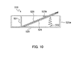
- FIGS. 8-10 are cross-sectional side views showing an example of a typical paper feed cassette 510.
- the paper feed cassette 510 includes a paper support plate 528 on which a stack of paper 526 is placed.
- the paper support plate 528 is configured to be swung by a biasing member, such as a spring 532, so that a downstream portion in a paper conveyance direction (a right side of FIG. 8 ) thereof is moved upward and downward.
- the stack of paper 526 placed on the paper support plate 528 of the paper feed cassette 510 is pressed against a pickup roller 529 which is provided on the apparatus body at a predetermined pressure which is exerted by the paper support plate 528 being urged upward by the spring 532.
- the pickup roller 529 and a feed roller 530a of a feed roller pair 530 are driven to rotate in a direction indicated by an arrow in FIG. 8 .
- the feed roller pair 530 includes the feed roller 530a and a separating roller 530b.
- the separating roller 530b is pressed against or withdrawn from the feed roller 530a.
- the separating roller 530b includes a torque limiter. Therefore, only when the rotational load exceeds a predetermined torque, the separating roller 530b is rotated by friction drive depending on the rotation of the feed roller 530a. Only the topmost sheet is separated by the separating roller 530b from the sheets of the paper 526 fed to the feed roller pair 530 and is then conveyed to a paper conveyance path 511.
- a trailing edge cursor 531 for evening or aligning the trailing edges of sheets of paper 526 is provided in a cassette base 525 and allowed to move along the paper conveyance direction (the left-right direction in FIGS. 8-10 ).
- a limiting protrusion 525b for limiting the upward movement of the paper support plate 528 is provided on a wall portion 525a of the cassette base 525. Therefore, as shown in FIG. 9 , when there is a large stack of paper 526, the limiting protrusion 525b presses the paper 526 so that the paper 526 and the paper support plate 528 are restrained from sticking out above the paper feed cassette 510.
- the pickup roller 529 is rotated to feed the paper 526 while being situated in a lower position to press the paper 526. At this time, the paper 526 is pressed down by the pickup roller 529, and therefore, does not come into contact with the limiting protrusion 525b. Therefore, the skew of the paper 526 is reduced.
- the inclination angle of the paper support plate 528 that is in contact with the limiting protrusion 525b is large.
- the paper support plate 528 reaches the maximum height. In this case, the paper support plate 528 sticks out above the paper feed cassette 510. Therefore, when the paper feed cassette 510 is inserted into or pulled out of the body of the image forming apparatus, the paper 526 and the paper support plate 528 touch the frame of the apparatus body. Note that if the size of the paper support plate 528 is reduced, the inclination angle of the paper support plate 528 increases, resulting in a higher maximum height of the paper support plate 528.
- a recording medium containing cassette is removably mounted in a body of an image forming apparatus.
- the recording medium containing cassette includes a recording medium support plate, a biasing member, and a width cursor.
- a stack of recording media is placed on the recording medium support plate.
- the biasing member biases upward the recording medium support plate.
- the width cursor positions the stack of recording media in a widthwise direction perpendicular to a conveyance direction of the recording medium.
- the recording medium support plate is allowed to swing so that a downstream portion in the conveyance direction of the recording medium support plate is moved upward and downward.
- the width cursor includes a first limiting portion and a second limiting portion.
- the first limiting portion limits the upward movement of the recording medium support plate when the recording medium containing cassette is outside the body of the image forming apparatus and an amount of the stack of recording media is larger than a predetermined value.
- the second limiting portion limits the upward movement of the recording medium support plate when the recording medium containing cassette is outside the body of the image forming apparatus and the amount of the stack of recording media is smaller than the predetermined value.
- an image forming apparatus includes a recording medium containing cassette and an image forming unit.
- the recording medium containing cassette is removably mounted in a body of the image forming apparatus.
- the image forming unit forms an image on the recording medium.
- the recording medium containing cassette includes a recording medium support platem a biasing member, and a width cursor.
- the recording medium support plate is configured to allow a stack of recording media to be placed thereon.
- the biasing member is configured to bias upward the recording medium support plate.
- the width cursor is configured to position the stack of recording media in a widthwise direction perpendicular to a conveyance direction of the recording medium.
- the recording medium support plate is allowed to swing so that a downstream portion in the conveyance direction of the recording medium support plate is moved upward and downward, raised.
- the width cursor includes a first limiting portion and a second limiting portion.
- the first limiting portion is configured to limit the upward movement of the recording medium support plate when the recording medium containing cassette is outside the body of the image forming apparatus and an amount of the stack of recording media is larger than a predetermined value.
- the second limiting portion is configured to limit the upward movement of the recording medium support plate when the recording medium containing cassette is outside the body of the image forming apparatus and the amount of the stack of recording media is smaller than the predetermined value.
- FIG. 1 An image forming apparatus 100 including a paper feed cassette (recording medium containing cassette) 10 according to one embodiment of the present disclosure will be described with reference to FIGS. 1-7 .
- the image forming apparatus 100 is, for example, a tandem color photocopier.
- four image forming sections Pa, Pb, Pc, and Pd are sequentially arranged from left to right in FIG. 1 .
- the image forming sections Pa-Pd which correspond to images of different four colors (yellow, magenta, cyan, and black), sequentially form yellow, magenta, cyan, and black images, respectively, by performing charging, exposing, developing, and transferring steps.
- the image forming section Pa includes a photosensitive drum 1a which bears a yellow visible image (toner image).
- the image forming section Pb includes a photosensitive drum 1b which bears a magenta visible image (toner image).
- the image forming section Pc includes a photosensitive drum 1c which bears a cyan visible image (toner image).
- the image forming section Pd includes a photosensitive drum 1d which bears a black visible image (toner image).
- An intermediate transfer belt 8 is provided adjacent to the image forming sections Pa-Pd. The intermediate transfer belt 8 rotates counterclockwise in FIG. 1 .
- the toner images on the photosensitive drums 1a-1d are sequentially transferred to and superimposed together on the intermediate transfer belt 8 which is in contact with the photosensitive drums 1a-1d.
- the toner images superimposed together on the intermediate transfer belt 8 are transferred to paper 26 by an action of a second-order transfer roller 9, and are then fixed to the paper 26 by a fixing device 7.
- the paper 26 is discharged from the body of the image forming apparatus 100.
- An image forming process is performed on each of the photosensitive drums 1a-1d while the photosensitive drums 1a-1d are rotated clockwise in FIG. 1 .
- the paper 26 is an example of a sheet-like recording medium.
- the paper 26 to which a toner image is to be transferred is contained in the paper feed cassette 10 which is provided in a lower portion of the body of the image forming apparatus 100.
- a stack of sheets of paper 26 is placed on a paper support plate (recording medium support plate) 28 of the paper feed cassette 10 (a stack of sheets of paper or a stack of recording media may be a single sheet of paper or a single recording medium).
- the feed of the paper 26 is started by rotating the pickup roller 29 while the upper surface of the paper 26 is pressed against the pickup roller 29 at a predetermined pressure.
- a feed roller pair 30 separates only the topmost sheet from the sheets of the paper 26, and then conveys that sheet toward a paper conveyance path 11.
- the paper 26 is passed through the paper conveyance path 11 to reach a registration roller pair 14, and is then conveyed to a nip portion between the second-order transfer roller 9 and a drive roller 13 of the intermediate transfer belt 8 in accordance with the timing of image formation.
- a cleaning blade 17 is provided downstream of the second-order transfer roller 9 in the direction of movement of the intermediate transfer belt 8.
- the cleaning blade 17 removes residual toner from a surface of the intermediate transfer belt 8.
- An image capture section 20 includes a scanning optical system, a condenser lens, a charge coupled device (CCD) sensor (none shown), etc.
- the image capture section 20 captures and converts an image of an original into image data.
- CCD charge coupled device
- the image forming section Pa includes the photosensitive drum 1a, a charging device 2a, a developing device 3a, and a cleaning device 5a.
- the image forming section Pb includes the photosensitive drum 1b, a charging device 2b, a developing device 3b, and a cleaning device 5b.
- the image forming section Pc includes the photosensitive drum 1c, a charging device 2c, a developing device 3c, and a cleaning device 5c.
- the image forming section Pd includes the photosensitive drum 1d, a charging device 2d, a developing device 3d, and a cleaning device 5d.
- a single exposing device 4 is used for all of the image forming sections Pa-Pd.
- the image forming sections Pa-Pd, the exposing device 4, the intermediate transfer belt 8, an idler roller 12, the drive roller 13, first-order transfer rollers 6a-6d, the second-order transfer roller 9, and the cleaning blade 17 form an image forming unit.
- the image forming unit forms an image on the paper 26.
- the paper feed cassette 10 is removably mounted in the body of the image forming apparatus 100.
- a direction in which the paper feed cassette 10 is inserted into the image forming apparatus 100 is indicated by an arrow A.
- a direction in which the paper feed cassette 10 is pulled out is indicated by an arrow A#.
- a direction in which the paper feed cassette 10 feeds paper is indicated by an arrow B.
- the conveyance direction of the paper 26 in the paper feed cassette 10 is hereinafter referred to as a "paper conveyance direction.”
- Wall portions 25a-25d are provided in an upright position at four side edge portions of a cassette base 25.
- the cassette base 25 serves as a housing of the paper feed cassette 10.
- a cassette cover 33 is attached to the wall portion 25c, which is located on the upstream side of the paper feed cassette 10 in a direction in which the paper feed cassette 10 is inserted.
- a pull handle 35 which is used to insert and remove the paper feed cassette 10 is provided at a middle portion of the cassette cover 33.
- a guide rail 40a and a guide rail 40b are provided on the wall portions 25a and 25d, respectively, which are parallel to the direction in which the paper feed cassette 10 is inserted or pulled out (the direction indicated by the arrow A or the direction indicated by the arrow A#).
- Two rail support portions (not shown) which support the guide rails 40a and 40b for sliding movement are provided on the body of the image forming apparatus 100.
- the paper support plate 28, on which the paper 26 (see FIG. 1 ) is placed, is allowed to swing about swing shafts (pivots) 28a provided at opposite ends in the directions of the arrows A and A#.
- base end portions of the paper support plate 28 are rotatably supported by the swing shafts 28a.
- a portion (leading end portion) of the paper support plate 28 which is located downstream of the base end portion of the paper support plate 28 in the paper feed direction (indicated by the arrow B) is moved upward and downward in relation to the cassette base 25, for example, by a compression coil spring 32 (see FIG. 5 ).
- the paper support plate 28 is allowed to swing so that the downstream portion (leading end portion) of the paper support plate 28 in the paper feed direction (paper conveyance direction) is moved upward and downward.
- the compression coil spring 32 is an example of a biasing member which biases upward the paper support plate 28.
- a pair of widthwise edge aligning cursors (width cursor or widthwise positioning member) 37a and 37b are provided at opposite ends of the paper support plate 28 in a widthwise direction (the directions indicated by the arrows A and A#, i.e., a direction perpendicular to the paper feed direction) of the paper support plate 28.
- the widthwise edge aligning cursors 37a and 37b position the stack of paper 26 placed on the paper support plate 28 in the widthwise direction (the directions indicated by the arrows A and A#).
- the widthwise edge aligning cursors 37a and 37b position the stack of paper 26 along the widthwise direction perpendicular to the paper conveyance direction.
- the widthwise edge aligning cursors 37a and 37b are each allowed to reciprocally move along guide rails (not shown) provided on the cassette base 25 in the widthwise direction of the paper 26.
- the widthwise edge aligning cursors 37a and 37b extend in the paper feed direction.
- the widthwise edge aligning cursors 37a and 37b have opposed wall portions (paper contact wall portions) with which edges of the paper 26 come into contact.
- the widthwise edge aligning cursors 37a and 37b have a rack portion 38a and a rack portion 38b, respectively, which extend in the directions indicated by the arrows A and A#.
- the two rack portions 38a and 38b are engaged with a pinion gear 39. Therefore, when one of the widthwise edge aligning cursors 37a and 37b is moved (slid) in the widthwise direction of the paper 26, the resultant drive force is transmitted via the pinion gear 39 to the other widthwise edge aligning cursor 37a or 37b. As a result, the widthwise edge aligning cursors 37a and 37b are moved (slid) in the opposite directions by the same distance.
- the paper contact wall portions of the widthwise edge aligning cursors 37a and 37b each have a first limiting protrusion (first limiting portion) 41 and a second limiting protrusion (second limiting portion) 42.
- the first and second limiting protrusions 41 and 42 are provided at downstream end parts of the widthwise edge aligning cursors 37a and 37b in the paper conveyance direction (direction indicated by the arrow B).
- the first limiting protrusions 41 are provided at uppermost portions of the widthwise edge aligning cursors 37a and 37b, protruding from the widthwise edge aligning cursors 37a and 37b in the widthwise direction toward a middle of the paper feed cassette 10.
- the second limiting protrusions 42 protrude from the widthwise edge aligning cursors 37a and 37b downstream in the paper conveyance direction.
- the second limiting protrusion 42 is provided in a lower position than that of the first limiting protrusion 41 and downstream of the first limiting protrusion 41 in the paper conveyance direction.
- the second limiting protrusion 42 is arranged external to the paper 26 placed on the paper support plate 28.
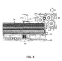
- FIG. 5 when the pickup roller 29 is situated in a lower position to press the paper 26, the first limiting protrusions 41 are not in contact with the paper 26.
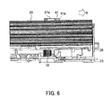
- FIG. 6 when the pickup roller 29 is situated in a higher position, then if an amount of the stack of paper 26 is larger than a predetermined value, the first limiting protrusion 41 presses the paper 26.
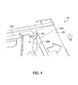
- FIG. 7 when the pickup roller 29 is situated in the higher position, then if the amount of the stack of paper 26 is smaller than the predetermined value (this encompasses the absence of paper on the paper support plate 28), the second limiting protrusions 42 press a contact portion 28b (see FIG. 4 ) of the paper support plate 28.
- FIGS. 6 and 7 show the paper feed cassette 10 which is removed from the body of the image forming apparatus 100.
- a trailing edge cursor 31 is provided to even or align the trailing edges of sheets of paper 26. Since the paper 26 is fed in the direction indicated by the arrow B toward the paper conveyance path 11 (see FIG. 1 ), the trailing edge cursor 31 is disposed to be movable reciprocally along a guide rail (not shown) provided on the cassette base 25 in parallel to the paper conveyance direction (the direction indicated by the arrow B).
- the paper 26 can be contained at a predetermined position in the paper feed cassette 10.
- the first limiting protrusion 41 has a flat surface 41a (see FIGS. 5-7 ). The flat surface 41a extends along a horizontal direction. When the amount of the stack of paper 26 is larger than the predetermined value, the flat surface 41a is in contact with the paper 26.
- the second limiting protrusion 42 has a sloping surface 42a (see FIGS. 4 and 7 ).
- the sloping surface 42a slopes upward toward the downstream side in the conveyance direction (the direction indicated by the arrow B).
- the contact portion 28b of the paper support plate 28 is a sloping surface which slopes upward toward the downstream side in the conveyance direction, and extends in the widthwise direction.
- the widthwise edge aligning cursors 37a and 37b each have the first and second limiting protrusions 41 and 42.
- the first limiting protrusion 41 limits the upward movement of the paper support plate 28 when the paper feed cassette 10 is outside the body of the image forming apparatus 100 and the amount of the stack of paper 26 is larger than the predetermined value.
- the second limiting protrusion 42 limits the upward movement of the paper support plate 28 when the paper feed cassette 10 is outside the body of the image forming apparatus 100 and the amount of the stack of paper 26 is smaller than the predetermined value.
- the upward movement of the paper support plate 28 can be limited. Therefore, the paper 26 and the paper support plate 28 can be restrained from sticking out above the paper feed cassette 10. As a result, when the paper feed cassette 10 is inserted into and removed from the body of the image forming apparatus 100, the paper 26 and the paper support plate 28 can be restrained from touching the frame of the body of the image forming apparatus 100.
- the first limiting protrusion 41 presses the paper 26 when the amount of the stack of paper 26 is larger than the predetermined value
- the second limiting protrusion 42 presses the paper support plate 28 when the amount of the stack of paper 26 is smaller than the predetermined value. Therefore, when the amount of the stack of paper 26 is larger than the predetermined value, the first limiting protrusion 41 can easily restrain the upward movement of the paper support plate 28, and when the amount of the stack of paper 26 is smaller than the predetermined value, the second limiting protrusion 42 can easily restrain the upward movement of the paper support plate 28.
- the first limiting protrusion 41 protrudes from each of the widthwise edge aligning cursors 37a and 37b along the widthwise direction toward a middle of the paper feed cassette 10.
- the second limiting protrusion 42 protrudes from each of the widthwise edge aligning cursors 37a and 37b downstream in the paper conveyance direction. Therefore, the paper 26 can be easily pressed by the first limiting protrusion 41, and the paper support plate 28 can be easily pressed by the second limiting protrusion 42.
- the second limiting protrusion 42 is provided in a lower position than that of the first limiting protrusion 41. Therefore, when the amount of the stack of paper 26 is smaller than the predetermined value, the paper 26 and the paper support plate 28 can be easily restrained from sticking out above the paper feed cassette 10.
- the widthwise edge aligning cursors 37a and 37b which are movable in the widthwise direction are provided at the opposite ends in the widthwise direction of the paper support plate 28.
- the present disclosure is not limited to this.
- a widthwise edge aligning cursor e.g., the widthwise edge aligning cursor 37a
- the widthwise edge aligning cursor and a wall portion e.g., the wall portion 25c
- the first and second limiting protrusions 41 and 42 may be provided on the wall portion which is a widthwise positioning member.
- the two first limiting protrusions 41 and the two second limiting protrusions 42 are provided.
- the present disclosure is not limited to this.
- only one first limiting protrusion 41 and only one second limiting protrusion 42 may be provided.
- the paper feed cassette 10 is inserted into and removed from the body of the image forming apparatus 100 in the direction perpendicular to the paper conveyance direction.
- the present disclosure is not limited to this.
- the present disclosure is also applicable to a paper feed cassette which is inserted into and removed from the body of the image forming apparatus 100 in a direction parallel to the paper conveyance direction.
Landscapes
- Engineering & Computer Science (AREA)
- Mechanical Engineering (AREA)
- Physics & Mathematics (AREA)
- General Physics & Mathematics (AREA)
- Sheets, Magazines, And Separation Thereof (AREA)
Abstract
Description
- The present disclosure relates to recording medium containing cassettes for containing sheet-like recording media, which are used in image forming apparatuses, such as digital photocopiers and laser printers, and image forming apparatuses including such a recording medium containing cassette.
- A paper feed cassette (recording medium containing cassette) which is removably mounted in the body of an image forming apparatus has been commonly used. The paper feed cassette contains a stack of sheets of paper (recording medium). The paper feed cassette feeds paper to an image forming section in the body of the image forming apparatus in accordance with image forming operation, one sheet at a time. The paper feed cassette includes a paper support plate (recording medium support plate) on which a stack of paper is placed. The paper support plate is allowed to swing.
- A typical configuration of the paper feed cassette will be described.
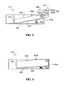
FIGS. 8-10 are cross-sectional side views showing an example of a typicalpaper feed cassette 510. As shown inFIG. 8 , thepaper feed cassette 510 includes apaper support plate 528 on which a stack ofpaper 526 is placed. Thepaper support plate 528 is configured to be swung by a biasing member, such as aspring 532, so that a downstream portion in a paper conveyance direction (a right side ofFIG. 8 ) thereof is moved upward and downward. - The stack of
paper 526 placed on thepaper support plate 528 of thepaper feed cassette 510 is pressed against apickup roller 529 which is provided on the apparatus body at a predetermined pressure which is exerted by thepaper support plate 528 being urged upward by thespring 532. At this time, if a print start button of the image forming apparatus is pushed or switched on, thepickup roller 529 and afeed roller 530a of afeed roller pair 530 are driven to rotate in a direction indicated by an arrow inFIG. 8 . - Typically, several top sheets of
paper 526 placed on thepaper support plate 528 are fed by thepickup roller 529 to thefeed roller pair 530. Thefeed roller pair 530 includes thefeed roller 530a and a separatingroller 530b. The separatingroller 530b is pressed against or withdrawn from thefeed roller 530a. The separatingroller 530b includes a torque limiter. Therefore, only when the rotational load exceeds a predetermined torque, the separatingroller 530b is rotated by friction drive depending on the rotation of thefeed roller 530a. Only the topmost sheet is separated by the separatingroller 530b from the sheets of thepaper 526 fed to thefeed roller pair 530 and is then conveyed to apaper conveyance path 511. Atrailing edge cursor 531 for evening or aligning the trailing edges of sheets ofpaper 526 is provided in acassette base 525 and allowed to move along the paper conveyance direction (the left-right direction inFIGS. 8-10 ). - In the
paper feed cassette 510, alimiting protrusion 525b for limiting the upward movement of thepaper support plate 528 is provided on awall portion 525a of thecassette base 525. Therefore, as shown inFIG. 9 , when there is a large stack ofpaper 526, thelimiting protrusion 525b presses thepaper 526 so that thepaper 526 and thepaper support plate 528 are restrained from sticking out above thepaper feed cassette 510. - During paper feed operation, the
pickup roller 529 is rotated to feed thepaper 526 while being situated in a lower position to press thepaper 526. At this time, thepaper 526 is pressed down by thepickup roller 529, and therefore, does not come into contact with thelimiting protrusion 525b. Therefore, the skew of thepaper 526 is reduced. - When there is a small stack of
paper 526 in thepaper feed cassette 510, as shown inFIG. 10 , the inclination angle of thepaper support plate 528 that is in contact with thelimiting protrusion 525b is large. When there is no stack ofpaper 526, thepaper support plate 528 reaches the maximum height. In this case, thepaper support plate 528 sticks out above thepaper feed cassette 510. Therefore, when thepaper feed cassette 510 is inserted into or pulled out of the body of the image forming apparatus, thepaper 526 and thepaper support plate 528 touch the frame of the apparatus body. Note that if the size of thepaper support plate 528 is reduced, the inclination angle of thepaper support plate 528 increases, resulting in a higher maximum height of thepaper support plate 528. - According to a first aspect of the present disclosure, a recording medium containing cassette is removably mounted in a body of an image forming apparatus. The recording medium containing cassette includes a recording medium support plate, a biasing member, and a width cursor. A stack of recording media is placed on the recording medium support plate. The biasing member biases upward the recording medium support plate. The width cursor positions the stack of recording media in a widthwise direction perpendicular to a conveyance direction of the recording medium. The recording medium support plate is allowed to swing so that a downstream portion in the conveyance direction of the recording medium support plate is moved upward and downward. The width cursor includes a first limiting portion and a second limiting portion. The first limiting portion limits the upward movement of the recording medium support plate when the recording medium containing cassette is outside the body of the image forming apparatus and an amount of the stack of recording media is larger than a predetermined value. The second limiting portion limits the upward movement of the recording medium support plate when the recording medium containing cassette is outside the body of the image forming apparatus and the amount of the stack of recording media is smaller than the predetermined value.
- According to a second aspect of the present disclosure, an image forming apparatus includes a recording medium containing cassette and an image forming unit. The recording medium containing cassette is removably mounted in a body of the image forming apparatus. The image forming unit forms an image on the recording medium. The recording medium containing cassette includes a recording medium support platem a biasing member, and a width cursor. The recording medium support plate is configured to allow a stack of recording media to be placed thereon. The biasing member is configured to bias upward the recording medium support plate. The width cursor is configured to position the stack of recording media in a widthwise direction perpendicular to a conveyance direction of the recording medium. The recording medium support plate is allowed to swing so that a downstream portion in the conveyance direction of the recording medium support plate is moved upward and downward, raised. The width cursor includes a first limiting portion and a second limiting portion. The first limiting portion is configured to limit the upward movement of the recording medium support plate when the recording medium containing cassette is outside the body of the image forming apparatus and an amount of the stack of recording media is larger than a predetermined value. The second limiting portion is configured to limit the upward movement of the recording medium support plate when the recording medium containing cassette is outside the body of the image forming apparatus and the amount of the stack of recording media is smaller than the predetermined value.
-
-
FIG. 1 is a cross-sectional view schematically showing a structure of an image forming apparatus including a paper feed cassette according to one embodiment of the present disclosure. -
FIG. 2 is a perspective view showing a structure of the paper feed cassette of the embodiment of the present disclosure. -
FIG. 3 is a plan view showing a structure of the paper feed cassette of the embodiment of the present disclosure. -
FIG. 4 is an enlarged perspective view showing structures of first and second limiting protrusions and their surroundings of the paper feed cassette of the embodiment of the present disclosure. -
FIG. 5 is a cross-sectional view showing a structure of the paper feed cassette of the embodiment of the present disclosure and structures of a pickup roller and its surroundings. -
FIG. 6 is a cross-sectional view showing the paper feed cassette of the embodiment of the present disclosure when it contains a stack of paper whose amount is larger than a predetermined value. -
FIG. 7 is a cross-sectional view showing the paper feed cassette of the embodiment of the present disclosure when it contains a stack of paper whose amount is smaller than the predetermined value. -
FIG. 8 is a cross-sectional side view showing a typical paper feed cassette. -
FIG. 9 is a cross-sectional view showing the typical paper feed cassette when it contains a stack of paper whose amount is larger than a predetermined value. -
FIG. 10 is a cross-sectional view showing the typical paper feed cassette when it contains a stack of paper whose amount is smaller than the predetermined value. - An embodiment of the present disclosure will now be described with reference to the accompanying drawings.
- An
image forming apparatus 100 including a paper feed cassette (recording medium containing cassette) 10 according to one embodiment of the present disclosure will be described with reference toFIGS. 1-7 . As shown inFIG. 1 , theimage forming apparatus 100 is, for example, a tandem color photocopier. In the body of theimage forming apparatus 100, four image forming sections Pa, Pb, Pc, and Pd are sequentially arranged from left to right inFIG. 1 . The image forming sections Pa-Pd, which correspond to images of different four colors (yellow, magenta, cyan, and black), sequentially form yellow, magenta, cyan, and black images, respectively, by performing charging, exposing, developing, and transferring steps. - The image forming section Pa includes a photosensitive drum 1a which bears a yellow visible image (toner image). The image forming section Pb includes a
photosensitive drum 1b which bears a magenta visible image (toner image). The image forming section Pc includes a photosensitive drum 1c which bears a cyan visible image (toner image). The image forming section Pd includes a photosensitive drum 1d which bears a black visible image (toner image). Anintermediate transfer belt 8 is provided adjacent to the image forming sections Pa-Pd. Theintermediate transfer belt 8 rotates counterclockwise inFIG. 1 . - The toner images on the photosensitive drums 1a-1d are sequentially transferred to and superimposed together on the
intermediate transfer belt 8 which is in contact with the photosensitive drums 1a-1d. The toner images superimposed together on theintermediate transfer belt 8 are transferred topaper 26 by an action of a second-order transfer roller 9, and are then fixed to thepaper 26 by a fixingdevice 7. After the fixation of the toner images, thepaper 26 is discharged from the body of theimage forming apparatus 100. An image forming process is performed on each of the photosensitive drums 1a-1d while the photosensitive drums 1a-1d are rotated clockwise inFIG. 1 . Thepaper 26 is an example of a sheet-like recording medium. - The
paper 26 to which a toner image is to be transferred is contained in thepaper feed cassette 10 which is provided in a lower portion of the body of theimage forming apparatus 100. A stack of sheets ofpaper 26 is placed on a paper support plate (recording medium support plate) 28 of the paper feed cassette 10 (a stack of sheets of paper or a stack of recording media may be a single sheet of paper or a single recording medium). The feed of thepaper 26 is started by rotating thepickup roller 29 while the upper surface of thepaper 26 is pressed against thepickup roller 29 at a predetermined pressure. Afeed roller pair 30 separates only the topmost sheet from the sheets of thepaper 26, and then conveys that sheet toward apaper conveyance path 11. Thepaper 26 is passed through thepaper conveyance path 11 to reach aregistration roller pair 14, and is then conveyed to a nip portion between the second-order transfer roller 9 and adrive roller 13 of theintermediate transfer belt 8 in accordance with the timing of image formation. - A
cleaning blade 17 is provided downstream of the second-order transfer roller 9 in the direction of movement of theintermediate transfer belt 8. Thecleaning blade 17 removes residual toner from a surface of theintermediate transfer belt 8. - An
image capture section 20 includes a scanning optical system, a condenser lens, a charge coupled device (CCD) sensor (none shown), etc. Theimage capture section 20 captures and converts an image of an original into image data. - Next, the image forming sections Pa-Pd will be described. The image forming section Pa includes the photosensitive drum 1a, a
charging device 2a, a developingdevice 3a, and acleaning device 5a. The image forming section Pb includes thephotosensitive drum 1b, acharging device 2b, a developingdevice 3b, and acleaning device 5b. The image forming section Pc includes the photosensitive drum 1c, acharging device 2c, a developingdevice 3c, and acleaning device 5c. The image forming section Pd includes the photosensitive drum 1d, acharging device 2d, a developing device 3d, and acleaning device 5d. A single exposing device 4 is used for all of the image forming sections Pa-Pd. - The image forming sections Pa-Pd, the exposing device 4, the
intermediate transfer belt 8, anidler roller 12, thedrive roller 13, first-order transfer rollers 6a-6d, the second-order transfer roller 9, and thecleaning blade 17 form an image forming unit. The image forming unit forms an image on thepaper 26. - Next, a configuration of the
paper feed cassette 10 will be described. Thepaper feed cassette 10 is removably mounted in the body of theimage forming apparatus 100. InFIG. 2 , a direction in which thepaper feed cassette 10 is inserted into theimage forming apparatus 100 is indicated by an arrow A. A direction in which thepaper feed cassette 10 is pulled out is indicated by an arrow A#. A direction in which thepaper feed cassette 10 feeds paper (i.e., a direction in which thepaper 26 or a recording medium is conveyed) is indicated by an arrow B. The conveyance direction of thepaper 26 in thepaper feed cassette 10 is hereinafter referred to as a "paper conveyance direction."Wall portions 25a-25d are provided in an upright position at four side edge portions of acassette base 25. Thecassette base 25 serves as a housing of thepaper feed cassette 10. - A
cassette cover 33 is attached to thewall portion 25c, which is located on the upstream side of thepaper feed cassette 10 in a direction in which thepaper feed cassette 10 is inserted. A front surface (on a lower side ofFIG. 3 ) of thecassette cover 33, which is exposed to the outside, is a part of an outer surface of the body of the image forming apparatus 100 (seeFIG. 1 ). Apull handle 35 which is used to insert and remove thepaper feed cassette 10 is provided at a middle portion of thecassette cover 33. - A
guide rail 40a and aguide rail 40b are provided on thewall portions paper feed cassette 10 is inserted or pulled out (the direction indicated by the arrow A or the direction indicated by the arrow A#). Two rail support portions (not shown) which support theguide rails image forming apparatus 100. By causing theguide rails paper feed cassette 10 can be inserted into and pulled out of the body of theimage forming apparatus 100. - The
paper support plate 28, on which the paper 26 (seeFIG. 1 ) is placed, is allowed to swing about swing shafts (pivots) 28a provided at opposite ends in the directions of the arrows A and A#. In other words, base end portions of thepaper support plate 28 are rotatably supported by theswing shafts 28a. A portion (leading end portion) of thepaper support plate 28 which is located downstream of the base end portion of thepaper support plate 28 in the paper feed direction (indicated by the arrow B) is moved upward and downward in relation to thecassette base 25, for example, by a compression coil spring 32 (seeFIG. 5 ). In other words, thepaper support plate 28 is allowed to swing so that the downstream portion (leading end portion) of thepaper support plate 28 in the paper feed direction (paper conveyance direction) is moved upward and downward. Thecompression coil spring 32 is an example of a biasing member which biases upward thepaper support plate 28. - A pair of widthwise edge aligning cursors (width cursor or widthwise positioning member) 37a and 37b are provided at opposite ends of the
paper support plate 28 in a widthwise direction (the directions indicated by the arrows A and A#, i.e., a direction perpendicular to the paper feed direction) of thepaper support plate 28. The widthwiseedge aligning cursors paper 26 placed on thepaper support plate 28 in the widthwise direction (the directions indicated by the arrows A and A#). In other words, the widthwiseedge aligning cursors paper 26 along the widthwise direction perpendicular to the paper conveyance direction. - The widthwise
edge aligning cursors cassette base 25 in the widthwise direction of thepaper 26. The widthwiseedge aligning cursors edge aligning cursors paper 26 come into contact. - The widthwise
edge aligning cursors rack portion 38a and arack portion 38b, respectively, which extend in the directions indicated by the arrows A and A#. The tworack portions pinion gear 39. Therefore, when one of the widthwiseedge aligning cursors paper 26, the resultant drive force is transmitted via thepinion gear 39 to the other widthwiseedge aligning cursor edge aligning cursors - As shown in
FIGS. 2 and4 , the paper contact wall portions of the widthwiseedge aligning cursors protrusions edge aligning cursors - The first limiting
protrusions 41 are provided at uppermost portions of the widthwiseedge aligning cursors edge aligning cursors paper feed cassette 10. - The second limiting
protrusions 42 protrude from the widthwiseedge aligning cursors protrusion 42 is provided in a lower position than that of the first limitingprotrusion 41 and downstream of the first limitingprotrusion 41 in the paper conveyance direction. The second limitingprotrusion 42 is arranged external to thepaper 26 placed on thepaper support plate 28. - As shown in
FIG. 5 , when thepickup roller 29 is situated in a lower position to press thepaper 26, the first limitingprotrusions 41 are not in contact with thepaper 26. On the other hand, as shown inFIG. 6 , when thepickup roller 29 is situated in a higher position, then if an amount of the stack ofpaper 26 is larger than a predetermined value, the first limitingprotrusion 41 presses thepaper 26. As shown inFIG. 7 , when thepickup roller 29 is situated in the higher position, then if the amount of the stack ofpaper 26 is smaller than the predetermined value (this encompasses the absence of paper on the paper support plate 28), the second limitingprotrusions 42 press acontact portion 28b (seeFIG. 4 ) of thepaper support plate 28. Note thatFIGS. 6 and7 show thepaper feed cassette 10 which is removed from the body of theimage forming apparatus 100. - As shown in
FIG. 2 , a trailingedge cursor 31 is provided to even or align the trailing edges of sheets ofpaper 26. Since thepaper 26 is fed in the direction indicated by the arrow B toward the paper conveyance path 11 (seeFIG. 1 ), the trailingedge cursor 31 is disposed to be movable reciprocally along a guide rail (not shown) provided on thecassette base 25 in parallel to the paper conveyance direction (the direction indicated by the arrow B). - If the widthwise
edge aligning cursors edge cursor 31 are moved to positions corresponding to the size of placed paper, thepaper 26 can be contained at a predetermined position in thepaper feed cassette 10. - As shown in
FIG. 6 , in theimage forming apparatus 100 including thepaper feed cassette 10 of this embodiment, if the amount of the stack ofpaper 26 is larger than the predetermined value, then when thepickup roller 29 is situated in the higher position, the topmost sheet ofpaper 26 comes into contact with the first limitingprotrusion 41. In other words, when the amount of the stack ofpaper 26 is larger than the predetermined value, the first limitingprotrusion 41 is in contact with thepaper 26. As a result, the upward movement of thepaper support plate 28 is limited, and therefore, thepaper support plate 28 and thepaper 26 are restrained from sticking out above thepaper feed cassette 10. Note that the first limitingprotrusion 41 has aflat surface 41a (seeFIGS. 5-7 ). Theflat surface 41a extends along a horizontal direction. When the amount of the stack ofpaper 26 is larger than the predetermined value, theflat surface 41a is in contact with thepaper 26. - On the other hand, as shown in
FIG. 7 , if the amount of the stack ofpaper 26 is smaller than the predetermined value, then when thepickup roller 29 is situated in the higher position, the downstream portion (leading end portion) in the paper conveyance direction of thepaper support plate 28 is moved upward until thecontact portion 28b of thepaper support plate 28 comes into contact with the second limitingprotrusion 42. In other words, when the amount of the stack ofpaper 26 is smaller than the predetermined value, the second limitingprotrusion 42 is in contact with thepaper support plate 28. As a result, the upward movement of thepaper support plate 28 is limited, and therefore, thepaper support plate 28 and thepaper 26 are restrained from sticking out above thepaper feed cassette 10. Note that the second limitingprotrusion 42 has asloping surface 42a (seeFIGS. 4 and7 ). Thesloping surface 42a slopes upward toward the downstream side in the conveyance direction (the direction indicated by the arrow B). On the other hand, thecontact portion 28b of thepaper support plate 28 is a sloping surface which slopes upward toward the downstream side in the conveyance direction, and extends in the widthwise direction. When the amount of the stack ofpaper 26 is smaller than the predetermined value, thesloping surface 42a is in contact with thecontact portion 28b. - Note that if the second limiting
protrusion 42 is not provided, thepaper 26 is lifted up to a position indicated by a dash-dot-dot line inFIG. 7 , and therefore, thepaper 26 and thepaper support plate 28 stick out above thepaper feed cassette 10. As described above, in this embodiment, the widthwiseedge aligning cursors protrusions protrusion 41 limits the upward movement of thepaper support plate 28 when thepaper feed cassette 10 is outside the body of theimage forming apparatus 100 and the amount of the stack ofpaper 26 is larger than the predetermined value. The second limitingprotrusion 42 limits the upward movement of thepaper support plate 28 when thepaper feed cassette 10 is outside the body of theimage forming apparatus 100 and the amount of the stack ofpaper 26 is smaller than the predetermined value. - Therefore, both when the amount of the stack of
paper 26 is larger than the predetermined value and when the amount of the stack ofpaper 26 is smaller than the predetermined value, the upward movement of thepaper support plate 28 can be limited. Therefore, thepaper 26 and thepaper support plate 28 can be restrained from sticking out above thepaper feed cassette 10. As a result, when thepaper feed cassette 10 is inserted into and removed from the body of theimage forming apparatus 100, thepaper 26 and thepaper support plate 28 can be restrained from touching the frame of the body of theimage forming apparatus 100. - As described above, the first limiting
protrusion 41 presses thepaper 26 when the amount of the stack ofpaper 26 is larger than the predetermined value, and the second limitingprotrusion 42 presses thepaper support plate 28 when the amount of the stack ofpaper 26 is smaller than the predetermined value. Therefore, when the amount of the stack ofpaper 26 is larger than the predetermined value, the first limitingprotrusion 41 can easily restrain the upward movement of thepaper support plate 28, and when the amount of the stack ofpaper 26 is smaller than the predetermined value, the second limitingprotrusion 42 can easily restrain the upward movement of thepaper support plate 28. - As described above, the first limiting
protrusion 41 protrudes from each of the widthwiseedge aligning cursors paper feed cassette 10. The second limitingprotrusion 42 protrudes from each of the widthwiseedge aligning cursors paper 26 can be easily pressed by the first limitingprotrusion 41, and thepaper support plate 28 can be easily pressed by the second limitingprotrusion 42. - As described above, the second limiting
protrusion 42 is provided in a lower position than that of the first limitingprotrusion 41. Therefore, when the amount of the stack ofpaper 26 is smaller than the predetermined value, thepaper 26 and thepaper support plate 28 can be easily restrained from sticking out above thepaper feed cassette 10. - The embodiment described above is considered to be illustrative in all respects and not restrictive, the scope of the present disclosure being indicated by the appended claims rather than by the foregoing description. The present disclosure includes all modifications and equivalents as defined by the appended claims.
- In the above embodiment, the widthwise
edge aligning cursors paper support plate 28. The present disclosure is not limited to this. For example, a widthwise edge aligning cursor (e.g., the widthwiseedge aligning cursor 37a) may be provided only at one end in the widthwise direction of thepaper support plate 28, and the widthwise edge aligning cursor and a wall portion (e.g., thewall portion 25c) of thecassette base 25 may be used to position thepaper 26 in the widthwise direction. In this case, the first and second limitingprotrusions - In the above embodiment, the two first limiting
protrusions 41 and the two second limitingprotrusions 42 are provided. The present disclosure is not limited to this. Alternatively, only one first limitingprotrusion 41 and only one second limitingprotrusion 42 may be provided. In the above embodiment, thepaper feed cassette 10 is inserted into and removed from the body of theimage forming apparatus 100 in the direction perpendicular to the paper conveyance direction. The present disclosure is not limited to this. For example, the present disclosure is also applicable to a paper feed cassette which is inserted into and removed from the body of theimage forming apparatus 100 in a direction parallel to the paper conveyance direction.
Claims (15)
- A recording medium containing cassette removably mounted in a body of an image forming apparatus, comprising:a recording medium support plate configured to allow a stack of recording media to be placed thereon;a biasing member configured to bias upward the recording medium support plate; anda width cursor configured to position the stack of recording media in a widthwise direction perpendicular to a conveyance direction of the recording medium, whereinthe recording medium support plate is allowed to swing so that a downstream portion in the conveyance direction of the recording medium support plate is moved upward and downward, raisedthe width cursor includesa first limiting portion configured to limit the upward movement of the recording medium support plate when the recording medium containing cassette is outside the body of the image forming apparatus and an amount of the stack of recording media is larger than a predetermined value, anda second limiting portion configured to limit the upward movement of the recording medium support plate when the recording medium containing cassette is outside the body of the image forming apparatus and the amount of the stack of recording media is smaller than the predetermined value.
- A recording medium containing cassette according to claim 1, wherein
the first limiting portion is in contact with the stack of recording media when the amount of the stack of recording media is larger than the predetermined value, and
the second limiting portion is in contact with the recording media support plate when the amount of the stack of the recording media is smaller than the predetermined value. - A recording medium containing cassette according to claim 2, wherein
The first limiting portion and the second limiting portion are provided at a downstream part of the width cursor in the conveyance direction. - A recording medium containing cassette according to claim 3, wherein
the first limiting portion protrudes from the width cursor along the widthwise direction toward a middle of the recording medium containing cassette, and
the second limiting portion protrudes from the width cursor downstream in the conveyance direction. - A recording medium containing cassette according to claim 4, wherein
the second limiting portion is arranged external to the recording medium placed on the recording medium support plate. - A recording medium containing cassette according to any one of claims 2-5, wherein
the second limiting portion is provided in a lower position than that of the first limiting portion. - A recording medium containing cassette according to any one of claims 2-6, wherein
the second limiting portion is provided downstream of the first limiting portion in the conveyance direction. - A recording medium containing cassette according to any one of claims 2-7, wherein
the first limiting portion has a flat surface configured to be in contact with the stack of recording media when the amount of the stack of recording media is larger than the predetermined value,
the flat surface extends in a horizontal direction,
the second limiting portion has a sloping surface,
the sloping surface slopes upward toward a downstream side in the conveyance direction,
the recording medium support plate has an contact portion extending in the widthwise direction,
the contact portion is a sloping surface which slopes upward toward the downstream side in the conveyance direction, and
the sloping surface of the second limiting portion is in contact with the contact portion when the amount of the stack of recording media is smaller than the predetermined value. - An image forming apparatus comprising:a recording medium containing cassette removably mounted in a body of an image forming apparatus; andan image forming unit configured to form an image on a recording medium,wherein the recording medium containing cassette includes:a recording medium support plate configured to allow a stack of recording media to be placed thereon;a biasing member configured to bias upward the recording medium support plate; anda width cursor configured to position the stack of recording media in a widthwise direction perpendicular to a conveyance direction of the recording medium,the recording medium support plate is allowed to swing so that a downstream portion in the conveyance direction of the recording medium support plate is moved upward and downward, raisedthe width cursor includes:a first limiting portion configured to limit the upward movement of the recording medium support plate when the recording medium containing cassette is outside the body of the image forming apparatus and an amount of the stack of recording media is larger than a predetermined value, anda second limiting portion configured to limit the upward movement of the recording medium support plate when the recording medium containing cassette is outside the body of the image forming apparatus and the amount of the stack of recording media is smaller than the predetermined value.
- An image forming apparatus according to claim 9, wherein
the first limiting portion is in contact with the stack of recording media when the amount of the stack of recording media is larger than the predetermined value, and
the second limiting portion is in contact with the recording media support plate when the amount of the stack of recording media is smaller than the predetermined value. - An image forming apparatus according to claim 10, wherein
The first limiting portion and the second limiting portion are provided at a downstream part of the width cursor in the conveyance direction. - An image forming apparatus according to claim 11, wherein
the first limiting portion protrudes from the width cursor along the widthwise direction toward a middle of the recording medium containing cassette, and
the second limiting portion protrudes from the width cursor downstream in the conveyance direction. - An image forming apparatus according to claim 12, wherein
the second limiting portion is arranged external to the recording medium placed on the recording medium support plate. - An image forming apparatus according to any one of claims 10-13, wherein
the second limiting portion is provided in a lower position than that of the first limiting portion. - An image forming apparatus according to any one of claims 10-14, wherein
the second limiting portion is provided downstream of the first limiting portion in the conveyance direction.
Applications Claiming Priority (1)
| Application Number | Priority Date | Filing Date | Title |
|---|---|---|---|
| JP2012277610A JP5779574B2 (en) | 2012-12-20 | 2012-12-20 | Recording medium storage cassette and image forming apparatus having the same |
Publications (3)
| Publication Number | Publication Date |
|---|---|
| EP2746856A2 true EP2746856A2 (en) | 2014-06-25 |
| EP2746856A3 EP2746856A3 (en) | 2017-11-22 |
| EP2746856B1 EP2746856B1 (en) | 2023-06-07 |
Family
ID=49876373
Family Applications (1)
| Application Number | Title | Priority Date | Filing Date |
|---|---|---|---|
| EP13197128.5A Active EP2746856B1 (en) | 2012-12-20 | 2013-12-13 | Recording medium containing cassette and image forming apparatus including the same |
Country Status (4)
| Country | Link |
|---|---|
| US (1) | US9090419B2 (en) |
| EP (1) | EP2746856B1 (en) |
| JP (1) | JP5779574B2 (en) |
| CN (1) | CN103879801B (en) |
Families Citing this family (1)
| Publication number | Priority date | Publication date | Assignee | Title |
|---|---|---|---|---|
| CN105812611B (en) * | 2016-05-10 | 2018-06-08 | 上海富士施乐有限公司 | For the carton structure and image processing equipment of image processing equipment |
Family Cites Families (17)
| Publication number | Priority date | Publication date | Assignee | Title |
|---|---|---|---|---|
| JPS6312547A (en) * | 1986-07-03 | 1988-01-19 | Nec Corp | Sheet feeder system |
| DE69010527T2 (en) * | 1989-03-08 | 1994-11-10 | Canon Kk | Sheet feeder. |
| JPH047218A (en) * | 1990-04-24 | 1992-01-10 | Tokyo Electric Co Ltd | paper cassette |
| JPH05262433A (en) * | 1992-03-19 | 1993-10-12 | Canon Inc | Paper sheet feed cassette |
| JP3285633B2 (en) * | 1993-01-18 | 2002-05-27 | 沖電気工業株式会社 | Paper cassette |
| JPH07223739A (en) * | 1994-02-09 | 1995-08-22 | Canon Inc | Sheet stacking apparatus and image forming apparatus |
| DE19700756C2 (en) * | 1996-01-12 | 1999-04-22 | Ricoh Kk | Sheet dispenser |
| JPH10129849A (en) * | 1996-10-28 | 1998-05-19 | Ricoh Co Ltd | Paper feed tray for image forming equipment |
| JP2005096958A (en) * | 2003-09-26 | 2005-04-14 | Kyocera Mita Corp | Sheet supply device |
| JP2005170575A (en) | 2003-12-10 | 2005-06-30 | Kyocera Mita Corp | Paper feed cassette, and image forming device with the paper feed cassette mounted thereon |
| JP2005187095A (en) * | 2003-12-24 | 2005-07-14 | Ricoh Printing Systems Ltd | Image forming device with paper feeding device |
| JP5082976B2 (en) * | 2008-03-26 | 2012-11-28 | 富士ゼロックス株式会社 | Paper feeding device and image forming apparatus using the same |
| JP2010241540A (en) * | 2009-04-03 | 2010-10-28 | Konica Minolta Business Technologies Inc | Paper feeder of image forming device |
| JP5303484B2 (en) * | 2010-01-27 | 2013-10-02 | 京セラドキュメントソリューションズ株式会社 | Cassette and processing equipment |
| JP5768505B2 (en) * | 2011-05-31 | 2015-08-26 | 富士ゼロックス株式会社 | Paper supply apparatus and image forming apparatus using the same |
| JP5450690B2 (en) * | 2012-02-22 | 2014-03-26 | 京セラドキュメントソリューションズ株式会社 | Sheet stacking apparatus and image forming apparatus having the same |
| JP2012162400A (en) * | 2012-04-26 | 2012-08-30 | Kyocera Document Solutions Inc | Paper loading device and image forming apparatus equipped with the same |
-
2012
- 2012-12-20 JP JP2012277610A patent/JP5779574B2/en active Active
-
2013
- 2013-12-13 EP EP13197128.5A patent/EP2746856B1/en active Active
- 2013-12-17 US US14/109,593 patent/US9090419B2/en not_active Expired - Fee Related
- 2013-12-18 CN CN201310697941.0A patent/CN103879801B/en active Active
Also Published As
| Publication number | Publication date |
|---|---|
| JP2014122077A (en) | 2014-07-03 |
| CN103879801B (en) | 2017-04-12 |
| US20140175735A1 (en) | 2014-06-26 |
| JP5779574B2 (en) | 2015-09-16 |
| CN103879801A (en) | 2014-06-25 |
| US9090419B2 (en) | 2015-07-28 |
| EP2746856B1 (en) | 2023-06-07 |
| EP2746856A3 (en) | 2017-11-22 |
Similar Documents
| Publication | Publication Date | Title |
|---|---|---|
| US8459635B2 (en) | Sheet feeding device and image forming apparatus | |
| CN103303704B (en) | Sheet feeding device and image forming device | |
| JP4480355B2 (en) | Sheet feeding device, image forming device | |
| US9904228B2 (en) | Sheet conveyance apparatus, image reading apparatus, and image forming apparatus | |
| US9983535B2 (en) | Pressing apparatus, sheet conveying apparatus, and image forming system | |
| US8794622B2 (en) | Sheet stacking device and image forming apparatus | |
| CN102398786A (en) | Image forming apparatus | |
| US9272860B2 (en) | Sheet feeding apparatus, image reading apparatus, and image forming apparatus | |
| US9856098B2 (en) | Feeding apparatus and image forming apparatus | |
| JP6529284B2 (en) | Sheet conveying apparatus and image forming apparatus | |
| EP3034444A1 (en) | Sheet post-processing device and sheet post-processing method | |
| US20100111583A1 (en) | Sheet feeding device and image forming apparatus | |
| US9942434B1 (en) | Document feeder, image reading device, and image forming apparatus | |
| US8398078B2 (en) | Post-processing device and image forming apparatus including the same | |
| EP2746856B1 (en) | Recording medium containing cassette and image forming apparatus including the same | |
| US20150084267A1 (en) | Sheet feeding apparatus and image forming apparatus | |
| JP2015086039A (en) | Sheet feeding apparatus and image forming apparatus | |
| US8540230B2 (en) | Sheet feeding apparatus and image forming apparatus with curvature formation portion and reversely rotatable feeding roller | |
| JP6176977B2 (en) | Image forming apparatus | |
| JP7225979B2 (en) | Sheet conveying device, image reading device and image forming device | |
| JP2013184779A (en) | Sheet feeding device, and image forming apparatus | |
| JP7307399B2 (en) | SHEET PROCESSING APPARATUS AND IMAGE FORMING SYSTEM | |
| JP2025067595A (en) | Index member, feeding device, image reading device, and image forming apparatus | |
| JP2013112428A (en) | Paper feeding device and image forming device | |
| JP2013193869A (en) | Document feeder, image reader and image forming device |
Legal Events
| Date | Code | Title | Description |
|---|---|---|---|
| PUAI | Public reference made under article 153(3) epc to a published international application that has entered the european phase |
Free format text: ORIGINAL CODE: 0009012 |
|
| 17P | Request for examination filed |
Effective date: 20131213 |
|
| AK | Designated contracting states |
Kind code of ref document: A2 Designated state(s): AL AT BE BG CH CY CZ DE DK EE ES FI FR GB GR HR HU IE IS IT LI LT LU LV MC MK MT NL NO PL PT RO RS SE SI SK SM TR |
|
| AX | Request for extension of the european patent |
Extension state: BA ME |
|
| PUAL | Search report despatched |
Free format text: ORIGINAL CODE: 0009013 |
|
| AK | Designated contracting states |
Kind code of ref document: A3 Designated state(s): AL AT BE BG CH CY CZ DE DK EE ES FI FR GB GR HR HU IE IS IT LI LT LU LV MC MK MT NL NO PL PT RO RS SE SI SK SM TR |
|
| AX | Request for extension of the european patent |
Extension state: BA ME |
|
| RIC1 | Information provided on ipc code assigned before grant |
Ipc: G03G 15/00 20060101AFI20171016BHEP |
|
| STAA | Information on the status of an ep patent application or granted ep patent |
Free format text: STATUS: REQUEST FOR EXAMINATION WAS MADE |
|
| R17P | Request for examination filed (corrected) |
Effective date: 20180522 |
|
| RBV | Designated contracting states (corrected) |
Designated state(s): AL AT BE BG CH CY CZ DE DK EE ES FI FR GB GR HR HU IE IS IT LI LT LU LV MC MK MT NL NO PL PT RO RS SE SI SK SM TR |
|
| STAA | Information on the status of an ep patent application or granted ep patent |
Free format text: STATUS: EXAMINATION IS IN PROGRESS |
|
| 17Q | First examination report despatched |
Effective date: 20210611 |
|
| GRAP | Despatch of communication of intention to grant a patent |
Free format text: ORIGINAL CODE: EPIDOSNIGR1 |
|
| STAA | Information on the status of an ep patent application or granted ep patent |
Free format text: STATUS: GRANT OF PATENT IS INTENDED |
|
| INTG | Intention to grant announced |
Effective date: 20230322 |
|
| GRAS | Grant fee paid |
Free format text: ORIGINAL CODE: EPIDOSNIGR3 |
|
| GRAA | (expected) grant |
Free format text: ORIGINAL CODE: 0009210 |
|
| STAA | Information on the status of an ep patent application or granted ep patent |
Free format text: STATUS: THE PATENT HAS BEEN GRANTED |
|
| AK | Designated contracting states |
Kind code of ref document: B1 Designated state(s): AL AT BE BG CH CY CZ DE DK EE ES FI FR GB GR HR HU IE IS IT LI LT LU LV MC MK MT NL NO PL PT RO RS SE SI SK SM TR |
|
| REG | Reference to a national code |
Ref country code: GB Ref legal event code: FG4D |
|
| P01 | Opt-out of the competence of the unified patent court (upc) registered |
Effective date: 20230420 |
|
| REG | Reference to a national code |
Ref country code: CH Ref legal event code: EP Ref country code: AT Ref legal event code: REF Ref document number: 1576918 Country of ref document: AT Kind code of ref document: T Effective date: 20230615 |
|
| REG | Reference to a national code |
Ref country code: DE Ref legal event code: R096 Ref document number: 602013083894 Country of ref document: DE |
|
| REG | Reference to a national code |
Ref country code: LT Ref legal event code: MG9D |
|
| REG | Reference to a national code |
Ref country code: NL Ref legal event code: MP Effective date: 20230607 |
|
| PG25 | Lapsed in a contracting state [announced via postgrant information from national office to epo] |
Ref country code: SE Free format text: LAPSE BECAUSE OF FAILURE TO SUBMIT A TRANSLATION OF THE DESCRIPTION OR TO PAY THE FEE WITHIN THE PRESCRIBED TIME-LIMIT Effective date: 20230607 Ref country code: NO Free format text: LAPSE BECAUSE OF FAILURE TO SUBMIT A TRANSLATION OF THE DESCRIPTION OR TO PAY THE FEE WITHIN THE PRESCRIBED TIME-LIMIT Effective date: 20230907 Ref country code: ES Free format text: LAPSE BECAUSE OF FAILURE TO SUBMIT A TRANSLATION OF THE DESCRIPTION OR TO PAY THE FEE WITHIN THE PRESCRIBED TIME-LIMIT Effective date: 20230607 |
|
| REG | Reference to a national code |
Ref country code: AT Ref legal event code: MK05 Ref document number: 1576918 Country of ref document: AT Kind code of ref document: T Effective date: 20230607 |
|
| PG25 | Lapsed in a contracting state [announced via postgrant information from national office to epo] |
Ref country code: RS Free format text: LAPSE BECAUSE OF FAILURE TO SUBMIT A TRANSLATION OF THE DESCRIPTION OR TO PAY THE FEE WITHIN THE PRESCRIBED TIME-LIMIT Effective date: 20230607 Ref country code: NL Free format text: LAPSE BECAUSE OF FAILURE TO SUBMIT A TRANSLATION OF THE DESCRIPTION OR TO PAY THE FEE WITHIN THE PRESCRIBED TIME-LIMIT Effective date: 20230607 Ref country code: LV Free format text: LAPSE BECAUSE OF FAILURE TO SUBMIT A TRANSLATION OF THE DESCRIPTION OR TO PAY THE FEE WITHIN THE PRESCRIBED TIME-LIMIT Effective date: 20230607 Ref country code: LT Free format text: LAPSE BECAUSE OF FAILURE TO SUBMIT A TRANSLATION OF THE DESCRIPTION OR TO PAY THE FEE WITHIN THE PRESCRIBED TIME-LIMIT Effective date: 20230607 Ref country code: HR Free format text: LAPSE BECAUSE OF FAILURE TO SUBMIT A TRANSLATION OF THE DESCRIPTION OR TO PAY THE FEE WITHIN THE PRESCRIBED TIME-LIMIT Effective date: 20230607 Ref country code: GR Free format text: LAPSE BECAUSE OF FAILURE TO SUBMIT A TRANSLATION OF THE DESCRIPTION OR TO PAY THE FEE WITHIN THE PRESCRIBED TIME-LIMIT Effective date: 20230908 |
|
| PG25 | Lapsed in a contracting state [announced via postgrant information from national office to epo] |
Ref country code: FI Free format text: LAPSE BECAUSE OF FAILURE TO SUBMIT A TRANSLATION OF THE DESCRIPTION OR TO PAY THE FEE WITHIN THE PRESCRIBED TIME-LIMIT Effective date: 20230607 |
|
| PG25 | Lapsed in a contracting state [announced via postgrant information from national office to epo] |
Ref country code: SK Free format text: LAPSE BECAUSE OF FAILURE TO SUBMIT A TRANSLATION OF THE DESCRIPTION OR TO PAY THE FEE WITHIN THE PRESCRIBED TIME-LIMIT Effective date: 20230607 |
|
| PG25 | Lapsed in a contracting state [announced via postgrant information from national office to epo] |
Ref country code: IS Free format text: LAPSE BECAUSE OF FAILURE TO SUBMIT A TRANSLATION OF THE DESCRIPTION OR TO PAY THE FEE WITHIN THE PRESCRIBED TIME-LIMIT Effective date: 20231007 |
|
| PG25 | Lapsed in a contracting state [announced via postgrant information from national office to epo] |
Ref country code: SM Free format text: LAPSE BECAUSE OF FAILURE TO SUBMIT A TRANSLATION OF THE DESCRIPTION OR TO PAY THE FEE WITHIN THE PRESCRIBED TIME-LIMIT Effective date: 20230607 Ref country code: SK Free format text: LAPSE BECAUSE OF FAILURE TO SUBMIT A TRANSLATION OF THE DESCRIPTION OR TO PAY THE FEE WITHIN THE PRESCRIBED TIME-LIMIT Effective date: 20230607 Ref country code: RO Free format text: LAPSE BECAUSE OF FAILURE TO SUBMIT A TRANSLATION OF THE DESCRIPTION OR TO PAY THE FEE WITHIN THE PRESCRIBED TIME-LIMIT Effective date: 20230607 Ref country code: PT Free format text: LAPSE BECAUSE OF FAILURE TO SUBMIT A TRANSLATION OF THE DESCRIPTION OR TO PAY THE FEE WITHIN THE PRESCRIBED TIME-LIMIT Effective date: 20231009 Ref country code: IS Free format text: LAPSE BECAUSE OF FAILURE TO SUBMIT A TRANSLATION OF THE DESCRIPTION OR TO PAY THE FEE WITHIN THE PRESCRIBED TIME-LIMIT Effective date: 20231007 Ref country code: EE Free format text: LAPSE BECAUSE OF FAILURE TO SUBMIT A TRANSLATION OF THE DESCRIPTION OR TO PAY THE FEE WITHIN THE PRESCRIBED TIME-LIMIT Effective date: 20230607 Ref country code: CZ Free format text: LAPSE BECAUSE OF FAILURE TO SUBMIT A TRANSLATION OF THE DESCRIPTION OR TO PAY THE FEE WITHIN THE PRESCRIBED TIME-LIMIT Effective date: 20230607 Ref country code: AT Free format text: LAPSE BECAUSE OF FAILURE TO SUBMIT A TRANSLATION OF THE DESCRIPTION OR TO PAY THE FEE WITHIN THE PRESCRIBED TIME-LIMIT Effective date: 20230607 |
|
| PG25 | Lapsed in a contracting state [announced via postgrant information from national office to epo] |
Ref country code: PL Free format text: LAPSE BECAUSE OF FAILURE TO SUBMIT A TRANSLATION OF THE DESCRIPTION OR TO PAY THE FEE WITHIN THE PRESCRIBED TIME-LIMIT Effective date: 20230607 |
|
| REG | Reference to a national code |
Ref country code: DE Ref legal event code: R097 Ref document number: 602013083894 Country of ref document: DE |
|
| PLBE | No opposition filed within time limit |
Free format text: ORIGINAL CODE: 0009261 |
|
| STAA | Information on the status of an ep patent application or granted ep patent |
Free format text: STATUS: NO OPPOSITION FILED WITHIN TIME LIMIT |
|
| PG25 | Lapsed in a contracting state [announced via postgrant information from national office to epo] |
Ref country code: DK Free format text: LAPSE BECAUSE OF FAILURE TO SUBMIT A TRANSLATION OF THE DESCRIPTION OR TO PAY THE FEE WITHIN THE PRESCRIBED TIME-LIMIT Effective date: 20230607 |
|
| PG25 | Lapsed in a contracting state [announced via postgrant information from national office to epo] |
Ref country code: SI Free format text: LAPSE BECAUSE OF FAILURE TO SUBMIT A TRANSLATION OF THE DESCRIPTION OR TO PAY THE FEE WITHIN THE PRESCRIBED TIME-LIMIT Effective date: 20230607 |
|
| 26N | No opposition filed |
Effective date: 20240308 |
|
| PG25 | Lapsed in a contracting state [announced via postgrant information from national office to epo] |
Ref country code: SI Free format text: LAPSE BECAUSE OF FAILURE TO SUBMIT A TRANSLATION OF THE DESCRIPTION OR TO PAY THE FEE WITHIN THE PRESCRIBED TIME-LIMIT Effective date: 20230607 Ref country code: IT Free format text: LAPSE BECAUSE OF FAILURE TO SUBMIT A TRANSLATION OF THE DESCRIPTION OR TO PAY THE FEE WITHIN THE PRESCRIBED TIME-LIMIT Effective date: 20230607 |
|
| REG | Reference to a national code |
Ref country code: CH Ref legal event code: PL |
|
| PG25 | Lapsed in a contracting state [announced via postgrant information from national office to epo] |
Ref country code: LU Free format text: LAPSE BECAUSE OF NON-PAYMENT OF DUE FEES Effective date: 20231213 |
|
| PG25 | Lapsed in a contracting state [announced via postgrant information from national office to epo] |
Ref country code: MC Free format text: LAPSE BECAUSE OF FAILURE TO SUBMIT A TRANSLATION OF THE DESCRIPTION OR TO PAY THE FEE WITHIN THE PRESCRIBED TIME-LIMIT Effective date: 20230607 |
|
| GBPC | Gb: european patent ceased through non-payment of renewal fee |
Effective date: 20231213 |
|
| REG | Reference to a national code |
Ref country code: BE Ref legal event code: MM Effective date: 20231231 |
|
| PG25 | Lapsed in a contracting state [announced via postgrant information from national office to epo] |
Ref country code: MC Free format text: LAPSE BECAUSE OF FAILURE TO SUBMIT A TRANSLATION OF THE DESCRIPTION OR TO PAY THE FEE WITHIN THE PRESCRIBED TIME-LIMIT Effective date: 20230607 Ref country code: LU Free format text: LAPSE BECAUSE OF NON-PAYMENT OF DUE FEES Effective date: 20231213 |
|
| REG | Reference to a national code |
Ref country code: IE Ref legal event code: MM4A |
|
| PG25 | Lapsed in a contracting state [announced via postgrant information from national office to epo] |
Ref country code: IE Free format text: LAPSE BECAUSE OF NON-PAYMENT OF DUE FEES Effective date: 20231213 |
|
| PG25 | Lapsed in a contracting state [announced via postgrant information from national office to epo] |
Ref country code: GB Free format text: LAPSE BECAUSE OF NON-PAYMENT OF DUE FEES Effective date: 20231213 |
|
| PG25 | Lapsed in a contracting state [announced via postgrant information from national office to epo] |
Ref country code: BE Free format text: LAPSE BECAUSE OF NON-PAYMENT OF DUE FEES Effective date: 20231231 |
|
| PG25 | Lapsed in a contracting state [announced via postgrant information from national office to epo] |
Ref country code: FR Free format text: LAPSE BECAUSE OF NON-PAYMENT OF DUE FEES Effective date: 20231231 |
|
| PG25 | Lapsed in a contracting state [announced via postgrant information from national office to epo] |
Ref country code: CH Free format text: LAPSE BECAUSE OF NON-PAYMENT OF DUE FEES Effective date: 20231231 |
|
| PG25 | Lapsed in a contracting state [announced via postgrant information from national office to epo] |
Ref country code: IE Free format text: LAPSE BECAUSE OF NON-PAYMENT OF DUE FEES Effective date: 20231213 Ref country code: GB Free format text: LAPSE BECAUSE OF NON-PAYMENT OF DUE FEES Effective date: 20231213 Ref country code: FR Free format text: LAPSE BECAUSE OF NON-PAYMENT OF DUE FEES Effective date: 20231231 Ref country code: CH Free format text: LAPSE BECAUSE OF NON-PAYMENT OF DUE FEES Effective date: 20231231 Ref country code: BE Free format text: LAPSE BECAUSE OF NON-PAYMENT OF DUE FEES Effective date: 20231231 |
|
| PG25 | Lapsed in a contracting state [announced via postgrant information from national office to epo] |
Ref country code: BG Free format text: LAPSE BECAUSE OF FAILURE TO SUBMIT A TRANSLATION OF THE DESCRIPTION OR TO PAY THE FEE WITHIN THE PRESCRIBED TIME-LIMIT Effective date: 20230607 |
|
| PG25 | Lapsed in a contracting state [announced via postgrant information from national office to epo] |
Ref country code: BG Free format text: LAPSE BECAUSE OF FAILURE TO SUBMIT A TRANSLATION OF THE DESCRIPTION OR TO PAY THE FEE WITHIN THE PRESCRIBED TIME-LIMIT Effective date: 20230607 |
|
| PG25 | Lapsed in a contracting state [announced via postgrant information from national office to epo] |
Ref country code: CY Free format text: LAPSE BECAUSE OF FAILURE TO SUBMIT A TRANSLATION OF THE DESCRIPTION OR TO PAY THE FEE WITHIN THE PRESCRIBED TIME-LIMIT; INVALID AB INITIO Effective date: 20131213 |
|
| PG25 | Lapsed in a contracting state [announced via postgrant information from national office to epo] |
Ref country code: HU Free format text: LAPSE BECAUSE OF FAILURE TO SUBMIT A TRANSLATION OF THE DESCRIPTION OR TO PAY THE FEE WITHIN THE PRESCRIBED TIME-LIMIT; INVALID AB INITIO Effective date: 20131213 |
|
| PG25 | Lapsed in a contracting state [announced via postgrant information from national office to epo] |
Ref country code: TR Free format text: LAPSE BECAUSE OF FAILURE TO SUBMIT A TRANSLATION OF THE DESCRIPTION OR TO PAY THE FEE WITHIN THE PRESCRIBED TIME-LIMIT Effective date: 20230607 |
|
| PGFP | Annual fee paid to national office [announced via postgrant information from national office to epo] |
Ref country code: DE Payment date: 20251126 Year of fee payment: 13 |