EP2746850A1 - Method of manufacturing mirror shells of a nested shells grazing incidence mirror - Google Patents
Method of manufacturing mirror shells of a nested shells grazing incidence mirror Download PDFInfo
- Publication number
- EP2746850A1 EP2746850A1 EP12008518.8A EP12008518A EP2746850A1 EP 2746850 A1 EP2746850 A1 EP 2746850A1 EP 12008518 A EP12008518 A EP 12008518A EP 2746850 A1 EP2746850 A1 EP 2746850A1
- Authority
- EP
- European Patent Office
- Prior art keywords
- mirror
- shells
- mirror body
- optical surface
- manufacturing
- Prior art date
- Legal status (The legal status is an assumption and is not a legal conclusion. Google has not performed a legal analysis and makes no representation as to the accuracy of the status listed.)
- Granted
Links
- 238000004519 manufacturing process Methods 0.000 title claims abstract description 35
- 238000009304 pastoral farming Methods 0.000 title claims abstract description 24
- 230000003287 optical effect Effects 0.000 claims abstract description 47
- 238000000034 method Methods 0.000 claims abstract description 43
- 238000007516 diamond turning Methods 0.000 claims abstract description 31
- 238000003754 machining Methods 0.000 claims abstract description 11
- 230000005855 radiation Effects 0.000 claims abstract description 10
- 239000013590 bulk material Substances 0.000 claims abstract description 4
- 239000000463 material Substances 0.000 claims description 27
- 238000000576 coating method Methods 0.000 claims description 17
- 239000011248 coating agent Substances 0.000 claims description 15
- 238000001816 cooling Methods 0.000 claims description 13
- 238000003466 welding Methods 0.000 claims description 7
- 238000003801 milling Methods 0.000 claims description 5
- 238000005219 brazing Methods 0.000 claims description 4
- 239000000126 substance Substances 0.000 claims description 4
- 230000015572 biosynthetic process Effects 0.000 claims description 3
- 238000002310 reflectometry Methods 0.000 claims description 3
- 239000011257 shell material Substances 0.000 description 19
- 230000000903 blocking effect Effects 0.000 description 4
- 230000008021 deposition Effects 0.000 description 4
- 238000007730 finishing process Methods 0.000 description 4
- 238000009419 refurbishment Methods 0.000 description 4
- 238000005553 drilling Methods 0.000 description 3
- 230000000116 mitigating effect Effects 0.000 description 3
- 238000005498 polishing Methods 0.000 description 3
- 241000239290 Araneae Species 0.000 description 2
- PXHVJJICTQNCMI-UHFFFAOYSA-N Nickel Chemical compound [Ni] PXHVJJICTQNCMI-UHFFFAOYSA-N 0.000 description 2
- 230000001419 dependent effect Effects 0.000 description 2
- 238000005323 electroforming Methods 0.000 description 2
- 239000007789 gas Substances 0.000 description 2
- 238000007514 turning Methods 0.000 description 2
- KJTLSVCANCCWHF-UHFFFAOYSA-N Ruthenium Chemical compound [Ru] KJTLSVCANCCWHF-UHFFFAOYSA-N 0.000 description 1
- 229910052782 aluminium Inorganic materials 0.000 description 1
- XAGFODPZIPBFFR-UHFFFAOYSA-N aluminium Chemical compound [Al] XAGFODPZIPBFFR-UHFFFAOYSA-N 0.000 description 1
- 230000015556 catabolic process Effects 0.000 description 1
- 238000006731 degradation reaction Methods 0.000 description 1
- 230000002542 deteriorative effect Effects 0.000 description 1
- 238000009826 distribution Methods 0.000 description 1
- 238000001900 extreme ultraviolet lithography Methods 0.000 description 1
- 238000011990 functional testing Methods 0.000 description 1
- 238000009499 grossing Methods 0.000 description 1
- 238000003384 imaging method Methods 0.000 description 1
- 239000011261 inert gas Substances 0.000 description 1
- 230000010354 integration Effects 0.000 description 1
- 238000010297 mechanical methods and process Methods 0.000 description 1
- 230000005226 mechanical processes and functions Effects 0.000 description 1
- 229910052751 metal Inorganic materials 0.000 description 1
- 239000002184 metal Substances 0.000 description 1
- 150000002739 metals Chemical class 0.000 description 1
- 238000005459 micromachining Methods 0.000 description 1
- 229910052759 nickel Inorganic materials 0.000 description 1
- OFNHPGDEEMZPFG-UHFFFAOYSA-N phosphanylidynenickel Chemical compound [P].[Ni] OFNHPGDEEMZPFG-UHFFFAOYSA-N 0.000 description 1
- 230000000704 physical effect Effects 0.000 description 1
- 230000010076 replication Effects 0.000 description 1
- 229910052707 ruthenium Inorganic materials 0.000 description 1
- 238000000926 separation method Methods 0.000 description 1
- 230000003746 surface roughness Effects 0.000 description 1
Images
Classifications
-
- B—PERFORMING OPERATIONS; TRANSPORTING
- B23—MACHINE TOOLS; METAL-WORKING NOT OTHERWISE PROVIDED FOR
- B23P—METAL-WORKING NOT OTHERWISE PROVIDED FOR; COMBINED OPERATIONS; UNIVERSAL MACHINE TOOLS
- B23P13/00—Making metal objects by operations essentially involving machining but not covered by a single other subclass
-
- G—PHYSICS
- G03—PHOTOGRAPHY; CINEMATOGRAPHY; ANALOGOUS TECHNIQUES USING WAVES OTHER THAN OPTICAL WAVES; ELECTROGRAPHY; HOLOGRAPHY
- G03F—PHOTOMECHANICAL PRODUCTION OF TEXTURED OR PATTERNED SURFACES, e.g. FOR PRINTING, FOR PROCESSING OF SEMICONDUCTOR DEVICES; MATERIALS THEREFOR; ORIGINALS THEREFOR; APPARATUS SPECIALLY ADAPTED THEREFOR
- G03F7/00—Photomechanical, e.g. photolithographic, production of textured or patterned surfaces, e.g. printing surfaces; Materials therefor, e.g. comprising photoresists; Apparatus specially adapted therefor
- G03F7/70—Microphotolithographic exposure; Apparatus therefor
- G03F7/70058—Mask illumination systems
- G03F7/7015—Details of optical elements
- G03F7/70166—Capillary or channel elements, e.g. nested extreme ultraviolet [EUV] mirrors or shells, optical fibers or light guides
-
- G—PHYSICS
- G03—PHOTOGRAPHY; CINEMATOGRAPHY; ANALOGOUS TECHNIQUES USING WAVES OTHER THAN OPTICAL WAVES; ELECTROGRAPHY; HOLOGRAPHY
- G03F—PHOTOMECHANICAL PRODUCTION OF TEXTURED OR PATTERNED SURFACES, e.g. FOR PRINTING, FOR PROCESSING OF SEMICONDUCTOR DEVICES; MATERIALS THEREFOR; ORIGINALS THEREFOR; APPARATUS SPECIALLY ADAPTED THEREFOR
- G03F7/00—Photomechanical, e.g. photolithographic, production of textured or patterned surfaces, e.g. printing surfaces; Materials therefor, e.g. comprising photoresists; Apparatus specially adapted therefor
- G03F7/70—Microphotolithographic exposure; Apparatus therefor
- G03F7/708—Construction of apparatus, e.g. environment aspects, hygiene aspects or materials
- G03F7/70808—Construction details, e.g. housing, load-lock, seals or windows for passing light in or out of apparatus
- G03F7/70833—Mounting of optical systems, e.g. mounting of illumination system, projection system or stage systems on base-plate or ground
-
- G—PHYSICS
- G03—PHOTOGRAPHY; CINEMATOGRAPHY; ANALOGOUS TECHNIQUES USING WAVES OTHER THAN OPTICAL WAVES; ELECTROGRAPHY; HOLOGRAPHY
- G03F—PHOTOMECHANICAL PRODUCTION OF TEXTURED OR PATTERNED SURFACES, e.g. FOR PRINTING, FOR PROCESSING OF SEMICONDUCTOR DEVICES; MATERIALS THEREFOR; ORIGINALS THEREFOR; APPARATUS SPECIALLY ADAPTED THEREFOR
- G03F7/00—Photomechanical, e.g. photolithographic, production of textured or patterned surfaces, e.g. printing surfaces; Materials therefor, e.g. comprising photoresists; Apparatus specially adapted therefor
- G03F7/70—Microphotolithographic exposure; Apparatus therefor
- G03F7/708—Construction of apparatus, e.g. environment aspects, hygiene aspects or materials
- G03F7/70975—Assembly, maintenance, transport or storage of apparatus
-
- G—PHYSICS
- G21—NUCLEAR PHYSICS; NUCLEAR ENGINEERING
- G21K—TECHNIQUES FOR HANDLING PARTICLES OR IONISING RADIATION NOT OTHERWISE PROVIDED FOR; IRRADIATION DEVICES; GAMMA RAY OR X-RAY MICROSCOPES
- G21K1/00—Arrangements for handling particles or ionising radiation, e.g. focusing or moderating
- G21K1/06—Arrangements for handling particles or ionising radiation, e.g. focusing or moderating using diffraction, refraction or reflection, e.g. monochromators
- G21K1/067—Arrangements for handling particles or ionising radiation, e.g. focusing or moderating using diffraction, refraction or reflection, e.g. monochromators using surface reflection, e.g. grazing incidence mirrors, gratings
-
- Y—GENERAL TAGGING OF NEW TECHNOLOGICAL DEVELOPMENTS; GENERAL TAGGING OF CROSS-SECTIONAL TECHNOLOGIES SPANNING OVER SEVERAL SECTIONS OF THE IPC; TECHNICAL SUBJECTS COVERED BY FORMER USPC CROSS-REFERENCE ART COLLECTIONS [XRACs] AND DIGESTS
- Y10—TECHNICAL SUBJECTS COVERED BY FORMER USPC
- Y10T—TECHNICAL SUBJECTS COVERED BY FORMER US CLASSIFICATION
- Y10T29/00—Metal working
- Y10T29/49—Method of mechanical manufacture
- Y10T29/49826—Assembling or joining
Definitions
- the present invention relates to a method of manufacturing mirror shells of a nested shells grazing incidence mirror, in particular for extreme ultraviolet radiation (EUV) and/or x-rays.
- a nested shells grazing incidence mirror comprises several mirror shells which are typically arranged concentrically around an optical axis along which the incidence radiation enters the mirror.
- Nested shells grazing incidence mirrors are used in x-ray, soft x-ray and EUV applications, e.g. in space-based x-ray telescopes or as collector mirrors or collector optics in EUV applications like EUV lithography.
- Grazing incidence mirrors make use of the physical effect of total reflection of radiation impinging on the surface of a medium under a small angle of incidence. This allows a rather simple realization of mirrors for x-rays or EUV radiation without the need of a high precision multi layer coatings as is the case for near normal incidence mirrors.
- the mirror shells of a nested shells grazing incidence mirror have a comparatively small thickness in the direction perpendicular to the reflecting surface in order to minimize the loss of the incoming radiation which also impinges on the side edges of the shells.
- the shells are manufactured by electroforming in which the shell material is galvanically deposited on a mandrel, which carries the negative of the required optical surface with respect to shape and roughness. After thermal break of shell and mandrel, a reflective coating can be applied to the optical surface of the shell if required.
- the mandrel can be reused for further replications unless it is destroyed during the separation process.
- the individual shells are then mounted to a mechanical support structure, typically some kind of spider wheel, to form the nested shells grazing incidence mirror.
- the manufacturing of the mirror shells by galvanic deposition however has a number of disadvantages.
- the bulk material of the shell must be compatible with the electroforming process.
- the dedicated galvanic deposition of the material is slow and without further measures does not allow a variation in thickness of the shell.
- the manufactured shells are very fragile and do not allow a refurbishment of the optical surface after degradation which occurs during operation of the mirror, e.g. close to an EUV source.
- the galvanic deposition furthermore has a significant impact on the costs of the grazing incidence mirror. Due to the fragility of the mirror shells it is also difficult to attach further mechanical structures which are required for mounting the mirror or during operation of the mirror, e.g. cooling structures. There is a high risk of damaging the surface during such later manufacturing steps, in particular when techniques like welding, drilling or milling are necessary.
- Another method of manufacturing the mirror shells is only very shortly mentioned in EP 2083328 A1 .
- This further method comprises to manufacture the mirror shells by diamond turning in order to achieve shells with a thickness of between 0.5 and 4 mm.
- the document does not further describe this manufacturing process.
- Further required mechanical structures for a thermal management system are mounted on the mirror shells, e.g. by micro-machining the rear surface of the mirror shells. Nevertheless, the thickness of the shells mentioned in this document also results in a high fragility so that several of the above mentioned disadvantages still apply.
- Diamond turning is a well established technique for the manufacturing of reflective optical elements.
- US 6,634,760 describes an ultra-precision diamond turning technique in which the mechanical process is combined with the deposition of a smoothing layer in order to achieve an optical surface with a high optical quality.
- the proposed method comprises the steps of providing and machining a blank of a bulk material to form a mirror body of the shell.
- mechanical structures are integrated and/or attached in and/or to the mirror body.
- These mechanical structures may be required for mounting and/or operating the mirror shells. Examples of such mechanical structures are cooling channels which are required for cooling the mirror shells during operation.
- Such mechanical structures may also be mounting elements for mounting the mirror shells to a corresponding mechanical support structure which is required to assemble the nested shells grazing incidence mirror.
- These steps of integrating the mechanical structures or attaching these structures - or both measures in combination - may be performed during the machining of the blank, e.g. by forming appropriate grooves for the cooling channels, or immediately after forming the mirror body.
- the structures can also be attached for example by appropriate techniques like welding, brazing or screwing.
- the optical surface is formed on the mirror body by diamond turning.
- the diamond turning may be performed directly on the surface of the mirror body or may also be performed on a coated layer of an appropriate material which may be applied prior to this last step of diamond turning to the corresponding regions of the surface of the body.
- the manufacturing steps for forming the mirror body and integrating and/or attaching all required further mechanical structures are performed prior to the manufacturing step of diamond turning the optical surface, the risk of a deformation or damaging of the optical surface due to rough process steps is avoided.
- usual manufacturing techniques like brazing, welding, drilling, milling and turning are possible to generate the required mechanical structures for cooling and mounting.
- the optical surface is formed in the latest step, which may also include a further polishing or coating, the imaging quality of the optical system is better than with other techniques in which the mechanical structures are applied after the formation of the optical surface.
- the proposed method of machining the mirror body from a blank, e.g. by milling, and forming the optical surface by diamond turning allows the selection of a large amount of shell materials.
- the material of the mirror body can thus be selected to optimally support the needs of the application, e.g. thermo-mechanically and/or chemically.
- the manufacturing process does not result in any restrictions for the shell thickness and therefore also strong variations of the thickness within a shell are possible, if desired.
- the mirror body may be formed of an appropriate thickness to allow a refurbishment of the optical surface by a second or further diamond turning run in cases in which the surface is degraded after a certain operation time. In case of the diamond turning being carried out in a coating on the mirror body, also a second diamond turning run is possible in the coating. Alternatively the coating (or its rest) is first removed and a new coating is applied. The diamond turning finishing process is then repeated with this new coating. The coating can be removed for example by another diamond turning step or by chemical treatment. Using such a refurbishment costly manufacturing steps on the blank like forming of the complex cooling structures can be avoided since the mirror shell is simply recycled.
- the mirror body is formed to have a varying thickness, the thickness being measured perpendicular to the optical surface. This thickness is smallest at the edges and increases from both edges to provide one or several thicker portions in between. The number, position, shape and maximum thickness of these thicker portions is selected to avoid a blocking of the incoming radiation by the thicker portions when the shells are mounted in the nested shells grazing incidence mirror. With such a design of the mirror body the thicker portions can have up to several centimeters in thickness without blocking the incoming radiation, in particular if the mirror body is formed to have knife edge shaped edges.
- the mirror body is manufactured with a thickness of ⁇ 5 mm at the thickness maximum of at least one of the thicker portions.
- a thickness ⁇ 5 mm at the thickness maximum of at least one of the thicker portions.
- the optical surface after the diamond turning process.
- one or several additional coatings may be applied to the optical surface, e.g. a coating for increasing the reflectivity of the surface or a coating for increasing the mechanical and/or chemical stability of the surface.
- the proposed method of manufacturing mirror shells of a nested shells grazing incidence mirror first the body of the mirror is made, including e.g. the cooling channels and the fixation points for later mounting. After the body is completely finished, the optical surface is generated by an ultra-precision diamond turning process. For diamond turning, the process described in US 6,634,760 may be used for example. With the process flow of the proposed method it is also possible to refurbish the shells as explained further on.
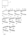
- An example for the method steps of the proposed method, some of which being optional steps, is shown in connection with figure 1 .
- the figure shows the manufacturing process of a mirror shell in a cross sectional view.
- Starting point is a block 1 of material with a size that is sufficient for machining the body of the shell.
- the material is selected to have material properties that fit to the application in a collector shell, for example for EUV applications.
- rough production steps like milling the block 1 of material are carried out to form the body 2 of the mirror shell as schematically indicated in figures 1a and 1b .
- An appropriate material is e.g. aluminum.
- cooling channels 3 are milled into the side faces of the mirror body 2 to form the cooling structure as schematically shown in figure 1c .
- the cooling structure is sealed e. g. by welding or brazing in figure 1d.
- Figure 1e shows the attachment of mounting jigs 4 which may be fixed by welding or screwing. These mounting jigs 4 are necessary for the mounting and connecting the shells to the mounting structure of the nested shells grazing incidence mirror.
- a functional test of these components e.g. a leak test of the cooling structure or a test of the stiffness of the mirror body may be applied.
- the optical surface of the shell is machined.
- the thickness of the mirror body in the direction perpendicular to the optical surface may be chosen slightly larger than needed.
- all of these steps include a diamond turning process for finishing of the optical surface.
- Figures 1f to 1j show these different steps some of which are only optional steps.
- the diamond turning process can be directly applied to generate the optical surface which is shown with the diamond turning finishing process 6 in figure 1h . Nevertheless there might be the necessity of more than one turning run. The optical surface 7 will then not be disturbed by other rough manufacturing processes.
- material from the inner surface of the mirror body may be turned away in the diamond turning pre-machining step 5 of figure 1f so that the desired surface is slightly outside the blank material.
- a layer 8 of a material which supports the required surface quality is coated on the blank inner surface as schematically indicated in figure 1g .
- This material may be a nickel rich material like nickel-phosphor.
- the desired surface is now within the layer 8 of the coating material.
- the optical surface is then generated by one or more diamond turning runs with the diamond turning finishing process 6 of figure 1h .
- the surface roughness of the optical surface can further be reduced by a conventional polishing step 9 (optional) schematically indicated in figure 1j .
- a coating of one or more layers 10 may be applied to increase the reflectivity and/or the mechanical or chemical stability, if necessary.
- This optional step is schematically indicated in figure 1j in which, for example, a layer of ruthenium may be applied as a reflective coating.
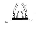
- FIG. 1 schematically shows a cross sectional view of such a nested shells grazing incidence mirror. In this figure only two shells 11 are shown. It is obvious for the skilled person that such a nested shells grazing incidence mirror may have more than two shells 11 concentrically arranged around the optical axis.
- the assembly of the shell modules is easier because a wider choice of e.g. welding and clamping techniques is possible for manufacturing the mechanical structures, since these techniques do not affect the optical surface of the shells.
- the proposed method also allows manufacturing of shells with non monotone optical surfaces by diamond turning.
- further mechanical structures may be integrated in or attached to the mechanical shells without deteriorating the optical quality due to the order of the proposed method steps, i.e. the generation of the optical surface in the final step.
- EUV light sources do not only emit photons but also produce undesired material, so called debris, such as droplets or atoms.
- the debris may condense on the optical components whose performance would deteriorate appropriately.
- the mirror body 2 of the mirror shells 11 is preferably formed to have a varying thickness increasing from both edges and forming one or several thicker portions in between.
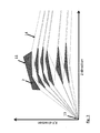
- Fig. 3 shows a schematic cross sectional view of a part of such a nested shells grazing incidence mirror.
- Both edges of the mirror bodies 2 of the inner shells are formed knife edge shaped while still having at least one portion with several centimeters thickness in between without blocking incoming EUV-radiation.
- the number, position and shape of these thicker portions is selected to avoid the blocking of the radiation.
Landscapes
- Physics & Mathematics (AREA)
- Engineering & Computer Science (AREA)
- General Physics & Mathematics (AREA)
- Epidemiology (AREA)
- Public Health (AREA)
- Health & Medical Sciences (AREA)
- Environmental & Geological Engineering (AREA)
- Spectroscopy & Molecular Physics (AREA)
- General Engineering & Computer Science (AREA)
- High Energy & Nuclear Physics (AREA)
- Mechanical Engineering (AREA)
- Optical Elements Other Than Lenses (AREA)
- Exposure And Positioning Against Photoresist Photosensitive Materials (AREA)
- Exposure Of Semiconductors, Excluding Electron Or Ion Beam Exposure (AREA)
Abstract
Description
- The present invention relates to a method of manufacturing mirror shells of a nested shells grazing incidence mirror, in particular for extreme ultraviolet radiation (EUV) and/or x-rays. Such a nested shells grazing incidence mirror comprises several mirror shells which are typically arranged concentrically around an optical axis along which the incidence radiation enters the mirror.
- Nested shells grazing incidence mirrors are used in x-ray, soft x-ray and EUV applications, e.g. in space-based x-ray telescopes or as collector mirrors or collector optics in EUV applications like EUV lithography.
- Grazing incidence mirrors make use of the physical effect of total reflection of radiation impinging on the surface of a medium under a small angle of incidence. This allows a rather simple realization of mirrors for x-rays or EUV radiation without the need of a high precision multi layer coatings as is the case for near normal incidence mirrors. In contrast to near normal incidence mirrors, the mirror shells of a nested shells grazing incidence mirror have a comparatively small thickness in the direction perpendicular to the reflecting surface in order to minimize the loss of the incoming radiation which also impinges on the side edges of the shells.
- The small thickness and the required high optical quality of the optical surface of such a mirror shell require a careful manufacturing process. Document
EP 2083328 A1 discloses two manners of manufacturing such mirror shells. - In one of the methods proposed in
EP 2083328 A1 the shells are manufactured by electroforming in which the shell material is galvanically deposited on a mandrel, which carries the negative of the required optical surface with respect to shape and roughness. After thermal break of shell and mandrel, a reflective coating can be applied to the optical surface of the shell if required. The mandrel can be reused for further replications unless it is destroyed during the separation process. The individual shells are then mounted to a mechanical support structure, typically some kind of spider wheel, to form the nested shells grazing incidence mirror. The manufacturing of the mirror shells by galvanic deposition however has a number of disadvantages. The bulk material of the shell must be compatible with the electroforming process. This limits the material choice to a couple of pure metals with only very few exceptions. Consequently, there are restrictions with respect to the material properties desired for the application. The dedicated galvanic deposition of the material is slow and without further measures does not allow a variation in thickness of the shell. Furthermore, the manufactured shells are very fragile and do not allow a refurbishment of the optical surface after degradation which occurs during operation of the mirror, e.g. close to an EUV source. The galvanic deposition furthermore has a significant impact on the costs of the grazing incidence mirror. Due to the fragility of the mirror shells it is also difficult to attach further mechanical structures which are required for mounting the mirror or during operation of the mirror, e.g. cooling structures. There is a high risk of damaging the surface during such later manufacturing steps, in particular when techniques like welding, drilling or milling are necessary. - Another method of manufacturing the mirror shells is only very shortly mentioned in
EP 2083328 A1 . This further method comprises to manufacture the mirror shells by diamond turning in order to achieve shells with a thickness of between 0.5 and 4 mm. The document does not further describe this manufacturing process. Further required mechanical structures for a thermal management system are mounted on the mirror shells, e.g. by micro-machining the rear surface of the mirror shells. Nevertheless, the thickness of the shells mentioned in this document also results in a high fragility so that several of the above mentioned disadvantages still apply. - Diamond turning is a well established technique for the manufacturing of reflective optical elements.
US 6,634,760 describes an ultra-precision diamond turning technique in which the mechanical process is combined with the deposition of a smoothing layer in order to achieve an optical surface with a high optical quality. - It is an object of the present invention to provide a method of manufacturing mirror shells of a nested shells grazing incidence mirror at low costs with high optical quality which may also be refurbished one or several times.
- The object is achieved with the method of manufacturing the mirror shells according to
claim 1. Advantageous embodiments of the method are subject matter of the dependent claims or can be deduced from the subsequent portions of the description of the invention and embodiments. - The proposed method comprises the steps of providing and machining a blank of a bulk material to form a mirror body of the shell. During or after the machining of the blank mechanical structures are integrated and/or attached in and/or to the mirror body. These mechanical structures may be required for mounting and/or operating the mirror shells. Examples of such mechanical structures are cooling channels which are required for cooling the mirror shells during operation. Such mechanical structures may also be mounting elements for mounting the mirror shells to a corresponding mechanical support structure which is required to assemble the nested shells grazing incidence mirror. These steps of integrating the mechanical structures or attaching these structures - or both measures in combination - may be performed during the machining of the blank, e.g. by forming appropriate grooves for the cooling channels, or immediately after forming the mirror body. The structures can also be attached for example by appropriate techniques like welding, brazing or screwing. After the integration and/or attachment of the mechanical structures the optical surface is formed on the mirror body by diamond turning. Depending on the material selected for the mirror body the diamond turning may be performed directly on the surface of the mirror body or may also be performed on a coated layer of an appropriate material which may be applied prior to this last step of diamond turning to the corresponding regions of the surface of the body.
- Since the manufacturing steps for forming the mirror body and integrating and/or attaching all required further mechanical structures are performed prior to the manufacturing step of diamond turning the optical surface, the risk of a deformation or damaging of the optical surface due to rough process steps is avoided. By this, usual manufacturing techniques like brazing, welding, drilling, milling and turning are possible to generate the required mechanical structures for cooling and mounting. Since the optical surface is formed in the latest step, which may also include a further polishing or coating, the imaging quality of the optical system is better than with other techniques in which the mechanical structures are applied after the formation of the optical surface. The proposed method of machining the mirror body from a blank, e.g. by milling, and forming the optical surface by diamond turning allows the selection of a large amount of shell materials. The material of the mirror body can thus be selected to optimally support the needs of the application, e.g. thermo-mechanically and/or chemically. The manufacturing process does not result in any restrictions for the shell thickness and therefore also strong variations of the thickness within a shell are possible, if desired. The mirror body may be formed of an appropriate thickness to allow a refurbishment of the optical surface by a second or further diamond turning run in cases in which the surface is degraded after a certain operation time. In case of the diamond turning being carried out in a coating on the mirror body, also a second diamond turning run is possible in the coating. Alternatively the coating (or its rest) is first removed and a new coating is applied. The diamond turning finishing process is then repeated with this new coating. The coating can be removed for example by another diamond turning step or by chemical treatment. Using such a refurbishment costly manufacturing steps on the blank like forming of the complex cooling structures can be avoided since the mirror shell is simply recycled.
- In an advantageous embodiment the mirror body is formed to have a varying thickness, the thickness being measured perpendicular to the optical surface. This thickness is smallest at the edges and increases from both edges to provide one or several thicker portions in between. The number, position, shape and maximum thickness of these thicker portions is selected to avoid a blocking of the incoming radiation by the thicker portions when the shells are mounted in the nested shells grazing incidence mirror. With such a design of the mirror body the thicker portions can have up to several centimeters in thickness without blocking the incoming radiation, in particular if the mirror body is formed to have knife edge shaped edges.
- Preferably the mirror body is manufactured with a thickness of ≥ 5 mm at the thickness maximum of at least one of the thicker portions. With such a thickness, the problems related to a fragility of the shells are substantially reduced resulting in a lower risk of damage during manufacturing and/or later refurbishment.
- In the proposed method it is also possible to additionally polish the optical surface after the diamond turning process. Furthermore, also one or several additional coatings may be applied to the optical surface, e.g. a coating for increasing the reflectivity of the surface or a coating for increasing the mechanical and/or chemical stability of the surface.
- The proposed method is described in the following by way of example in connection with the accompanying figures which show:
- Fig. 1
- an example of manufacturing steps of the proposed method;
- Fig. 2
- a schematic view of a nested shells grazing incidence mirror; and
- Fig. 3
- a schematic cross sectional view of a part of a nested shells grazing incidence mirror having mirror shells with varying thickness.
- In the proposed method of manufacturing mirror shells of a nested shells grazing incidence mirror, first the body of the mirror is made, including e.g. the cooling channels and the fixation points for later mounting. After the body is completely finished, the optical surface is generated by an ultra-precision diamond turning process. For diamond turning, the process described in
US 6,634,760 may be used for example. With the process flow of the proposed method it is also possible to refurbish the shells as explained further on. An example for the method steps of the proposed method, some of which being optional steps, is shown in connection withfigure 1 . The figure shows the manufacturing process of a mirror shell in a cross sectional view. - Starting point is a
block 1 of material with a size that is sufficient for machining the body of the shell. The material is selected to have material properties that fit to the application in a collector shell, for example for EUV applications. First of all, rough production steps like milling theblock 1 of material are carried out to form thebody 2 of the mirror shell as schematically indicated infigures 1a and 1b . An appropriate material is e.g. aluminum. - After the formation of the mirror
body cooling channels 3 are milled into the side faces of themirror body 2 to form the cooling structure as schematically shown infigure 1c . The cooling structure is sealed e. g. by welding or brazing infigure 1d. Figure 1e shows the attachment of mountingjigs 4 which may be fixed by welding or screwing. These mountingjigs 4 are necessary for the mounting and connecting the shells to the mounting structure of the nested shells grazing incidence mirror. After these rough manufacturing steps a functional test of these components, e.g. a leak test of the cooling structure or a test of the stiffness of the mirror body may be applied. - After the manufacturing of all of the necessary mechanical components or structures the optical surface of the shell is machined. To this end the thickness of the mirror body in the direction perpendicular to the optical surface may be chosen slightly larger than needed. For forming the optical surface different combinations of manufacturing steps may be applied, all of these steps include a diamond turning process for finishing of the optical surface.
Figures 1f to 1j show these different steps some of which are only optional steps. - If the chosen blank material allows the surface finishing of the desired quality, the diamond turning process can be directly applied to generate the optical surface which is shown with the diamond
turning finishing process 6 infigure 1h . Nevertheless there might be the necessity of more than one turning run. Theoptical surface 7 will then not be disturbed by other rough manufacturing processes. - If the blank material does not support the required surface quality directly, material from the inner surface of the mirror body may be turned away in the diamond turning
pre-machining step 5 offigure 1f so that the desired surface is slightly outside the blank material. Now alayer 8 of a material which supports the required surface quality is coated on the blank inner surface as schematically indicated infigure 1g . This material may be a nickel rich material like nickel-phosphor. The desired surface is now within thelayer 8 of the coating material. The optical surface is then generated by one or more diamond turning runs with the diamondturning finishing process 6 offigure 1h . - If required, the surface roughness of the optical surface can further be reduced by a conventional polishing step 9 (optional) schematically indicated in
figure 1j . Also a coating of one ormore layers 10 may be applied to increase the reflectivity and/or the mechanical or chemical stability, if necessary. This optional step is schematically indicated infigure 1j in which, for example, a layer of ruthenium may be applied as a reflective coating. - After having manufactured the
different mirror shells 11 required for assembling the nested shells grazing incidence mirror, theshells 11 are mounted to amechanical support structure 12, e.g. some kind of spider wheel as known from existing grazing incidence collectors, to form the nested shells mirror.Figure 2 schematically shows a cross sectional view of such a nested shells grazing incidence mirror. In this figure only twoshells 11 are shown. It is obvious for the skilled person that such a nested shells grazing incidence mirror may have more than twoshells 11 concentrically arranged around the optical axis. - With the proposed order of manufacturing steps the assembly of the shell modules is easier because a wider choice of e.g. welding and clamping techniques is possible for manufacturing the mechanical structures, since these techniques do not affect the optical surface of the shells. The proposed method also allows manufacturing of shells with non monotone optical surfaces by diamond turning.
- Additionally, further mechanical structures may be integrated in or attached to the mechanical shells without deteriorating the optical quality due to the order of the proposed method steps, i.e. the generation of the optical surface in the final step. For example, EUV light sources do not only emit photons but also produce undesired material, so called debris, such as droplets or atoms. The debris may condense on the optical components whose performance would deteriorate appropriately. It is known in the art to apply debris mitigation systems by assistance of certain inert gases to reduce this negative impact on system performance. Due to the flexibility and robustness of the diamond turning process, it is possible to realized dedicated layouts of shells resulting in an improved debris mitigation performance of the optical system. This can be achieved by e.g. drilling additional holes or add gas line tubing at certain locations, in particular locations which are shadowed by the mechanical support structure of the shells, to allow for a particular gas distribution which enhances debris mitigation performance. This is impossible with a conventional manufactured nested shell optic but can be integrated in the proposed manufacturing process easily. The proposed manufacturing method allows to realize a grazing incidence collector that is much cheaper to produce, more robust and can be refurbished several times.
- The
mirror body 2 of themirror shells 11 is preferably formed to have a varying thickness increasing from both edges and forming one or several thicker portions in between.Fig. 3 shows a schematic cross sectional view of a part of such a nested shells grazing incidence mirror. - Both edges of the
mirror bodies 2 of the inner shells are formed knife edge shaped while still having at least one portion with several centimeters thickness in between without blocking incoming EUV-radiation. The number, position and shape of these thicker portions is selected to avoid the blocking of the radiation. This can be seen fromFig. 3 in which some of the incoming EUV-rays 14 originating from the EUV-source 13 are indicated. With the proposed method it is thus possible to design and manufacture an almost obscuration free collector consisting of very robust (=thick) mirror shells. - While the invention has been illustrated and described in detail in the drawings and forgoing description, such illustration and description are to be considered illustrative or exemplary and not restrictive; the invention is not limited to the disclosed embodiments. For example, although the figures show a special curved shape of the mirror shells also other shapes are possible. The mechanical structures manufactured prior to the final diamond turning step may also be different from the structures shown in the figures. Other variations of the disclosed embodiments can be understood and affected by those skilled in the art in practicing the claimed invention, from a study of the drawings, the disclosure, and the appended claims. In the claims the word "comprising" does not exclude other elements or steps and the indefinite article "a" or "an" does not exclude a plurality. The mere fact that certain measures are recited in mutually different dependent claims does not indicate that a combination of these measures can not be used to advantage. The reference signs in the claims should not be construed as limiting the scope.
-
- 1
- block of material (blank)
- 2
- mirror body
- 3
- cooling channels
- 4
- mounting jigs
- 5
- diamond turning pre-machining step
- 6
- diamond turning finishing process
- 7
- optical surface
- 8
- layer of material
- 9
- polishing
- 10
- coating
- 11
- mirror shell
- 12
- support structure
- 13
- EUV-source
- 14
- EUV-ray
Claims (10)
- A method of manufacturing mirror shells (11) of a nested shells grazing incidence mirror, in particular for EUV radiation and/or X-rays, the method at least comprising the steps of- providing and machining a blank (1) of a bulk material to form a mirror body (2) of the shell (11),- integrating and/or attaching mechanical structures (3, 4) in and/or to the mirror body (2) during and/or after said step of machining the blank (1), and- forming an optical surface (7) on the mirror body (2) including said mechanical structures (3, 4) by diamond turning.
- The method according to claim 1,
wherein said step of forming the optical surface (7) includes the steps of- coating the mirror body (2) at least in a region in which said optical surface is formed with a layer (8) of a second material, said second material being selected to allow the formation of the optical surface from said second material by diamond turning, and- diamond turning said layer (8) of the second material. - The method according to claim 1 or 2,
wherein said step of integrating and/or attaching mechanical structures (3, 4) includes integrating and/or attaching cooling channels (3) and/or mounting elements (4) in and/or to the mirror body (2). - The method according to one of claims 1 to 3,
wherein said machining of the blank (1) to form the mirror body (2) comprises at least a milling process. - The method according to one of claims 1 to 4,
wherein said attaching of mechanical structures (3, 4) to the mirror body (2) comprises at least one of welding and brazing and screwing said structures (3, 4) to the mirror body (2). - The method according to one of claims 1 to 5,
wherein said mirror body (2) is formed to have a thickness increasing from both edges of the mirror body (2) to form at least one thicker portion in between. - The method according to claim 6,
wherein said mirror body (2) is formed to have edges which are knife edge shaped. - The method according to claim 6 or 7,
wherein said mirror body (2) is formed to have a thickness of ≥ 5 mm at a thickness maximum of said at least one thicker portion. - The method according to one of claims 1 to 8,
wherein the optical surface (7) is additionally polished. - The method according to one of claims 1 to 9,
wherein the optical surface (7) is additionally coated by an appropriate material increasing the reflectivity and/or the mechanical and/or chemical stability of the optical surface (7).
Priority Applications (3)
| Application Number | Priority Date | Filing Date | Title |
|---|---|---|---|
| EP12008518.8A EP2746850B1 (en) | 2012-12-20 | 2012-12-20 | Method of manufacturing mirror shells of a nested shells grazing incidence mirror |
| JP2013255815A JP2014123726A (en) | 2012-12-20 | 2013-12-11 | Method of manufacturing mirror shell of nested shell grazing incidence mirror |
| US14/107,118 US9421647B2 (en) | 2012-12-20 | 2013-12-16 | Method of manufacturing mirror shells of a nested shells grazing incidence mirror |
Applications Claiming Priority (1)
| Application Number | Priority Date | Filing Date | Title |
|---|---|---|---|
| EP12008518.8A EP2746850B1 (en) | 2012-12-20 | 2012-12-20 | Method of manufacturing mirror shells of a nested shells grazing incidence mirror |
Publications (2)
| Publication Number | Publication Date |
|---|---|
| EP2746850A1 true EP2746850A1 (en) | 2014-06-25 |
| EP2746850B1 EP2746850B1 (en) | 2015-03-18 |
Family
ID=47602739
Family Applications (1)
| Application Number | Title | Priority Date | Filing Date |
|---|---|---|---|
| EP12008518.8A Not-in-force EP2746850B1 (en) | 2012-12-20 | 2012-12-20 | Method of manufacturing mirror shells of a nested shells grazing incidence mirror |
Country Status (3)
| Country | Link |
|---|---|
| US (1) | US9421647B2 (en) |
| EP (1) | EP2746850B1 (en) |
| JP (1) | JP2014123726A (en) |
Cited By (1)
| Publication number | Priority date | Publication date | Assignee | Title |
|---|---|---|---|---|
| IT202000017086A1 (en) * | 2020-07-14 | 2022-01-14 | Istituto Naz Di Astrofisica | PROCEDURE FOR THE REALIZATION OF OPTICAL ELEMENTS FOR OPTICS OF TELESCOPES USABLE IN SPACE MISSIONS |
Families Citing this family (1)
| Publication number | Priority date | Publication date | Assignee | Title |
|---|---|---|---|---|
| US20160097885A1 (en) * | 2014-10-03 | 2016-04-07 | Corning Incorporated | Mirror substrates with highly finishable corrosion-resistant coating |
Citations (3)
| Publication number | Priority date | Publication date | Assignee | Title |
|---|---|---|---|---|
| US5768339A (en) * | 1995-10-13 | 1998-06-16 | O'hara; David B. | Collimator for x-ray spectroscopy |
| US20030043483A1 (en) * | 2001-08-27 | 2003-03-06 | The Regents Of The University Of California | Low-cost method for producing extreme ultraviolet lithography optics |
| EP2083328A1 (en) | 2008-01-28 | 2009-07-29 | Media Lario S.r.L. | Grazing incidence collector for laser produced plasma sources |
Family Cites Families (2)
| Publication number | Priority date | Publication date | Assignee | Title |
|---|---|---|---|---|
| WO2013001714A1 (en) * | 2011-06-30 | 2013-01-03 | キヤノンアネルバ株式会社 | Film-forming device |
| WO2013017144A1 (en) * | 2011-08-01 | 2013-02-07 | Fraunhofer-Gesellschaft Zur Förderung Der Angewandten Forschung E.V. . | Method for manufacturing a mirror comprising at least one cavity and optical mirror |
-
2012
- 2012-12-20 EP EP12008518.8A patent/EP2746850B1/en not_active Not-in-force
-
2013
- 2013-12-11 JP JP2013255815A patent/JP2014123726A/en active Pending
- 2013-12-16 US US14/107,118 patent/US9421647B2/en not_active Expired - Fee Related
Patent Citations (4)
| Publication number | Priority date | Publication date | Assignee | Title |
|---|---|---|---|---|
| US5768339A (en) * | 1995-10-13 | 1998-06-16 | O'hara; David B. | Collimator for x-ray spectroscopy |
| US20030043483A1 (en) * | 2001-08-27 | 2003-03-06 | The Regents Of The University Of California | Low-cost method for producing extreme ultraviolet lithography optics |
| US6634760B2 (en) | 2001-08-27 | 2003-10-21 | The Regents Of The University Of California | Low-cost method for producing extreme ultraviolet lithography optics |
| EP2083328A1 (en) | 2008-01-28 | 2009-07-29 | Media Lario S.r.L. | Grazing incidence collector for laser produced plasma sources |
Non-Patent Citations (4)
| Title |
|---|
| BEAUCAMP A T H ET AL: "Automated finishing of diamond turned dies for hard X-ray and EUV optics replication", PROCEEDINGS OF SPIE - THE INTERNATIONAL SOCIETY FOR OPTICAL ENGINEERING - ADVANCES IN X-RAY/EUV OPTICS AND COMPONENTS VII 2012 SPIE USA, vol. 8502, 15 October 2012 (2012-10-15), XP002711564, DOI: 10.1117/12.929632 * |
| CHON K S ET AL: "Precision machining of electroless nickel mandrel and fabrication of replicated mirrors for a soft X-ray microscope", JSME INTERNATIONAL JOURNAL, SERIES C: MECHANICAL SYSTEMS, MACHINE ELEMENTS AND MANUFACTURING 20060915 JAPAN SOCIETY OF MECHANICAL ENGINEERS JP, vol. 49, no. 1, 15 September 2006 (2006-09-15), pages 56 - 62, XP002711565, DOI: 10.1299/JSMEC.49.56 * |
| EGLE W ET AL: "EUV COLLECTORS: DESIGN, DEVELOPMENT, FABRICATION AND TESTING", PROCEEDINGS OF SPIE, SPIE, US, vol. 5193, 1 January 2004 (2004-01-01), pages 39 - 49, XP002348559, ISSN: 0277-786X, DOI: 10.1117/12.507736 * |
| FAWCETT STEVEN C ET AL: "Development of Wolter I x-ray optics by diamond turning and electrochemical replication", PRECISION ENGINEERING 1995 OCT BUTTERWORTH-HEINEMANN LTD, vol. 17, no. 4, October 1995 (1995-10-01), pages 290 - 297, XP002711566, DOI: 10.1016/0141-6359(95)00018-9 * |
Cited By (3)
| Publication number | Priority date | Publication date | Assignee | Title |
|---|---|---|---|---|
| IT202000017086A1 (en) * | 2020-07-14 | 2022-01-14 | Istituto Naz Di Astrofisica | PROCEDURE FOR THE REALIZATION OF OPTICAL ELEMENTS FOR OPTICS OF TELESCOPES USABLE IN SPACE MISSIONS |
| WO2022013768A1 (en) * | 2020-07-14 | 2022-01-20 | Istituto Nazionale Di Astrofisica | Process for manufacturing optical elements for telescope optics usable in space missions |
| US11945017B2 (en) | 2020-07-14 | 2024-04-02 | Istituto Nazionale Di Astrofisica | Process for manufacturing optical elements for telescope optics usable in space missions |
Also Published As
| Publication number | Publication date |
|---|---|
| EP2746850B1 (en) | 2015-03-18 |
| US9421647B2 (en) | 2016-08-23 |
| US20140173875A1 (en) | 2014-06-26 |
| JP2014123726A (en) | 2014-07-03 |
Similar Documents
| Publication | Publication Date | Title |
|---|---|---|
| JP7777194B2 (en) | Pellicle and pellicle assembly | |
| EP2686133B1 (en) | Method for producing a reflective optical component for an euv projection exposure apparatus and component of this type | |
| US10534269B2 (en) | Method for producing a reflective optical element, reflective optical element, and use of a reflective optical element | |
| EP2083328A1 (en) | Grazing incidence collector for laser produced plasma sources | |
| EP3257054B1 (en) | Euv multilayer mirror, optical system including a multilayer mirror and method of manufacturing a multilayer mirror | |
| US9459538B2 (en) | Lithography apparatus and method for producing a mirror arrangement | |
| US9791662B2 (en) | Lightweight carrier structure, particularly for optical components, and method for its production | |
| WO2007051638A1 (en) | Optical component, inparticular collector for use in euv lithography | |
| US20190285989A1 (en) | Intensity adaptation filter for euv microlithography, method for producing same, and illumination system having a corresponding filter | |
| Zhang et al. | High resolution and high throughput x-ray optics for future astronomical missions | |
| JP2019207426A (en) | UV protective coating for lens assembly | |
| EP2746850B1 (en) | Method of manufacturing mirror shells of a nested shells grazing incidence mirror | |
| US20170261867A1 (en) | Optical assembly having a thermally conductive component | |
| US8795839B2 (en) | Repair method for optical elements having a coating and corresponding optical elements | |
| TW201923483A (en) | Assembly for use in semiconductor photolithography and method of manufacturing same | |
| CA3129112A1 (en) | Process for manufacturing an athermal low cost telescope based on high precision replication technology, and such telescope | |
| US11945017B2 (en) | Process for manufacturing optical elements for telescope optics usable in space missions | |
| EP1152555A1 (en) | Telescope mirror for high bandwidth free space optical data transmission | |
| US7347572B1 (en) | Telescope mirror for high bandwidth free space optical data transmission | |
| US20220111439A1 (en) | Three-dimensional printing of optical mirror | |
| CN120249883A (en) | Micro-nano structure reflector processing method, system and micro-nano structure reflector | |
| Leblanc et al. | Large active mirror in aluminium | |
| Kilaru et al. | X-Ray Optics Development at MSFC | |
| KR20070108677A (en) | X-ray exposure method |
Legal Events
| Date | Code | Title | Description |
|---|---|---|---|
| PUAI | Public reference made under article 153(3) epc to a published international application that has entered the european phase |
Free format text: ORIGINAL CODE: 0009012 |
|
| 17P | Request for examination filed |
Effective date: 20131114 |
|
| AK | Designated contracting states |
Kind code of ref document: A1 Designated state(s): AL AT BE BG CH CY CZ DE DK EE ES FI FR GB GR HR HU IE IS IT LI LT LU LV MC MK MT NL NO PL PT RO RS SE SI SK SM TR |
|
| AX | Request for extension of the european patent |
Extension state: BA ME |
|
| GRAP | Despatch of communication of intention to grant a patent |
Free format text: ORIGINAL CODE: EPIDOSNIGR1 |
|
| INTG | Intention to grant announced |
Effective date: 20140822 |
|
| GRAS | Grant fee paid |
Free format text: ORIGINAL CODE: EPIDOSNIGR3 |
|
| GRAA | (expected) grant |
Free format text: ORIGINAL CODE: 0009210 |
|
| AK | Designated contracting states |
Kind code of ref document: B1 Designated state(s): AL AT BE BG CH CY CZ DE DK EE ES FI FR GB GR HR HU IE IS IT LI LT LU LV MC MK MT NL NO PL PT RO RS SE SI SK SM TR |
|
| REG | Reference to a national code |
Ref country code: GB Ref legal event code: FG4D |
|
| REG | Reference to a national code |
Ref country code: CH Ref legal event code: EP |
|
| REG | Reference to a national code |
Ref country code: IE Ref legal event code: FG4D |
|
| REG | Reference to a national code |
Ref country code: AT Ref legal event code: REF Ref document number: 716937 Country of ref document: AT Kind code of ref document: T Effective date: 20150415 |
|
| REG | Reference to a national code |
Ref country code: DE Ref legal event code: R096 Ref document number: 602012005899 Country of ref document: DE Effective date: 20150430 |
|
| REG | Reference to a national code |
Ref country code: NL Ref legal event code: T3 |
|
| PG25 | Lapsed in a contracting state [announced via postgrant information from national office to epo] |
Ref country code: FI Free format text: LAPSE BECAUSE OF FAILURE TO SUBMIT A TRANSLATION OF THE DESCRIPTION OR TO PAY THE FEE WITHIN THE PRESCRIBED TIME-LIMIT Effective date: 20150318 Ref country code: HR Free format text: LAPSE BECAUSE OF FAILURE TO SUBMIT A TRANSLATION OF THE DESCRIPTION OR TO PAY THE FEE WITHIN THE PRESCRIBED TIME-LIMIT Effective date: 20150318 Ref country code: SE Free format text: LAPSE BECAUSE OF FAILURE TO SUBMIT A TRANSLATION OF THE DESCRIPTION OR TO PAY THE FEE WITHIN THE PRESCRIBED TIME-LIMIT Effective date: 20150318 Ref country code: NO Free format text: LAPSE BECAUSE OF FAILURE TO SUBMIT A TRANSLATION OF THE DESCRIPTION OR TO PAY THE FEE WITHIN THE PRESCRIBED TIME-LIMIT Effective date: 20150618 Ref country code: LT Free format text: LAPSE BECAUSE OF FAILURE TO SUBMIT A TRANSLATION OF THE DESCRIPTION OR TO PAY THE FEE WITHIN THE PRESCRIBED TIME-LIMIT Effective date: 20150318 |
|
| REG | Reference to a national code |
Ref country code: AT Ref legal event code: MK05 Ref document number: 716937 Country of ref document: AT Kind code of ref document: T Effective date: 20150318 |
|
| REG | Reference to a national code |
Ref country code: LT Ref legal event code: MG4D |
|
| PG25 | Lapsed in a contracting state [announced via postgrant information from national office to epo] |
Ref country code: GR Free format text: LAPSE BECAUSE OF FAILURE TO SUBMIT A TRANSLATION OF THE DESCRIPTION OR TO PAY THE FEE WITHIN THE PRESCRIBED TIME-LIMIT Effective date: 20150619 Ref country code: RS Free format text: LAPSE BECAUSE OF FAILURE TO SUBMIT A TRANSLATION OF THE DESCRIPTION OR TO PAY THE FEE WITHIN THE PRESCRIBED TIME-LIMIT Effective date: 20150318 Ref country code: LV Free format text: LAPSE BECAUSE OF FAILURE TO SUBMIT A TRANSLATION OF THE DESCRIPTION OR TO PAY THE FEE WITHIN THE PRESCRIBED TIME-LIMIT Effective date: 20150318 |
|
| PG25 | Lapsed in a contracting state [announced via postgrant information from national office to epo] |
Ref country code: CZ Free format text: LAPSE BECAUSE OF FAILURE TO SUBMIT A TRANSLATION OF THE DESCRIPTION OR TO PAY THE FEE WITHIN THE PRESCRIBED TIME-LIMIT Effective date: 20150318 Ref country code: PT Free format text: LAPSE BECAUSE OF FAILURE TO SUBMIT A TRANSLATION OF THE DESCRIPTION OR TO PAY THE FEE WITHIN THE PRESCRIBED TIME-LIMIT Effective date: 20150720 Ref country code: ES Free format text: LAPSE BECAUSE OF FAILURE TO SUBMIT A TRANSLATION OF THE DESCRIPTION OR TO PAY THE FEE WITHIN THE PRESCRIBED TIME-LIMIT Effective date: 20150318 Ref country code: SK Free format text: LAPSE BECAUSE OF FAILURE TO SUBMIT A TRANSLATION OF THE DESCRIPTION OR TO PAY THE FEE WITHIN THE PRESCRIBED TIME-LIMIT Effective date: 20150318 Ref country code: EE Free format text: LAPSE BECAUSE OF FAILURE TO SUBMIT A TRANSLATION OF THE DESCRIPTION OR TO PAY THE FEE WITHIN THE PRESCRIBED TIME-LIMIT Effective date: 20150318 Ref country code: RO Free format text: LAPSE BECAUSE OF FAILURE TO SUBMIT A TRANSLATION OF THE DESCRIPTION OR TO PAY THE FEE WITHIN THE PRESCRIBED TIME-LIMIT Effective date: 20150318 |
|
| PG25 | Lapsed in a contracting state [announced via postgrant information from national office to epo] |
Ref country code: AT Free format text: LAPSE BECAUSE OF FAILURE TO SUBMIT A TRANSLATION OF THE DESCRIPTION OR TO PAY THE FEE WITHIN THE PRESCRIBED TIME-LIMIT Effective date: 20150318 Ref country code: PL Free format text: LAPSE BECAUSE OF FAILURE TO SUBMIT A TRANSLATION OF THE DESCRIPTION OR TO PAY THE FEE WITHIN THE PRESCRIBED TIME-LIMIT Effective date: 20150318 Ref country code: IS Free format text: LAPSE BECAUSE OF FAILURE TO SUBMIT A TRANSLATION OF THE DESCRIPTION OR TO PAY THE FEE WITHIN THE PRESCRIBED TIME-LIMIT Effective date: 20150718 |
|
| REG | Reference to a national code |
Ref country code: DE Ref legal event code: R097 Ref document number: 602012005899 Country of ref document: DE |
|
| PG25 | Lapsed in a contracting state [announced via postgrant information from national office to epo] |
Ref country code: IT Free format text: LAPSE BECAUSE OF FAILURE TO SUBMIT A TRANSLATION OF THE DESCRIPTION OR TO PAY THE FEE WITHIN THE PRESCRIBED TIME-LIMIT Effective date: 20150318 |
|
| PLBE | No opposition filed within time limit |
Free format text: ORIGINAL CODE: 0009261 |
|
| STAA | Information on the status of an ep patent application or granted ep patent |
Free format text: STATUS: NO OPPOSITION FILED WITHIN TIME LIMIT |
|
| PG25 | Lapsed in a contracting state [announced via postgrant information from national office to epo] |
Ref country code: DK Free format text: LAPSE BECAUSE OF FAILURE TO SUBMIT A TRANSLATION OF THE DESCRIPTION OR TO PAY THE FEE WITHIN THE PRESCRIBED TIME-LIMIT Effective date: 20150318 |
|
| 26N | No opposition filed |
Effective date: 20151221 |
|
| PG25 | Lapsed in a contracting state [announced via postgrant information from national office to epo] |
Ref country code: SI Free format text: LAPSE BECAUSE OF FAILURE TO SUBMIT A TRANSLATION OF THE DESCRIPTION OR TO PAY THE FEE WITHIN THE PRESCRIBED TIME-LIMIT Effective date: 20150318 |
|
| PG25 | Lapsed in a contracting state [announced via postgrant information from national office to epo] |
Ref country code: BE Free format text: LAPSE BECAUSE OF NON-PAYMENT OF DUE FEES Effective date: 20151231 |
|
| PG25 | Lapsed in a contracting state [announced via postgrant information from national office to epo] |
Ref country code: MC Free format text: LAPSE BECAUSE OF FAILURE TO SUBMIT A TRANSLATION OF THE DESCRIPTION OR TO PAY THE FEE WITHIN THE PRESCRIBED TIME-LIMIT Effective date: 20150318 Ref country code: LU Free format text: LAPSE BECAUSE OF FAILURE TO SUBMIT A TRANSLATION OF THE DESCRIPTION OR TO PAY THE FEE WITHIN THE PRESCRIBED TIME-LIMIT Effective date: 20151220 |
|
| REG | Reference to a national code |
Ref country code: CH Ref legal event code: PL |
|
| PG25 | Lapsed in a contracting state [announced via postgrant information from national office to epo] |
Ref country code: BE Free format text: LAPSE BECAUSE OF FAILURE TO SUBMIT A TRANSLATION OF THE DESCRIPTION OR TO PAY THE FEE WITHIN THE PRESCRIBED TIME-LIMIT Effective date: 20150318 |
|
| REG | Reference to a national code |
Ref country code: IE Ref legal event code: MM4A |
|
| REG | Reference to a national code |
Ref country code: FR Ref legal event code: ST Effective date: 20160831 |
|
| PG25 | Lapsed in a contracting state [announced via postgrant information from national office to epo] |
Ref country code: CH Free format text: LAPSE BECAUSE OF NON-PAYMENT OF DUE FEES Effective date: 20151231 Ref country code: LI Free format text: LAPSE BECAUSE OF NON-PAYMENT OF DUE FEES Effective date: 20151231 Ref country code: IE Free format text: LAPSE BECAUSE OF NON-PAYMENT OF DUE FEES Effective date: 20151220 |
|
| PG25 | Lapsed in a contracting state [announced via postgrant information from national office to epo] |
Ref country code: FR Free format text: LAPSE BECAUSE OF NON-PAYMENT OF DUE FEES Effective date: 20151231 |
|
| PG25 | Lapsed in a contracting state [announced via postgrant information from national office to epo] |
Ref country code: SM Free format text: LAPSE BECAUSE OF FAILURE TO SUBMIT A TRANSLATION OF THE DESCRIPTION OR TO PAY THE FEE WITHIN THE PRESCRIBED TIME-LIMIT Effective date: 20150318 Ref country code: BG Free format text: LAPSE BECAUSE OF FAILURE TO SUBMIT A TRANSLATION OF THE DESCRIPTION OR TO PAY THE FEE WITHIN THE PRESCRIBED TIME-LIMIT Effective date: 20150318 Ref country code: HU Free format text: LAPSE BECAUSE OF FAILURE TO SUBMIT A TRANSLATION OF THE DESCRIPTION OR TO PAY THE FEE WITHIN THE PRESCRIBED TIME-LIMIT; INVALID AB INITIO Effective date: 20121220 |
|
| PG25 | Lapsed in a contracting state [announced via postgrant information from national office to epo] |
Ref country code: CY Free format text: LAPSE BECAUSE OF FAILURE TO SUBMIT A TRANSLATION OF THE DESCRIPTION OR TO PAY THE FEE WITHIN THE PRESCRIBED TIME-LIMIT Effective date: 20150318 |
|
| GBPC | Gb: european patent ceased through non-payment of renewal fee |
Effective date: 20161220 |
|
| PG25 | Lapsed in a contracting state [announced via postgrant information from national office to epo] |
Ref country code: MT Free format text: LAPSE BECAUSE OF FAILURE TO SUBMIT A TRANSLATION OF THE DESCRIPTION OR TO PAY THE FEE WITHIN THE PRESCRIBED TIME-LIMIT Effective date: 20150318 |
|
| PG25 | Lapsed in a contracting state [announced via postgrant information from national office to epo] |
Ref country code: GB Free format text: LAPSE BECAUSE OF NON-PAYMENT OF DUE FEES Effective date: 20161220 |
|
| PG25 | Lapsed in a contracting state [announced via postgrant information from national office to epo] |
Ref country code: MK Free format text: LAPSE BECAUSE OF FAILURE TO SUBMIT A TRANSLATION OF THE DESCRIPTION OR TO PAY THE FEE WITHIN THE PRESCRIBED TIME-LIMIT Effective date: 20150318 |
|
| PG25 | Lapsed in a contracting state [announced via postgrant information from national office to epo] |
Ref country code: TR Free format text: LAPSE BECAUSE OF FAILURE TO SUBMIT A TRANSLATION OF THE DESCRIPTION OR TO PAY THE FEE WITHIN THE PRESCRIBED TIME-LIMIT Effective date: 20150318 Ref country code: AL Free format text: LAPSE BECAUSE OF FAILURE TO SUBMIT A TRANSLATION OF THE DESCRIPTION OR TO PAY THE FEE WITHIN THE PRESCRIBED TIME-LIMIT Effective date: 20150318 |
|
| PGFP | Annual fee paid to national office [announced via postgrant information from national office to epo] |
Ref country code: NL Payment date: 20201113 Year of fee payment: 9 |
|
| PGFP | Annual fee paid to national office [announced via postgrant information from national office to epo] |
Ref country code: DE Payment date: 20201208 Year of fee payment: 9 |
|
| REG | Reference to a national code |
Ref country code: DE Ref legal event code: R119 Ref document number: 602012005899 Country of ref document: DE |
|
| REG | Reference to a national code |
Ref country code: NL Ref legal event code: MM Effective date: 20220101 |
|
| PG25 | Lapsed in a contracting state [announced via postgrant information from national office to epo] |
Ref country code: NL Free format text: LAPSE BECAUSE OF NON-PAYMENT OF DUE FEES Effective date: 20220101 |
|
| PG25 | Lapsed in a contracting state [announced via postgrant information from national office to epo] |
Ref country code: DE Free format text: LAPSE BECAUSE OF NON-PAYMENT OF DUE FEES Effective date: 20220701 |