EP2746816A1 - Gamma ray scintillation detector preserving the original scintillation light distribution - Google Patents
Gamma ray scintillation detector preserving the original scintillation light distribution Download PDFInfo
- Publication number
- EP2746816A1 EP2746816A1 EP12008547.7A EP12008547A EP2746816A1 EP 2746816 A1 EP2746816 A1 EP 2746816A1 EP 12008547 A EP12008547 A EP 12008547A EP 2746816 A1 EP2746816 A1 EP 2746816A1
- Authority
- EP
- European Patent Office
- Prior art keywords
- scintillator
- scintillation
- face
- photo sensor
- light
- Prior art date
- Legal status (The legal status is an assumption and is not a legal conclusion. Google has not performed a legal analysis and makes no representation as to the accuracy of the status listed.)
- Granted
Links
- 230000005251 gamma ray Effects 0.000 title description 35
- 230000003993 interaction Effects 0.000 claims abstract description 4
- 239000013078 crystal Substances 0.000 claims description 13
- 239000000463 material Substances 0.000 claims description 6
- 150000001875 compounds Chemical class 0.000 claims description 5
- XUIMIQQOPSSXEZ-UHFFFAOYSA-N Silicon Chemical compound [Si] XUIMIQQOPSSXEZ-UHFFFAOYSA-N 0.000 claims description 3
- 239000004033 plastic Substances 0.000 claims description 3
- 239000000919 ceramic Substances 0.000 claims description 2
- 239000011521 glass Substances 0.000 claims description 2
- 230000008901 benefit Effects 0.000 description 7
- 230000008878 coupling Effects 0.000 description 7
- 238000010168 coupling process Methods 0.000 description 7
- 238000005859 coupling reaction Methods 0.000 description 7
- 230000005855 radiation Effects 0.000 description 6
- 239000006185 dispersion Substances 0.000 description 5
- 230000003287 optical effect Effects 0.000 description 4
- 238000002600 positron emission tomography Methods 0.000 description 4
- 238000001514 detection method Methods 0.000 description 3
- 238000003745 diagnosis Methods 0.000 description 3
- 238000000034 method Methods 0.000 description 3
- 238000003491 array Methods 0.000 description 2
- 239000011248 coating agent Substances 0.000 description 2
- 238000000576 coating method Methods 0.000 description 2
- 238000002591 computed tomography Methods 0.000 description 2
- 239000012141 concentrate Substances 0.000 description 2
- 230000000694 effects Effects 0.000 description 2
- 238000003384 imaging method Methods 0.000 description 2
- 239000011159 matrix material Substances 0.000 description 2
- 238000012633 nuclear imaging Methods 0.000 description 2
- 238000009206 nuclear medicine Methods 0.000 description 2
- 238000012856 packing Methods 0.000 description 2
- 239000003973 paint Substances 0.000 description 2
- 229920001296 polysiloxane Polymers 0.000 description 2
- 229920001343 polytetrafluoroethylene Polymers 0.000 description 2
- 230000008569 process Effects 0.000 description 2
- 239000000700 radioactive tracer Substances 0.000 description 2
- 238000002603 single-photon emission computed tomography Methods 0.000 description 2
- 206010036618 Premenstrual syndrome Diseases 0.000 description 1
- 239000004809 Teflon Substances 0.000 description 1
- 229920006362 Teflon® Polymers 0.000 description 1
- 238000010521 absorption reaction Methods 0.000 description 1
- 230000002238 attenuated effect Effects 0.000 description 1
- 210000000988 bone and bone Anatomy 0.000 description 1
- 238000005094 computer simulation Methods 0.000 description 1
- 230000001419 dependent effect Effects 0.000 description 1
- 201000010099 disease Diseases 0.000 description 1
- 208000037265 diseases, disorders, signs and symptoms Diseases 0.000 description 1
- 239000003814 drug Substances 0.000 description 1
- 229920006334 epoxy coating Polymers 0.000 description 1
- 230000005284 excitation Effects 0.000 description 1
- 238000002474 experimental method Methods 0.000 description 1
- 238000001914 filtration Methods 0.000 description 1
- 229910052732 germanium Inorganic materials 0.000 description 1
- GNPVGFCGXDBREM-UHFFFAOYSA-N germanium atom Chemical compound [Ge] GNPVGFCGXDBREM-UHFFFAOYSA-N 0.000 description 1
- 239000004519 grease Substances 0.000 description 1
- 229910052500 inorganic mineral Inorganic materials 0.000 description 1
- 238000002595 magnetic resonance imaging Methods 0.000 description 1
- 238000004519 manufacturing process Methods 0.000 description 1
- 239000011707 mineral Substances 0.000 description 1
- 230000000877 morphologic effect Effects 0.000 description 1
- 210000000056 organ Anatomy 0.000 description 1
- 230000035790 physiological processes and functions Effects 0.000 description 1
- 239000004810 polytetrafluoroethylene Substances 0.000 description 1
- 230000002285 radioactive effect Effects 0.000 description 1
- 238000002601 radiography Methods 0.000 description 1
- 238000002310 reflectometry Methods 0.000 description 1
- 230000004044 response Effects 0.000 description 1
- 239000011435 rock Substances 0.000 description 1
- 239000004065 semiconductor Substances 0.000 description 1
- 230000035945 sensitivity Effects 0.000 description 1
- 229910052710 silicon Inorganic materials 0.000 description 1
- 239000010703 silicon Substances 0.000 description 1
- 239000007787 solid Substances 0.000 description 1
- 239000000126 substance Substances 0.000 description 1
- 210000001519 tissue Anatomy 0.000 description 1
- 238000002604 ultrasonography Methods 0.000 description 1
Images


Classifications
-
- G—PHYSICS
- G01—MEASURING; TESTING
- G01T—MEASUREMENT OF NUCLEAR OR X-RADIATION
- G01T1/00—Measuring X-radiation, gamma radiation, corpuscular radiation, or cosmic radiation
- G01T1/16—Measuring radiation intensity
- G01T1/20—Measuring radiation intensity with scintillation detectors
- G01T1/2002—Optical details, e.g. reflecting or diffusing layers
Definitions
- the invention relates to the design of scintillation detectors as used in Nuclear imaging systems like Single-Photon Emission Computed Tomography (SPECT) or Positron Emission Tomography (PET) for the purpose of medical diagnosis.
- SPECT Single-Photon Emission Computed Tomography
- PET Positron Emission Tomography
- the present invention is also applicable in many other technical fields, as for example in astrophysical gamma ray telescopes or in examining rocks and minerals in geophysics.
- CT Computed Tomography
- MRI Magnetic Resonance Imaging
- X-ray X-ray
- Ultrasound etc.
- functional imaging as in Gamma Ray Radiography, Single-Photon Emission Computed Tomography (SPECT) or Positron Emission Tomography (PET).
- SPECT Single-Photon Emission Computed Tomography
- PET Positron Emission Tomography
- Nuclear medicine is a special branch of medicine where physiological processes can be imaged by detecting the radiation from radioactive tracing substances injected into regions of interest (such as organs, bones, tissue, etc.) of the object under examination.
- regions of interest such as organs, bones, tissue, etc.
- the photo sensors used to measure the scintillation photons are normally position sensitive photomultiplier tubes (PMT) or the recently proposed semiconductor based detectors such as silicon multipliers (SiPM).
- the SiPMs usually consist of an array of avalanche photo diodes operating in Geiger mode. While SiPMs need less supply voltages than PMTs they suffer from thermal background noise, which increases proportionally to the square root of the covered detector surface area. It is therefore desirable to keep the active SiPM detector area as small as possible, but without reducing the light emitting area of the scintillator.
- the energy distribution measured by the photo sensor of such gamma ray cameras is proportional to the energy distribution of the incident gamma ray and so allows to discriminate between the energy of the original incident gamma radiation and secondary radiation such as background radiation or Compton scattered events. Furthermore the detected scintillation light contains information on the spatial location of the scintillation event inside the scintillator and hence on the source of the gamma radiation, the region of interest to be imaged.
- scintillator based gamma ray detectors have a poorer energy resolution than solid state high purity Germanium detectors.
- scintillation detectors are still the most common type of detectors used due to their moderate costs, their high efficiency, applicability on large scales and the possibility to operate at room temperatures.
- a diffuse reflecting optical finish increases the amount of light reaching the photo sensor, whereas using only a specular reflector (i.e. a polished surface) has the opposite effect.
- the best materials to wrap in light efficient scintillators have a high diffusive reflectivity.
- Polytetraflouroethylene (PTFE, Teflon) for example is a common material used to coat the outer surface of a scintillator.
- PTFE polytetraflouroethylene
- Recent work US 2011/0017916 A1 shows how to combine a diffuse and specular reflective layer to increase light collection efficiency, however at the expense of worsening the information on the original distribution of the scintillation light. In US 2011/0017916 A1 the objective is to collect all light, regardless of its spatial origin, thereby loosing spatial resolution.
- the light distribution of a scintillation event measured by the position sensitive photo sensor i.e. scintillation light intensity as a function of position on photo sensor depends on the three-dimensional position of the scintillation event inside the scintillator. From the centroid position, the width and higher moments of the light distribution measured by the photo sensor, the original location of the scintillation event can be reconstructed, as shown in EP1617237A1 . The accuracy of how well the location of the scintillation event can be determined depends on the dispersion of the scintillation light before reaching the position sensitive photo sensor.
- the objective technical problem to be solved is then to improve a gamma ray scintillation detector, in particular with respect to its spatial resolution.
- An apparatus has the advantage, that it preserves the original light distribution of the scintillation event photons and hence better constrains the information on the location of scintillation events inside the scintillator to achieve a higher spatial resolution of the gamma ray emitting region, i.e. the region of interest, as compared to the state of the art.
- At least one scintillation-light-incidence-angle-constraining (SLIAC) element such as concentrator(s) and/or faceplate(s) enables to further reduce the internal scintillation light dispersion of the scintillator by restricting the range of allowed incidence angles of scintillation light guided to the position sensitive photo sensor(s) so that in the end a minimal scintillation light dispersion is reached, which would have been impossible to achieve by the use of absorbing layers or SLIACs alone.
- SLIAC scintillation-light-incidence-angle-constraining
- the absorbing layer can be of any type which absorbs more than 90%, or at least more than 50% of the incident scintillation photons in the visible energy range, created by the scintillation events due to the interaction of incoming gamma rays with the scintillator.
- it can be black paint or a black epoxy coating.
- the absorbing layer may also be provided as a rigid body or as being supported by a rigid body, and which is optically coupled to the face(s) of the scintillator.
- scintillator faces which are not covered by an absorbing layer, as scintillator faces transparent to scintillation photons, respectively as scintillator faces emitting scintillation photons.
- a face of a scintillator or a portion of it, which is covered with an absorbing layer, is covered by at least 50 % of the surface of that face of the scintillator.
- Scintillation-light-incidence-angle-constraining (SLIAC) elements such as concentrators and/or faceplates can be optically coupled between the scintillation light emitting face of the scintillator and the photo sensor to guide / channel and/or concentrate the emitted scintillation light onto the photo sensor, increasing the spatial resolution of the gamma ray detector, by restricting the allowed range of the maximum full/half light acceptance angles.
- SLIAC Scintillation-light-incidence-angle-constraining
- the concentrators can be of any type.
- they can be angle transformer concentrators (TAs), which are characterized by having lateral faces composed of two portions, a parabolic surface and a straight flat surface.
- TAs angle transformer concentrators
- CPCs compound parabolic concentrators
- the CPC or the TA concentrators can also be so called adapted concentrators (CPCa, TAa), meaning that they are adapted to specific draft angle and curvature requirements of the fabrication process.
- CPCa, TAa adapted concentrators
- the use TAs/TAas can be preferred, since they can possess less cross-talk noise (unwanted light leakage) than CPCs/CPCas when arranged into an array of concentrators.
- concentrators as SLIACs also can have the advantage that the photo sensor area can be made smaller then the scintillation light emitting area of the scintillator face and so unwanted thermal noise of the photo sensor can be reduced.
- TAs/TAas can have smaller light exit angles than CPCs/CPCas, using TAs/TAas can permit to use even smaller/more compact photo sensors as in the case of using CPCs/CPCas and thermal noise of the photo sensor can be further minimized.
- the scintillation light entry and scintillation exit faces of the concentrators can be of rectangular, preferably squared, shape.
- the geometry of the scintillator in an apparatus according to claim 1 is characterized by having a top base face, which is the face-of-entrance for the gamma rays, a bottom base face opposite to the top base face and a plurality of lateral faces.
- Covering more faces or a larger portion of the scintillator with an absorbing layer can reduce the scintillation light dispersion even further and consequently also can further increase the spatial resolution of the gamma ray detector.
- Arrangements of the invention wherein all lateral faces or all faces except the face facing towards the position sensitive photo sensor are covered with an absorbing layer therefore have the advantage that the expected spatial resolution is higher, as compared to scintillators with less faces covered by an absorbing layer.
- a gamma ray detector apparatus can comprise a position sensitive photo sensor and concentrators mounted to the scintillator on the face-of-entrance of the gamma rays. This configuration exploits the fact that the most scintillation events occur close to the face-of-entrance of the scintillator, due to the exponential increase of the gamma-ray-scintillator-interaction-probability.
- position sensitive photo sensors and concentrators are optically coupled to two faces of the scintillator, namely to the face-of-entrance (or top base face) of the gamma rays and to the face opposite the face-of-entrance (or bottom base face).
- concentrators of any type i.e. TA, TAs, CPC, CPCa
- TA, TAs, CPC, CPCa can be used for each position sensitive photo sensor / position sensitive photo sensor array to concentrate the scintillation light.
- faceplates as SLIACs can be used for filtering the scintillation light by allowing only scintillation photons with specific incident angles to pass through, and in particular faceplates that can restrict the maximum scintillation half light acceptance angles to less than 45°.
- faceplates with numerical apertures between 0.58 and 1.00 can be used, thereby further reducing the range of allowed maximum half light acceptance angles for incident scintillation light to between 19° and 34°.
- An additional exemplary arrangement of the invention can be a gamma ray detector according to any of the previously described arrangements, wherein the shape of the scintillator is a prismatoid, such as a truncated pyramid.
- a truncated pyramidal shaped scintillator has the advantage to enable dense packing of a plurality of gamma ray detectors into ring-like or tube-like configurations useful to enclose an object to be examined. In addition to geometrical considerations, it also reduces scintillator border effects.
- the scintillators used in any of the here described examples for embodiments can be mono crystals or pixelated crystals.
- the scintillator is a mono crystal, since pixelated crystals introduce more dead space areas in the gamma ray detector, thus providing less sensitivity of the detector as compared to mono crystals as scintillators.
- the scintillator material in a preferred exemplary embodiment can also be plastic, ceramic or glass.
- the position sensitive photo sensor used in any of the here described exemplary embodiments can be an array of position sensitive photo sensor or a single position sensitive photo sensor covering a scintillation light transparent face of the scintillator, i.e. a face not covered by an absorbing layer.
- the photo sensor type can be of silicium based photo multiplier type or of avalanche photo diode type or of any other type sensitive to the position and energy of incident scintillation event photons.
- An arrangement of the invention which has the advantage of being more light collection efficient than the other here described embodiments, comprises a retroreflector optically coupled to a scintillation light transparent scintillator face opposite to the scintillation light transparent scintillator face, to which the position sensitive photo sensor and concentrators are optically coupled and wherein at least one of the remaining scintillator faces is covered by an absorbing layer.
- a faceplate / an additional faceplate or a plurality of faceplates can be optically coupled between the retroreflector and the scintillation light transparent scintillator face, to which the retroreflector is optically coupled to.
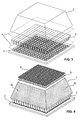
- Fig. 1 shows an embodiment, wherein the scintillator 1 is a mono crystal having a truncated pyramid shape with all faces except the bottom base face BF (better visible in Fig. 2 ) covered with an absorbing layer AL and wherein a scintillation-light-incidence-angle-constraining (SLIAC) element, e.g. an array of concentrators 3, is optically coupled to the scintillation light transparent bottom face of the truncated pyramid mono crystal scintillator in order to guide the scintillation light onto a position sensitive photo sensor 2.
- SLIAC scintillation-light-incidence-angle-constraining
- the coupling medium can be a thin layer (with a thickness less than 250 micrometer) of silicone gel with a refraction index between 1.4 and 1.5.
- the coupling medium is air.
- the absorbing layer(s) may be provided as coating(s) or paint(s) applied individually or all together to the surface(s) of the scintillator. They may also be provided as e.g. a cap or cover or surrounding, which is rigid and optically coupled to the scintillator (or the absorbing layer may be provided as a layer provided on the surface of such a cap, cover or surrounding and being supported thereby).
- the absorbing layers of different faces of the scintillator may be provided as one layer covering multiple faces or as a plurality of layers each covering (at least a portion) of one face.
- a faceplate / a plurality of faceplates could be used to guide the scintillation light onto a position sensitive photo sensor 2.
- At least one faceplate and an array of concentrators may be used together, with for example a faceplate or a plurality of faceplates (not shown) coupled between the array of concentrators (3) and the bottom face BF of the scintillator.
- Fig. 2 shows a transversal view of the exemplary embodiment presented in Fig.1 , where one can see that the bottom face BF of the scintillator 1 is not covered by an absorbing layer AL, but that top base face TF and lateral faces LF are and that the position sensitive photo sensor 2 is located below the concentrator array at bottom face, to measure the scintillation photons exiting the scintillator through the bottom face and guided by a scintillation-light-incidence-angle-constraining (SLIAC) element, e.g. the concentrators 3.
- SLIAC scintillation-light-incidence-angle-constraining
- An absorbing layer covering a face of the scintillator may be in direct contact with the face or may be optically coupled to such a face.
- Fig.3 is a transparent exploded view version of the exemplary embodiment shown in Fig.1 where the optic coupling medium layers 4 between scintillator and concentrators and position sensitive photo sensor and concentrators are shown.
- This optic coupling medium layers are thin as compared to the thickness of the scintillator, the SLIAC element, e.g. the concentrators 3, or the position sensitive photo sensor 2.
- a faceplate/faceplates could be optically coupled to a scintillation light transparent face to which a position sensitive photo sensor is optically coupled.
- Fig. 4 shows an exemplary embodiment, wherein top base and bottom face of the scintillator are transparent to scintillation light and wherein the gamma rays enter at the top face and a position sensitive photo sensor 2 (with or without concentrators in front of it) is optically coupled to the bottom face and wherein in addition a faceplate 5 can be optically coupled between the top face and a retroreflector 6.
- a position sensitive photo sensor 2 with or without concentrators in front of it
- a faceplate 5 can be optically coupled between the top face and a retroreflector 6.
- a position sensitive photo sensor 2' is mounted on the top face of truncated pyramid shaped scintillator.
- a scintillation-light-incidence-angle-constraining (SLIAC) element e.g. an array of concentrators 3 (which can be of type CPC, CPCa, TA, TAa or any other concentrator type) and/or a faceplate/s, can be optionally be coupled between said top face and position sensitive photo sensor 2'.
- SLIAC scintillation-light-incidence-angle-constraining
- Fig. 5b shows an example of an embodiment, wherein a photo sensor 2' is mounted to the top face of the scintillator, the face of entrance of the gamma rays.
- a further photo sensor 2 and a scintillation-light-incidence-angle-constraining (SLIAC) element e.g. an array of concentrators 3 (which can be of type CPC, CPCa, TA, TAa or any other concentrator type) and/or a faceplate/s, is attached to the bottom face of the scintillator.
- SLIAC scintillation-light-incidence-angle-constraining
- a second scintillation-light-incidence-angle-constraining (SLIAC) element e.g. a second array of concentrators and/or a faceplate/s, could be used to guide the light towards the photo sensor 2'.
- SLIAC scintillation-light-incidence-angle-constraining
- gamma ray scintillation detectors can be used to construct gamma ray detector arrays, whose shape is fitted to specific purposes, such as a tube or ring structure used in medical diagnosis.
- Fig. 6 Scintillation-light-incidence-angle-constraining (SLIAC) elements, e.g. concentrators and/or faceplates, guiding the light towards a photo sensor can be optically coupled in front of a photo sensor in any of the exemplary arrangements of a gamma ray scintillation detector according to the invention described here.
- Concentrators can be of type CPC, CPCa, TA or TAa and can be arranged in arrays of various sizes. Shown here for example is a 16x16 array of concentrators 3.
- Fig. 7 Transversal views are shown of a compound parabolic concentrator (CPC) on the left and an angle transformer (TA) concentrator on the right. Light incidence is from the top and the half light acceptance angles are denoted by ⁇ 1 and half light exit angles are denoted by ⁇ 2 .
- CPC compound parabolic concentrator
- TA angle transformer
- said half light acceptance angles are the maximum half light acceptance angles.
- a full light acceptance angle is two times its half light acceptance angle.
- the half exit angle of the CPC is ⁇ /2 whereas the half exit angle of the TA is less than ⁇ /2.
- the TA is characterized by having sides composed of a parabola DQ and a flat mirror QB. Exemplary light paths for the TA are denoted with r1, r2 and r3.
- Fig. 8 A transversal view is shown of an exemplary adapted angle transformer (TAa) concentrator with a curvature radius CR and draft angle DA.
- TAa angle transformer
- Fig. 9 A perspective view of an exemplary 8x1 matrix of adapted angle transformer (TAa) concentrators is shown, which has been moulded with curvature radii of CR and draft angles of DA.
- TAa adapted angle transformer
Landscapes
- Physics & Mathematics (AREA)
- Health & Medical Sciences (AREA)
- Life Sciences & Earth Sciences (AREA)
- General Physics & Mathematics (AREA)
- High Energy & Nuclear Physics (AREA)
- Molecular Biology (AREA)
- Spectroscopy & Molecular Physics (AREA)
- Measurement Of Radiation (AREA)
- Nuclear Medicine (AREA)
Abstract
a scintillator, a position sensitive photo sensor and at least one scintillation-light-incidence-angle-constraining, SLIAC, element, wherein
the scintillator has a plurality of faces; and wherein the position sensitive photo sensor is arranged to detect scintillation photons exiting a scintillation photons transparent face of the scintillator, and wherein at least a portion or the whole of at least one scintillator face is covered with an absorbing layer, which is arranged to absorb scintillation photons created by scintillation events due to the interaction of incoming gamma rays with the scintillator, and wherein the scintillation-light-incidence-angle-constraining, SLIAC, element is optically coupled between a scintillation photons transparent face of the scintillator and the position sensitive photo sensor and the scintillation-light-incidence-angle-constraining, SLIAC,
element is configured to guide the scintillation photons exiting the scintillator towards the position sensitive photo sensor, and wherein the scintillation-light-incidence-angle-constraining, SLIAC, element restricts the maximum allowed half light acceptance angle for the scintillation light hitting the position sensitive photo sensor to less than 45°.
Description
- The invention relates to the design of scintillation detectors as used in Nuclear imaging systems like Single-Photon Emission Computed Tomography (SPECT) or Positron Emission Tomography (PET) for the purpose of medical diagnosis.
- However it is to be understood that the present invention is also applicable in many other technical fields, as for example in astrophysical gamma ray telescopes or in examining rocks and minerals in geophysics.
- A wide range of medical image techniques is available for the diagnosis and treatment of diseases. One can differentiate between morphological imaging, such as in Computed Tomography (CT), Magnetic Resonance Imaging (MRI), X-ray, Ultrasound, etc. or functional imaging as in Gamma Ray Radiography, Single-Photon Emission Computed Tomography (SPECT) or Positron Emission Tomography (PET).
- Nuclear medicine is a special branch of medicine where physiological processes can be imaged by detecting the radiation from radioactive tracing substances injected into regions of interest (such as organs, bones, tissue, etc.) of the object under examination.
- In the case of PET, when the decaying radioactive tracer emits a positron, the positron annihilates with an electron creating a pair of high-energy gamma ray photons which are emitted in opposite directions. To detect the produced gamma rays, in general scintillation crystal detectors are used in the following way.
- In the case of PET, when a gamma ray photon enters the crystal it interacts with the atoms of the crystal, creating a flash of isotropically emitted lower energy photons following the excitation or ionization of the crystal atoms. In this so called scintillation event the energy of the gamma ray photons is thus transformed into lower energy (usually visible range) photons, which then can be measured by photo sensors. Furthermore the energy of the lower energy photons is hereby proportional to the energy of the incident gamma ray photons.
- When two gamma ray photon detections at opposite locations are made at the same or almost the same time (within a tolerance of a few nano seconds, due to different photon travel distances to the detectors) they are assumed to have been created in the same annihilation process. It is then known that the origin of this gamma ray pair emission must lie on the line connecting the two detection positions. This line is commonly referred to as line of response (LOR, see also
US2010/0044571A1 ). The cross section of a plurality of gamma ray pair detections and LORs can then be used to create a three dimensional map of the region of interest, where the concentration of the radioactive tracers is the highest. - The photo sensors used to measure the scintillation photons are normally position sensitive photomultiplier tubes (PMT) or the recently proposed semiconductor based detectors such as silicon multipliers (SiPM). The SiPMs usually consist of an array of avalanche photo diodes operating in Geiger mode. While SiPMs need less supply voltages than PMTs they suffer from thermal background noise, which increases proportionally to the square root of the covered detector surface area. It is therefore desirable to keep the active SiPM detector area as small as possible, but without reducing the light emitting area of the scintillator.
- As mentioned above the energy distribution measured by the photo sensor of such gamma ray cameras is proportional to the energy distribution of the incident gamma ray and so allows to discriminate between the energy of the original incident gamma radiation and secondary radiation such as background radiation or Compton scattered events. Furthermore the detected scintillation light contains information on the spatial location of the scintillation event inside the scintillator and hence on the source of the gamma radiation, the region of interest to be imaged.
- Prior art documents
US 4,150,292 andUS 6,858,847 are describing embodiments of such detectors in the field of Nuclear Imaging. - It is known that scintillator based gamma ray detectors have a poorer energy resolution than solid state high purity Germanium detectors. However scintillation detectors are still the most common type of detectors used due to their moderate costs, their high efficiency, applicability on large scales and the possibility to operate at room temperatures.
- In recent years considerably effort has been put into improving the energy resolution of scintillation detectors by maximizing the collection efficiency of the scintillation light created following the absorption of the gamma ray photons inside the scintillator. Computer simulations and experiments have shown that the ability to capture this light is strongly influenced by the geometry of the scintillator, the coating material of its outer surface and the scintillator-photo detector coupling.
- For example a diffuse reflecting optical finish increases the amount of light reaching the photo sensor, whereas using only a specular reflector (i.e. a polished surface) has the opposite effect. The best materials to wrap in light efficient scintillators have a high diffusive reflectivity. Polytetraflouroethylene (PTFE, Teflon) for example is a common material used to coat the outer surface of a scintillator. Recent work
US 2011/0017916 A1 shows how to combine a diffuse and specular reflective layer to increase light collection efficiency, however at the expense of worsening the information on the original distribution of the scintillation light. InUS 2011/0017916 A1 the objective is to collect all light, regardless of its spatial origin, thereby loosing spatial resolution. - In
US 2010/0044571 A1 a photo sensor is mounted onto the scintillator surface of entry of the gamma ray to increase spatial resolution, exploiting the fact that most scintillation events are occurring close to the surface of entry due to the exponential interaction probability. However, such a photo-sensor-on-entrance-surface configuration has the disadvantage that the gamma radiation is attenuated when traversing the photo sensor, which can lead to significant losses at lower energies. - The light distribution of a scintillation event measured by the position sensitive photo sensor, i.e. scintillation light intensity as a function of position on photo sensor depends on the three-dimensional position of the scintillation event inside the scintillator. From the centroid position, the width and higher moments of the light distribution measured by the photo sensor, the original location of the scintillation event can be reconstructed, as shown in
EP1617237A1 . The accuracy of how well the location of the scintillation event can be determined depends on the dispersion of the scintillation light before reaching the position sensitive photo sensor. In a state-of-the-art scintillator reflections at the scintillator faces increase the light collection efficiency but also lead to a broadening, respectively blurring of the light distribution received by the photo sensor, resulting in less accurate estimates of the three-dimensional scintillation event position, and therefore in a loss of spatial resolution of the gamma ray detector. - Current means of improving the spatial resolution within the field of view of the gamma ray camera commonly only relate to the use of different types of collimators mounted in front of the gamma ray detector in order to filter the gamma rays before the occurrence of a scintillation event (Kimiaei et al., 1996, Journal of Nuclear Medicine, Vol. 37. No. 8, p1417-1421).
- The objective technical problem to be solved is then to improve a gamma ray scintillation detector, in particular with respect to its spatial resolution.
- This said problem is solved by a gamma ray scintillation detector apparatus according to
claim 1. Preferred embodiments are disclosed in the dependent claims. - An apparatus according to
claim 1 has the advantage, that it preserves the original light distribution of the scintillation event photons and hence better constrains the information on the location of scintillation events inside the scintillator to achieve a higher spatial resolution of the gamma ray emitting region, i.e. the region of interest, as compared to the state of the art. - This advantage is achieved thanks to the synergy of two features inherent to the invention.
- First the absorbing layer covering (at least a portion of) at least one face of the scintillator reduces internal reflection of the scintillation light, thereby reducing the scintillation light dispersion inside the scintillator and so increases the spatial resolution of the gamma ray detector.
- Secondly the use of at least one scintillation-light-incidence-angle-constraining (SLIAC) element such as concentrator(s) and/or faceplate(s) enables to further reduce the internal scintillation light dispersion of the scintillator by restricting the range of allowed incidence angles of scintillation light guided to the position sensitive photo sensor(s) so that in the end a minimal scintillation light dispersion is reached, which would have been impossible to achieve by the use of absorbing layers or SLIACs alone.
- A SLIAC element can be for example configured to restrict the view of the position sensitive photo sensor for received scintillation light to maximum scintillation half light acceptance angles of less than 45°, i.e. full (= 2 x half) light acceptance angles of less than 90°.
- The absorbing layer can be of any type which absorbs more than 90%, or at least more than 50% of the incident scintillation photons in the visible energy range, created by the scintillation events due to the interaction of incoming gamma rays with the scintillator. For example it can be black paint or a black epoxy coating.
- The absorbing layer may also be provided as a rigid body or as being supported by a rigid body, and which is optically coupled to the face(s) of the scintillator.
- For clarity we note that we refer to scintillator faces which are not covered by an absorbing layer, as scintillator faces transparent to scintillation photons, respectively as scintillator faces emitting scintillation photons.
- Furthemore, unless noted otherwise, the here exemplary described photo sensors are to be understood as position sensitive photo sensors.
- Preferably a face of a scintillator or a portion of it, which is covered with an absorbing layer, is covered by at least 50 % of the surface of that face of the scintillator.
- Scintillation-light-incidence-angle-constraining (SLIAC) elements such as concentrators and/or faceplates can be optically coupled between the scintillation light emitting face of the scintillator and the photo sensor to guide / channel and/or concentrate the emitted scintillation light onto the photo sensor, increasing the spatial resolution of the gamma ray detector, by restricting the allowed range of the maximum full/half light acceptance angles.
- The concentrators can be of any type. For example they can be angle transformer concentrators (TAs), which are characterized by having lateral faces composed of two portions, a parabolic surface and a straight flat surface. However, also compound parabolic concentrators (CPCs), which have the shape of a rotated parabolic section, can be used.
- The CPC or the TA concentrators can also be so called adapted concentrators (CPCa, TAa), meaning that they are adapted to specific draft angle and curvature requirements of the fabrication process. The use TAs/TAas can be preferred, since they can possess less cross-talk noise (unwanted light leakage) than CPCs/CPCas when arranged into an array of concentrators.
- The use of concentrators as SLIACs also can have the advantage that the photo sensor area can be made smaller then the scintillation light emitting area of the scintillator face and so unwanted thermal noise of the photo sensor can be reduced.
- Since TAs/TAas can have smaller light exit angles than CPCs/CPCas, using TAs/TAas can permit to use even smaller/more compact photo sensors as in the case of using CPCs/CPCas and thermal noise of the photo sensor can be further minimized.
- To allow a dense packing of concentrators, better matching of photo sensor shape and concentrator shape, as well as minimizing dead spaces on the photo sensor, the scintillation light entry and scintillation exit faces of the concentrators can be of rectangular, preferably squared, shape.
- In a preferred exemplary arrangement of the invention the geometry of the scintillator in an apparatus according to
claim 1 is characterized by having a top base face, which is the face-of-entrance for the gamma rays, a bottom base face opposite to the top base face and a plurality of lateral faces. - Covering more faces or a larger portion of the scintillator with an absorbing layer can reduce the scintillation light dispersion even further and consequently also can further increase the spatial resolution of the gamma ray detector.
- Arrangements of the invention, wherein all lateral faces or all faces except the face facing towards the position sensitive photo sensor are covered with an absorbing layer therefore have the advantage that the expected spatial resolution is higher, as compared to scintillators with less faces covered by an absorbing layer.
- According to another preferred exemplary arrangement, a gamma ray detector apparatus can comprise a position sensitive photo sensor and concentrators mounted to the scintillator on the face-of-entrance of the gamma rays. This configuration exploits the fact that the most scintillation events occur close to the face-of-entrance of the scintillator, due to the exponential increase of the gamma-ray-scintillator-interaction-probability.
- In a further envisioned embodiment position sensitive photo sensors and concentrators are optically coupled to two faces of the scintillator, namely to the face-of-entrance (or top base face) of the gamma rays and to the face opposite the face-of-entrance (or bottom base face). As mentioned above concentrators of any type (i.e. TA, TAs, CPC, CPCa) can be used for each position sensitive photo sensor / position sensitive photo sensor array to concentrate the scintillation light.
- As already mentioned above also faceplates as SLIACs can be used for filtering the scintillation light by allowing only scintillation photons with specific incident angles to pass through, and in particular faceplates that can restrict the maximum scintillation half light acceptance angles to less than 45°.
- More specifically also faceplates with numerical apertures between 0.58 and 1.00 can be used, thereby further reducing the range of allowed maximum half light acceptance angles for incident scintillation light to between 19° and 34°.
- An additional exemplary arrangement of the invention can be a gamma ray detector according to any of the previously described arrangements, wherein the shape of the scintillator is a prismatoid, such as a truncated pyramid.
- A truncated pyramidal shaped scintillator has the advantage to enable dense packing of a plurality of gamma ray detectors into ring-like or tube-like configurations useful to enclose an object to be examined. In addition to geometrical considerations, it also reduces scintillator border effects.
- The scintillators used in any of the here described examples for embodiments can be mono crystals or pixelated crystals. Preferably the scintillator however is a mono crystal, since pixelated crystals introduce more dead space areas in the gamma ray detector, thus providing less sensitivity of the detector as compared to mono crystals as scintillators.
- Alternatively the scintillator material in a preferred exemplary embodiment can also be plastic, ceramic or glass.
- The position sensitive photo sensor used in any of the here described exemplary embodiments can be an array of position sensitive photo sensor or a single position sensitive photo sensor covering a scintillation light transparent face of the scintillator, i.e. a face not covered by an absorbing layer. The photo sensor type can be of silicium based photo multiplier type or of avalanche photo diode type or of any other type sensitive to the position and energy of incident scintillation event photons.
- An arrangement of the invention which has the advantage of being more light collection efficient than the other here described embodiments, comprises a retroreflector optically coupled to a scintillation light transparent scintillator face opposite to the scintillation light transparent scintillator face, to which the position sensitive photo sensor and concentrators are optically coupled and wherein at least one of the remaining scintillator faces is covered by an absorbing layer.
- Optionally, a faceplate / an additional faceplate or a plurality of faceplates can be optically coupled between the retroreflector and the scintillation light transparent scintillator face, to which the retroreflector is optically coupled to. In other words there can be an additional faceplate or a plurality of faceplates coupled to a scintillation light transparent scintillator face other than the scintillation light transparent scintillator face to which the position sensitive photo sensor is coupled to.
- The following figures serve as exemplary embodiments of the invention.
- Fig.1:
- A gamma ray detector including a
scintillator 1, aphoto sensor 2, and a scintillation-light-incidence-angle-constraining (SLIAC) element,e.g. concentrator array 3. - Fig. 2:
- Transversal view of
Fig. 1 . - Fig. 3:
- Exploded view of gamma ray detector of
Fig.1 showing the layers 4 of the optic coupling medium. - Fig. 4:
- Partially exploded view of a of gamma ray detector of
Fig.1 withadditional faceplate 5 and retroreflector 6. - Fig. 5a:
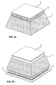
- Gamma ray detector with photo sensor 2' and concentrators located at the scintillator face-of-entrance of gamma rays.
- Fig. 5b:
- Gamma ray detector with a photo sensor 2' mounted to the scintillator face-of-entrance of the gamma rays and a
photo sensor 2 and concentrators at the bottom face of thescintillator 1. - Fig. 6:
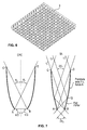
- An array of concentrators.
- Fig. 7:
- Transversal views of compound parabolic concentrator (CPC) and angle transformer (TA) concentrator.
- Fig. 8:
- Transversal view of an adapted angle transformer (TAa) concentrator.
- Fig. 9:
- Perspective view of a matrix of adapted angle transformer (TAa) concentrators.
-
Fig. 1 shows an embodiment, wherein thescintillator 1 is a mono crystal having a truncated pyramid shape with all faces except the bottom base face BF (better visible inFig. 2 ) covered with an absorbing layer AL and wherein a scintillation-light-incidence-angle-constraining (SLIAC) element, e.g. an array ofconcentrators 3, is optically coupled to the scintillation light transparent bottom face of the truncated pyramid mono crystal scintillator in order to guide the scintillation light onto a positionsensitive photo sensor 2. Two of four lateral faces LF and the top base face TF are visible. The area of the top base face TF is smaller than the area of the bottom base face BF. - At this point, we also like to note that when referring to optic coupling of optical elements, we refer to the use of an optical medium such as silicone, grease or gel, thermal plastic or any other suitable material with a refraction index that reduces internal reflections, especially reflections on the surface of the photo sensor. For example the coupling medium can be a thin layer (with a thickness less than 250 micrometer) of silicone gel with a refraction index between 1.4 and 1.5. However it is also possible that the coupling medium is air.
- The absorbing layer(s) may be provided as coating(s) or paint(s) applied individually or all together to the surface(s) of the scintillator. They may also be provided as e.g. a cap or cover or surrounding, which is rigid and optically coupled to the scintillator (or the absorbing layer may be provided as a layer provided on the surface of such a cap, cover or surrounding and being supported thereby). The absorbing layers of different faces of the scintillator may be provided as one layer covering multiple faces or as a plurality of layers each covering (at least a portion) of one face.
- In place of the concentrators, which can be of any type as described in the general summary of the invention, also a faceplate / a plurality of faceplates (not shown) could be used to guide the scintillation light onto a position
sensitive photo sensor 2. - Furthermore it is possible that at least one faceplate and an array of concentrators may be used together, with for example a faceplate or a plurality of faceplates (not shown) coupled between the array of concentrators (3) and the bottom face BF of the scintillator.
-
Fig. 2 shows a transversal view of the exemplary embodiment presented inFig.1 , where one can see that the bottom face BF of thescintillator 1 is not covered by an absorbing layer AL, but that top base face TF and lateral faces LF are and that the positionsensitive photo sensor 2 is located below the concentrator array at bottom face, to measure the scintillation photons exiting the scintillator through the bottom face and guided by a scintillation-light-incidence-angle-constraining (SLIAC) element, e.g. theconcentrators 3. - An absorbing layer covering a face of the scintillator may be in direct contact with the face or may be optically coupled to such a face.
-
Fig.3 is a transparent exploded view version of the exemplary embodiment shown inFig.1 where the optic coupling medium layers 4 between scintillator and concentrators and position sensitive photo sensor and concentrators are shown. This optic coupling medium layers are thin as compared to the thickness of the scintillator, the SLIAC element, e.g. theconcentrators 3, or the positionsensitive photo sensor 2. - As already mentioned above alternatively or additionally to the concentrators a faceplate/faceplates (not shown) could be optically coupled to a scintillation light transparent face to which a position sensitive photo sensor is optically coupled.
-
Fig. 4 shows an exemplary embodiment, wherein top base and bottom face of the scintillator are transparent to scintillation light and wherein the gamma rays enter at the top face and a position sensitive photo sensor 2 (with or without concentrators in front of it) is optically coupled to the bottom face and wherein in addition afaceplate 5 can be optically coupled between the top face and a retroreflector 6. Such an exemplary arrangement has the advantage of increasing the scintillation light collection efficiency as compared to arrangements with all but one face covered by an absorbing layer. - In a further alternative exemplary embodiment (
Fig. 5a ), a position sensitive photo sensor 2' is mounted on the top face of truncated pyramid shaped scintillator. Again a scintillation-light-incidence-angle-constraining (SLIAC) element, e.g. an array of concentrators 3 (which can be of type CPC, CPCa, TA, TAa or any other concentrator type) and/or a faceplate/s, can be optionally be coupled between said top face and position sensitive photo sensor 2'. - Here for example all scintillator faces except the top face are covered by an absorbing layer.
-
Fig. 5b shows an example of an embodiment, wherein a photo sensor 2' is mounted to the top face of the scintillator, the face of entrance of the gamma rays. Afurther photo sensor 2 and a scintillation-light-incidence-angle-constraining (SLIAC) element, e.g. an array of concentrators 3 (which can be of type CPC, CPCa, TA, TAa or any other concentrator type) and/or a faceplate/s, is attached to the bottom face of the scintillator. Here both top and bottom face of the scintillator are transparent to scintillation light. - Although not shown in the drawing it is further possible that in the configuration of
Fig. 5b a second scintillation-light-incidence-angle-constraining (SLIAC) element, e.g. a second array of concentrators and/or a faceplate/s, could be used to guide the light towards the photo sensor 2'. - Also a plurality of gamma ray scintillation detectors according to any of the here described exemplary embodiments can be used to construct gamma ray detector arrays, whose shape is fitted to specific purposes, such as a tube or ring structure used in medical diagnosis.
-
Fig. 6 : Scintillation-light-incidence-angle-constraining (SLIAC) elements, e.g. concentrators and/or faceplates, guiding the light towards a photo sensor can be optically coupled in front of a photo sensor in any of the exemplary arrangements of a gamma ray scintillation detector according to the invention described here. Concentrators can be of type CPC, CPCa, TA or TAa and can be arranged in arrays of various sizes. Shown here for example is a 16x16 array ofconcentrators 3. -
Fig. 7 : Transversal views are shown of a compound parabolic concentrator (CPC) on the left and an angle transformer (TA) concentrator on the right. Light incidence is from the top and the half light acceptance angles are denoted by ⊝1 and half light exit angles are denoted by ⊝2. - In fact in the shown light path geometries, said half light acceptance angles are the maximum half light acceptance angles.
- For completeness we note that a full light acceptance angle is two times its half light acceptance angle. The half exit angle of the CPC is π/2 whereas the half exit angle of the TA is less than π/2. The TA is characterized by having sides composed of a parabola DQ and a flat mirror QB. Exemplary light paths for the TA are denoted with r1, r2 and r3.
-
Fig. 8 : A transversal view is shown of an exemplary adapted angle transformer (TAa) concentrator with a curvature radius CR and draft angle DA. -
Fig. 9 : A perspective view of an exemplary 8x1 matrix of adapted angle transformer (TAa) concentrators is shown, which has been moulded with curvature radii of CR and draft angles of DA. - For completeness we note it is assumed clear that further configurations, respectively combinations of the optical elements used in the preceding exemplary embodiments are possible as alternative exemplary embodiments of the same inventive concept.
Claims (15)
- An apparatus to detect gamma rays, comprising:a scintillator, a position sensitive photo sensor and at least one scintillation-light-incidence-angle-constraining, SLIAC, element, wherein the scintillator has a plurality of faces; andwherein the position sensitive photo sensor is arranged to detect scintillation photons exiting a scintillation photons transparent face of the scintillator, andwherein at least a portion or the whole of at least one scintillator face is covered with an absorbing layer, which is arranged to absorb scintillation photons created by scintillation events due to the interaction of incoming gamma rays with the scintillator, andwherein the scintillation-light-incidence-angle-constraining, SLIAC, element is optically coupled between a scintillation photons transparent face of the scintillator and the position sensitive photo sensor and the scintillation-light-incidence-angle-constraining, SLIAC, element is configured to guide the scintillation photons exiting the scintillator towards the position sensitive photo sensor, andwherein the scintillation-light-incidence-angle-constraining, SLIAC, element restricts the maximum allowed half light acceptance angle for the scintillation light hitting the position sensitive photo sensor to less than 45°.
- An apparatus according to claim 1, wherein the scintillation-light-incidence-angle-constraining, SLIAC, element is at least one of an array of concentrators and/or a faceplate/s.
- An apparatus according to claim 2, wherein the concentrators are angle transformer or adapted angle transformer, or compound parabolic or adapted compound parabolic concentrators.
- An apparatus according to any of the preceding claims, wherein the scintillator has a top face, which is the face of entrance of the gamma rays, a bottom face opposite to the top face and a plurality of lateral faces.
- An apparatus according to claim 4, wherein at least a portion or the whole of all lateral faces of the scintillator are covered with an absorbing layer.
- An apparatus according to claim 4 or 5 , wherein at least a portion or the whole of all lateral faces of the scintillator and the base face are covered with an absorbing layer, and the scintillation photons transparent face of the scintillator is the top face.
- An apparatus according to claim 4 or 5, wherein at least a portion or the whole of all lateral faces of the scintillator and the top face are covered with an absorbing layer, and the scintillation photons transparent face of the scintillator is the bottom face.
- An apparatus according to claim 5, wherein the position sensitive photo sensor is optically coupled to the bottom face and a second position sensitive photo sensor is optically coupled to the top face of the scintillator.
- An apparatus according to any of the preceding claims, wherein a faceplate is optically coupled to a face of the scintillator transparent to scintillation photons; and wherein the faceplate allows only scintillation photons with specific incident angles to pass through, or reduces the range of allowed maximum half light acceptance angles for the incident scintillation light to between 19° and 34°.
- An apparatus according to any of the preceding claims, wherein the scintillator has a truncated pyramid shape.
- An apparatus according to any of the preceding claims, wherein the scintillator is at least of one of the types in a list comprising mono crystal and pixelated crystal.
- An apparatus according to any of the preceding claims 1 to 11, wherein the scintillator material is at least one of the types in a list comprising, plastic, ceramic, glass.
- An apparatus according to any of the preceding claims, wherein the position sensitive photo sensor is at least of one configuration in a list comprising, a position sensitive photo sensor array covering the area of a scintillator face transparent to scintillation photons, a single position sensitive photo sensor covering the area of a scintillator face transparent to scintillation photons; and wherein the type of photo sensor is at least one of the types in a list comprising silicium based photo multiplier and avalanche photo diode.
- An apparatus according to any of the preceding claims, except claims 6 and 7, wherein a retroreflector is optically coupled to the scintillation photons transparent face of the scintillator opposite the scintillation photons transparent scintillator face, to which the position sensitive photo sensor is optically coupled.
- An apparatus according to claim 14, wherein a faceplate is optically coupled between retroreflector and scintillator and wherein the faceplate allows only scintillation photons with specific incident angles to pass through, or reduces the range of allowed maximum half light acceptance angles for the incident scintillation light to between 19° and 34°.
Priority Applications (4)
| Application Number | Priority Date | Filing Date | Title |
|---|---|---|---|
| ES12008547T ES2727282T3 (en) | 2012-12-21 | 2012-12-21 | Range lightning scintillation detector that preserves the original scintillation light distribution |
| EP12008547.7A EP2746816B1 (en) | 2012-12-21 | 2012-12-21 | Gamma ray scintillation detector preserving the original scintillation light distribution |
| US14/134,107 US9915739B2 (en) | 2012-12-21 | 2013-12-19 | Gamma ray scintillation detector preserving the original scintillation light distribution |
| JP2013262322A JP2014122898A (en) | 2012-12-21 | 2013-12-19 | Gamma ray scintillation detector preserving original scintillation light distribution |
Applications Claiming Priority (1)
| Application Number | Priority Date | Filing Date | Title |
|---|---|---|---|
| EP12008547.7A EP2746816B1 (en) | 2012-12-21 | 2012-12-21 | Gamma ray scintillation detector preserving the original scintillation light distribution |
Publications (2)
| Publication Number | Publication Date |
|---|---|
| EP2746816A1 true EP2746816A1 (en) | 2014-06-25 |
| EP2746816B1 EP2746816B1 (en) | 2019-02-20 |
Family
ID=47602743
Family Applications (1)
| Application Number | Title | Priority Date | Filing Date |
|---|---|---|---|
| EP12008547.7A Not-in-force EP2746816B1 (en) | 2012-12-21 | 2012-12-21 | Gamma ray scintillation detector preserving the original scintillation light distribution |
Country Status (4)
| Country | Link |
|---|---|
| US (1) | US9915739B2 (en) |
| EP (1) | EP2746816B1 (en) |
| JP (1) | JP2014122898A (en) |
| ES (1) | ES2727282T3 (en) |
Cited By (6)
| Publication number | Priority date | Publication date | Assignee | Title |
|---|---|---|---|---|
| WO2016187447A1 (en) * | 2015-05-19 | 2016-11-24 | Protonvda Inc. | A proton imaging system for optimization of proton therapy |
| WO2018078203A1 (en) | 2016-10-25 | 2018-05-03 | General Equipment For Medical Imaging, S.A. | Method for generating nuclear images for nuclear-imaging devices with continuous crystal detectors |
| US10816678B2 (en) | 2016-02-26 | 2020-10-27 | Radialis Inc. | Tileable block detectors for seamless block detector arrays in positron emission mammography |
| US10918350B2 (en) | 2017-12-28 | 2021-02-16 | Board Of Trustees Of Northern Illinois University | Processing pipeline for prompt particle image reconstruction |
| RU2808532C1 (en) * | 2020-08-19 | 2023-11-29 | Циньхуа Юниверсити | Collimation detection unit, detection apparatus and spect-visualization system |
| CN119241067A (en) * | 2024-09-30 | 2025-01-03 | 山东大学 | A method for preparing a reconfigurable glass scintillator screen and its application in X-ray co-forming imaging |
Families Citing this family (14)
| Publication number | Priority date | Publication date | Assignee | Title |
|---|---|---|---|---|
| GB2522017B (en) * | 2014-01-08 | 2017-09-20 | Symetrica Ltd | Apparatus and methods for gamma ray detection |
| US9606245B1 (en) | 2015-03-24 | 2017-03-28 | The Research Foundation For The State University Of New York | Autonomous gamma, X-ray, and particle detector |
| JP6258895B2 (en) * | 2015-06-03 | 2018-01-10 | 三菱電機プラントエンジニアリング株式会社 | Radioactive contamination inspection equipment |
| TWI571243B (en) * | 2015-10-20 | 2017-02-21 | 行政院原子能委員會核能研究所 | Method for determining three dimensional location and energy of gamma incidence event and thereof device |
| EP4080249B1 (en) | 2016-04-15 | 2025-01-01 | Luxium Solutions, LLC | Photosensors arranged on a surface of a scintillator |
| JP2017215194A (en) * | 2016-05-31 | 2017-12-07 | 東芝メディカルシステムズ株式会社 | Detector and radiation diagnosis apparatus |
| AU2018285543B2 (en) | 2017-06-14 | 2023-10-05 | Hadal, Inc. | Systems and methods for virtual reality motion sickness prevention |
| CN108387923B (en) * | 2018-03-15 | 2023-10-20 | 西北核技术研究所 | Packaged scintillator and scintillation detector with photonic crystal layer |
| ES2757984B2 (en) | 2018-10-31 | 2021-02-16 | Univ Valencia Politecnica | DEVICE FOR THE DETECTION OF GAMMA RAYS WITH ACTIVE SEALS |
| PL3908856T3 (en) | 2019-01-08 | 2025-09-08 | The Research Foundation For The State University Of New York | PRISMATOID FIBER |
| CA3086757A1 (en) | 2019-02-15 | 2020-08-15 | The Research Foundation For The State University Of New York | High resolution depth-encoding pet detector with prismatoid light guide array |
| CN113614574B (en) * | 2019-03-29 | 2025-03-14 | 深圳帧观德芯科技有限公司 | Radiation detector with scintillator |
| JP7199332B2 (en) * | 2019-10-07 | 2023-01-05 | キヤノン電子管デバイス株式会社 | Method for manufacturing radiation detection module |
| GB202101278D0 (en) * | 2021-01-29 | 2021-03-17 | Serac Imaging Systems Ltd | Imaging device |
Citations (7)
| Publication number | Priority date | Publication date | Assignee | Title |
|---|---|---|---|---|
| US4150292A (en) | 1977-02-18 | 1979-04-17 | Ter Pogossian Michel M | Imaging device for computerized emission tomography |
| US6516044B1 (en) * | 2001-10-23 | 2003-02-04 | Ge Medical Systems Global Technology Co., Llc | Scintillation apparatus and method of light collection for use with a radiation emitting medical imaging scanner |
| US6858847B1 (en) | 1998-10-08 | 2005-02-22 | Siemens Medical Solutions Usa, Inc. | Circuit and method for energy discrimination of coincident events in coincidence detecting gamma camera system |
| EP1617237A1 (en) | 2003-04-10 | 2006-01-18 | Consejo Superior De Investigaciones Cientificas | Gamma ray detector with interaction depth coding |
| US20080073542A1 (en) * | 2006-09-22 | 2008-03-27 | Stefan Siegel | Light guide having a tapered geometrical configuration for improving light collection in a radiation detector |
| US20100044571A1 (en) | 2008-08-19 | 2010-02-25 | University Of Washington | Method for determining the three-dimensional position of a scintillation event |
| US20110017916A1 (en) | 2007-08-22 | 2011-01-27 | Koninklijke Philips Electronics N.V. | Reflector and light collimator arrangement for improved light collection in scintillation detectors |
Family Cites Families (14)
| Publication number | Priority date | Publication date | Assignee | Title |
|---|---|---|---|---|
| JPH1073667A (en) * | 1996-08-30 | 1998-03-17 | Shimadzu Corp | Radiation detector |
| GB2354369A (en) * | 1999-09-17 | 2001-03-21 | Secr Defence | Noise reduced semiconductor photon detectors |
| US6473486B2 (en) * | 2000-12-05 | 2002-10-29 | Ge Medical Systems Global Technology Co., Llc | System and method of computed tomography imaging using a focused scintillator and method of manufacturing |
| US20030021376A1 (en) * | 2001-07-26 | 2003-01-30 | Smith Steven Winn | High-resolution radiation detector |
| US20040227091A1 (en) * | 2003-05-14 | 2004-11-18 | Leblanc James Walter | Methods and apparatus for radiation detecting and imaging using monolithic detectors |
| WO2007011214A1 (en) | 2005-07-19 | 2007-01-25 | Milabs B.V. | Radiation detection apparatus |
| US7696482B1 (en) * | 2006-06-02 | 2010-04-13 | Radiation Monitoring Devices, Inc. | High spatial resolution radiation detector |
| JP2008185393A (en) * | 2007-01-29 | 2008-08-14 | Konica Minolta Medical & Graphic Inc | Scintillator panel |
| FR2948379B1 (en) * | 2009-07-21 | 2011-08-19 | Saint Gobain Cristaux Et Detecteurs | RARE EARTH HALIDE SCINTILLATOR COATED WITH AN ABSORBER OR LIGHT REFLECTOR |
| CN102597805B (en) * | 2009-11-12 | 2016-03-30 | 圣戈本陶瓷及塑料股份有限公司 | Blink Pixel Design and How It Works |
| US8399842B2 (en) * | 2009-12-07 | 2013-03-19 | Carestream Health, Inc. | Digital radiographic detector with bonded phosphor layer |
| CN103220978B (en) * | 2010-11-18 | 2017-02-22 | 皇家飞利浦电子股份有限公司 | PET‑CT system with single detector |
| WO2012093526A1 (en) * | 2011-01-04 | 2012-07-12 | 浜松ホトニクス株式会社 | Radiation detector |
| JP2012247281A (en) * | 2011-05-27 | 2012-12-13 | Fujifilm Corp | Radiographic apparatus, scintillator, and method for manufacturing the same |
-
2012
- 2012-12-21 ES ES12008547T patent/ES2727282T3/en active Active
- 2012-12-21 EP EP12008547.7A patent/EP2746816B1/en not_active Not-in-force
-
2013
- 2013-12-19 US US14/134,107 patent/US9915739B2/en not_active Expired - Fee Related
- 2013-12-19 JP JP2013262322A patent/JP2014122898A/en active Pending
Patent Citations (7)
| Publication number | Priority date | Publication date | Assignee | Title |
|---|---|---|---|---|
| US4150292A (en) | 1977-02-18 | 1979-04-17 | Ter Pogossian Michel M | Imaging device for computerized emission tomography |
| US6858847B1 (en) | 1998-10-08 | 2005-02-22 | Siemens Medical Solutions Usa, Inc. | Circuit and method for energy discrimination of coincident events in coincidence detecting gamma camera system |
| US6516044B1 (en) * | 2001-10-23 | 2003-02-04 | Ge Medical Systems Global Technology Co., Llc | Scintillation apparatus and method of light collection for use with a radiation emitting medical imaging scanner |
| EP1617237A1 (en) | 2003-04-10 | 2006-01-18 | Consejo Superior De Investigaciones Cientificas | Gamma ray detector with interaction depth coding |
| US20080073542A1 (en) * | 2006-09-22 | 2008-03-27 | Stefan Siegel | Light guide having a tapered geometrical configuration for improving light collection in a radiation detector |
| US20110017916A1 (en) | 2007-08-22 | 2011-01-27 | Koninklijke Philips Electronics N.V. | Reflector and light collimator arrangement for improved light collection in scintillation detectors |
| US20100044571A1 (en) | 2008-08-19 | 2010-02-25 | University Of Washington | Method for determining the three-dimensional position of a scintillation event |
Non-Patent Citations (3)
| Title |
|---|
| GIANCARLO BARBARINO, RICCARDO DE ASMUNDIS, GIANFRANCA DE ROSA, CARLOS MAXIMILIANO MOLLO, STEFANO RUSSO AND DANIELE VIVOLO (2011).: "Silicon Photo Multipliers Detectors Operating in Geiger Regime: an Unlimited Device for Future Applications", INTECH, vol. 5, 29 July 2011 (2011-07-29), pages 183 - 226, XP002698500, ISBN: 978-953-307-530-3, Retrieved from the Internet <URL:http://www.intechopen.com/books/photodiodes-world-activities-in-2011/silicon-photo-multipliers-detectors-operating-in-geiger-regime-an-unlimited-device-for-future-applic> [retrieved on 20130607], DOI: 10.5772/21521. * |
| KIMIAEI ET AL., JOURNAL OF NUCLEAR MEDICINE, vol. 37, no. 8, 1996, pages 1417 - 1421 |
| NABIN SARMAH ET AL: "Evaluation and optimization of the optical performance of low-concentrating dielectric compound parabolic concentrator using ray-tracing methods", APPLIED OPTICS, OPTICAL SOCIETY OF AMERICA, WASHINGTON, DC; US, vol. 50, no. 19, 1 July 2011 (2011-07-01), pages 3303 - 3310, XP001564103, ISSN: 0003-6935, [retrieved on 20110701], DOI: 10.1364/AO.50.003303 * |
Cited By (12)
| Publication number | Priority date | Publication date | Assignee | Title |
|---|---|---|---|---|
| WO2016187447A1 (en) * | 2015-05-19 | 2016-11-24 | Protonvda Inc. | A proton imaging system for optimization of proton therapy |
| CN107850675A (en) * | 2015-05-19 | 2018-03-27 | 普罗通弗达有限公司 | Proton Imaging Systems for Optimizing Proton Therapy |
| AU2016264493B2 (en) * | 2015-05-19 | 2020-12-03 | Protonvda Inc. | A proton imaging system for optimization of proton therapy |
| US11116459B2 (en) | 2015-05-19 | 2021-09-14 | Protonvda Llc | Proton imaging system for optimization of proton therapy |
| EP3298434B1 (en) * | 2015-05-19 | 2022-11-16 | Protonvda Inc. | A proton imaging system for optimization of proton therapy |
| US11684328B2 (en) | 2015-05-19 | 2023-06-27 | Protonvda Llc | Proton imaging system for optimization of proton therapy |
| US10816678B2 (en) | 2016-02-26 | 2020-10-27 | Radialis Inc. | Tileable block detectors for seamless block detector arrays in positron emission mammography |
| WO2018078203A1 (en) | 2016-10-25 | 2018-05-03 | General Equipment For Medical Imaging, S.A. | Method for generating nuclear images for nuclear-imaging devices with continuous crystal detectors |
| US10918350B2 (en) | 2017-12-28 | 2021-02-16 | Board Of Trustees Of Northern Illinois University | Processing pipeline for prompt particle image reconstruction |
| US11813105B2 (en) | 2017-12-28 | 2023-11-14 | Board Of Trustees Of Northern Illinois University | Processing pipeline for prompt particle image reconstruction |
| RU2808532C1 (en) * | 2020-08-19 | 2023-11-29 | Циньхуа Юниверсити | Collimation detection unit, detection apparatus and spect-visualization system |
| CN119241067A (en) * | 2024-09-30 | 2025-01-03 | 山东大学 | A method for preparing a reconfigurable glass scintillator screen and its application in X-ray co-forming imaging |
Also Published As
| Publication number | Publication date |
|---|---|
| EP2746816B1 (en) | 2019-02-20 |
| JP2014122898A (en) | 2014-07-03 |
| US9915739B2 (en) | 2018-03-13 |
| ES2727282T3 (en) | 2019-10-15 |
| US20140175296A1 (en) | 2014-06-26 |
Similar Documents
| Publication | Publication Date | Title |
|---|---|---|
| EP2746816B1 (en) | Gamma ray scintillation detector preserving the original scintillation light distribution | |
| US10281594B2 (en) | Gamma-ray Compton TOF camera system | |
| JP5944903B2 (en) | Interaction depth scintillation detector | |
| US8946643B2 (en) | Virtual pixelated detector for pet and/or spect | |
| CN101779145B (en) | A kind of radiation detection method | |
| CN101796428B (en) | Reduced edge effect detector | |
| US8779366B2 (en) | Pixelated scintillator array | |
| US11644584B2 (en) | Gamma radiation imaging device and imaging method thereof | |
| ES2757984B2 (en) | DEVICE FOR THE DETECTION OF GAMMA RAYS WITH ACTIVE SEALS | |
| US7049600B2 (en) | Scintillation crystal detection arrays for radiation imaging devices | |
| CN113260881B (en) | Pseudo-cylindrical light guide | |
| NL2020237B1 (en) | Active collimator for positron emission and single photon emission computed tomography | |
| WO2003089956A1 (en) | A biomedical nuclear and x-ray imager using high-energy grazing incidence mirrors | |
| WO2021148694A1 (en) | Device for the detection of gamma rays with interaction depth and time-of-flight encoding | |
| US20230092129A1 (en) | Gamma ray detector with planar symmetry, multi-pinhole collimator and variable sampling region | |
| Korevaar et al. | A pinhole gamma camera with optical depth-of-interaction elimination | |
| WO2020013689A1 (en) | Active collimator system comprising a monolayer of monolithic converters | |
| WO2016112135A1 (en) | Compact trapezoidal pet detector with light sharing | |
| US11150364B2 (en) | Crystal array, detector, medical detection device and method of manufacturing crystal array | |
| CN115685305A (en) | Gamma imaging device and imaging method thereof | |
| Furenlid et al. | SPECT imager design and data-acquisition systems | |
| CN113057664B (en) | Single photon emission tomography device | |
| Matthews et al. | Experimental and simulation results with the Depth-encoding Anger Detector |
Legal Events
| Date | Code | Title | Description |
|---|---|---|---|
| PUAI | Public reference made under article 153(3) epc to a published international application that has entered the european phase |
Free format text: ORIGINAL CODE: 0009012 |
|
| 17P | Request for examination filed |
Effective date: 20121221 |
|
| AK | Designated contracting states |
Kind code of ref document: A1 Designated state(s): AL AT BE BG CH CY CZ DE DK EE ES FI FR GB GR HR HU IE IS IT LI LT LU LV MC MK MT NL NO PL PT RO RS SE SI SK SM TR |
|
| AX | Request for extension of the european patent |
Extension state: BA ME |
|
| R17P | Request for examination filed (corrected) |
Effective date: 20141216 |
|
| RBV | Designated contracting states (corrected) |
Designated state(s): AL AT BE BG CH CY CZ DE DK EE ES FI FR GB GR HR HU IE IS IT LI LT LU LV MC MK MT NL NO PL PT RO RS SE SI SK SM TR |
|
| RAP1 | Party data changed (applicant data changed or rights of an application transferred) |
Owner name: BRUKER BIOSPIN AG Owner name: GENERAL EQUIPMENT FOR MEDICAL IMAGING S.A. (ONCOVI |
|
| STAA | Information on the status of an ep patent application or granted ep patent |
Free format text: STATUS: EXAMINATION IS IN PROGRESS |
|
| 17Q | First examination report despatched |
Effective date: 20180410 |
|
| GRAP | Despatch of communication of intention to grant a patent |
Free format text: ORIGINAL CODE: EPIDOSNIGR1 |
|
| STAA | Information on the status of an ep patent application or granted ep patent |
Free format text: STATUS: GRANT OF PATENT IS INTENDED |
|
| INTG | Intention to grant announced |
Effective date: 20180726 |
|
| GRAS | Grant fee paid |
Free format text: ORIGINAL CODE: EPIDOSNIGR3 |
|
| GRAA | (expected) grant |
Free format text: ORIGINAL CODE: 0009210 |
|
| STAA | Information on the status of an ep patent application or granted ep patent |
Free format text: STATUS: THE PATENT HAS BEEN GRANTED |
|
| AK | Designated contracting states |
Kind code of ref document: B1 Designated state(s): AL AT BE BG CH CY CZ DE DK EE ES FI FR GB GR HR HU IE IS IT LI LT LU LV MC MK MT NL NO PL PT RO RS SE SI SK SM TR |
|
| REG | Reference to a national code |
Ref country code: GB Ref legal event code: FG4D |
|
| RIN1 | Information on inventor provided before grant (corrected) |
Inventor name: SOLSONA, CESAR MOLINOS Inventor name: MASCARELL, JUAN VICENTE CATRET Inventor name: HERNANDEZ, NORIEL PAVON Inventor name: BAVIERA, JOSE MARIA BENLLOCH Inventor name: SALVADOR, CARLOS CORRECHER Inventor name: MARTINEZ, FILOMENO SANCHEZ Inventor name: MARTINEZ, ANTONIO JAVIER GONZALEZ |
|
| REG | Reference to a national code |
Ref country code: CH Ref legal event code: EP |
|
| REG | Reference to a national code |
Ref country code: DE Ref legal event code: R096 Ref document number: 602012056734 Country of ref document: DE |
|
| REG | Reference to a national code |
Ref country code: AT Ref legal event code: REF Ref document number: 1098936 Country of ref document: AT Kind code of ref document: T Effective date: 20190315 |
|
| REG | Reference to a national code |
Ref country code: IE Ref legal event code: FG4D |
|
| REG | Reference to a national code |
Ref country code: NL Ref legal event code: MP Effective date: 20190220 |
|
| REG | Reference to a national code |
Ref country code: LT Ref legal event code: MG4D |
|
| PG25 | Lapsed in a contracting state [announced via postgrant information from national office to epo] |
Ref country code: SE Free format text: LAPSE BECAUSE OF FAILURE TO SUBMIT A TRANSLATION OF THE DESCRIPTION OR TO PAY THE FEE WITHIN THE PRESCRIBED TIME-LIMIT Effective date: 20190220 Ref country code: FI Free format text: LAPSE BECAUSE OF FAILURE TO SUBMIT A TRANSLATION OF THE DESCRIPTION OR TO PAY THE FEE WITHIN THE PRESCRIBED TIME-LIMIT Effective date: 20190220 Ref country code: NO Free format text: LAPSE BECAUSE OF FAILURE TO SUBMIT A TRANSLATION OF THE DESCRIPTION OR TO PAY THE FEE WITHIN THE PRESCRIBED TIME-LIMIT Effective date: 20190520 Ref country code: PT Free format text: LAPSE BECAUSE OF FAILURE TO SUBMIT A TRANSLATION OF THE DESCRIPTION OR TO PAY THE FEE WITHIN THE PRESCRIBED TIME-LIMIT Effective date: 20190620 Ref country code: LT Free format text: LAPSE BECAUSE OF FAILURE TO SUBMIT A TRANSLATION OF THE DESCRIPTION OR TO PAY THE FEE WITHIN THE PRESCRIBED TIME-LIMIT Effective date: 20190220 |
|
| PG25 | Lapsed in a contracting state [announced via postgrant information from national office to epo] |
Ref country code: IS Free format text: LAPSE BECAUSE OF FAILURE TO SUBMIT A TRANSLATION OF THE DESCRIPTION OR TO PAY THE FEE WITHIN THE PRESCRIBED TIME-LIMIT Effective date: 20190620 Ref country code: NL Free format text: LAPSE BECAUSE OF FAILURE TO SUBMIT A TRANSLATION OF THE DESCRIPTION OR TO PAY THE FEE WITHIN THE PRESCRIBED TIME-LIMIT Effective date: 20190220 Ref country code: RS Free format text: LAPSE BECAUSE OF FAILURE TO SUBMIT A TRANSLATION OF THE DESCRIPTION OR TO PAY THE FEE WITHIN THE PRESCRIBED TIME-LIMIT Effective date: 20190220 Ref country code: LV Free format text: LAPSE BECAUSE OF FAILURE TO SUBMIT A TRANSLATION OF THE DESCRIPTION OR TO PAY THE FEE WITHIN THE PRESCRIBED TIME-LIMIT Effective date: 20190220 Ref country code: HR Free format text: LAPSE BECAUSE OF FAILURE TO SUBMIT A TRANSLATION OF THE DESCRIPTION OR TO PAY THE FEE WITHIN THE PRESCRIBED TIME-LIMIT Effective date: 20190220 Ref country code: GR Free format text: LAPSE BECAUSE OF FAILURE TO SUBMIT A TRANSLATION OF THE DESCRIPTION OR TO PAY THE FEE WITHIN THE PRESCRIBED TIME-LIMIT Effective date: 20190521 Ref country code: BG Free format text: LAPSE BECAUSE OF FAILURE TO SUBMIT A TRANSLATION OF THE DESCRIPTION OR TO PAY THE FEE WITHIN THE PRESCRIBED TIME-LIMIT Effective date: 20190520 |
|
| REG | Reference to a national code |
Ref country code: AT Ref legal event code: MK05 Ref document number: 1098936 Country of ref document: AT Kind code of ref document: T Effective date: 20190220 |
|
| REG | Reference to a national code |
Ref country code: ES Ref legal event code: FG2A Ref document number: 2727282 Country of ref document: ES Kind code of ref document: T3 Effective date: 20191015 |
|
| REG | Reference to a national code |
Ref country code: DE Ref legal event code: R082 Ref document number: 602012056734 Country of ref document: DE Representative=s name: GRUENECKER PATENT- UND RECHTSANWAELTE PARTG MB, DE Ref country code: DE Ref legal event code: R081 Ref document number: 602012056734 Country of ref document: DE Owner name: BRUKER SWITZERLAND AG, CH Free format text: FORMER OWNERS: BRUKER BIOSPIN AG, FAELLANDEN, CH; GENERAL EQUIPMENT FOR MEDICAL IMAGING, S.A., VALENCIA, ES Ref country code: DE Ref legal event code: R081 Ref document number: 602012056734 Country of ref document: DE Owner name: GENERAL EQUIPMENT FOR MEDICAL IMAGING, S.A., ES Free format text: FORMER OWNERS: BRUKER BIOSPIN AG, FAELLANDEN, CH; GENERAL EQUIPMENT FOR MEDICAL IMAGING, S.A., VALENCIA, ES |
|
| PG25 | Lapsed in a contracting state [announced via postgrant information from national office to epo] |
Ref country code: AL Free format text: LAPSE BECAUSE OF FAILURE TO SUBMIT A TRANSLATION OF THE DESCRIPTION OR TO PAY THE FEE WITHIN THE PRESCRIBED TIME-LIMIT Effective date: 20190220 Ref country code: RO Free format text: LAPSE BECAUSE OF FAILURE TO SUBMIT A TRANSLATION OF THE DESCRIPTION OR TO PAY THE FEE WITHIN THE PRESCRIBED TIME-LIMIT Effective date: 20190220 Ref country code: CZ Free format text: LAPSE BECAUSE OF FAILURE TO SUBMIT A TRANSLATION OF THE DESCRIPTION OR TO PAY THE FEE WITHIN THE PRESCRIBED TIME-LIMIT Effective date: 20190220 Ref country code: DK Free format text: LAPSE BECAUSE OF FAILURE TO SUBMIT A TRANSLATION OF THE DESCRIPTION OR TO PAY THE FEE WITHIN THE PRESCRIBED TIME-LIMIT Effective date: 20190220 Ref country code: IT Free format text: LAPSE BECAUSE OF FAILURE TO SUBMIT A TRANSLATION OF THE DESCRIPTION OR TO PAY THE FEE WITHIN THE PRESCRIBED TIME-LIMIT Effective date: 20190220 Ref country code: EE Free format text: LAPSE BECAUSE OF FAILURE TO SUBMIT A TRANSLATION OF THE DESCRIPTION OR TO PAY THE FEE WITHIN THE PRESCRIBED TIME-LIMIT Effective date: 20190220 Ref country code: SK Free format text: LAPSE BECAUSE OF FAILURE TO SUBMIT A TRANSLATION OF THE DESCRIPTION OR TO PAY THE FEE WITHIN THE PRESCRIBED TIME-LIMIT Effective date: 20190220 |
|
| REG | Reference to a national code |
Ref country code: ES Ref legal event code: PC2A Owner name: BRUKER SWITZERLAND AG Effective date: 20191107 |
|
| REG | Reference to a national code |
Ref country code: DE Ref legal event code: R097 Ref document number: 602012056734 Country of ref document: DE |
|
| PG25 | Lapsed in a contracting state [announced via postgrant information from national office to epo] |
Ref country code: PL Free format text: LAPSE BECAUSE OF FAILURE TO SUBMIT A TRANSLATION OF THE DESCRIPTION OR TO PAY THE FEE WITHIN THE PRESCRIBED TIME-LIMIT Effective date: 20190220 Ref country code: SM Free format text: LAPSE BECAUSE OF FAILURE TO SUBMIT A TRANSLATION OF THE DESCRIPTION OR TO PAY THE FEE WITHIN THE PRESCRIBED TIME-LIMIT Effective date: 20190220 |
|
| PLBE | No opposition filed within time limit |
Free format text: ORIGINAL CODE: 0009261 |
|
| STAA | Information on the status of an ep patent application or granted ep patent |
Free format text: STATUS: NO OPPOSITION FILED WITHIN TIME LIMIT |
|
| PG25 | Lapsed in a contracting state [announced via postgrant information from national office to epo] |
Ref country code: AT Free format text: LAPSE BECAUSE OF FAILURE TO SUBMIT A TRANSLATION OF THE DESCRIPTION OR TO PAY THE FEE WITHIN THE PRESCRIBED TIME-LIMIT Effective date: 20190220 |
|
| 26N | No opposition filed |
Effective date: 20191121 |
|
| PG25 | Lapsed in a contracting state [announced via postgrant information from national office to epo] |
Ref country code: SI Free format text: LAPSE BECAUSE OF FAILURE TO SUBMIT A TRANSLATION OF THE DESCRIPTION OR TO PAY THE FEE WITHIN THE PRESCRIBED TIME-LIMIT Effective date: 20190220 |
|
| PG25 | Lapsed in a contracting state [announced via postgrant information from national office to epo] |
Ref country code: TR Free format text: LAPSE BECAUSE OF FAILURE TO SUBMIT A TRANSLATION OF THE DESCRIPTION OR TO PAY THE FEE WITHIN THE PRESCRIBED TIME-LIMIT Effective date: 20190220 |
|
| PGFP | Annual fee paid to national office [announced via postgrant information from national office to epo] |
Ref country code: DE Payment date: 20191220 Year of fee payment: 8 Ref country code: ES Payment date: 20200114 Year of fee payment: 8 |
|
| REG | Reference to a national code |
Ref country code: CH Ref legal event code: PL |
|
| REG | Reference to a national code |
Ref country code: BE Ref legal event code: MM Effective date: 20191231 |
|
| PG25 | Lapsed in a contracting state [announced via postgrant information from national office to epo] |
Ref country code: MC Free format text: LAPSE BECAUSE OF FAILURE TO SUBMIT A TRANSLATION OF THE DESCRIPTION OR TO PAY THE FEE WITHIN THE PRESCRIBED TIME-LIMIT Effective date: 20190220 |
|
| GBPC | Gb: european patent ceased through non-payment of renewal fee |
Effective date: 20191221 |
|
| PG25 | Lapsed in a contracting state [announced via postgrant information from national office to epo] |
Ref country code: IE Free format text: LAPSE BECAUSE OF NON-PAYMENT OF DUE FEES Effective date: 20191221 Ref country code: GB Free format text: LAPSE BECAUSE OF NON-PAYMENT OF DUE FEES Effective date: 20191221 Ref country code: FR Free format text: LAPSE BECAUSE OF NON-PAYMENT OF DUE FEES Effective date: 20191231 Ref country code: LU Free format text: LAPSE BECAUSE OF NON-PAYMENT OF DUE FEES Effective date: 20191221 |
|
| PG25 | Lapsed in a contracting state [announced via postgrant information from national office to epo] |
Ref country code: CH Free format text: LAPSE BECAUSE OF NON-PAYMENT OF DUE FEES Effective date: 20191231 Ref country code: LI Free format text: LAPSE BECAUSE OF NON-PAYMENT OF DUE FEES Effective date: 20191231 Ref country code: BE Free format text: LAPSE BECAUSE OF NON-PAYMENT OF DUE FEES Effective date: 20191231 |
|
| PG25 | Lapsed in a contracting state [announced via postgrant information from national office to epo] |
Ref country code: CY Free format text: LAPSE BECAUSE OF FAILURE TO SUBMIT A TRANSLATION OF THE DESCRIPTION OR TO PAY THE FEE WITHIN THE PRESCRIBED TIME-LIMIT Effective date: 20190220 |
|
| REG | Reference to a national code |
Ref country code: DE Ref legal event code: R119 Ref document number: 602012056734 Country of ref document: DE |
|
| PG25 | Lapsed in a contracting state [announced via postgrant information from national office to epo] |
Ref country code: MT Free format text: LAPSE BECAUSE OF FAILURE TO SUBMIT A TRANSLATION OF THE DESCRIPTION OR TO PAY THE FEE WITHIN THE PRESCRIBED TIME-LIMIT Effective date: 20190220 Ref country code: HU Free format text: LAPSE BECAUSE OF FAILURE TO SUBMIT A TRANSLATION OF THE DESCRIPTION OR TO PAY THE FEE WITHIN THE PRESCRIBED TIME-LIMIT; INVALID AB INITIO Effective date: 20121221 |
|
| PG25 | Lapsed in a contracting state [announced via postgrant information from national office to epo] |
Ref country code: DE Free format text: LAPSE BECAUSE OF NON-PAYMENT OF DUE FEES Effective date: 20210701 |
|
| REG | Reference to a national code |
Ref country code: ES Ref legal event code: FD2A Effective date: 20220412 |
|
| PG25 | Lapsed in a contracting state [announced via postgrant information from national office to epo] |
Ref country code: MK Free format text: LAPSE BECAUSE OF FAILURE TO SUBMIT A TRANSLATION OF THE DESCRIPTION OR TO PAY THE FEE WITHIN THE PRESCRIBED TIME-LIMIT Effective date: 20190220 |
|
| PG25 | Lapsed in a contracting state [announced via postgrant information from national office to epo] |
Ref country code: ES Free format text: LAPSE BECAUSE OF NON-PAYMENT OF DUE FEES Effective date: 20201222 |