EP2746668B1 - Gas oven - Google Patents
Gas oven Download PDFInfo
- Publication number
- EP2746668B1 EP2746668B1 EP13197010.5A EP13197010A EP2746668B1 EP 2746668 B1 EP2746668 B1 EP 2746668B1 EP 13197010 A EP13197010 A EP 13197010A EP 2746668 B1 EP2746668 B1 EP 2746668B1
- Authority
- EP
- European Patent Office
- Prior art keywords
- valve
- burner
- flow rate
- cooking cavity
- passage
- Prior art date
- Legal status (The legal status is an assumption and is not a legal conclusion. Google has not performed a legal analysis and makes no representation as to the accuracy of the status listed.)
- Active
Links
Images




Classifications
-
- F—MECHANICAL ENGINEERING; LIGHTING; HEATING; WEAPONS; BLASTING
- F24—HEATING; RANGES; VENTILATING
- F24C—DOMESTIC STOVES OR RANGES ; DETAILS OF DOMESTIC STOVES OR RANGES, OF GENERAL APPLICATION
- F24C15/00—Details
- F24C15/18—Arrangement of compartments additional to cooking compartments, e.g. for warming or for storing utensils or fuel containers; Arrangement of additional heating or cooking apparatus, e.g. grills
-
- F—MECHANICAL ENGINEERING; LIGHTING; HEATING; WEAPONS; BLASTING
- F24—HEATING; RANGES; VENTILATING
- F24C—DOMESTIC STOVES OR RANGES ; DETAILS OF DOMESTIC STOVES OR RANGES, OF GENERAL APPLICATION
- F24C3/00—Stoves or ranges for gaseous fuels
- F24C3/12—Arrangement or mounting of control or safety devices
- F24C3/122—Arrangement or mounting of control or safety devices on stoves
-
- A—HUMAN NECESSITIES
- A47—FURNITURE; DOMESTIC ARTICLES OR APPLIANCES; COFFEE MILLS; SPICE MILLS; SUCTION CLEANERS IN GENERAL
- A47J—KITCHEN EQUIPMENT; COFFEE MILLS; SPICE MILLS; APPARATUS FOR MAKING BEVERAGES
- A47J37/00—Baking; Roasting; Grilling; Frying
-
- F—MECHANICAL ENGINEERING; LIGHTING; HEATING; WEAPONS; BLASTING
- F16—ENGINEERING ELEMENTS AND UNITS; GENERAL MEASURES FOR PRODUCING AND MAINTAINING EFFECTIVE FUNCTIONING OF MACHINES OR INSTALLATIONS; THERMAL INSULATION IN GENERAL
- F16K—VALVES; TAPS; COCKS; ACTUATING-FLOATS; DEVICES FOR VENTING OR AERATING
- F16K31/00—Actuating devices; Operating means; Releasing devices
- F16K31/02—Actuating devices; Operating means; Releasing devices electric; magnetic
- F16K31/06—Actuating devices; Operating means; Releasing devices electric; magnetic using a magnet, e.g. diaphragm valves, cutting off by means of a liquid
- F16K31/0644—One-way valve
- F16K31/0648—One-way valve the armature and the valve member forming one element
-
- F—MECHANICAL ENGINEERING; LIGHTING; HEATING; WEAPONS; BLASTING
- F23—COMBUSTION APPARATUS; COMBUSTION PROCESSES
- F23N—REGULATING OR CONTROLLING COMBUSTION
- F23N1/00—Regulating fuel supply
- F23N1/002—Regulating fuel supply using electronic means
-
- F—MECHANICAL ENGINEERING; LIGHTING; HEATING; WEAPONS; BLASTING
- F23—COMBUSTION APPARATUS; COMBUSTION PROCESSES
- F23N—REGULATING OR CONTROLLING COMBUSTION
- F23N5/00—Systems for controlling combustion
- F23N5/02—Systems for controlling combustion using devices responsive to thermal changes or to thermal expansion of a medium
- F23N5/022—Systems for controlling combustion using devices responsive to thermal changes or to thermal expansion of a medium using electronic means
-
- F—MECHANICAL ENGINEERING; LIGHTING; HEATING; WEAPONS; BLASTING
- F23—COMBUSTION APPARATUS; COMBUSTION PROCESSES
- F23N—REGULATING OR CONTROLLING COMBUSTION
- F23N5/00—Systems for controlling combustion
- F23N5/02—Systems for controlling combustion using devices responsive to thermal changes or to thermal expansion of a medium
- F23N5/04—Systems for controlling combustion using devices responsive to thermal changes or to thermal expansion of a medium using bimetallic elements
- F23N5/042—Systems for controlling combustion using devices responsive to thermal changes or to thermal expansion of a medium using bimetallic elements using electronic means
-
- F—MECHANICAL ENGINEERING; LIGHTING; HEATING; WEAPONS; BLASTING
- F24—HEATING; RANGES; VENTILATING
- F24C—DOMESTIC STOVES OR RANGES ; DETAILS OF DOMESTIC STOVES OR RANGES, OF GENERAL APPLICATION
- F24C15/00—Details
- F24C15/32—Arrangements of ducts for hot gases, e.g. in or around baking ovens
-
- F—MECHANICAL ENGINEERING; LIGHTING; HEATING; WEAPONS; BLASTING
- F24—HEATING; RANGES; VENTILATING
- F24C—DOMESTIC STOVES OR RANGES ; DETAILS OF DOMESTIC STOVES OR RANGES, OF GENERAL APPLICATION
- F24C3/00—Stoves or ranges for gaseous fuels
- F24C3/002—Stoves
- F24C3/004—Stoves of the closed type
-
- F—MECHANICAL ENGINEERING; LIGHTING; HEATING; WEAPONS; BLASTING
- F24—HEATING; RANGES; VENTILATING
- F24C—DOMESTIC STOVES OR RANGES ; DETAILS OF DOMESTIC STOVES OR RANGES, OF GENERAL APPLICATION
- F24C3/00—Stoves or ranges for gaseous fuels
- F24C3/08—Arrangement or mounting of burners
-
- F—MECHANICAL ENGINEERING; LIGHTING; HEATING; WEAPONS; BLASTING
- F24—HEATING; RANGES; VENTILATING
- F24C—DOMESTIC STOVES OR RANGES ; DETAILS OF DOMESTIC STOVES OR RANGES, OF GENERAL APPLICATION
- F24C3/00—Stoves or ranges for gaseous fuels
- F24C3/08—Arrangement or mounting of burners
- F24C3/085—Arrangement or mounting of burners on ranges
- F24C3/087—Arrangement or mounting of burners on ranges in baking ovens
-
- F—MECHANICAL ENGINEERING; LIGHTING; HEATING; WEAPONS; BLASTING
- F24—HEATING; RANGES; VENTILATING
- F24C—DOMESTIC STOVES OR RANGES ; DETAILS OF DOMESTIC STOVES OR RANGES, OF GENERAL APPLICATION
- F24C3/00—Stoves or ranges for gaseous fuels
- F24C3/12—Arrangement or mounting of control or safety devices
-
- F—MECHANICAL ENGINEERING; LIGHTING; HEATING; WEAPONS; BLASTING
- F24—HEATING; RANGES; VENTILATING
- F24C—DOMESTIC STOVES OR RANGES ; DETAILS OF DOMESTIC STOVES OR RANGES, OF GENERAL APPLICATION
- F24C3/00—Stoves or ranges for gaseous fuels
- F24C3/12—Arrangement or mounting of control or safety devices
- F24C3/126—Arrangement or mounting of control or safety devices on ranges
- F24C3/128—Arrangement or mounting of control or safety devices on ranges in baking ovens
-
- F—MECHANICAL ENGINEERING; LIGHTING; HEATING; WEAPONS; BLASTING
- F23—COMBUSTION APPARATUS; COMBUSTION PROCESSES
- F23N—REGULATING OR CONTROLLING COMBUSTION
- F23N2235/00—Valves, nozzles or pumps
- F23N2235/12—Fuel valves
- F23N2235/16—Fuel valves variable flow or proportional valves
-
- F—MECHANICAL ENGINEERING; LIGHTING; HEATING; WEAPONS; BLASTING
- F23—COMBUSTION APPARATUS; COMBUSTION PROCESSES
- F23N—REGULATING OR CONTROLLING COMBUSTION
- F23N2235/00—Valves, nozzles or pumps
- F23N2235/12—Fuel valves
- F23N2235/18—Groups of two or more valves
-
- F—MECHANICAL ENGINEERING; LIGHTING; HEATING; WEAPONS; BLASTING
- F23—COMBUSTION APPARATUS; COMBUSTION PROCESSES
- F23N—REGULATING OR CONTROLLING COMBUSTION
- F23N2237/00—Controlling
- F23N2237/02—Controlling two or more burners
-
- F—MECHANICAL ENGINEERING; LIGHTING; HEATING; WEAPONS; BLASTING
- F23—COMBUSTION APPARATUS; COMBUSTION PROCESSES
- F23N—REGULATING OR CONTROLLING COMBUSTION
- F23N2241/00—Applications
- F23N2241/08—Household apparatus
Definitions
- the present invention relates to a gas oven configured to use a cooking cavity divided into a plurality of individual cooking cavities by use of a divider.
- a gas oven is an appliance, provided with a cooking cavity in which a food substance is accommodated, a burner configured to generate heat by combusting gas and air, a gas supplying passage configured to supply gas to the burner, and an ignition device configured to generate an arc, to cook the food substance accommodated in the cooking cavity by applying heat at high temperature.
- a valve configured to shut off and allow the supply of gas to a burner may be provided.
- a Bi-metal ON/OFF valve and a solenoid ON/OFF valve may be provided.
- the Bi-metal ON/OFF valve may be provided with an increased safety mechanism compared to a solenoid ON/OFF valve, while having relatively lower reactivity.
- the solenoid ON/OFF valve may be immediately open and/or shut off depending on whether a current is applied thereto.
- the solenoid ON/OFF valve may have superior reactivity when compared to the Bi-metal ON/OFF valve, while having relatively less safety.
- a gas supplying passage whether it is provided with the Bi-metal ON/OFF valve or the solenoid ON/OFF valve, may only be open or shut off and difficult to change a cross section thereof. Thus, in a case when a divider is mounted, for example, a cooking capacity and a cooking area is changed, the controlling of the amount of gas may be difficult to be properly adjusted.
- a gas oven provided with a valve system capable of properly responding to the change of a cooking area and reducing the difference in measured temperature while having enhanced safety. Additional aspects of the disclosure will be set forth in part in the description which follows. According to an aspect of the present invention, a gas oven is provided according to claim 1.
- a gas oven includes a body, a cooking cavity, a divider, a first burner, a second burner, a supply passage comprising common, first and second passages, a main discharging passage, an auxiliary discharging passage, a first flow rate modulating valve and a second flow rate modulating valve, and either an ON/OFF valve provided at the common passage, or a first ON/OFF valve provided at the first passage and a second ON/OFF valve provided at the second passage.
- the cooking cavity is formed inside the body.
- the divider is detachably mounted at the cooking cavity to divide the cooking cavity into a first individual cooking cavity at an upper portion of the body and a second individual cooking cavity at a lower portion of the body.
- the first burner is provided at the first individual cooking cavity.
- the second burner is provided at the second individual cooking cavity.
- the supply passage is configured to supply gas to the first burner and the second burner from an outside gas supply source, the supply passage including a common passage connected to the outside gas supply source, and a first passage and a second passage that are diverged from the common passage to be connected to the first burner and to the second burner, respectively.
- the main discharging passage is for discharging a waste gas from at least the first individual cooking cavity.
- the auxiliary discharging passage is for discharging the waste gas from the second individual cooking cavity when the divider is mounted.
- the first flow rate modulating valve is provided at the first passage and capable of modulating an opening degree thereof.
- the second flow rate modulating valve is provided at the second passage and capable of modulating an opening degree thereof.
- Each of the ON/Off valve, the first flow rate modulating valve, and the second flow rate modulating valve may be a solenoid valve.
- the gas oven may have a first mode during which the divider is mounted and only the first burner is operated, a second mode during which the divider is mounted and only the second burner is operated, a third mode during which the divider is mounted and the first burner and the second burner are simultaneously operated, a fourth mode during which the divider is separated and only the first burner is operated, a fifth mode during which the divider is separated and only the second burner is operated, and a sixth mode during which the divider is separated and the first burner and the second burner are simultaneously operated.
- the first flow rate modulating valve or the second flow rate modulating valve may be open/closed at a maximum opening degree, and in the first mode, the second mode, the third mode, and the sixth mode, the first flow rate modulating valve and the second flow rate modulating valve each may be open/closed at an opening degree smaller than the maximum opening degree.
- the first flow rate modulating valve or the second flow rate modulating valve may be open at an opening degree smaller than a maximum opening degree to prevent an explosive ignition.
- an opening degree of the first flow rate modulating valve or the second flow rate modulating valve may be gradually shut off.
- Each of the first flow rate modulating valve and the second flow rate modulating valve may include a coil, a plunger, a valve body, a restoring spring, and an adjustment unit.
- the coil may be wound in a form of a cylinder and configured to generate a magnetic field when applied with a current.
- the plunger may be configured to move downward by the magnetic field.
- the valve body may be configured to move downward while being pressed by the plunger to adjust an opening degree of a connecting hole that connects an inlet to an outlet according to an amount of movement thereof.
- the restoring spring may be configured to elastically support the valve body to restore a position of the valve body when the current applied to the coil is removed.
- the adjustment unit may be capable of adjusting a change of the opening degree according to a moving distance of the plunger by adjusting an initial position of the plunger.
- the adjustment unit may include an adjustment bolt, an adjustment guide to which the adjustment bolt is coupled, and a buffer spring provided between the adjustment bolt and the plunger to change the initial position of the plunger according to an amount of the coupling of the adjustment bolt.
- Each of the first ON/Off valve, the first flow rate modulating value, the second ON/OFF valve and the second flow rate modulating valve may be a solenoid valve.
- a gas oven includes a body, a cooking cavity, a burner, a supply passage, an ON/OFF valve, and a flow rate modulating valve.
- the cooking cavity may be formed at inside the body.
- the burner may be provided at the cooking cavity.
- the supply passage may be configured to supply gas from an outside gas supply source to the burner.
- the ON/OFF valve may be provided at the supply passage and configured to open/shut off the supply passage.
- the flow rate modulating valve may be provided at the supply valve so as to be connected in series with the ON/OFF valve and capable of modulating an opening degree thereof.
- Each of the ON/OFF valve and the flow rate modulating valve may be a solenoid valve.
- the flow rate modulating valve may be open at an opening degree smaller than a maximum opening degree to prevent explosive ignition.
- the opening degree of the flow rate modulating valve may be gradually shut off.
- a flow rate modulating valve includes a coil, a plunger, a valve body, a restoring spring, and an adjustment unit.
- the coil may be wound in a form of a cylinder and configured to generate a magnetic field when applied with a current.
- the plunger may be configured to move downward by the magnetic field.
- the valve body may be configured to move downward while being pressed by the plunger and configured to modulate an opening degree of a connecting hole that connects an inlet to an outlet according to an amount of movement thereof.
- the restoring spring may be configured to elastically support the valve body to restore a position of the valve body when the current applied to the coil is removed.
- the adjustment unit may be capable of adjusting a change of the opening degree according to a moving distance of the plunger by adjusting an initial position of the plunger.
- the adjustment unit may include an adjustment bolt, an adjustment guide to which the adjustment bolt is coupled, and a buffer spring provided between the adjustment bolt and the plunger to change an initial position of the plunger according to an amount of the coupling of the adjustment bolt.
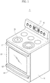
- FIG. 1 illustrates an exterior appearance of a gas oven in accordance with an exemplary embodiment of the present disclosure
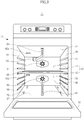
- FIG. 2 illustrates an inside of a gas oven
- FIG. 3 is a schematic side cross-sectional view of a gas oven .
- a gas oven 1 includes a body 10, a cooking cavity 40 provided at inside the body 10 to accommodate a food substance therein, a plurality of burners 61 and 62 to generate heat by combusting gas, and a plurality of convection fans 51 and 52 to convect air of the cooking cavity 40.
- the cooking cavity 40 may be formed in the approximate shape of a box by an upper portion wall 31, a lower portion wall 32, a left side wall 33, a right side wall 34, and a rear wall 35, and may be provided with a front surface thereof open for the input/output of a cooking substance.
- the open front surface of the cooking cavity 40 may be open and closed by a door 20 hingedly coupled to the body 10 so as to be rotatable in an upper and lower side direction.
- a handle 21 may be provided at the door 20, a handle 21 may be provided.
- a cook top unit 13 at which a container filled with a food substance may be placed and heat is applied to the container, a display 11 to display various operational information of the gas oven 1, and a manipulation unit 12 capable of manipulating the operation of the gas oven 1 may be provided.
- the plurality of supporters 36 may be protrudedly provided from the left side wall 33 and the right side wall 34.
- a divider 43 capable of dividing the cooking cavity 40 is detachably mounted.
- the divider 43 may be horizontally mounted at the cooking cavity 40 to divide the cooking cavity 40 into an individual cooking cavity at an upper portion 41 and an individual cooking cavity at a lower portion 42.
- the individual cooking cavity at an upper portion 41 and the individual cooking cavity at a lower portion 42 are hereinafter referred to as a first individual cooking cavity 41 and a second individual cooking cavity 42, respectively.
- the first individual cooking cavity 41 and the second individual cooking cavity 42 are not necessarily needed to be the same size, and the size of the first individual cooking cavity 41 and the second individual cooking cavity 42 each may be different.
- the divider 43 is provided with insulation material, and insulates the first individual cooking cavity 41 from the second individual cooking cavity 42.
- the burner 61 provided at the first individual cooking cavity 41 is referred to as the first burner 61
- the burner 62 provided at the second individual cooking cavity 42 is referred to as the second burner 62.
- the first burner 61 may radiate heat to the first individual cooking cavity 41
- the second burner 62 may radiate heat to the second individual cooking cavity 42.
- a convection fan 51 of the plurality of convection fans 51 and 52 may be provided, and at the second individual cooking cavity 42, another convection fan 52 of the plurality of convection fans 51 and 52 may be provided.
- the convection fan 51 may convect the air of the first individual cooking cavity 41
- the convection fan 52 may convect the air of the second individual cooking cavity 42.
- a storage compartment 90 configured to store cookware may be provided.
- the storage compartment 90 may be open and closed by a drawer 91 configured to be inserted into and withdrawn from in a sliding manner.
- a handle 92 may be provided at the drawer 91.
- the gas oven 1 may be provided with a main air supplying passage 70 configured to provide the second individual cooking cavity 42 with a passage outside the body 10 to supply air to the second individual cooking cavity 42.
- a main air supplying passage 70 configured to provide the second individual cooking cavity 42 with a passage outside the body 10 to supply air to the second individual cooking cavity 42.
- gas, air and arc are needed, and through the main air supplying passage 70, air for combustion may be supplied to the second individual cooking cavity 42.
- the main air supplying passage 70 may be formed by a penetrating hole 70a passing through the lower portion wall 32, the storage compartment 90, and a through hole 70b being formed through the rear wall 35.
- the main air supplying passage 70 in a case when the divider 43 is mounted at the cooking cavity 40, may be able to supply air to the second individual cooking cavity 42, and in a case when the divider 43 is separated from the cooking cavity 40, the main air supplying passage 70 may be able to supply air to the entire area of the cooking cavity 40.
- the gas oven 1 is provided with a main air discharging passage 80 configured to communicate the first individual cooking cavity 41 with an outside the body 10 to discharge waste gas of the first individual cooking cavity 41.
- the waste gas may be referred to as the combustion gas that is generated after combustion. In a case when gas is completely combusted, carbon monoxide and vapor are generated. In a case when gas is not completely combusted, carbon monoxide, hydrogen and sulfur may be generated. When the waste gas as such is remained without being discharged, incomplete combustion is generated at the burner, and thus waste gas is needed to be discharged to an outside.
- the main air discharging passage 80 may be formed by an air discharging hole 80a passing through the upper portion wall 31 and an air discharging duct 80b communicating the air discharging hole 80a with an outside the body 10.
- the main air discharging passage 80 in a case when the divider 43 is mounted at the cooking cavity 40, is able to discharge waste gas of the first individual cooking cavity 41, and in a case when the divider 43 is separated from the cooking cavity 40, the main air discharging passage 80 may be able to discharge waste gas of the entire area of the cooking cavity 40.
- the gas oven 1 may be provided with an auxiliary air supplying device 100 configured to supply air to the first individual cooking cavity 41 naturally or forcedly.
- the auxiliary air supplying device 100 may be configured to supply air to the first individual cooking cavity 41 in a case when the divider 43 is mounted at the cooking cavity 40.
- the air being supplied to the second individual cooking cavity 42 through the main air supplying passage 70 may be blocked from being moved to the first individual cooking cavity 41.
- the auxiliary air supplying device 100 in a case when the first burner 61 and the second burner 62 are simultaneously operated, supplies air to the first individual cooking cavity 41.
- the auxiliary air supplying device 100 may forcedly supply air to the first individual cooking cavity 41, and in an aspect as such, the auxiliary air supplying device 100 may be referred to as a forced air supplying device 100.
- the auxiliary air supplying device 100 may include an auxiliary air supplying passage 110 configured to connect the first individual cooking cavity 41 with an outside the body 10, an air supplying damper 120 to open/close the auxiliary air supplying passage 110, and an air supplying fan 130 configured to forcedly move the air at an outside the cooking cavity 40 to the first individual cooking cavity 41 through the auxiliary air supplying passage 110.
- the air supplying fan 130 by forcedly sucking the air of an outside the cooking cavity 40, moves the air to inside the first burner 61 or to the surroundings of the first burner 61.
- the air supplying fan 130 may forcedly move air so as to have the first burner 61 and the second burner 62 operate in a simultaneous manner.
- the waste gas generated from the second burner 62 may ascend to move to the surroundings of the first burner 61, and by the waste gas introduced to the surroundings of the first burner 61, incomplete combustion may occur at the first burner 61. That is, the supply of the second air to the first burner 61 may become difficult due to the waste gas of the second burner 62.
- the waste gas of the second burner 62 may be introduced to the surroundings of the first burner 61 through a gap between the divider 43 and the door 20 and a gap between the divider 43 and the both side walls 33 and 34 (see, for example, FIG. 2 ), as well as through a gap between the divider 43 and the rear wall 35.
- the air supplying damper 120 needs to shut off the auxiliary air supplying passage 110. This is because, in the case as such, the supplying of air to the cooking cavity 40 takes place through the main air supplying passage 70 and the discharging of the waste gas of the cooking cavity 40 may take place through the main air discharging passage 80.
- the auxiliary air supplying passage 110 is open, a high-temperature waste gas of the cooking cavity 40 may be excessively discharged.
- the air supplying damper 120 may need to shut off the auxiliary air supplying passage 110.
- the gas oven 1 is provided with an auxiliary air discharging device 200 configured to discharge waste gas of the second individual cooking cavity 42.
- the auxiliary air discharging device 200 is configured to discharge waste gas of the second individual cooking cavity 42 when the divider 43 is mounted at the cooking cavity 40.
- the waste gas of the second individual cooking cavity 42 may not be able to be discharged through the main air discharging passage 80.
- the auxiliary air discharging device 200 may include an auxiliary air discharging passage 210 configured to connect the second individual cooking cavity 42 to outside the cooking cavity 40, and an air discharging damper 220 configured to open and close the auxiliary air discharging passage 210.
- the auxiliary air discharging passage 210 may join the main air discharging passage 80 while being vertically extended at a space between the rear wall 35 of the cooking cavity 40 and an outside case 14 of the body 10.
- the auxiliary air discharging passage 210 may be independently extended to an outside the body 10 without joining the main air discharging passage 80.
- the waste gas of the second individual cooking cavity 42 may be discharged outside of the body 10.
- the air discharging damper 220 may need to shut off the auxiliary air discharging passage 210.
- the waste gas of the cooking cavity 40 may be discharged through the main air discharging passage 80, and when the auxiliary air discharging passage 210 is open, the high-temperature waste gas of the cooking cavity 40 may be excessively discharged through the auxiliary air discharging passage 210.
- the air discharging damper 220 may need to shut off the auxiliary air discharging passage 210.
- FIG. 4 illustrates a gas supplying passage of the gas oven
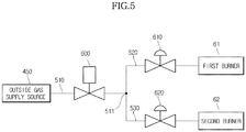
- FIG. 5 illustrates a flow of the gas supply of the gas oven
- FIG. 7 illustrates a difference in the measured temperature of the gas oven according to time.
- FIGS. 4 and 5 a gas supplying passage and a valve system of the gas oven 1 of an exemplary embodiment are described.
- the gas supplying passage includes a common passage 510 connected to an outside gas supply source 450, a first passage 520 connected to the first burner 61 while being diverged from the common passage 510, a second passage 530 connected to the second burner 62 while being diverged from the common passage 510, a cook top gas supplying passage 740 (see, for example, FIG. 4 ) connected to the cook top unit 13 while being diverged from the common passage 510.
- an outside gas connecting hole 750 to which a hose being connected to the outside gas supply source 450 may be connected, may be provided.
- an ON/OFF valve 600 configured to allow or shut off the supply of gas
- a first flow rate modulating valve 610 and a second flow rate modulating valve 620 each capable of modulating an opening degree thereof, are provided at the first passage 520 and the second passage 530, respectively.
- the modulating of the opening degree may be referred to as the modulating of the flow rate of gas through the change of the cross-sectional area of a flow passage.
- the flow rate modulating valve may be able to perform not only the ON/OFF controlling as the above but also modulate the flow of gas through the change of the cross-sectional area of the flow.
- the flow rate modulating valve may be able to perform the controlling of the flow rate more immediately and easily than the ON/OFF valve.
- the ON/OFF valve 600, the first flow rate modulating valve 610, and the second flow rate modulating valve 620 may be controlled independent of one another.
- the ON/OFF valve 600, the first flow rate modulating valve 610, and the second flow rate modulating valve 620 may be solenoid valves.
- the first flow rate modulating valve 610 and the ON/OFF valve 600 may be connected to each other in series.
- the supply of gas to the first individual cooking cavity 41 needs to be shut off, by shutting off the ON/OFF valve 600 and the first flow rate modulating valve 610 simultaneously, the risk of an accident as a result of a malfunction of the valve may be effectively prevented.
- the second flow rate modulating valve 620 and the ON/OFF valve 600 may be connected to each other in series, and thus, in a case when the supply of gas to the second individual cooking cavity 42 needs to be shut off, by shutting off the ON/OFF valve 600 and the second flow rate modulating valve 620 simultaneously, the risk of an accident as a result of a malfunction of the valve may be effectively prevented.
- the divider 43 may be mounted thereto or separated therefrom, and thus depending on whether or not the divider 43 is mounted, the cooking area may be changed.
- the cooking area is decreased in individual cooking cavities 41 and 42, in a case when the divider 43 is mounted as compared to the cooking cavity 40 in a case when the divider 43 is not mounted.
- a phenomenon that a food substance is carbonized may occur when a same amount of gas is supplied.
- the gas oven 1 in accordance with an embodiment of the present disclosure by using the flow rate modulating valves 610 and 620 may effectively respond to the change of a cooking area.
- the gas oven 1 in accordance with an embodiment of the present disclosure has a first mode during which the divider 43 is mounted and only the first burner 61 is operated, a second mode during which the divider 43 is mounted and only the second burner 62 is operated, a third mode during which the divider 43 is mounted and the first burner 61 and the second burner 62 are simultaneously operated, a fourth mode during which the divider 43 is separated and only the first burner 61 is operated, a fifth mode during which the divider 43 is separated and only the second burner 62 is operated, and a sixth mode during which the divider 43 is separated and the first burner 61 and the second burner 62 are simultaneously operated, and if the first flow rate modulating valve 610 or the second flow rate modulating valve 620 is open/closed at a maximum opening degree in the fourth mode and the fifth mode, the first flow rate modulating valve 610 and the second flow rate modulating valve 620 each may be open/closed at an opening degree smaller than the maximum opening degree in the first mode, the second mode, the third mode,
- the amount of the gas being supplied to each burner during the first mode, the second mode, the third mode and the sixth mode may be less than the amount of the gas being supplied during the fourth mode and the fifth mode.
- the first flow rate modulating valve 610 and the second flow rate modulating valve 620 each are open at an opening degree less than the maximum opening degree at the time of an ignition of the burners 61 and 62, and thus an occurrence of an explosive ignition at the time of a re-ignition after a failure of the ignition may be prevented.
- the gas oven 1 in accordance with an embodiment of the present disclosure may be able to reduce a value of a difference "D" between a maximum temperature measured and a minimum temperature measured.
- FIG. 6 illustrates a flow of the supply of gas of a gas oven in accordance with an exemplary embodiment of the present disclosure.
- the gas supplying passage and the valve system of the gas oven in accordance with the an exemplary embodiment of the present disclosure is described.
- the gas supplying passage includes a common passage 710 connected to the outside gas supply source 450, a first passage 720 connected to the first burner 61 while being diverged from the common passage 710, and a second passage 730 connected to the second burner 62 while being diverged from the common passage 710.
- a first ON/OFF valve 810 configured to allow or shut off the supply of gas, as well as a first flow rate modulating valve 820, capable of modulating an opening degree thereof, are provided, and at the second passage 730, a second ON/OFF valve 830, configured to allow or shut off the supply of gas, as well as a second flow rate modulating valve 840 capable of modulating an opening degree thereof.
- the first ON/OFF valve 810, the first flow rate modulating valve 820, the second ON/OFF valve 830, and the second flow rate modulating valve 840 may be controlled independent of one another.
- the first ON/OFF valve 810, the first flow rate modulating valve 820, the second ON/OFF valve 830, and the second flow rate modulating valve 840 may be solenoid valves.
- the first ON/OFF valve 810 and the first flow rate modulating valve 820 may be connected to each other in series, and the second ON/OFF valve 830 and the second flow rate modulating valve 840 may be connected to each other in series.
- the risk of an accident which may be a result of a malfunction of a valve is effectively prevented by shutting off the supply of gas in a dual manner in a case when the supply of gas needs to be shut off.
- a phenomenon of a carbonization and undercooking of a food substance is prevented by a changing the opening degree of the first flow rate modulating valve 820 and the second flow rate modulating valve 840 according to the usage mode of the gas oven 1.
- the prevention of the explosive ignition at the time of an ignition, as well as the reducing of the difference between the maximum temperature measured and the minimum temperature measured, is similar as the first embodiment of the present disclosure.
- FIG. 8 illustrates a flow rate modulating valve of the gas oven.
- the flow rate modulating valve 610 includes a coil 920 wound in the form of a cylinder and configured to generate a magnetic field when applied with a current, a plunger 930 configured to move downward by the magnetic field, a valve body 916 configured to move downward by being pressed by the plunger 930 so as to modulate an opening degree of a connecting hole 915 that connects an inlet 911 to an outlet 912 according to the amount of movement thereof, and a restoring spring 918 configured to elastically support the valve body 916 to restore the position of the valve body 916 when the current applied to the coil 920 is removed.
- the coil 920 may be wound around a bobbin 921 having the shape of a cylinder, and at the upper side and the lower side of the bobbin 921, a yoke 923 and a core 922 each forming a magnetic path may be respectively provided.
- a current is applied to the coil 920, the core 922 is magnetized to pull the plunger 930 downward.
- the plunger 930 may be accommodated inside a plunger housing 931 configured to guide the movement of the plunger 930.
- the valve body 916 may be supported while insertedly coupled to a diaphragm 940.
- the diaphragm 940 may be provided with an outer end portion thereof insertedly coupled between the core 922 and the valve housing 910.
- the diaphragm 940 may isolate a solenoid unit at an upper side from a valve unit at a lower side.
- the diaphragm 940 may be supported between an upper portion supporting panel 941 and a lower portion supporting panel 942.
- the valve housing 910 includes an inlet chamber 913 connected to the inlet 911 and an outlet chamber 914 connected to the outlet 912, and the inlet chamber 913 and the outlet chamber 914 may be connected to each other through the connecting hole 915.
- the connecting hole 915 is formed in a circular shape having a predetermined cross section, and the cross section of the connecting hole 915, that is, an opening degree, may be modulated according to the position of the valve body 916.
- a packing 917 having the shape of a cone may be provided at a lower end portion of the valve body 916.
- the flow rate modulating valve 610 includes an adjustment unit 950 configured to adjust the change of the opening degree of the connecting hole 915 according to the moving distance of the plunger 930 by adjusting the initial position of the plunger 930.
- the adjustment unit 950 may include an adjustment bolt 951, an adjustment guide 952 to which the adjustment bolt 951 is coupled, and a buffer spring 953 configured to change the initial position of the plunger 930 according to the amount of coupling of the adjustment bolt 951.
- the buffer spring 953 may be supported by an upper portion surface of the plunger 930 and a supporting cap 955 inserted into the adjustment bolt 951.
- a coupling nut 954 may be coupled to the adjustment bolt 951 to fix the adjustment bolt 951 after completing the adjustment of the adjustment bolt 951.
- a user by adjusting the position of the plunger 930 by use of the adjustment bolt 951 during an initial stage, may be able to adjust the moving distance of the plunger 930, that is, the change of the opening degree according to the amount of current that is applied to the coil 920.
- the amount of gas supplied to a burner may be reduced, so that the carbonization of a cooking substance may be prevented.
- the supply of gas is shut off in a way that an ON/OFF valve and a flow rate modulating valve that are connected in series with each other are simultaneously shut off, and thus the safety thereof may be enhanced.
- the difference in the measured temperature of the cooking cavity may be reduced.
- the flow rate modulating valve may be provided with a modulation unit capable of modulating the initial position of a plunger, and thus the change of an opening degree may be modulated according to the moving distance of the plunger.
Landscapes
- Engineering & Computer Science (AREA)
- General Engineering & Computer Science (AREA)
- Mechanical Engineering (AREA)
- Chemical & Material Sciences (AREA)
- Combustion & Propulsion (AREA)
- Food Science & Technology (AREA)
- Feeding And Controlling Fuel (AREA)
- Cookers (AREA)
- Baking, Grill, Roasting (AREA)
Description
- The present invention relates to a gas oven configured to use a cooking cavity divided into a plurality of individual cooking cavities by use of a divider. A gas oven is an appliance, provided with a cooking cavity in which a food substance is accommodated, a burner configured to generate heat by combusting gas and air, a gas supplying passage configured to supply gas to the burner, and an ignition device configured to generate an arc, to cook the food substance accommodated in the cooking cavity by applying heat at high temperature. At the gas supplying passage, a valve configured to shut off and allow the supply of gas to a burner may be provided. In general, one of a Bi-metal ON/OFF valve and a solenoid ON/OFF valve may be provided. With a Bi-metal ON/OFF valve, since the Bi-metal may be needed to be sufficiently heated or cooled for the valve to open or close, the Bi-metal ON/OFF valve may be provided with an increased safety mechanism compared to a solenoid ON/OFF valve, while having relatively lower reactivity. The solenoid ON/OFF valve may be immediately open and/or shut off depending on whether a current is applied thereto. The solenoid ON/OFF valve may have superior reactivity when compared to the Bi-metal ON/OFF valve, while having relatively less safety. A gas supplying passage, whether it is provided with the Bi-metal ON/OFF valve or the solenoid ON/OFF valve, may only be open or shut off and difficult to change a cross section thereof. Thus, in a case when a divider is mounted, for example, a cooking capacity and a cooking area is changed, the controlling of the amount of gas may be difficult to be properly adjusted.
-
EP 1994827 relates to a baking oven. -
EP 0462583 relates to a membrane controlled gas pressure regulator. -
FR 2629182 -
GB 2321962 -
GB 2093984 -
EP 1657493 relates to an electric oven with a partition plate. -
US 2007/257020 relates to a cooking apparatus. -
GB 2289329 -
US 2010/0001087 relates to a variable output heating control system. -
US2003010221 relates to a steam oven with a removable divider. -
DE102007039379 relates to an oven with discharge passages and which can generate two cooking environments without a divider. - It is an aspect of the present disclosure to provide a gas oven provided with a valve system capable of properly responding to the change of a cooking area and reducing the difference in measured temperature while having enhanced safety. Additional aspects of the disclosure will be set forth in part in the description which follows. According to an aspect of the present invention, a gas oven is provided according to
claim 1. - In accordance with an aspect of the present disclosure, a gas oven includes a body, a cooking cavity, a divider, a first burner, a second burner, a supply passage comprising common, first and second passages, a main discharging passage, an auxiliary discharging passage, a first flow rate modulating valve and a second flow rate modulating valve, and either an ON/OFF valve provided at the common passage, or a first ON/OFF valve provided at the first passage and a second ON/OFF valve provided at the second passage. The cooking cavity is formed inside the body. The divider is detachably mounted at the cooking cavity to divide the cooking cavity into a first individual cooking cavity at an upper portion of the body and a second individual cooking cavity at a lower portion of the body. The first burner is provided at the first individual cooking cavity.
- The second burner is provided at the second individual cooking cavity. The supply passage is configured to supply gas to the first burner and the second burner from an outside gas supply source, the supply passage including a common passage connected to the outside gas supply source, and a first passage and a second passage that are diverged from the common passage to be connected to the first burner and to the second burner, respectively. The main discharging passage is for discharging a waste gas from at least the first individual cooking cavity. The auxiliary discharging passage is for discharging the waste gas from the second individual cooking cavity when the divider is mounted. The first flow rate modulating valve is provided at the first passage and capable of modulating an opening degree thereof. The second flow rate modulating valve is provided at the second passage and capable of modulating an opening degree thereof.
- Each of the ON/Off valve, the first flow rate modulating valve, and the second flow rate modulating valve may be a solenoid valve.
- The gas oven may have a first mode during which the divider is mounted and only the first burner is operated, a second mode during which the divider is mounted and only the second burner is operated, a third mode during which the divider is mounted and the first burner and the second burner are simultaneously operated, a fourth mode during which the divider is separated and only the first burner is operated, a fifth mode during which the divider is separated and only the second burner is operated, and a sixth mode during which the divider is separated and the first burner and the second burner are simultaneously operated.
- In the fourth mode and the fifth mode, the first flow rate modulating valve or the second flow rate modulating valve may be open/closed at a maximum opening degree, and in the first mode, the second mode, the third mode, and the sixth mode, the first flow rate modulating valve and the second flow rate modulating valve each may be open/closed at an opening degree smaller than the maximum opening degree.
- During ignition of the first burner or the second burner, the first flow rate modulating valve or the second flow rate modulating valve may be open at an opening degree smaller than a maximum opening degree to prevent an explosive ignition.
- After a temperature measured at the first individual cooking cavity or the second individual cooking cavity exceeds a predetermined temperature, an opening degree of the first flow rate modulating valve or the second flow rate modulating valve may be gradually shut off.
- Each of the first flow rate modulating valve and the second flow rate modulating valve may include a coil, a plunger, a valve body, a restoring spring, and an adjustment unit. The coil may be wound in a form of a cylinder and configured to generate a magnetic field when applied with a current. The plunger may be configured to move downward by the magnetic field. The valve body may be configured to move downward while being pressed by the plunger to adjust an opening degree of a connecting hole that connects an inlet to an outlet according to an amount of movement thereof. The restoring spring may be configured to elastically support the valve body to restore a position of the valve body when the current applied to the coil is removed. The adjustment unit may be capable of adjusting a change of the opening degree according to a moving distance of the plunger by adjusting an initial position of the plunger.
- The adjustment unit may include an adjustment bolt, an adjustment guide to which the adjustment bolt is coupled, and a buffer spring provided between the adjustment bolt and the plunger to change the initial position of the plunger according to an amount of the coupling of the adjustment bolt.
- Each of the first ON/Off valve, the first flow rate modulating value, the second ON/OFF valve and the second flow rate modulating valve may be a solenoid valve.
- In accordance with an embodiment, a gas oven includes a body, a cooking cavity, a burner, a supply passage, an ON/OFF valve, and a flow rate modulating valve. The cooking cavity may be formed at inside the body. The burner may be provided at the cooking cavity. The supply passage may be configured to supply gas from an outside gas supply source to the burner. The ON/OFF valve may be provided at the supply passage and configured to open/shut off the supply passage. The flow rate modulating valve may be provided at the supply valve so as to be connected in series with the ON/OFF valve and capable of modulating an opening degree thereof.
- Each of the ON/OFF valve and the flow rate modulating valve may be a solenoid valve.
- During ignition of the burner, the flow rate modulating valve may be open at an opening degree smaller than a maximum opening degree to prevent explosive ignition.
- After a temperature measured at the cooking cavity exceeds a predetermined temperature, the opening degree of the flow rate modulating valve may be gradually shut off.
- In accordance with an embodiment, a flow rate modulating valve includes a coil, a plunger, a valve body, a restoring spring, and an adjustment unit. The coil may be wound in a form of a cylinder and configured to generate a magnetic field when applied with a current. The plunger may be configured to move downward by the magnetic field. The valve body may be configured to move downward while being pressed by the plunger and configured to modulate an opening degree of a connecting hole that connects an inlet to an outlet according to an amount of movement thereof. The restoring spring may be configured to elastically support the valve body to restore a position of the valve body when the current applied to the coil is removed. The adjustment unit may be capable of adjusting a change of the opening degree according to a moving distance of the plunger by adjusting an initial position of the plunger.
- The adjustment unit may include an adjustment bolt, an adjustment guide to which the adjustment bolt is coupled, and a buffer spring provided between the adjustment bolt and the plunger to change an initial position of the plunger according to an amount of the coupling of the adjustment bolt.
- These and/or other aspects of the disclosure will become apparent and more readily appreciated from the following description of the embodiments, taken in conjunction with the accompanying drawings of which:
-
FIG. 1 illustrates an exterior appearance of a gas oven in accordance with an embodiment of the present disclosure. -
FIG. 2 illustrates an inside of an exemplary gas oven. -
FIG. 3 is a schematic side cross-sectional view of an exemplary gas oven. -
FIG. 4 illustrates an exemplary gas supplying passage of a gas oven. -
FIG. 5 illustrates an exemplary flow of a gas supply of a gas oven. -
FIG. 6 illustrates a flow of the gas supply of a gas oven in accordance with an exemplary embodiment of the present disclosure. -
FIG. 7 illustrates an exemplary difference in a measured temperature of the gas oven according to time. -
FIG. 8 illustrates an exemplary flow rate modulating valve of a gas oven . - Reference will now be made in detail to the embodiments of the present disclosure, examples of which are illustrated in the accompanying drawings, wherein like reference numerals refer to like elements throughout.
-
FIG. 1 illustrates an exterior appearance of a gas oven in accordance with an exemplary embodiment of the present disclosure,FIG. 2 illustrates an inside of a gas oven, andFIG. 3 is a schematic side cross-sectional view of a gas oven . - Referring to
FIGS. 1 to 3 , agas oven 1 includes abody 10, acooking cavity 40 provided at inside thebody 10 to accommodate a food substance therein, a plurality ofburners convection fans cooking cavity 40. - The
cooking cavity 40 may be formed in the approximate shape of a box by anupper portion wall 31, alower portion wall 32, aleft side wall 33, aright side wall 34, and arear wall 35, and may be provided with a front surface thereof open for the input/output of a cooking substance. The open front surface of thecooking cavity 40 may be open and closed by adoor 20 hingedly coupled to thebody 10 so as to be rotatable in an upper and lower side direction. At thedoor 20, ahandle 21 may be provided. - At an upper end of the
body 10, acook top unit 13 at which a container filled with a food substance may be placed and heat is applied to the container, adisplay 11 to display various operational information of thegas oven 1, and amanipulation unit 12 capable of manipulating the operation of thegas oven 1 may be provided. - A plurality of
supporters 36 to mount a rack (not shown), at which a food substance may be placed, thereon is provided at inside thecooking cavity 40. The plurality ofsupporters 36 may be protrudedly provided from theleft side wall 33 and theright side wall 34. - At the plurality of
supporters 36, adivider 43 capable of dividing thecooking cavity 40 is detachably mounted. Thedivider 43 may be horizontally mounted at thecooking cavity 40 to divide thecooking cavity 40 into an individual cooking cavity at anupper portion 41 and an individual cooking cavity at alower portion 42. - The individual cooking cavity at an
upper portion 41 and the individual cooking cavity at alower portion 42 are hereinafter referred to as a firstindividual cooking cavity 41 and a secondindividual cooking cavity 42, respectively. The firstindividual cooking cavity 41 and the secondindividual cooking cavity 42 are not necessarily needed to be the same size, and the size of the firstindividual cooking cavity 41 and the secondindividual cooking cavity 42 each may be different. Thedivider 43 is provided with insulation material, and insulates the firstindividual cooking cavity 41 from the secondindividual cooking cavity 42. - In the first
individual cooking cavity 41, one of the plurality ofburners individual cooking cavity 42, another one of the plurality ofburners burner 61 provided at the firstindividual cooking cavity 41 is referred to as thefirst burner 61, and theburner 62 provided at the secondindividual cooking cavity 42 is referred to as thesecond burner 62. Thus, thefirst burner 61 may radiate heat to the firstindividual cooking cavity 41, and thesecond burner 62 may radiate heat to the secondindividual cooking cavity 42. - In the first
individual cooking cavity 41, aconvection fan 51 of the plurality ofconvection fans individual cooking cavity 42, anotherconvection fan 52 of the plurality ofconvection fans convection fan 51 may convect the air of the firstindividual cooking cavity 41, and theconvection fan 52 may convect the air of the secondindividual cooking cavity 42. - At a lower side of the
cooking cavity 40, astorage compartment 90 configured to store cookware may be provided. Thestorage compartment 90 may be open and closed by adrawer 91 configured to be inserted into and withdrawn from in a sliding manner. At thedrawer 91, ahandle 92 may be provided. - The
gas oven 1 may be provided with a mainair supplying passage 70 configured to provide the secondindividual cooking cavity 42 with a passage outside thebody 10 to supply air to the secondindividual cooking cavity 42. For combustion to take place, gas, air and arc are needed, and through the mainair supplying passage 70, air for combustion may be supplied to the secondindividual cooking cavity 42. The mainair supplying passage 70 may be formed by a penetratinghole 70a passing through thelower portion wall 32, thestorage compartment 90, and a throughhole 70b being formed through therear wall 35. - The main
air supplying passage 70, in a case when thedivider 43 is mounted at thecooking cavity 40, may be able to supply air to the secondindividual cooking cavity 42, and in a case when thedivider 43 is separated from thecooking cavity 40, the mainair supplying passage 70 may be able to supply air to the entire area of thecooking cavity 40. - The
gas oven 1 is provided with a mainair discharging passage 80 configured to communicate the firstindividual cooking cavity 41 with an outside thebody 10 to discharge waste gas of the firstindividual cooking cavity 41. The waste gas may be referred to as the combustion gas that is generated after combustion. In a case when gas is completely combusted, carbon monoxide and vapor are generated. In a case when gas is not completely combusted, carbon monoxide, hydrogen and sulfur may be generated. When the waste gas as such is remained without being discharged, incomplete combustion is generated at the burner, and thus waste gas is needed to be discharged to an outside. - The main
air discharging passage 80 may be formed by anair discharging hole 80a passing through theupper portion wall 31 and anair discharging duct 80b communicating theair discharging hole 80a with an outside thebody 10. - The main
air discharging passage 80, in a case when thedivider 43 is mounted at thecooking cavity 40, is able to discharge waste gas of the firstindividual cooking cavity 41, and in a case when thedivider 43 is separated from thecooking cavity 40, the mainair discharging passage 80 may be able to discharge waste gas of the entire area of thecooking cavity 40. - The
gas oven 1 may be provided with an auxiliaryair supplying device 100 configured to supply air to the firstindividual cooking cavity 41 naturally or forcedly. The auxiliaryair supplying device 100 may be configured to supply air to the firstindividual cooking cavity 41 in a case when thedivider 43 is mounted at thecooking cavity 40. - In a case when the
divider 43 is mounted at thecooking cavity 40, the air being supplied to the secondindividual cooking cavity 42 through the mainair supplying passage 70 may be blocked from being moved to the firstindividual cooking cavity 41. - Furthermore, the auxiliary
air supplying device 100, in a case when thefirst burner 61 and thesecond burner 62 are simultaneously operated, supplies air to the firstindividual cooking cavity 41. The auxiliaryair supplying device 100 may forcedly supply air to the firstindividual cooking cavity 41, and in an aspect as such, the auxiliaryair supplying device 100 may be referred to as a forcedair supplying device 100. - The auxiliary
air supplying device 100 may include an auxiliaryair supplying passage 110 configured to connect the firstindividual cooking cavity 41 with an outside thebody 10, anair supplying damper 120 to open/close the auxiliaryair supplying passage 110, and anair supplying fan 130 configured to forcedly move the air at an outside thecooking cavity 40 to the firstindividual cooking cavity 41 through the auxiliaryair supplying passage 110. - The
air supplying fan 130, by forcedly sucking the air of an outside thecooking cavity 40, moves the air to inside thefirst burner 61 or to the surroundings of thefirst burner 61. Theair supplying fan 130 may forcedly move air so as to have thefirst burner 61 and thesecond burner 62 operate in a simultaneous manner. - Since, in a case when the
first burner 61 and thesecond burner 62 simultaneously operate, the waste gas generated from thesecond burner 62 may ascend to move to the surroundings of thefirst burner 61, and by the waste gas introduced to the surroundings of thefirst burner 61, incomplete combustion may occur at thefirst burner 61. That is, the supply of the second air to thefirst burner 61 may become difficult due to the waste gas of thesecond burner 62. - When the
divider 43 is separated from thecooking cavity 40, in a case when thedivider 43 is mounted at thecooking cavity 40, a forced supply of air may be needed by theair supplying fan 130. When thedivider 43 is mounted at thecooking cavity 40, the waste gas of thesecond burner 62 may be introduced to the surroundings of thefirst burner 61 through a gap between thedivider 43 and thedoor 20 and a gap between thedivider 43 and the bothside walls 33 and 34 (see, for example,FIG. 2 ), as well as through a gap between thedivider 43 and therear wall 35. - When the
divider 43 is separated from thecooking cavity 40 and when one of thefirst burner 61 and thesecond burner 62 are operated, theair supplying damper 120 needs to shut off the auxiliaryair supplying passage 110. This is because, in the case as such, the supplying of air to thecooking cavity 40 takes place through the mainair supplying passage 70 and the discharging of the waste gas of thecooking cavity 40 may take place through the mainair discharging passage 80. When the auxiliaryair supplying passage 110 is open, a high-temperature waste gas of thecooking cavity 40 may be excessively discharged. - When the
gas oven 1 performs a self-cleaning at a high temperature, theair supplying damper 120 may need to shut off the auxiliaryair supplying passage 110. - The
gas oven 1 is provided with an auxiliaryair discharging device 200 configured to discharge waste gas of the secondindividual cooking cavity 42. The auxiliaryair discharging device 200 is configured to discharge waste gas of the secondindividual cooking cavity 42 when thedivider 43 is mounted at thecooking cavity 40. - When the
divider 43 is mounted at thecooking cavity 40, the waste gas of the secondindividual cooking cavity 42 may not be able to be discharged through the mainair discharging passage 80. - The auxiliary
air discharging device 200 may include an auxiliaryair discharging passage 210 configured to connect the secondindividual cooking cavity 42 to outside thecooking cavity 40, and anair discharging damper 220 configured to open and close the auxiliaryair discharging passage 210. - The auxiliary
air discharging passage 210 may join the mainair discharging passage 80 while being vertically extended at a space between therear wall 35 of thecooking cavity 40 and anoutside case 14 of thebody 10. The auxiliaryair discharging passage 210 may be independently extended to an outside thebody 10 without joining the mainair discharging passage 80. The waste gas of the secondindividual cooking cavity 42 may be discharged outside of thebody 10. - When the
divider 43 is separated from thecooking cavity 40, theair discharging damper 220 may need to shut off the auxiliaryair discharging passage 210. The waste gas of thecooking cavity 40 may be discharged through the mainair discharging passage 80, and when the auxiliaryair discharging passage 210 is open, the high-temperature waste gas of thecooking cavity 40 may be excessively discharged through the auxiliaryair discharging passage 210. - When the
gas oven 1 performs a self-cleaning at a high temperature, theair discharging damper 220 may need to shut off the auxiliaryair discharging passage 210. -
FIG. 4 illustrates a gas supplying passage of the gas oven,FIG. 5 illustrates a flow of the gas supply of the gas oven, andFIG. 7 illustrates a difference in the measured temperature of the gas oven according to time. - Referring to
FIGS. 4 and5 , a gas supplying passage and a valve system of thegas oven 1 of an exemplary embodiment are described. - The gas supplying passage includes a
common passage 510 connected to an outsidegas supply source 450, afirst passage 520 connected to thefirst burner 61 while being diverged from thecommon passage 510, asecond passage 530 connected to thesecond burner 62 while being diverged from thecommon passage 510, a cook top gas supplying passage 740 (see, for example,FIG. 4 ) connected to thecook top unit 13 while being diverged from thecommon passage 510. - At a rear of the
gas oven 1, an outsidegas connecting hole 750, to which a hose being connected to the outsidegas supply source 450 may be connected, may be provided. - At the
common passage 510, an ON/OFF valve 600 configured to allow or shut off the supply of gas is provided, and a first flowrate modulating valve 610 and a second flowrate modulating valve 620, each capable of modulating an opening degree thereof, are provided at thefirst passage 520 and thesecond passage 530, respectively. The modulating of the opening degree may be referred to as the modulating of the flow rate of gas through the change of the cross-sectional area of a flow passage. Thus, when compared to the ON/OFF valve capable of controlling the total flow during a certain time period through an ON/OFF control according to time, the flow rate modulating valve may be able to perform not only the ON/OFF controlling as the above but also modulate the flow of gas through the change of the cross-sectional area of the flow. Thus, the flow rate modulating valve may be able to perform the controlling of the flow rate more immediately and easily than the ON/OFF valve. - The ON/
OFF valve 600, the first flowrate modulating valve 610, and the second flowrate modulating valve 620 may be controlled independent of one another. The ON/OFF valve 600, the first flowrate modulating valve 610, and the second flowrate modulating valve 620 may be solenoid valves. - The first flow
rate modulating valve 610 and the ON/OFF valve 600 may be connected to each other in series. When the supply of gas to the firstindividual cooking cavity 41 needs to be shut off, by shutting off the ON/OFF valve 600 and the first flowrate modulating valve 610 simultaneously, the risk of an accident as a result of a malfunction of the valve may be effectively prevented. - The second flow
rate modulating valve 620 and the ON/OFF valve 600 may be connected to each other in series, and thus, in a case when the supply of gas to the secondindividual cooking cavity 42 needs to be shut off, by shutting off the ON/OFF valve 600 and the second flowrate modulating valve 620 simultaneously, the risk of an accident as a result of a malfunction of the valve may be effectively prevented. - With respect to a
gas oven 1 in accordance with an embodiment of the present disclosure, thedivider 43 may be mounted thereto or separated therefrom, and thus depending on whether or not thedivider 43 is mounted, the cooking area may be changed. - That is, the cooking area is decreased in
individual cooking cavities divider 43 is mounted as compared to thecooking cavity 40 in a case when thedivider 43 is not mounted. When the cooking area is decreased, a phenomenon that a food substance is carbonized may occur when a same amount of gas is supplied. - When the cooking area is increased, a phenomenon that a food substance is undercooked may occur. Thus, in the case when the cooking area is changed, to prevent the phenomenon of having a food substance carbonized or undercooked, the amount of gas being supplied needs to be modulated.
- The
gas oven 1 in accordance with an embodiment of the present disclosure, by using the flowrate modulating valves - As an example, the
gas oven 1 in accordance with an embodiment of the present disclosure has a first mode during which thedivider 43 is mounted and only thefirst burner 61 is operated, a second mode during which thedivider 43 is mounted and only thesecond burner 62 is operated, a third mode during which thedivider 43 is mounted and thefirst burner 61 and thesecond burner 62 are simultaneously operated, a fourth mode during which thedivider 43 is separated and only thefirst burner 61 is operated, a fifth mode during which thedivider 43 is separated and only thesecond burner 62 is operated, and a sixth mode during which thedivider 43 is separated and thefirst burner 61 and thesecond burner 62 are simultaneously operated, and if the first flowrate modulating valve 610 or the second flowrate modulating valve 620 is open/closed at a maximum opening degree in the fourth mode and the fifth mode, the first flowrate modulating valve 610 and the second flowrate modulating valve 620 each may be open/closed at an opening degree smaller than the maximum opening degree in the first mode, the second mode, the third mode, and the sixth mode . - Thus, the amount of the gas being supplied to each burner during the first mode, the second mode, the third mode and the sixth mode may be less than the amount of the gas being supplied during the fourth mode and the fifth mode.
- If a same amount of gas is supplied at all times at the time of ignition of the burners, in a case of a failure of the ignition, a large amount of gas may remain surrounding the burners, so that an explosive ignition may occur at the time of re-ignition.
- Thus, the first flow
rate modulating valve 610 and the second flowrate modulating valve 620 each are open at an opening degree less than the maximum opening degree at the time of an ignition of theburners - Referring to
FIG. 7 , when compared to the gas oven configured to modulate the amount of gas only by the ON/OFF controlling according to time under the condition that the ON/OFF cycle is not changed, thegas oven 1 in accordance with an embodiment of the present disclosure may be able to reduce a value of a difference "D" between a maximum temperature measured and a minimum temperature measured. - That is, when the measure temperature of the
cooking cavity 40 exceeds a predetermined temperature, by gradually shutting off the flowrate modulating valves cooking cavity 40 is decreased, and thus the difference "'D" between the maximum temperature measured and the minimum temperature measured may be reduced. -
FIG. 6 illustrates a flow of the supply of gas of a gas oven in accordance with an exemplary embodiment of the present disclosure. By referring toFIG. 6 , the gas supplying passage and the valve system of the gas oven in accordance with the an exemplary embodiment of the present disclosure is described. - The gas supplying passage includes a
common passage 710 connected to the outsidegas supply source 450, afirst passage 720 connected to thefirst burner 61 while being diverged from thecommon passage 710, and asecond passage 730 connected to thesecond burner 62 while being diverged from thecommon passage 710. - At the
first passage 720, a first ON/OFF valve 810, configured to allow or shut off the supply of gas, as well as a first flowrate modulating valve 820, capable of modulating an opening degree thereof, are provided, and at thesecond passage 730, a second ON/OFF valve 830, configured to allow or shut off the supply of gas, as well as a second flowrate modulating valve 840 capable of modulating an opening degree thereof. - The first ON/
OFF valve 810, the first flowrate modulating valve 820, the second ON/OFF valve 830, and the second flowrate modulating valve 840 may be controlled independent of one another. The first ON/OFF valve 810, the first flowrate modulating valve 820, the second ON/OFF valve 830, and the second flowrate modulating valve 840 may be solenoid valves. - The first ON/
OFF valve 810 and the first flowrate modulating valve 820 may be connected to each other in series, and the second ON/OFF valve 830 and the second flowrate modulating valve 840 may be connected to each other in series. Thus, the risk of an accident, which may be a result of a malfunction of a valve is effectively prevented by shutting off the supply of gas in a dual manner in a case when the supply of gas needs to be shut off. In addition, a phenomenon of a carbonization and undercooking of a food substance is prevented by a changing the opening degree of the first flowrate modulating valve 820 and the second flowrate modulating valve 840 according to the usage mode of thegas oven 1. - The prevention of the explosive ignition at the time of an ignition, as well as the reducing of the difference between the maximum temperature measured and the minimum temperature measured, is similar as the first embodiment of the present disclosure.
-
FIG. 8 illustrates a flow rate modulating valve of the gas oven. - Referring to
FIG. 8 , an exemplary flow rate modulating valve in accordance with the an embodiments of the present disclosure is described. The flowrate modulating valve 610 includes acoil 920 wound in the form of a cylinder and configured to generate a magnetic field when applied with a current, aplunger 930 configured to move downward by the magnetic field, avalve body 916 configured to move downward by being pressed by theplunger 930 so as to modulate an opening degree of a connectinghole 915 that connects aninlet 911 to anoutlet 912 according to the amount of movement thereof, and a restoringspring 918 configured to elastically support thevalve body 916 to restore the position of thevalve body 916 when the current applied to thecoil 920 is removed. - The
coil 920 may be wound around abobbin 921 having the shape of a cylinder, and at the upper side and the lower side of thebobbin 921, ayoke 923 and acore 922 each forming a magnetic path may be respectively provided. When a current is applied to thecoil 920, thecore 922 is magnetized to pull theplunger 930 downward. Theplunger 930 may be accommodated inside aplunger housing 931 configured to guide the movement of theplunger 930. - The
valve body 916 may be supported while insertedly coupled to adiaphragm 940. Thediaphragm 940 may be provided with an outer end portion thereof insertedly coupled between the core 922 and thevalve housing 910. Thediaphragm 940 may isolate a solenoid unit at an upper side from a valve unit at a lower side. Thediaphragm 940 may be supported between an upperportion supporting panel 941 and a lowerportion supporting panel 942. - The
valve housing 910 includes aninlet chamber 913 connected to theinlet 911 and anoutlet chamber 914 connected to theoutlet 912, and theinlet chamber 913 and theoutlet chamber 914 may be connected to each other through the connectinghole 915. - The connecting
hole 915 is formed in a circular shape having a predetermined cross section, and the cross section of the connectinghole 915, that is, an opening degree, may be modulated according to the position of thevalve body 916. For the above, at a lower end portion of thevalve body 916, a packing 917 having the shape of a cone may be provided. - The flow
rate modulating valve 610 includes anadjustment unit 950 configured to adjust the change of the opening degree of the connectinghole 915 according to the moving distance of theplunger 930 by adjusting the initial position of theplunger 930. - The
adjustment unit 950 may include anadjustment bolt 951, anadjustment guide 952 to which theadjustment bolt 951 is coupled, and a buffer spring 953 configured to change the initial position of theplunger 930 according to the amount of coupling of theadjustment bolt 951. - The buffer spring 953 may be supported by an upper portion surface of the
plunger 930 and a supportingcap 955 inserted into theadjustment bolt 951. Acoupling nut 954 may be coupled to theadjustment bolt 951 to fix theadjustment bolt 951 after completing the adjustment of theadjustment bolt 951. - Accordingly, a user, by adjusting the position of the
plunger 930 by use of theadjustment bolt 951 during an initial stage, may be able to adjust the moving distance of theplunger 930, that is, the change of the opening degree according to the amount of current that is applied to thecoil 920. - According to an exemplary embodiment, when dividing a cooking cavity of a gas oven into a plurality of individual cooking cavities by using a divider, the amount of gas supplied to a burner may be reduced, so that the carbonization of a cooking substance may be prevented.
- In a case when the gas supply to the burner is desired to be shut off, the supply of gas is shut off in a way that an ON/OFF valve and a flow rate modulating valve that are connected in series with each other are simultaneously shut off, and thus the safety thereof may be enhanced.
- By gradually shutting off the flow rate modulating valve after the measured temperature of the cooking cavity exceeds a predetermined temperature, the difference in the measured temperature of the cooking cavity may be reduced.
- The flow rate modulating valve may be provided with a modulation unit capable of modulating the initial position of a plunger, and thus the change of an opening degree may be modulated according to the moving distance of the plunger.
- Although a few embodiments of the present disclosure have been shown and described, it would be appreciated by those skilled in the art that changes may be made in these embodiments without departing from the principles of the invention, the scope of which is defined in the claims.
Claims (9)
- A gas oven (1), comprising:a body (10);a cooking cavity (40) formed inside the body;a divider (43) detachably mounted at the cooking cavity to divide the cooking cavity into a first individual cooking cavity (41) at an upper portion of the body and a second individual cooking cavity (42) at a lower portion of the body, wherein the divider is provided with insulation material and is configured to insulate the first individual cooking cavity from the second individual cooking cavity;a first burner (61) provided at the first individual cooking cavity;a second burner (62) provided at the second individual cooking cavity;a supply passage configured to supply gas to the first burner and the second burner from an outside gas supply source (450), the supply passage comprising a common passage (510) connected to the outside gas supply source, and a first passage (520) and a second passage (530) that are diverged from the common passage (510) to be connected to the first burner (61) and to the second burner (62), respectively;a main discharging passage (80) to discharge a waste gas from at least the first individual cooking cavity (41); a first flow rate modulating valve (610) provided at the first passage (520) and capable of modulating an opening degree thereof;a second flow rate modulating valve (620) provided at the second passage (530) and capable of modulating an opening degree thereof; and either an ON/OFF valve (600) provided at the common passage, ora first ON/OFF valve (810) provided at the first passage (520) and a second ON/OFF valve (830) provided at the second passage (530), characterised by an auxiliary discharging passage (200) to discharge the waste gas from the second individual cooking cavity (42) when the divider (43) is mounted.
- The gas oven (1) of claim 1, wherein:
each of the ON/OFF valve (600), the first flow rate modulating valve (610), and the second flow rate modulating valve (620) is a solenoid valve. - The gas oven (1) of claim 1 or 2, wherein:
the gas oven has a first mode during which the divider (43) is mounted and only the first burner (61) is arranged to be operated, a second mode during which the divider (43) is mounted and only the second burner (62) is arranged to be operated, a third mode during which the divider (43) is mounted and the first burner (61) and the second burner (62) are arranged to be simultaneously operated, a fourth mode during which the divider (43) is separated and only the first burner (61) is arranged to be operated, a fifth mode during which the divider (43) is separated and only the second burner (62) is arranged to be operated, and a sixth mode during which the divider (43) is separated and the first burner (61) and the second burner (62) are arranged to be simultaneously operated. - The gas oven (1) of claim 3, wherein:in the fourth mode and the fifth mode, the first flow rate modulating valve (610) or the second flow rate modulating valve (620) is arranged to be open/closed at a maximum opening degree, andin the first mode, the second mode, the third mode, and the sixth mode, the first flow rate modulating valve (610) and the second flow rate modulating valve (620) each are arranged to be open/closed at an opening degree smaller than the maximum opening degree.
- The gas oven (1) of any one of the preceding claims, wherein:
during ignition of the first burner (61) or the second burner (62), the first flow rate modulating valve (610) or the second flow rate modulating valve (620) is arranged to be open at an opening degree smaller than a maximum opening degree to prevent an explosive ignition. - The gas oven (1) of any one of the preceding claims, wherein:
after a temperature measured at the first individual cooking cavity (41) or the second individual cooking cavity (42) exceeds a predetermined temperature, an opening degree of the first flow rate modulating valve (610) or the second flow rate modulating valve (620) is arranged to be gradually shut off. - The gas oven (1) of any one of the preceding claims, wherein each of the first flow rate modulating valve (610) and the second flow rate modulating valve (620) comprises:a coil (920) wound in a form of a cylinder and configured to generate a magnetic field when applied with a current;a plunger (930) configured to move downward by the magnetic field;a valve body (916) configured to move downward while being pressed by the plunger (930) to adjust an opening degree of a connecting hole (915) that connects an inlet (911) to an outlet (912) according to an amount of movement thereof;a restoring spring (918) configured to elastically support the valve body (916) to restore a position of the valve body (916) when the current applied to the coil is removed; andan adjustment unit (950) capable of adjusting a change of the opening degree according to a moving distance of the plunger (930) by adjusting an initial position of the plunger (930).
- The gas oven (1) of claim 7, wherein:
the adjustment unit (950) comprises an adjustment bolt (951), an adjustment guide (952) to which the adjustment bolt (951) is coupled, and a buffer spring (953) provided in between the adjustment bolt (951) and the plunger (930) to change the initial position of the plunger (930) according to an amount of the coupling of the adjustment bolt (951). - The gas oven (1) of claim 1, wherein:
each of the first ON/OFF valve (810), the first flow rate modulating value (610), the second ON/OFF valve (830) and the second flow rate modulating valve (620) is a solenoid valve.
Applications Claiming Priority (1)
| Application Number | Priority Date | Filing Date | Title |
|---|---|---|---|
| KR1020120150581A KR101981670B1 (en) | 2012-12-21 | 2012-12-21 | Gas Oven |
Publications (3)
| Publication Number | Publication Date |
|---|---|
| EP2746668A2 EP2746668A2 (en) | 2014-06-25 |
| EP2746668A3 EP2746668A3 (en) | 2016-05-25 |
| EP2746668B1 true EP2746668B1 (en) | 2018-08-29 |
Family
ID=49886622
Family Applications (1)
| Application Number | Title | Priority Date | Filing Date |
|---|---|---|---|
| EP13197010.5A Active EP2746668B1 (en) | 2012-12-21 | 2013-12-12 | Gas oven |
Country Status (4)
| Country | Link |
|---|---|
| US (1) | US10203117B2 (en) |
| EP (1) | EP2746668B1 (en) |
| KR (1) | KR101981670B1 (en) |
| CN (1) | CN103876646A (en) |
Families Citing this family (25)
| Publication number | Priority date | Publication date | Assignee | Title |
|---|---|---|---|---|
| US20070006865A1 (en) | 2003-02-21 | 2007-01-11 | Wiker John H | Self-cleaning oven |
| US8087407B2 (en) | 2004-03-23 | 2012-01-03 | Middleby Corporation | Conveyor oven apparatus and method |
| US9585400B2 (en) | 2004-03-23 | 2017-03-07 | The Middleby Corporation | Conveyor oven apparatus and method |
| US8839714B2 (en) | 2009-08-28 | 2014-09-23 | The Middleby Corporation | Apparatus and method for controlling a conveyor oven |
| KR102318165B1 (en) * | 2015-01-05 | 2021-10-28 | 삼성전자주식회사 | Gas oven and controlling method thereof |
| CN105747894B (en) | 2015-01-05 | 2020-06-05 | 三星电子株式会社 | Gas oven and control method thereof |
| CN105402780B (en) * | 2015-12-28 | 2017-08-11 | 浙江博立灶具科技有限公司 | Cook a meal and use gas big kitchen range |
| AU2017286560B2 (en) | 2016-06-14 | 2023-03-09 | The Middleby Corporation | Convection conveyor oven manifold and damper system |
| JP6954818B2 (en) * | 2017-12-01 | 2021-10-27 | リンナイ株式会社 | Stove |
| US11346552B2 (en) * | 2018-03-06 | 2022-05-31 | Boneless Grills Sl | Universal device for the automation of gas powered ovens, barbecues and devices |
| ES2731680A1 (en) * | 2018-05-16 | 2019-11-18 | Bsh Electrodomesticos Espana Sa | GAS COOKING DEVICE DEVICE (Machine-translation by Google Translate, not legally binding) |
| CN112584727A (en) | 2019-07-15 | 2021-03-30 | 沙克忍者运营有限责任公司 | Cooking device and components thereof |
| CN111120717A (en) * | 2020-01-17 | 2020-05-08 | 广东省特种设备检测研究院珠海检测院 | A self-operated regulating valve for boiler gas pipeline |
| CN111938459A (en) * | 2020-08-24 | 2020-11-17 | 浙江安德电器有限公司 | A new type of oven |
| US11732890B2 (en) | 2020-09-30 | 2023-08-22 | Midea Group Co., Ltd. | Cooking appliance gas oven burner control during oven warm-up operation |
| US11739933B2 (en) | 2020-09-30 | 2023-08-29 | Midea Group Co., Ltd. | Oven broiler gas burner for cooking appliance with variable electromechanical valve |
| CN112603162B (en) * | 2020-12-01 | 2022-03-15 | 九阳股份有限公司 | Multifunctional air fryer |
| US12137838B2 (en) | 2020-12-30 | 2024-11-12 | Sharkninja Operating Llc | Cooking device and components thereof |
| CN113154115B (en) * | 2021-01-28 | 2025-06-13 | 浙江三国精密机电有限公司 | Structure of a silent gas solenoid valve |
| CN114145660A (en) * | 2021-12-31 | 2022-03-08 | 广东美的厨房电器制造有限公司 | Cooking device |
| CN114424893B (en) * | 2022-01-14 | 2023-06-20 | 中山市晋文电器实业有限公司 | Gas oven and control method thereof |
| US12372252B2 (en) | 2022-02-10 | 2025-07-29 | Whirlpool Corporation | Baffle assembly for an oven to generate distinct air flow regions within a cooking chamber having a different temperature |
| US12492824B2 (en) * | 2022-04-01 | 2025-12-09 | Conair Llc | Dual door oven |
| CN117179589A (en) * | 2022-09-02 | 2023-12-08 | 中山市雅乐思电器实业有限公司 | An application method of automatic temperature control burner |
| CN121606183A (en) * | 2026-01-15 | 2026-03-06 | 美的集团股份有限公司 | Control method and device of cooking equipment, storage medium and cooking equipment |
Citations (4)
| Publication number | Priority date | Publication date | Assignee | Title |
|---|---|---|---|---|
| US20030010221A1 (en) * | 2001-07-10 | 2003-01-16 | Uwe Berger | Steam cooking apparatus |
| DE102007039379A1 (en) * | 2007-08-21 | 2009-02-26 | Rational Ag | Cooking device i.e. baking oven, has cooking chamber divided into two opened climatic zones, where climate determined by temperature of humidity and steam air mixture flow rate is controllable for each climatic zone individually |
| US20100001087A1 (en) * | 2008-07-03 | 2010-01-07 | Mike Gum | Variable output heating control system |
| EP2746669A2 (en) * | 2012-12-21 | 2014-06-25 | Samsung Electronics Co., Ltd | Gas Oven |
Family Cites Families (27)
| Publication number | Priority date | Publication date | Assignee | Title |
|---|---|---|---|---|
| US2597266A (en) * | 1947-12-06 | 1952-05-20 | Globe American Corp | Gas control for cooking ranges |
| US3624742A (en) * | 1970-06-15 | 1971-11-30 | Gen Electric | Self-cleaning gas oven with heat exchanger |
| US3782892A (en) * | 1972-05-19 | 1974-01-01 | Despatch Ind Inc | Ovens |
| GB2093984A (en) * | 1981-02-19 | 1982-09-08 | Thorn Gas Appliances | Cooking ovens |
| US4457291A (en) * | 1982-08-11 | 1984-07-03 | Lincoln Manufacturing Company, Inc. | Power burner system for a food preparation oven |
| IT213940Z2 (en) * | 1988-03-23 | 1990-03-01 | Trevigiana Apparecchi Riscald | MULTI-FUNCTIONAL COOKING OVEN WITH SEPARATE ENVIRONMENTS. |
| US4830333A (en) * | 1988-09-02 | 1989-05-16 | General Motors Corporation | Solenoid valve |
| DE4019757A1 (en) * | 1990-06-21 | 1992-01-02 | Honeywell Bv | MEMBRANE CONTROLLED GAS PRESSURE REGULATOR |
| GB2289329B (en) * | 1994-05-10 | 1998-12-16 | Peris Wyn Thomas | Cooking appliance |
| KR0134096Y1 (en) * | 1996-07-31 | 1999-03-30 | 이영서 | Flow control device for solenoid valve |
| IT1289547B1 (en) * | 1996-12-30 | 1998-10-15 | Whirpool Europ S R L | CONTROL SYSTEM FOR PULSE WIDTH MODULATED SOLENOID VALVES |
| GB2321962B (en) * | 1997-02-05 | 2000-09-20 | Destech | Cooking apparatus |
| US6734403B2 (en) * | 2001-04-19 | 2004-05-11 | Whirlpool Corporation | Cooking oven incorporating accurate temperature control and method for doing the same |
| US6957666B2 (en) * | 2001-06-26 | 2005-10-25 | Cafe Engineering | Spring valve implemented flow control valves |
| US7467639B2 (en) * | 2003-03-28 | 2008-12-23 | General Electric Company | Systems and methods for controlling gas flow |
| KR20060044217A (en) * | 2004-11-11 | 2006-05-16 | 삼성전자주식회사 | Electric oven |
| KR20060128372A (en) * | 2005-06-10 | 2006-12-14 | 삼성전자주식회사 | Oven |
| KR100793797B1 (en) * | 2006-05-04 | 2008-01-11 | 엘지전자 주식회사 | Heating device and cooking apparatus including the same |
| EP1994827A1 (en) * | 2007-05-25 | 2008-11-26 | Indesit Company, S.P.A. | A baking oven |
| KR101008143B1 (en) * | 2008-05-28 | 2011-01-13 | 엘지전자 주식회사 | Oven |
| US8863734B2 (en) * | 2008-12-01 | 2014-10-21 | General Electric Company | Gas grill |
| US8136517B2 (en) * | 2008-12-15 | 2012-03-20 | Whirlpool Corporation | Remote oven valve actuator |
| US9645585B2 (en) * | 2009-01-15 | 2017-05-09 | Robertshaw Controls Company | Variable flow digital gas valve |
| KR101617283B1 (en) * | 2009-05-04 | 2016-05-02 | 엘지전자 주식회사 | Cooker and Control method of the same |
| US8839714B2 (en) * | 2009-08-28 | 2014-09-23 | The Middleby Corporation | Apparatus and method for controlling a conveyor oven |
| US8776776B2 (en) * | 2009-10-21 | 2014-07-15 | General Electric Company | Baking system for a gas cooking appliance |
| KR101816308B1 (en) * | 2011-04-19 | 2018-01-08 | 엘지전자 주식회사 | Cooker |
-
2012
- 2012-12-21 KR KR1020120150581A patent/KR101981670B1/en active Active
-
2013
- 2013-12-12 EP EP13197010.5A patent/EP2746668B1/en active Active
- 2013-12-20 US US14/135,836 patent/US10203117B2/en active Active
- 2013-12-23 CN CN201310757448.3A patent/CN103876646A/en active Pending
Patent Citations (4)
| Publication number | Priority date | Publication date | Assignee | Title |
|---|---|---|---|---|
| US20030010221A1 (en) * | 2001-07-10 | 2003-01-16 | Uwe Berger | Steam cooking apparatus |
| DE102007039379A1 (en) * | 2007-08-21 | 2009-02-26 | Rational Ag | Cooking device i.e. baking oven, has cooking chamber divided into two opened climatic zones, where climate determined by temperature of humidity and steam air mixture flow rate is controllable for each climatic zone individually |
| US20100001087A1 (en) * | 2008-07-03 | 2010-01-07 | Mike Gum | Variable output heating control system |
| EP2746669A2 (en) * | 2012-12-21 | 2014-06-25 | Samsung Electronics Co., Ltd | Gas Oven |
Also Published As
| Publication number | Publication date |
|---|---|
| CN103876646A (en) | 2014-06-25 |
| EP2746668A2 (en) | 2014-06-25 |
| KR101981670B1 (en) | 2019-05-24 |
| US20140174301A1 (en) | 2014-06-26 |
| EP2746668A3 (en) | 2016-05-25 |
| KR20140081155A (en) | 2014-07-01 |
| US10203117B2 (en) | 2019-02-12 |
Similar Documents
| Publication | Publication Date | Title |
|---|---|---|
| US10203117B2 (en) | Gas oven | |
| US10989418B2 (en) | Cooking appliance | |
| US9568200B2 (en) | Gas oven | |
| US9388992B2 (en) | Gas oven range | |
| EP2775216B1 (en) | Steam cooking appliance | |
| EP3712509B1 (en) | Multifunctional steam cooking appliance with active air inlet | |
| US9488377B2 (en) | Gas oven range | |
| US11435087B2 (en) | Multi-cavity oven appliance with one heating element per cavity | |
| KR101241105B1 (en) | Gas and Electric Range | |
| US10883721B2 (en) | Multi-cavity oven appliance with natural and forced convection | |
| US11391468B2 (en) | Cooking device | |
| KR20180091776A (en) | Water dispenser and steam generating device and cooking appliance therewith | |
| US10302309B2 (en) | Oven appliance having a broiler assembly | |
| US10359198B2 (en) | Gas oven range | |
| US20180156469A1 (en) | Oven appliance having a convection assembly | |
| US20160215976A1 (en) | Cooking device and burner | |
| KR20150133452A (en) | Dome typed cooking stove for baking for example bread such as pizza | |
| US20090283090A1 (en) | Hot Top With Dual Burners | |
| US20150104753A1 (en) | Oven appliance and method for operating oven appliance | |
| KR101073329B1 (en) | Burner and cooking appliance | |
| KR101040502B1 (en) | Burners and Cookers | |
| KR20150090534A (en) | Cooking appliance | |
| JP2016054923A (en) | Grill apparatus | |
| CN114424893A (en) | Gas oven and control method thereof |
Legal Events
| Date | Code | Title | Description |
|---|---|---|---|
| PUAI | Public reference made under article 153(3) epc to a published international application that has entered the european phase |
Free format text: ORIGINAL CODE: 0009012 |
|
| 17P | Request for examination filed |
Effective date: 20131212 |
|
| AK | Designated contracting states |
Kind code of ref document: A2 Designated state(s): AL AT BE BG CH CY CZ DE DK EE ES FI FR GB GR HR HU IE IS IT LI LT LU LV MC MK MT NL NO PL PT RO RS SE SI SK SM TR |
|
| AX | Request for extension of the european patent |
Extension state: BA ME |
|
| PUAL | Search report despatched |
Free format text: ORIGINAL CODE: 0009013 |
|
| AK | Designated contracting states |
Kind code of ref document: A3 Designated state(s): AL AT BE BG CH CY CZ DE DK EE ES FI FR GB GR HR HU IE IS IT LI LT LU LV MC MK MT NL NO PL PT RO RS SE SI SK SM TR |
|
| AX | Request for extension of the european patent |
Extension state: BA ME |
|
| RIC1 | Information provided on ipc code assigned before grant |
Ipc: F24C 3/12 20060101ALI20160419BHEP Ipc: F24C 3/08 20060101AFI20160419BHEP Ipc: F23N 1/00 20060101ALI20160419BHEP |
|
| R17P | Request for examination filed (corrected) |
Effective date: 20160825 |
|
| RBV | Designated contracting states (corrected) |
Designated state(s): AL AT BE BG CH CY CZ DE DK EE ES FI FR GB GR HR HU IE IS IT LI LT LU LV MC MK MT NL NO PL PT RO RS SE SI SK SM TR |
|
| 17Q | First examination report despatched |
Effective date: 20160921 |
|
| STAA | Information on the status of an ep patent application or granted ep patent |
Free format text: STATUS: EXAMINATION IS IN PROGRESS |
|
| REG | Reference to a national code |
Ref country code: DE Ref legal event code: R079 Ref document number: 602013042686 Country of ref document: DE Free format text: PREVIOUS MAIN CLASS: F24C0003080000 Ipc: F24C0015320000 |
|
| GRAP | Despatch of communication of intention to grant a patent |
Free format text: ORIGINAL CODE: EPIDOSNIGR1 |
|
| STAA | Information on the status of an ep patent application or granted ep patent |
Free format text: STATUS: GRANT OF PATENT IS INTENDED |
|
| RIC1 | Information provided on ipc code assigned before grant |
Ipc: F24C 15/32 20060101AFI20180130BHEP |
|
| INTG | Intention to grant announced |
Effective date: 20180301 |
|
| GRAS | Grant fee paid |
Free format text: ORIGINAL CODE: EPIDOSNIGR3 |
|
| GRAA | (expected) grant |
Free format text: ORIGINAL CODE: 0009210 |
|
| STAA | Information on the status of an ep patent application or granted ep patent |
Free format text: STATUS: THE PATENT HAS BEEN GRANTED |
|
| RAP1 | Party data changed (applicant data changed or rights of an application transferred) |
Owner name: SAMSUNG ELECTRONICS CO., LTD. |
|
| AK | Designated contracting states |
Kind code of ref document: B1 Designated state(s): AL AT BE BG CH CY CZ DE DK EE ES FI FR GB GR HR HU IE IS IT LI LT LU LV MC MK MT NL NO PL PT RO RS SE SI SK SM TR |
|
| REG | Reference to a national code |
Ref country code: GB Ref legal event code: FG4D |
|
| REG | Reference to a national code |
Ref country code: CH Ref legal event code: EP |
|
| REG | Reference to a national code |
Ref country code: AT Ref legal event code: REF Ref document number: 1035572 Country of ref document: AT Kind code of ref document: T Effective date: 20180915 |
|
| REG | Reference to a national code |
Ref country code: IE Ref legal event code: FG4D |
|
| REG | Reference to a national code |
Ref country code: DE Ref legal event code: R096 Ref document number: 602013042686 Country of ref document: DE |
|
| REG | Reference to a national code |
Ref country code: NL Ref legal event code: MP Effective date: 20180829 |
|
| REG | Reference to a national code |
Ref country code: LT Ref legal event code: MG4D |
|
| PG25 | Lapsed in a contracting state [announced via postgrant information from national office to epo] |
Ref country code: LT Free format text: LAPSE BECAUSE OF FAILURE TO SUBMIT A TRANSLATION OF THE DESCRIPTION OR TO PAY THE FEE WITHIN THE PRESCRIBED TIME-LIMIT Effective date: 20180829 Ref country code: RS Free format text: LAPSE BECAUSE OF FAILURE TO SUBMIT A TRANSLATION OF THE DESCRIPTION OR TO PAY THE FEE WITHIN THE PRESCRIBED TIME-LIMIT Effective date: 20180829 Ref country code: FI Free format text: LAPSE BECAUSE OF FAILURE TO SUBMIT A TRANSLATION OF THE DESCRIPTION OR TO PAY THE FEE WITHIN THE PRESCRIBED TIME-LIMIT Effective date: 20180829 Ref country code: GR Free format text: LAPSE BECAUSE OF FAILURE TO SUBMIT A TRANSLATION OF THE DESCRIPTION OR TO PAY THE FEE WITHIN THE PRESCRIBED TIME-LIMIT Effective date: 20181130 Ref country code: SE Free format text: LAPSE BECAUSE OF FAILURE TO SUBMIT A TRANSLATION OF THE DESCRIPTION OR TO PAY THE FEE WITHIN THE PRESCRIBED TIME-LIMIT Effective date: 20180829 Ref country code: NL Free format text: LAPSE BECAUSE OF FAILURE TO SUBMIT A TRANSLATION OF THE DESCRIPTION OR TO PAY THE FEE WITHIN THE PRESCRIBED TIME-LIMIT Effective date: 20180829 Ref country code: BG Free format text: LAPSE BECAUSE OF FAILURE TO SUBMIT A TRANSLATION OF THE DESCRIPTION OR TO PAY THE FEE WITHIN THE PRESCRIBED TIME-LIMIT Effective date: 20181129 Ref country code: NO Free format text: LAPSE BECAUSE OF FAILURE TO SUBMIT A TRANSLATION OF THE DESCRIPTION OR TO PAY THE FEE WITHIN THE PRESCRIBED TIME-LIMIT Effective date: 20181129 Ref country code: IS Free format text: LAPSE BECAUSE OF FAILURE TO SUBMIT A TRANSLATION OF THE DESCRIPTION OR TO PAY THE FEE WITHIN THE PRESCRIBED TIME-LIMIT Effective date: 20181229 |
|
| REG | Reference to a national code |
Ref country code: AT Ref legal event code: MK05 Ref document number: 1035572 Country of ref document: AT Kind code of ref document: T Effective date: 20180829 |
|
| PG25 | Lapsed in a contracting state [announced via postgrant information from national office to epo] |
Ref country code: HR Free format text: LAPSE BECAUSE OF FAILURE TO SUBMIT A TRANSLATION OF THE DESCRIPTION OR TO PAY THE FEE WITHIN THE PRESCRIBED TIME-LIMIT Effective date: 20180829 Ref country code: AL Free format text: LAPSE BECAUSE OF FAILURE TO SUBMIT A TRANSLATION OF THE DESCRIPTION OR TO PAY THE FEE WITHIN THE PRESCRIBED TIME-LIMIT Effective date: 20180829 Ref country code: LV Free format text: LAPSE BECAUSE OF FAILURE TO SUBMIT A TRANSLATION OF THE DESCRIPTION OR TO PAY THE FEE WITHIN THE PRESCRIBED TIME-LIMIT Effective date: 20180829 |
|
| PG25 | Lapsed in a contracting state [announced via postgrant information from national office to epo] |
Ref country code: CZ Free format text: LAPSE BECAUSE OF FAILURE TO SUBMIT A TRANSLATION OF THE DESCRIPTION OR TO PAY THE FEE WITHIN THE PRESCRIBED TIME-LIMIT Effective date: 20180829 Ref country code: ES Free format text: LAPSE BECAUSE OF FAILURE TO SUBMIT A TRANSLATION OF THE DESCRIPTION OR TO PAY THE FEE WITHIN THE PRESCRIBED TIME-LIMIT Effective date: 20180829 Ref country code: IT Free format text: LAPSE BECAUSE OF FAILURE TO SUBMIT A TRANSLATION OF THE DESCRIPTION OR TO PAY THE FEE WITHIN THE PRESCRIBED TIME-LIMIT Effective date: 20180829 Ref country code: AT Free format text: LAPSE BECAUSE OF FAILURE TO SUBMIT A TRANSLATION OF THE DESCRIPTION OR TO PAY THE FEE WITHIN THE PRESCRIBED TIME-LIMIT Effective date: 20180829 Ref country code: RO Free format text: LAPSE BECAUSE OF FAILURE TO SUBMIT A TRANSLATION OF THE DESCRIPTION OR TO PAY THE FEE WITHIN THE PRESCRIBED TIME-LIMIT Effective date: 20180829 Ref country code: PL Free format text: LAPSE BECAUSE OF FAILURE TO SUBMIT A TRANSLATION OF THE DESCRIPTION OR TO PAY THE FEE WITHIN THE PRESCRIBED TIME-LIMIT Effective date: 20180829 Ref country code: EE Free format text: LAPSE BECAUSE OF FAILURE TO SUBMIT A TRANSLATION OF THE DESCRIPTION OR TO PAY THE FEE WITHIN THE PRESCRIBED TIME-LIMIT Effective date: 20180829 |
|
| PG25 | Lapsed in a contracting state [announced via postgrant information from national office to epo] |
Ref country code: DK Free format text: LAPSE BECAUSE OF FAILURE TO SUBMIT A TRANSLATION OF THE DESCRIPTION OR TO PAY THE FEE WITHIN THE PRESCRIBED TIME-LIMIT Effective date: 20180829 Ref country code: SK Free format text: LAPSE BECAUSE OF FAILURE TO SUBMIT A TRANSLATION OF THE DESCRIPTION OR TO PAY THE FEE WITHIN THE PRESCRIBED TIME-LIMIT Effective date: 20180829 Ref country code: SM Free format text: LAPSE BECAUSE OF FAILURE TO SUBMIT A TRANSLATION OF THE DESCRIPTION OR TO PAY THE FEE WITHIN THE PRESCRIBED TIME-LIMIT Effective date: 20180829 |
|
| REG | Reference to a national code |
Ref country code: DE Ref legal event code: R097 Ref document number: 602013042686 Country of ref document: DE |
|
| PLBE | No opposition filed within time limit |
Free format text: ORIGINAL CODE: 0009261 |
|
| STAA | Information on the status of an ep patent application or granted ep patent |
Free format text: STATUS: NO OPPOSITION FILED WITHIN TIME LIMIT |
|
| REG | Reference to a national code |
Ref country code: CH Ref legal event code: PL |
|
| 26N | No opposition filed |
Effective date: 20190531 |
|
| PG25 | Lapsed in a contracting state [announced via postgrant information from national office to epo] |
Ref country code: SI Free format text: LAPSE BECAUSE OF FAILURE TO SUBMIT A TRANSLATION OF THE DESCRIPTION OR TO PAY THE FEE WITHIN THE PRESCRIBED TIME-LIMIT Effective date: 20180829 Ref country code: LU Free format text: LAPSE BECAUSE OF NON-PAYMENT OF DUE FEES Effective date: 20181212 Ref country code: MC Free format text: LAPSE BECAUSE OF FAILURE TO SUBMIT A TRANSLATION OF THE DESCRIPTION OR TO PAY THE FEE WITHIN THE PRESCRIBED TIME-LIMIT Effective date: 20180829 |
|
| REG | Reference to a national code |
Ref country code: IE Ref legal event code: MM4A |
|
| REG | Reference to a national code |
Ref country code: BE Ref legal event code: MM Effective date: 20181231 |
|
| PG25 | Lapsed in a contracting state [announced via postgrant information from national office to epo] |
Ref country code: FR Free format text: LAPSE BECAUSE OF NON-PAYMENT OF DUE FEES Effective date: 20181231 Ref country code: IE Free format text: LAPSE BECAUSE OF NON-PAYMENT OF DUE FEES Effective date: 20181212 |
|
| PG25 | Lapsed in a contracting state [announced via postgrant information from national office to epo] |
Ref country code: BE Free format text: LAPSE BECAUSE OF NON-PAYMENT OF DUE FEES Effective date: 20181231 |
|
| PG25 | Lapsed in a contracting state [announced via postgrant information from national office to epo] |
Ref country code: CH Free format text: LAPSE BECAUSE OF NON-PAYMENT OF DUE FEES Effective date: 20181231 Ref country code: LI Free format text: LAPSE BECAUSE OF NON-PAYMENT OF DUE FEES Effective date: 20181231 |
|
| PG25 | Lapsed in a contracting state [announced via postgrant information from national office to epo] |
Ref country code: MT Free format text: LAPSE BECAUSE OF NON-PAYMENT OF DUE FEES Effective date: 20181212 |
|
| PG25 | Lapsed in a contracting state [announced via postgrant information from national office to epo] |
Ref country code: TR Free format text: LAPSE BECAUSE OF FAILURE TO SUBMIT A TRANSLATION OF THE DESCRIPTION OR TO PAY THE FEE WITHIN THE PRESCRIBED TIME-LIMIT Effective date: 20180829 |
|
| PG25 | Lapsed in a contracting state [announced via postgrant information from national office to epo] |
Ref country code: PT Free format text: LAPSE BECAUSE OF FAILURE TO SUBMIT A TRANSLATION OF THE DESCRIPTION OR TO PAY THE FEE WITHIN THE PRESCRIBED TIME-LIMIT Effective date: 20180829 |
|
| PG25 | Lapsed in a contracting state [announced via postgrant information from national office to epo] |
Ref country code: HU Free format text: LAPSE BECAUSE OF FAILURE TO SUBMIT A TRANSLATION OF THE DESCRIPTION OR TO PAY THE FEE WITHIN THE PRESCRIBED TIME-LIMIT; INVALID AB INITIO Effective date: 20131212 Ref country code: MK Free format text: LAPSE BECAUSE OF NON-PAYMENT OF DUE FEES Effective date: 20180829 Ref country code: CY Free format text: LAPSE BECAUSE OF FAILURE TO SUBMIT A TRANSLATION OF THE DESCRIPTION OR TO PAY THE FEE WITHIN THE PRESCRIBED TIME-LIMIT Effective date: 20180829 |
|
| PGFP | Annual fee paid to national office [announced via postgrant information from national office to epo] |
Ref country code: GB Payment date: 20221121 Year of fee payment: 10 |
|
| GBPC | Gb: european patent ceased through non-payment of renewal fee |
Effective date: 20231212 |
|
| PG25 | Lapsed in a contracting state [announced via postgrant information from national office to epo] |
Ref country code: GB Free format text: LAPSE BECAUSE OF NON-PAYMENT OF DUE FEES Effective date: 20231212 |
|
| PG25 | Lapsed in a contracting state [announced via postgrant information from national office to epo] |
Ref country code: GB Free format text: LAPSE BECAUSE OF NON-PAYMENT OF DUE FEES Effective date: 20231212 |
|
| PGFP | Annual fee paid to national office [announced via postgrant information from national office to epo] |
Ref country code: DE Payment date: 20251120 Year of fee payment: 13 |