EP2746666A2 - System for supplying fuel to a combustor - Google Patents
System for supplying fuel to a combustor Download PDFInfo
- Publication number
- EP2746666A2 EP2746666A2 EP13198227.4A EP13198227A EP2746666A2 EP 2746666 A2 EP2746666 A2 EP 2746666A2 EP 13198227 A EP13198227 A EP 13198227A EP 2746666 A2 EP2746666 A2 EP 2746666A2
- Authority
- EP
- European Patent Office
- Prior art keywords
- fuel
- combustion chamber
- combustor
- fuel injector
- liner
- Prior art date
- Legal status (The legal status is an assumption and is not a legal conclusion. Google has not performed a legal analysis and makes no representation as to the accuracy of the status listed.)
- Withdrawn
Links
- 239000000446 fuel Substances 0.000 title claims abstract description 176
- 238000002485 combustion reaction Methods 0.000 claims abstract description 68
- 239000012530 fluid Substances 0.000 claims abstract description 41
- 238000004891 communication Methods 0.000 claims abstract description 10
- 238000011144 upstream manufacturing Methods 0.000 claims abstract description 8
- 150000001875 compounds Chemical class 0.000 claims description 4
- MWUXSHHQAYIFBG-UHFFFAOYSA-N nitrogen oxide Inorganic materials O=[N] MWUXSHHQAYIFBG-UHFFFAOYSA-N 0.000 description 19
- 239000000567 combustion gas Substances 0.000 description 14
- 239000007789 gas Substances 0.000 description 13
- 239000000203 mixture Substances 0.000 description 8
- UGFAIRIUMAVXCW-UHFFFAOYSA-N Carbon monoxide Chemical compound [O+]#[C-] UGFAIRIUMAVXCW-UHFFFAOYSA-N 0.000 description 5
- 229910002091 carbon monoxide Inorganic materials 0.000 description 5
- 238000013461 design Methods 0.000 description 4
- 230000007704 transition Effects 0.000 description 4
- 230000008901 benefit Effects 0.000 description 3
- 238000004519 manufacturing process Methods 0.000 description 3
- 230000003466 anti-cipated effect Effects 0.000 description 2
- 238000001816 cooling Methods 0.000 description 2
- 238000010586 diagram Methods 0.000 description 2
- 230000005611 electricity Effects 0.000 description 2
- 229930195733 hydrocarbon Natural products 0.000 description 2
- 150000002430 hydrocarbons Chemical class 0.000 description 2
- 238000002347 injection Methods 0.000 description 2
- 239000007924 injection Substances 0.000 description 2
- 238000000034 method Methods 0.000 description 2
- 238000012986 modification Methods 0.000 description 2
- 230000004048 modification Effects 0.000 description 2
- IJGRMHOSHXDMSA-UHFFFAOYSA-N Atomic nitrogen Chemical compound N#N IJGRMHOSHXDMSA-UHFFFAOYSA-N 0.000 description 1
- 239000000654 additive Substances 0.000 description 1
- 238000006243 chemical reaction Methods 0.000 description 1
- 238000004140 cleaning Methods 0.000 description 1
- 239000003085 diluting agent Substances 0.000 description 1
- 238000009826 distribution Methods 0.000 description 1
- 238000010304 firing Methods 0.000 description 1
- 238000012423 maintenance Methods 0.000 description 1
- 230000037361 pathway Effects 0.000 description 1
- 238000010248 power generation Methods 0.000 description 1
- 238000011084 recovery Methods 0.000 description 1
- 238000012552 review Methods 0.000 description 1
Images



Classifications
-
- F—MECHANICAL ENGINEERING; LIGHTING; HEATING; WEAPONS; BLASTING
- F23—COMBUSTION APPARATUS; COMBUSTION PROCESSES
- F23R—GENERATING COMBUSTION PRODUCTS OF HIGH PRESSURE OR HIGH VELOCITY, e.g. GAS-TURBINE COMBUSTION CHAMBERS
- F23R3/00—Continuous combustion chambers using liquid or gaseous fuel
- F23R3/28—Continuous combustion chambers using liquid or gaseous fuel characterised by the fuel supply
-
- F—MECHANICAL ENGINEERING; LIGHTING; HEATING; WEAPONS; BLASTING
- F23—COMBUSTION APPARATUS; COMBUSTION PROCESSES
- F23R—GENERATING COMBUSTION PRODUCTS OF HIGH PRESSURE OR HIGH VELOCITY, e.g. GAS-TURBINE COMBUSTION CHAMBERS
- F23R3/00—Continuous combustion chambers using liquid or gaseous fuel
- F23R3/02—Continuous combustion chambers using liquid or gaseous fuel characterised by the air-flow or gas-flow configuration
- F23R3/04—Air inlet arrangements
- F23R3/10—Air inlet arrangements for primary air
- F23R3/12—Air inlet arrangements for primary air inducing a vortex
- F23R3/14—Air inlet arrangements for primary air inducing a vortex by using swirl vanes
-
- F—MECHANICAL ENGINEERING; LIGHTING; HEATING; WEAPONS; BLASTING
- F23—COMBUSTION APPARATUS; COMBUSTION PROCESSES
- F23R—GENERATING COMBUSTION PRODUCTS OF HIGH PRESSURE OR HIGH VELOCITY, e.g. GAS-TURBINE COMBUSTION CHAMBERS
- F23R3/00—Continuous combustion chambers using liquid or gaseous fuel
- F23R3/28—Continuous combustion chambers using liquid or gaseous fuel characterised by the fuel supply
- F23R3/286—Continuous combustion chambers using liquid or gaseous fuel characterised by the fuel supply having fuel-air premixing devices
-
- F—MECHANICAL ENGINEERING; LIGHTING; HEATING; WEAPONS; BLASTING
- F23—COMBUSTION APPARATUS; COMBUSTION PROCESSES
- F23R—GENERATING COMBUSTION PRODUCTS OF HIGH PRESSURE OR HIGH VELOCITY, e.g. GAS-TURBINE COMBUSTION CHAMBERS
- F23R3/00—Continuous combustion chambers using liquid or gaseous fuel
- F23R3/28—Continuous combustion chambers using liquid or gaseous fuel characterised by the fuel supply
- F23R3/34—Feeding into different combustion zones
- F23R3/346—Feeding into different combustion zones for staged combustion
Definitions
- the present invention generally involves a system for supplying fuel to a combustor.
- the combustor may be incorporated into a gas turbine or other turbo-machine.
- Combustors are commonly used in industrial and power generation operations to ignite fuel to produce combustion gases having a high temperature and pressure.
- turbo-machines such as gas turbines typically include one or more combustors to generate power or thrust.
- a typical gas turbine includes an inlet section, a compressor section, a combustion section, a turbine section, and an exhaust section.
- the inlet section cleans and conditions a working fluid (e.g., air) and supplies the working fluid to the compressor section.
- the compressor section increases the pressure of the working fluid and supplies a compressed working fluid to the combustion section.
- the combustion section mixes fuel with the compressed working fluid and ignites the mixture to generate combustion gases having a high temperature and pressure.
- the combustion gases flow to the turbine section where they expand to produce work. For example, expansion of the combustion gases in the turbine section may rotate a shaft connected to a generator to produce electricity.
- the combustion section may include one or more combustors annularly arranged between the compressor section and the turbine section, and the temperature of the combustion gases directly influences the thermodynamic efficiency, design margins, and resulting emissions of the combustor.
- higher combustion gas temperatures generally improve the thermodynamic efficiency of the combustor.
- higher combustion gas temperatures also promote flame holding conditions in which the combustion flame migrates towards the fuel being supplied by nozzles, possibly causing accelerated damage to the nozzles in a relatively short amount of time.
- higher combustion gas temperatures generally increase the disassociation rate of diatomic nitrogen, increasing the production of nitrogen oxides (NO X ) for the same residence time in the combustor.
- a lower combustion gas temperature associated with reduced fuel flow and/or part load operation generally reduces the chemical reaction rates of the combustion gases, increasing the production of carbon monoxide and unburned hydrocarbons for the same residence time in the combustor.
- the combustor may include a cap assembly that extends radially across at least a portion of the combustor, and one or more fuel nozzles may be radially arranged across the cap assembly to supply fuel to the combustor.
- the fuel nozzles may include swirler vanes and/or other flow guides to enhance mixing between the fuel and the compressed working fluid to produce a lean fuel-air mixture for combustion.
- the swirling fuel-air mixture flows into a combustion chamber where it ignites to generate the combustion gases.
- the combustor may further include one or more fuel injectors circumferentially arranged around the combustion chamber to supply additional fuel for combustion. The additional fuel supplied by the fuel injectors increases the firing temperature of the combustor without producing a corresponding increase in the residence time of the combustion gases inside the combustion chamber.
- the axial and circumferential location of the fuel injectors around the combustion chamber may have a substantial impact on undesirable emissions and/or component wear.
- fuel injectors that inject fuel directly into the combusting fuel-air mixture flowing from the fuel nozzles may produce undesirable hot streaks inside the combustor that may increase the NO X emissions and reduce the low cycle fatigue of components.
- fuel injectors that inject fuel too far from the combusting fuel-air mixture flowing from the fuel nozzles may lead to incomplete combustion of the fuel, increasing the production of carbon monoxide and unburned hydrocarbons.
- a system for supplying fuel to a combustor that indexes or clocks the fuel injectors to the fuel nozzles and/or the swirling fuel-air mixture flowing from the fuel nozzles may allow for increased combustor temperatures over a wider range of operating conditions without a corresponding increase in undesirable emissions and/or component wear.
- One aspect of the present invention is a system for supplying fuel to a combustor that includes a combustion chamber and a liner that circumferentially surrounds at least a portion of the combustion chamber.
- a plurality of fuel nozzles are radially arranged across the combustor upstream from the combustion chamber to supply a swirling flow of fuel into the combustion chamber.
- a first fuel injector downstream from the plurality of fuel nozzles provides fluid communication for fuel to flow through the liner and into the combustion chamber. The first fuel injector is circumferentially clocked with respect to the swirling flow of fuel in the combustion chamber.
- Another aspect of the present invention is a system for supplying fuel to a combustor that includes a combustion chamber and a liner that circumferentially surrounds at least a portion of the combustion chamber.
- a plurality of fuel nozzles are radially arranged across the combustor upstream from the combustion chamber to supply a swirling flow of fuel into the combustion chamber.
- a first set of fuel injectors are circumferentially arranged around the liner downstream from the plurality of fuel nozzles. The first set of fuel injectors provide fluid communication for fuel to flow through the liner and into the combustion chamber and are circumferentially clocked with respect to the swirling flow of fuel in the combustion chamber.
- the present invention may also reside in a gas turbine having a compressor, a combustor downstream from the compressor, and a turbine downstream from the combustor.
- a plurality of fuel nozzles are radially arranged inside the combustor, and a combustion chamber is downstream from the plurality of fuel nozzles.
- the plurality of fuel nozzles supply a swirling flow of fuel into the combustion chamber.
- a first set of fuel injectors are circumferentially arranged around the combustion chamber downstream from the plurality of fuel nozzles. The first set of fuel injectors provide fluid communication for fuel to flow into the combustion chamber and are circumferentially clocked with respect to the swirling flow of fuel in the combustion chamber.
- upstream refers to the direction from which the fluid flows
- downstream refers to the direction to which the fluid flows
- radially refers to the relative direction substantially perpendicular to the fluid flow
- axially refers to the relative direction substantially parallel to the fluid flow.
- Various embodiments of the present invention include a system for supplying fuel to a combustor.
- the combustor generally includes a cap assembly that extends radially across at least a portion of the combustor, and a plurality of fuel nozzles radially arranged in the cap assembly supply a swirling flow of fuel into a combustion chamber.
- One or more fuel injectors may be circumferentially arranged around the combustion chamber to supply fuel into the combustion chamber, and each fuel injector is circumferentially indexed or clocked with respect to the swirling flow of fuel in the combustion chamber.
- the fuel injectors may be axially aligned with one another, while in other particular embodiments, the fuel injectors may be axially staggered inside the combustion chamber.
- the fuel injectors may intersect the combustion chamber perpendicular to a tangent of the combustion chamber or at a compound angle, depending on the particular embodiment.
- various embodiments of the present invention may allow extended combustor operating conditions, extend the life and/or maintenance intervals for various combustor components, maintain adequate design margins of flame holding, and/or reduce undesirable emissions.
- exemplary embodiments of the present invention will be described generally in the context of a combustor incorporated into a gas turbine for purposes of illustration, one of ordinary skill in the art will readily appreciate that embodiments of the present invention may be applied to any combustor incorporated into any turbo-machine and are not limited to a gas turbine combustor unless specifically recited in the claims.
- Fig. 1 provides a functional block diagram of an exemplary gas turbine 10 that may incorporate various embodiments of the present invention.
- the gas turbine 10 generally includes an inlet section 12 that may include a series of filters, cooling coils, moisture separators, and/or other devices to purify and otherwise condition a working fluid (e.g., air) 14 entering the gas turbine 10.
- the working fluid 14 flows to a compressor section where a compressor 16 progressively imparts kinetic energy to the working fluid 14 to produce a compressed working fluid 18 at a highly energized state.
- the compressed working fluid 18 flows to a combustion section where one or more combustors 20 ignite fuel 22 with the compressed working fluid 18 to produce combustion gases 24 having a high temperature and pressure.
- the combustion gases 24 flow through a turbine section to produce work.
- a turbine 26 may connect to a shaft 28 so that rotation of the turbine 26 drives the compressor 16 to produce the compressed working fluid 18.
- the shaft 28 may connect the turbine 26 to a generator 30 for producing electricity.
- Exhaust gases 32 from the turbine 26 flow through an exhaust section 34 that may connect the turbine 26 to an exhaust stack 36 downstream from the turbine 26.
- the exhaust section 34 may include, for example, a heat recovery steam generator (not shown) for cleaning and extracting additional heat from the exhaust gases 32 prior to release to the environment.
- the combustors 20 may be any type of combustor known in the art, and the present invention is not limited to any particular combustor design unless specifically recited in the claims.
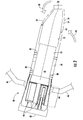
- Fig. 2 provides a simplified side cross-section view of an exemplary combustor 20 according to various embodiments of the present invention. As shown in Fig. 2 , a casing 40 and an end cover 42 may combine to contain the compressed working fluid 18 flowing to the combustor 20.
- a cap assembly 44 may extend radially across at least a portion of the combustor 20, and one or more fuel nozzles 46 may be radially arranged across the cap assembly 44 to supply the fuel 22 to a combustion chamber 48 downstream from the cap assembly 44.
- a liner 50 may circumferentially surround at least a portion of the combustion chamber 48, and a transition duct 52 downstream from the liner 50 may connect the combustion chamber 48 to the inlet of the turbine 26.
- An impingement sleeve 54 with flow holes 56 may circumferentially surround the transition duct 52, and a flow sleeve 58 may circumferentially surround the liner 50.
- the compressed working fluid 18 may pass through the flow holes 56 in the impingement sleeve 54 to flow through an annular passage 60 outside of the transition duct 52 and liner 50 to provide convective cooling to the transition duct 52 and liner 50.
- the compressed working fluid 18 When the compressed working fluid 18 reaches the end cover 42, the compressed working fluid 18 reverses direction to flow through the fuel nozzles 46 and cap assembly 44 into the combustion chamber 48.
- each fuel nozzle 46 may generally include a center body 62 surrounded by a shroud 64 to define an annular passage 66 between the center body 62 and the shroud 64.
- the center body 62 generally extends axially from the end cover 42 toward the cap assembly 44 to provide fluid communication for the fuel 22, diluents, and/or other additives to flow from the end cover 42, through the center body 62, and into the combustion chamber 48.
- the shroud 64 may include a bellmouth opening 68 to enhance the radial distribution of the compressed working fluid 18 flowing through the annular passage 66 between the center body 62 and the shroud 64.
- one or more vanes 70 may extend radially between the center body 62 and the shroud 64 to impart a tangential swirl to the compressed working fluid 18 to enhance mixing between the compressed working fluid 18 and the fuel 22 prior to combustion.
- the combustor 20 may further include one or more fuel injectors 80 downstream from the fuel nozzles 46 that that may provide a late lean injection of fuel 22 and compressed working fluid 18 for combustion.
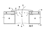
- the present invention is not limited to any particular fuel injector 80 unless specifically recited in the claims, and Fig. 4 provides an enlarged side cross-section view of an exemplary fuel injector 80 within the scope of the present invention.
- the fuel injector 80 may include a tube 82 or other passage that provides fluid communication through the flow sleeve 58 and the liner 50 into the combustion chamber 48.
- Fig. 4 the fuel injector 80 may include a tube 82 or other passage that provides fluid communication through the flow sleeve 58 and the liner 50 into the combustion chamber 48.
- the tube 82 is substantially perpendicular to the flow sleeve 58 and liner 50 to inject the fuel-air mixture transverse to the combustion chamber 48; however, in other embodiments, the tube 82 may be angled axially and/or circumferentially with respect to the flow sleeve 58 and/or liner 50.
- the flow sleeve 58 may include an internal fuel passage 84, and each tube 82 may include one or more fuel ports 86 circumferentially arranged around the tube 82.
- the internal fuel passage 84 may supply the same or a different fuel 22 to the fuel ports 86 than is supplied to the fuel nozzles 34.
- the fuel ports 86 may thus provide fluid communication for the fuel 22 to flow into the tubes 82 to allow the fuel 22 and compressed working fluid 18 to mix while flowing through the tubes 82 and into the combustion chamber 48.
- the tubes 82 may supply a lean mixture of fuel 22 and compressed working fluid 18 for additional combustion to raise the temperature, and thus the efficiency, of the combustor 20.
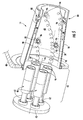
- Fig. 5 provides an upstream partial perspective side cross-section view of the combustor 20 shown in Fig. 2 to illustrate the position of the fuel injectors 80 with respect to the fuel nozzles 46.
- the vanes 70 in the fuel nozzles 46 impart a tangential swirl to the fuel 22 and compressed working fluid 18 flowing through the annular passage 66 between the center body 62 and the shroud 64.
- each fuel nozzle 46 supplies a separate swirling flow of fuel 90 that slowly spirals downstream through the combustion chamber 48 as it combusts.
- Fig. 5 provides an upstream partial perspective side cross-section view of the combustor 20 shown in Fig. 2 to illustrate the position of the fuel injectors 80 with respect to the fuel nozzles 46.
- the vanes 70 in the fuel nozzles 46 impart a tangential swirl to the fuel 22 and compressed working fluid 18 flowing through the annular passage 66 between the center body 62 and the shroud 64.
- each fuel nozzle 46 supplies a separate swirling flow of fuel 90 that slowly
- a first set of fuel injectors 92 are circumferentially arranged around the liner 50 downstream from the fuel nozzles 46, and a second set of fuel injectors 94 are circumferentially arranged around the liner 50 downstream from the first set of fuel injectors 92.
- Each fuel injector 80 in each set of fuel injectors 92, 94 has the same axial position as the other fuel injectors 80 in the same set 92, 94.
- each fuel injector 80 in the each set of fuel injectors 92, 94 is circumferentially indexed or clocked with respect to the swirling flow of fuel 90 from a different fuel nozzle 46.
- each fuel injector 80 is angled axially and circumferentially so that each fuel injector 80 intersects the liner 50 at a compound angle to further enhance the benefit of clocking the fuel injectors 80 with respect to the swirling flow of fuel 90.
- the optimum amount of clocking or circumferential offset 96 between each fuel injector 80 and the swirling flow of fuel 90 may be varies according to various factors, such as the number of fuel nozzles 46, the amount of swirl induced by each fuel nozzle 46, the number of fuel injectors 80, the axial and/or circumferential angle of the fuel injectors 80, and the anticipated operating level for the combustor 20.
- the optimum clocking or circumferential offset 96 may be approximately ⁇ 2-15 degrees for a combustor 20 with five or more fuel nozzles 46, approximately ⁇ 10-25 degrees for a combustor 20 with four fuel nozzles 46, and approximately ⁇ 20-45 degrees for a combustor 20 with three or fewer fuel nozzles 46.
- the particular clocking or circumferential offset 96 for each embodiment may be determined empirically through computational fluid dynamic models and/or through experimentation.
- Fig. 6 provides a set of emissions curves for a particular circumferential offset 96 for the fuel nozzles 46 and first and second sets of fuel injectors 92, 94.
- the carbon monoxide emissions curve 100 indicates that carbon monoxide emissions using only the fuel nozzles 46 increase significantly below lower combustion temperatures associated with reduced fuel flow and/or part load operation (turndown).
- Supplying additional fuel 22 through the first set of fuel injectors 92 or through both the first and second sets of fuel injectors 92, 94 during turndown operations shifts the carbon monoxide emissions curve 100 to the right.
- the NO X emissions curve 102 indicates that NO X emissions using only the fuel nozzles 46 increase significantly above higher combustion temperatures associated with full load operations, and supplying additional fuel 22 through the first set of fuel injectors 92 or through both the first and second sets of fuel injectors 92, 94 during full load operations shifts the NO X emissions curve 102 to the right.
- the NO X emissions curves 102 indicate that the lean fuel 22 supplied by the first and second set of fuel injectors 92, 94 enable higher combustion temperatures before the NO X emissions increase significantly. Additional emissions curves 100, 102 as shown in Fig.
- first and second sets of fuel injectors 92, 94 clocked at different circumferential offsets 96 may be empirically or experimentally created for first and second sets of fuel injectors 92, 94 clocked at different circumferential offsets 96, and the optimum circumferential offset 96 may be selected based on the collection of emissions curves 100, 102 and anticipated operating schedule for the combustor 20.
- Figs. 1-5 may provide one or more advantages over existing systems.
- the various combinations of axial positions of fuel injectors 80 clocked to the swirling flow of fuel 90 may allow for higher combustor temperatures before producing a dramatic increase in NO X emissions.
- the wider range of combustor temperatures thus enhances the thermodynamic efficiency of the gas turbine 10 without a corresponding increase in undesirable emissions.
Landscapes
- Engineering & Computer Science (AREA)
- Chemical & Material Sciences (AREA)
- Combustion & Propulsion (AREA)
- Mechanical Engineering (AREA)
- General Engineering & Computer Science (AREA)
Abstract
A system for supplying fuel to a combustor (20) includes a combustion chamber (48) and a liner (50) that circumferentially surrounds at least a portion of the combustion chamber (48). A plurality of fuel nozzles (46) are radially arranged across the combustor (20) upstream from the combustion chamber (48) to supply a swirling flow of fuel into the combustion chamber (48). A first fuel injector (80) downstream from the plurality of fuel nozzles (46) provides fluid communication for fuel to flow through the liner (50) and into the combustion chamber (48). The first fuel injector (80) is circumferentially clocked with respect to the swirling flow of fuel in the combustion chamber (48).
Description
- The present invention generally involves a system for supplying fuel to a combustor. In particular embodiments, the combustor may be incorporated into a gas turbine or other turbo-machine.
- Combustors are commonly used in industrial and power generation operations to ignite fuel to produce combustion gases having a high temperature and pressure. For example, turbo-machines such as gas turbines typically include one or more combustors to generate power or thrust. A typical gas turbine includes an inlet section, a compressor section, a combustion section, a turbine section, and an exhaust section. The inlet section cleans and conditions a working fluid (e.g., air) and supplies the working fluid to the compressor section. The compressor section increases the pressure of the working fluid and supplies a compressed working fluid to the combustion section. The combustion section mixes fuel with the compressed working fluid and ignites the mixture to generate combustion gases having a high temperature and pressure. The combustion gases flow to the turbine section where they expand to produce work. For example, expansion of the combustion gases in the turbine section may rotate a shaft connected to a generator to produce electricity.
- The combustion section may include one or more combustors annularly arranged between the compressor section and the turbine section, and the temperature of the combustion gases directly influences the thermodynamic efficiency, design margins, and resulting emissions of the combustor. For example, higher combustion gas temperatures generally improve the thermodynamic efficiency of the combustor. However, higher combustion gas temperatures also promote flame holding conditions in which the combustion flame migrates towards the fuel being supplied by nozzles, possibly causing accelerated damage to the nozzles in a relatively short amount of time. In addition, higher combustion gas temperatures generally increase the disassociation rate of diatomic nitrogen, increasing the production of nitrogen oxides (NOX) for the same residence time in the combustor. Conversely, a lower combustion gas temperature associated with reduced fuel flow and/or part load operation (turndown) generally reduces the chemical reaction rates of the combustion gases, increasing the production of carbon monoxide and unburned hydrocarbons for the same residence time in the combustor.
- In a particular combustor design, the combustor may include a cap assembly that extends radially across at least a portion of the combustor, and one or more fuel nozzles may be radially arranged across the cap assembly to supply fuel to the combustor. The fuel nozzles may include swirler vanes and/or other flow guides to enhance mixing between the fuel and the compressed working fluid to produce a lean fuel-air mixture for combustion. The swirling fuel-air mixture flows into a combustion chamber where it ignites to generate the combustion gases. The combustor may further include one or more fuel injectors circumferentially arranged around the combustion chamber to supply additional fuel for combustion. The additional fuel supplied by the fuel injectors increases the firing temperature of the combustor without producing a corresponding increase in the residence time of the combustion gases inside the combustion chamber.
- Although effective at enabling higher operating temperatures, the axial and circumferential location of the fuel injectors around the combustion chamber may have a substantial impact on undesirable emissions and/or component wear. For example, fuel injectors that inject fuel directly into the combusting fuel-air mixture flowing from the fuel nozzles may produce undesirable hot streaks inside the combustor that may increase the NOX emissions and reduce the low cycle fatigue of components. Alternately, fuel injectors that inject fuel too far from the combusting fuel-air mixture flowing from the fuel nozzles may lead to incomplete combustion of the fuel, increasing the production of carbon monoxide and unburned hydrocarbons. As a result, a system for supplying fuel to a combustor that indexes or clocks the fuel injectors to the fuel nozzles and/or the swirling fuel-air mixture flowing from the fuel nozzles may allow for increased combustor temperatures over a wider range of operating conditions without a corresponding increase in undesirable emissions and/or component wear.
- Aspects and advantages of the invention are set forth below in the following description, or may be obvious from the description, or may be learned through practice of the invention.
- One aspect of the present invention is a system for supplying fuel to a combustor that includes a combustion chamber and a liner that circumferentially surrounds at least a portion of the combustion chamber. A plurality of fuel nozzles are radially arranged across the combustor upstream from the combustion chamber to supply a swirling flow of fuel into the combustion chamber. A first fuel injector downstream from the plurality of fuel nozzles provides fluid communication for fuel to flow through the liner and into the combustion chamber. The first fuel injector is circumferentially clocked with respect to the swirling flow of fuel in the combustion chamber.
- Another aspect of the present invention is a system for supplying fuel to a combustor that includes a combustion chamber and a liner that circumferentially surrounds at least a portion of the combustion chamber. A plurality of fuel nozzles are radially arranged across the combustor upstream from the combustion chamber to supply a swirling flow of fuel into the combustion chamber. A first set of fuel injectors are circumferentially arranged around the liner downstream from the plurality of fuel nozzles. The first set of fuel injectors provide fluid communication for fuel to flow through the liner and into the combustion chamber and are circumferentially clocked with respect to the swirling flow of fuel in the combustion chamber.
- The present invention may also reside in a gas turbine having a compressor, a combustor downstream from the compressor, and a turbine downstream from the combustor. A plurality of fuel nozzles are radially arranged inside the combustor, and a combustion chamber is downstream from the plurality of fuel nozzles. The plurality of fuel nozzles supply a swirling flow of fuel into the combustion chamber. A first set of fuel injectors are circumferentially arranged around the combustion chamber downstream from the plurality of fuel nozzles. The first set of fuel injectors provide fluid communication for fuel to flow into the combustion chamber and are circumferentially clocked with respect to the swirling flow of fuel in the combustion chamber.
- Those of ordinary skill in the art will better appreciate the features and aspects of such embodiments, and others, upon review of the specification.
- A full and enabling disclosure of the present invention, including the best mode thereof to one skilled in the art, is set forth more particularly in the remainder of the specification, including reference to the accompanying figures, in which:
-
Fig. 1 is a functional block diagram of an exemplary gas turbine within the scope of the present invention; -
Fig. 2 is a simplified side cross-section view of an exemplary combustor according to various embodiments of the present invention; -
Fig. 3 is an enlarged partial side cross-section view of the cap assembly and fuel nozzles shown inFig. 2 ; -
Fig. 4 is an enlarged side cross-section view of an exemplary fuel injector shown inFig. 2 ; -
Fig. 5 is an upstream partial perspective side cross-section view of the combustor shown inFig. 2 according to an embodiment of the present invention; and -
Fig. 6 is a set of emissions curves at various temperatures. - Reference will now be made in detail to present embodiments of the invention, one or more examples of which are illustrated in the accompanying drawings. The detailed description uses numerical and letter designations to refer to features in the drawings. Like or similar designations in the drawings and description have been used to refer to like or similar parts of the invention. As used herein, the terms "first", "second", and "third" may be used interchangeably to distinguish one component from another and are not intended to signify location or importance of the individual components. The terms "upstream," "downstream," "radially," and "axially" refer to the relative direction with respect to fluid flow in a fluid pathway. For example, "upstream" refers to the direction from which the fluid flows, and "downstream" refers to the direction to which the fluid flows. Similarly, "radially" refers to the relative direction substantially perpendicular to the fluid flow, and "axially" refers to the relative direction substantially parallel to the fluid flow.
- Each example is provided by way of explanation of the invention, not limitation of the invention. In fact, it will be apparent to those skilled in the art that modifications and variations can be made in the present invention without departing from the scope or spirit thereof. For instance, features illustrated or described as part of one embodiment may be used on another embodiment to yield a still further embodiment. Thus, it is intended that the present invention covers such modifications and variations as come within the scope of the appended claims and their equivalents.
- Various embodiments of the present invention include a system for supplying fuel to a combustor. The combustor generally includes a cap assembly that extends radially across at least a portion of the combustor, and a plurality of fuel nozzles radially arranged in the cap assembly supply a swirling flow of fuel into a combustion chamber. One or more fuel injectors may be circumferentially arranged around the combustion chamber to supply fuel into the combustion chamber, and each fuel injector is circumferentially indexed or clocked with respect to the swirling flow of fuel in the combustion chamber. In particular embodiments, the fuel injectors may be axially aligned with one another, while in other particular embodiments, the fuel injectors may be axially staggered inside the combustion chamber. Alternately or in addition, the fuel injectors may intersect the combustion chamber perpendicular to a tangent of the combustion chamber or at a compound angle, depending on the particular embodiment. As a result, various embodiments of the present invention may allow extended combustor operating conditions, extend the life and/or maintenance intervals for various combustor components, maintain adequate design margins of flame holding, and/or reduce undesirable emissions. Although exemplary embodiments of the present invention will be described generally in the context of a combustor incorporated into a gas turbine for purposes of illustration, one of ordinary skill in the art will readily appreciate that embodiments of the present invention may be applied to any combustor incorporated into any turbo-machine and are not limited to a gas turbine combustor unless specifically recited in the claims.
- Referring now to the drawings, wherein identical numerals indicate the same elements throughout the figures,
Fig. 1 provides a functional block diagram of anexemplary gas turbine 10 that may incorporate various embodiments of the present invention. As shown, thegas turbine 10 generally includes aninlet section 12 that may include a series of filters, cooling coils, moisture separators, and/or other devices to purify and otherwise condition a working fluid (e.g., air) 14 entering thegas turbine 10. The workingfluid 14 flows to a compressor section where acompressor 16 progressively imparts kinetic energy to the workingfluid 14 to produce a compressed workingfluid 18 at a highly energized state. The compressed workingfluid 18 flows to a combustion section where one ormore combustors 20 ignitefuel 22 with the compressed workingfluid 18 to producecombustion gases 24 having a high temperature and pressure. Thecombustion gases 24 flow through a turbine section to produce work. For example, aturbine 26 may connect to ashaft 28 so that rotation of theturbine 26 drives thecompressor 16 to produce the compressed workingfluid 18. Alternately or in addition, theshaft 28 may connect theturbine 26 to agenerator 30 for producing electricity.Exhaust gases 32 from theturbine 26 flow through anexhaust section 34 that may connect theturbine 26 to anexhaust stack 36 downstream from theturbine 26. Theexhaust section 34 may include, for example, a heat recovery steam generator (not shown) for cleaning and extracting additional heat from theexhaust gases 32 prior to release to the environment. - The
combustors 20 may be any type of combustor known in the art, and the present invention is not limited to any particular combustor design unless specifically recited in the claims.Fig. 2 provides a simplified side cross-section view of anexemplary combustor 20 according to various embodiments of the present invention. As shown inFig. 2 , acasing 40 and anend cover 42 may combine to contain the compressed workingfluid 18 flowing to thecombustor 20. Acap assembly 44 may extend radially across at least a portion of thecombustor 20, and one ormore fuel nozzles 46 may be radially arranged across thecap assembly 44 to supply thefuel 22 to acombustion chamber 48 downstream from thecap assembly 44. Aliner 50 may circumferentially surround at least a portion of thecombustion chamber 48, and atransition duct 52 downstream from theliner 50 may connect thecombustion chamber 48 to the inlet of theturbine 26. Animpingement sleeve 54 with flow holes 56 may circumferentially surround thetransition duct 52, and aflow sleeve 58 may circumferentially surround theliner 50. In this manner, the compressed workingfluid 18 may pass through the flow holes 56 in theimpingement sleeve 54 to flow through anannular passage 60 outside of thetransition duct 52 andliner 50 to provide convective cooling to thetransition duct 52 andliner 50. When the compressed workingfluid 18 reaches theend cover 42, the compressed workingfluid 18 reverses direction to flow through thefuel nozzles 46 andcap assembly 44 into thecombustion chamber 48. - The present invention is not limited to any
particular cap assembly 44 orfuel nozzles 46 unless specifically recited in the claims, andFig. 3 provides an enlarged partial side cross-section view of anexemplary cap assembly 44 andfuel nozzles 46 within the scope of the present invention. As shown inFig. 3 , eachfuel nozzle 46 may generally include acenter body 62 surrounded by ashroud 64 to define anannular passage 66 between thecenter body 62 and theshroud 64. Thecenter body 62 generally extends axially from theend cover 42 toward thecap assembly 44 to provide fluid communication for thefuel 22, diluents, and/or other additives to flow from theend cover 42, through thecenter body 62, and into thecombustion chamber 48. Theshroud 64 may include abellmouth opening 68 to enhance the radial distribution of the compressed workingfluid 18 flowing through theannular passage 66 between thecenter body 62 and theshroud 64. In addition, one ormore vanes 70 may extend radially between thecenter body 62 and theshroud 64 to impart a tangential swirl to the compressed workingfluid 18 to enhance mixing between the compressed workingfluid 18 and thefuel 22 prior to combustion. - Referring back to
Fig. 2 , thecombustor 20 may further include one ormore fuel injectors 80 downstream from thefuel nozzles 46 that that may provide a late lean injection offuel 22 and compressed workingfluid 18 for combustion. The present invention is not limited to anyparticular fuel injector 80 unless specifically recited in the claims, andFig. 4 provides an enlarged side cross-section view of anexemplary fuel injector 80 within the scope of the present invention. As shown inFig. 4 , thefuel injector 80 may include atube 82 or other passage that provides fluid communication through theflow sleeve 58 and theliner 50 into thecombustion chamber 48. In the exemplary embodiment shown inFig. 4 , thetube 82 is substantially perpendicular to theflow sleeve 58 andliner 50 to inject the fuel-air mixture transverse to thecombustion chamber 48; however, in other embodiments, thetube 82 may be angled axially and/or circumferentially with respect to theflow sleeve 58 and/orliner 50. - The
flow sleeve 58 may include aninternal fuel passage 84, and eachtube 82 may include one ormore fuel ports 86 circumferentially arranged around thetube 82. Theinternal fuel passage 84 may supply the same or adifferent fuel 22 to thefuel ports 86 than is supplied to thefuel nozzles 34. Thefuel ports 86 may thus provide fluid communication for thefuel 22 to flow into thetubes 82 to allow thefuel 22 and compressed workingfluid 18 to mix while flowing through thetubes 82 and into thecombustion chamber 48. In this manner, thetubes 82 may supply a lean mixture offuel 22 and compressed workingfluid 18 for additional combustion to raise the temperature, and thus the efficiency, of thecombustor 20. -
Fig. 5 provides an upstream partial perspective side cross-section view of thecombustor 20 shown inFig. 2 to illustrate the position of thefuel injectors 80 with respect to thefuel nozzles 46. As shown inFig. 5 , thevanes 70 in thefuel nozzles 46 impart a tangential swirl to thefuel 22 and compressed workingfluid 18 flowing through theannular passage 66 between thecenter body 62 and theshroud 64. As a result, eachfuel nozzle 46 supplies a separate swirling flow offuel 90 that slowly spirals downstream through thecombustion chamber 48 as it combusts. In the particular embodiment shown inFig. 5 , a first set offuel injectors 92 are circumferentially arranged around theliner 50 downstream from thefuel nozzles 46, and a second set offuel injectors 94 are circumferentially arranged around theliner 50 downstream from the first set offuel injectors 92. Eachfuel injector 80 in each set offuel injectors other fuel injectors 80 in thesame set fuel injector 80 in the each set offuel injectors fuel 90 from adifferent fuel nozzle 46. As used herein, the term "clocked" or "clocking" refers to positioning eachfuel injector 80 at a desired circumferential offset 96 with respect to the swirling flow offuel 90. The circumferential offset 96 between eachfuel injector 80 and the swirling flow offuel 90 avoids or reduces the undesirable hot streaks and incomplete combustion of thefuel 22 associated with previous late lean injections systems and methods. In addition, in the particular embodiment shown inFig. 5 , eachfuel injector 80 is angled axially and circumferentially so that eachfuel injector 80 intersects theliner 50 at a compound angle to further enhance the benefit of clocking thefuel injectors 80 with respect to the swirling flow offuel 90. - The optimum amount of clocking or circumferential offset 96 between each
fuel injector 80 and the swirling flow offuel 90 may be varies according to various factors, such as the number offuel nozzles 46, the amount of swirl induced by eachfuel nozzle 46, the number offuel injectors 80, the axial and/or circumferential angle of thefuel injectors 80, and the anticipated operating level for thecombustor 20. For example, the optimum clocking or circumferential offset 96 may be approximately ±2-15 degrees for a combustor 20 with five ormore fuel nozzles 46, approximately ±10-25 degrees for a combustor 20 with fourfuel nozzles 46, and approximately ±20-45 degrees for a combustor 20 with three orfewer fuel nozzles 46. - The particular clocking or circumferential offset 96 for each embodiment may be determined empirically through computational fluid dynamic models and/or through experimentation. For example,
Fig. 6 provides a set of emissions curves for a particular circumferential offset 96 for thefuel nozzles 46 and first and second sets offuel injectors fuel nozzles 46 increase significantly below lower combustion temperatures associated with reduced fuel flow and/or part load operation (turndown). Supplyingadditional fuel 22 through the first set offuel injectors 92 or through both the first and second sets offuel injectors fuel nozzles 46 increase significantly above higher combustion temperatures associated with full load operations, and supplyingadditional fuel 22 through the first set offuel injectors 92 or through both the first and second sets offuel injectors lean fuel 22 supplied by the first and second set offuel injectors Fig. 6 may be empirically or experimentally created for first and second sets offuel injectors circumferential offsets 96, and the optimum circumferential offset 96 may be selected based on the collection ofemissions curves combustor 20. - The various embodiments described and illustrated with respect to
Figs. 1-5 may provide one or more advantages over existing systems. For example, the various combinations of axial positions offuel injectors 80 clocked to the swirling flow offuel 90 may allow for higher combustor temperatures before producing a dramatic increase in NOX emissions. The wider range of combustor temperatures thus enhances the thermodynamic efficiency of thegas turbine 10 without a corresponding increase in undesirable emissions. - This written description uses examples to disclose the invention, including the best mode, and also to enable any person skilled in the art to practice the invention, including making and using any devices or systems and performing any incorporated methods. The patentable scope of the invention is defined by the claims, and may include other examples that occur to those skilled in the art. Such other examples are intended to be within the scope of the claims if they include structural elements that do not differ from the literal language of the claims, or if they include equivalent structural elements with insubstantial differences from the literal language of the claims.
Claims (11)
- A system for supplying fuel to a combustor (20), comprising:a combustion chamber (48);a liner (50) that circumferentially surrounds at least a portion of the combustion chamber (48);a plurality of fuel nozzles (46) radially arranged across the combustor (20) upstream from the combustion chamber (48), wherein the plurality of fuel nozzles (46) supply a swirling flow of fuel (90) into the combustion chamber (48);at least one first fuel injector (80) downstream from the plurality of fuel nozzles (46), wherein the at least one first fuel injector (80) provides fluid communication for fuel to flow through the liner (50) and into the combustion chamber (48); andwherein the at least one first fuel injector (80) is circumferentially clocked with respect to the swirling flow of fuel (90) in the combustion chamber (48).
- The system as in claim 1, wherein each fuel nozzle (46) comprises a plurality of swirler vanes (70) that extend radially between a center body (62) and a shroud (64).
- The system as in claims 1 or 2, wherein the at least one first fuel injector (80) comprises a first set of fuel injectors (92).
- The system as in any of claims 1 to 3, wherein the at least one first fuel injector (80) intersects the liner (50) at a compound angle.
- The system as in claim 1, further comprising at least one second fuel injector downstream from the plurality of fuel nozzles (46), wherein the second fuel injector (94) provides fluid communication for fuel to flow through the liner (50) and into the combustion chamber (48), and wherein the second fuel injector (94) is circumferentially clocked with respect to the swirling flow of fuel (90) in the combustion chamber (48).
- The system as in claim 5, wherein the at least one second fuel injectors comprises a second set of fuel injectors (94).
- The system as in claim 5 or 6, wherein the at least one second fuel injector (94) is axially aligned substantially even with the first fuel injector (80).
- The system as in claim 5 or 6, wherein the at least one second fuel injector (94) is axially aligned in the combustion chamber (48) downstream from the first fuel injector (92).
- The system as in claim 5 or 6, wherein the at least one second fuel injector (94) intersects the liner (50) at a compound angle.
- The system as in any preceding claim, further comprising a flow sleeve (58) that circumferentially surrounds at least a portion of the liner (50) and a fuel plenum inside the flow sleeve (58) in fluid communication with the first fuel injector (80).
- A gas turbine, comprising:a compressor (16);a combustor (20) downstream from the compressor (16);a turbine (26) downstream from the combustor (20); and the system of any of claims 1 to 10.
Applications Claiming Priority (1)
| Application Number | Priority Date | Filing Date | Title |
|---|---|---|---|
| US13/723,322 US20140174090A1 (en) | 2012-12-21 | 2012-12-21 | System for supplying fuel to a combustor |
Publications (1)
| Publication Number | Publication Date |
|---|---|
| EP2746666A2 true EP2746666A2 (en) | 2014-06-25 |
Family
ID=49918416
Family Applications (1)
| Application Number | Title | Priority Date | Filing Date |
|---|---|---|---|
| EP13198227.4A Withdrawn EP2746666A2 (en) | 2012-12-21 | 2013-12-18 | System for supplying fuel to a combustor |
Country Status (4)
| Country | Link |
|---|---|
| US (1) | US20140174090A1 (en) |
| EP (1) | EP2746666A2 (en) |
| JP (1) | JP2014122784A (en) |
| CN (1) | CN204026742U (en) |
Cited By (2)
| Publication number | Priority date | Publication date | Assignee | Title |
|---|---|---|---|---|
| US11156164B2 (en) | 2019-05-21 | 2021-10-26 | General Electric Company | System and method for high frequency accoustic dampers with caps |
| US11174792B2 (en) | 2019-05-21 | 2021-11-16 | General Electric Company | System and method for high frequency acoustic dampers with baffles |
Families Citing this family (12)
| Publication number | Priority date | Publication date | Assignee | Title |
|---|---|---|---|---|
| US9097424B2 (en) * | 2012-03-12 | 2015-08-04 | General Electric Company | System for supplying a fuel and working fluid mixture to a combustor |
| DE102013202984A1 (en) * | 2013-02-22 | 2014-08-28 | Siemens Aktiengesellschaft | Method for operating a gas turbine below its rated power |
| US20150052905A1 (en) * | 2013-08-20 | 2015-02-26 | General Electric Company | Pulse Width Modulation for Control of Late Lean Liquid Injection Velocity |
| US20160047316A1 (en) * | 2014-08-14 | 2016-02-18 | General Electric Company | Systems and apparatus relating to gas turbine combustors |
| JP6551820B2 (en) | 2014-09-29 | 2019-07-31 | 三菱日立パワーシステムズ株式会社 | Combustor and gas turbine provided with the same |
| KR102096434B1 (en) * | 2015-07-07 | 2020-04-02 | 한화에어로스페이스 주식회사 | Combustor |
| DE102015217469A1 (en) * | 2015-09-11 | 2017-03-16 | Eos Gmbh Electro Optical Systems | Method and device for producing a three-dimensional object |
| WO2018026382A1 (en) * | 2016-08-03 | 2018-02-08 | Siemens Aktiengesellschaft | Ducting arrangement with injector assemblies configured to form a shielding flow of air injected into a combustion stage in a gas turbine engine |
| WO2018026381A1 (en) * | 2016-08-03 | 2018-02-08 | Siemens Aktiengesellschaft | Combustion system with injector assemblies arranged to recapture cooling air in a combustor wall to form a shielding flow of air in a combustion stage |
| KR102164620B1 (en) * | 2019-06-19 | 2020-10-12 | 두산중공업 주식회사 | Combustor and gas turbine including the same |
| US12379108B2 (en) | 2023-01-06 | 2025-08-05 | Ge Vernova Infrastructure Technology Llc | Method of operating gas turbine combustor with multiple fuel stages |
| US12560327B2 (en) | 2023-01-06 | 2026-02-24 | Ge Vernova Infrastructure Technology Llc | Multi-stage axial fuel injection system with discrete air supplies |
Family Cites Families (4)
| Publication number | Priority date | Publication date | Assignee | Title |
|---|---|---|---|---|
| US4928481A (en) * | 1988-07-13 | 1990-05-29 | Prutech Ii | Staged low NOx premix gas turbine combustor |
| JP2950720B2 (en) * | 1994-02-24 | 1999-09-20 | 株式会社東芝 | Gas turbine combustion device and combustion control method therefor |
| US7886545B2 (en) * | 2007-04-27 | 2011-02-15 | General Electric Company | Methods and systems to facilitate reducing NOx emissions in combustion systems |
| US8991192B2 (en) * | 2009-09-24 | 2015-03-31 | Siemens Energy, Inc. | Fuel nozzle assembly for use as structural support for a duct structure in a combustor of a gas turbine engine |
-
2012
- 2012-12-21 US US13/723,322 patent/US20140174090A1/en not_active Abandoned
-
2013
- 2013-12-18 EP EP13198227.4A patent/EP2746666A2/en not_active Withdrawn
- 2013-12-18 JP JP2013260722A patent/JP2014122784A/en active Pending
- 2013-12-20 CN CN201320849153.4U patent/CN204026742U/en not_active Expired - Fee Related
Non-Patent Citations (1)
| Title |
|---|
| None |
Cited By (2)
| Publication number | Priority date | Publication date | Assignee | Title |
|---|---|---|---|---|
| US11156164B2 (en) | 2019-05-21 | 2021-10-26 | General Electric Company | System and method for high frequency accoustic dampers with caps |
| US11174792B2 (en) | 2019-05-21 | 2021-11-16 | General Electric Company | System and method for high frequency acoustic dampers with baffles |
Also Published As
| Publication number | Publication date |
|---|---|
| CN204026742U (en) | 2014-12-17 |
| US20140174090A1 (en) | 2014-06-26 |
| JP2014122784A (en) | 2014-07-03 |
Similar Documents
| Publication | Publication Date | Title |
|---|---|---|
| EP2746666A2 (en) | System for supplying fuel to a combustor | |
| US9353950B2 (en) | System for reducing combustion dynamics and NOx in a combustor | |
| US9534790B2 (en) | Fuel injector for supplying fuel to a combustor | |
| US8904798B2 (en) | Combustor | |
| EP2657611B1 (en) | System for supplying fuel to a combustor | |
| US9151500B2 (en) | System for supplying a fuel and a working fluid through a liner to a combustion chamber | |
| EP2629017B1 (en) | Combustor | |
| US8984887B2 (en) | Combustor and method for supplying fuel to a combustor | |
| US9951956B2 (en) | Fuel nozzle assembly having a premix fuel stabilizer | |
| EP2584266B1 (en) | Combustor and method for conditioning flow through a combustor | |
| EP2634487A2 (en) | System and method for reducing combustion dynamics in a combustor | |
| US20140260263A1 (en) | Fuel injection insert for a turbine nozzle segment | |
| EP2741005A1 (en) | A fuel nozzle for a combustor of a gas turbine engine | |
| EP2634488A1 (en) | System and method for reducing combustion dynamics in a combustor | |
| EP3220047A1 (en) | Gas turbine flow sleeve mounting | |
| US20140311150A1 (en) | Fuel nozzle for a pre-mix combustor of a gas turbine engine | |
| US20170184310A1 (en) | System for Injecting a Liquid Fuel into a Combustion Gas Flow Field | |
| EP3933268A1 (en) | Combustor air flow path | |
| EP2592345A1 (en) | Combustor and method for supplying fuel to a combustor | |
| EP2592349A2 (en) | Combustor and method for supplying fuel to a combustor | |
| EP3314167A1 (en) | Fuel nozzle assembly having a premix flame stabilizer | |
| CN107191967B (en) | Combustion liner cooling | |
| US10228135B2 (en) | Combustion liner cooling |
Legal Events
| Date | Code | Title | Description |
|---|---|---|---|
| PUAI | Public reference made under article 153(3) epc to a published international application that has entered the european phase |
Free format text: ORIGINAL CODE: 0009012 |
|
| 17P | Request for examination filed |
Effective date: 20131218 |
|
| AK | Designated contracting states |
Kind code of ref document: A2 Designated state(s): AL AT BE BG CH CY CZ DE DK EE ES FI FR GB GR HR HU IE IS IT LI LT LU LV MC MK MT NL NO PL PT RO RS SE SI SK SM TR |
|
| AX | Request for extension of the european patent |
Extension state: BA ME |
|
| STAA | Information on the status of an ep patent application or granted ep patent |
Free format text: STATUS: THE APPLICATION IS DEEMED TO BE WITHDRAWN |
|
| 18D | Application deemed to be withdrawn |
Effective date: 20170701 |