EP2746497A2 - Ensemble de verrouillage - Google Patents
Ensemble de verrouillage Download PDFInfo
- Publication number
- EP2746497A2 EP2746497A2 EP13197992.4A EP13197992A EP2746497A2 EP 2746497 A2 EP2746497 A2 EP 2746497A2 EP 13197992 A EP13197992 A EP 13197992A EP 2746497 A2 EP2746497 A2 EP 2746497A2
- Authority
- EP
- European Patent Office
- Prior art keywords
- assembly
- spindle
- locking
- interior
- operator
- Prior art date
- Legal status (The legal status is an assumption and is not a legal conclusion. Google has not performed a legal analysis and makes no representation as to the accuracy of the status listed.)
- Withdrawn
Links
Images


Classifications
-
- E—FIXED CONSTRUCTIONS
- E05—LOCKS; KEYS; WINDOW OR DOOR FITTINGS; SAFES
- E05B—LOCKS; ACCESSORIES THEREFOR; HANDCUFFS
- E05B47/00—Operating or controlling locks or other fastening devices by electric or magnetic means
- E05B47/02—Movement of the bolt by electromagnetic means; Adaptation of locks, latches, or parts thereof, for movement of the bolt by electromagnetic means
-
- E—FIXED CONSTRUCTIONS
- E05—LOCKS; KEYS; WINDOW OR DOOR FITTINGS; SAFES
- E05B—LOCKS; ACCESSORIES THEREFOR; HANDCUFFS
- E05B13/00—Devices preventing the key or the handle or both from being used
- E05B13/10—Devices preventing the key or the handle or both from being used formed by a lock arranged in the handle
- E05B13/106—Devices preventing the key or the handle or both from being used formed by a lock arranged in the handle for handles pivoted about an axis perpendicular to the wing
- E05B13/108—Devices preventing the key or the handle or both from being used formed by a lock arranged in the handle for handles pivoted about an axis perpendicular to the wing the lock coaxial with spindle
-
- E—FIXED CONSTRUCTIONS
- E05—LOCKS; KEYS; WINDOW OR DOOR FITTINGS; SAFES
- E05B—LOCKS; ACCESSORIES THEREFOR; HANDCUFFS
- E05B47/00—Operating or controlling locks or other fastening devices by electric or magnetic means
- E05B47/06—Controlling mechanically-operated bolts by electro-magnetically-operated detents
- E05B47/0676—Controlling mechanically-operated bolts by electro-magnetically-operated detents by disconnecting the handle
- E05B47/0684—Controlling mechanically-operated bolts by electro-magnetically-operated detents by disconnecting the handle radially
- E05B47/0692—Controlling mechanically-operated bolts by electro-magnetically-operated detents by disconnecting the handle radially with a rectilinearly moveable coupling element
-
- E—FIXED CONSTRUCTIONS
- E05—LOCKS; KEYS; WINDOW OR DOOR FITTINGS; SAFES
- E05B—LOCKS; ACCESSORIES THEREFOR; HANDCUFFS
- E05B63/00—Locks or fastenings with special structural characteristics
- E05B63/16—Locks or fastenings with special structural characteristics with the handles on opposite sides moving independently
-
- E—FIXED CONSTRUCTIONS
- E05—LOCKS; KEYS; WINDOW OR DOOR FITTINGS; SAFES
- E05B—LOCKS; ACCESSORIES THEREFOR; HANDCUFFS
- E05B47/00—Operating or controlling locks or other fastening devices by electric or magnetic means
- E05B47/0001—Operating or controlling locks or other fastening devices by electric or magnetic means with electric actuators; Constructional features thereof
- E05B2047/0014—Constructional features of actuators or power transmissions therefor
- E05B2047/0018—Details of actuator transmissions
- E05B2047/0026—Clutches, couplings or braking arrangements
-
- E—FIXED CONSTRUCTIONS
- E05—LOCKS; KEYS; WINDOW OR DOOR FITTINGS; SAFES
- E05B—LOCKS; ACCESSORIES THEREFOR; HANDCUFFS
- E05B47/00—Operating or controlling locks or other fastening devices by electric or magnetic means
- E05B2047/0084—Key or electric means; Emergency release
- E05B2047/0086—Emergency release, e.g. key or electromagnet
-
- E—FIXED CONSTRUCTIONS
- E05—LOCKS; KEYS; WINDOW OR DOOR FITTINGS; SAFES
- E05B—LOCKS; ACCESSORIES THEREFOR; HANDCUFFS
- E05B47/00—Operating or controlling locks or other fastening devices by electric or magnetic means
- E05B47/0001—Operating or controlling locks or other fastening devices by electric or magnetic means with electric actuators; Constructional features thereof
- E05B47/0012—Operating or controlling locks or other fastening devices by electric or magnetic means with electric actuators; Constructional features thereof with rotary electromotors
Definitions
- the present invention relates to door locks, and, more particularly, to a lock assembly having a motor inside the interior operator handle.
- a typical motorized lock assembly has a motor for effecting the movement of a latch bolt, such as for example, from an extend position to a retracted position to facilitate the opening of a door.
- the motor is positioned off-axis from the drive spindle. In such an arrangement, however, the motor requires dedicated space on the lock chassis.
- the present invention provides a lock assembly wherein the motor is located inside the interior operator handle, and wherein the motor may be co-axial with the locking spindle assembly that operates the locking mechanism of the lock assembly.
- the invention in one form thereof, is directed to a lock assembly for a door.
- the lock assembly includes an exterior operator assembly having an exterior operator handle.
- An interior operator assembly has an interior operator handle.
- the interior operator handle has a mounting opening.
- a latch assembly has a bolt actuator mechanism and a bolt.
- An outer spindle preferably is operatively coupled to the latch assembly and drivably coupled to the interior operator assembly.
- the outer spindle preferably has a longitudinal bore and is rotatable about a first axis.
- a coupling mechanism preferably is drivably coupled to the outer spindle.
- a locking spindle assembly preferably is rotatably received in the longitudinal bore and rotatable about the first axis, and is configured to selectively operate the coupling mechanism to drivably couple the exterior operator assembly to the outer spindle.
- a motor drive assembly preferably includes a motor having a motor shaft. The motor preferably is positioned inside the mounting opening of the interior operator handle. The motor shaft preferably is drivably coupled to the locking spindle assembly to operate the coupling mechanism when the motor drive assembly is actuated.
- the invention in another form thereof, is directed to a lock assembly for use with a door.
- the lock assembly includes a latch assembly having a bolt actuator mechanism and a bolt.
- An outer spindle is operatively coupled to the bolt actuator mechanism of the latch assembly.
- the outer spindle preferably has a first end and a second end.
- the outer spindle preferably has a longitudinal bore and is configured for rotation about a first axis.
- An exterior lockset preferably includes an exterior operator assembly and a credential reader.
- the exterior operator assembly preferably has an exterior operator handle.
- a coupling mechanism preferably is drivably coupled to the second end of the outer spindle, and preferably is configured to selectively couple the exterior operator assembly to the outer spindle.
- a locking spindle assembly preferably is rotatably received in the longitudinal bore of the outer spindle for rotation about the first axis.
- the locking spindle assembly preferably includes a locking spindle tail member that extends from the first end of the outer spindle, and preferably a locking actuator spindle that extends from the second end of the outer spindle.
- the locking actuator spindle preferably is configured to selectively operate the coupling mechanism to drivably couple the exterior operator assembly to the outer spindle.
- An interior lockset preferably includes an interior operator assembly and a motor drive assembly.
- the interior operator assembly preferably includes an interior operator handle drivably coupled to the first end of the outer spindle.
- the interior operator handle preferably has a mounting opening configured to receive the motor drive assembly.
- the motor drive assembly preferably is electrically coupled to the credential reader.
- the credential reader preferably is configured to selectively actuate the motor drive assembly.
- the motor drive assembly preferably includes a motor having a motor shaft rotatable about the first axis.
- the motor shaft preferably is drivably coupled to the locking spindle tail member of the locking spindle assembly to operate the coupling mechanism when the motor drive assembly is actuated.
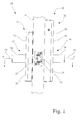
- a lock assembly 10 in accordance with the present invention for mounting on a door 12, and which includes an exterior lockset 14, an interior lockset 16, a latch assembly 18, and a strike 20.
- Exterior lockset 14 includes an exterior operator assembly 22, a credential reader 24, and an exterior escutcheon 26. Exterior operator assembly 22 includes an exterior operator handle 28.
- Interior lockset 16 includes an interior operator assembly 30, a control electronics module 32, an interior escutcheon 34, and a battery cover 36.
- Interior operator assembly 30 includes an interior operator handle 38.
- Control electronics module 32 is electrically connected to credential reader 24.
- interior operator assembly 30 includes a handle sleeve assembly 40.
- An exterior of handle sleeve assembly 40 is configured to mount interior operator handle 38.
- a distal end of handle sleeve assembly 40 is drivably coupled to an inside square drive spindle coupler 42.
- Within handle sleeve assembly 40 there is a chamber for mounting a motor drive assembly 44.
- Motor drive assembly 44 is electrically connected to control electronics module 32 via wire conductors 45.
- a spindle assembly 46 that includes an outer square spindle 48 within which there is rotatably received a locking spindle assembly 50.
- a coupling mechanism 52 is provided to selectively drivably couple exterior operator assembly 22 to outer square spindle 48.
- Locking spindle assembly 50 has a first end 50-1 that is mechanically coupled to a rotatable shaft of motor drive assembly 44.
- Locking spindle assembly 50 is operably coupled to coupling mechanism 52 to selectively couple and decouple exterior operator assembly 22 to outer square spindle 48, with the normal, or rest, state being a decoupled state.
- latch assembly 18 is configured with a bolt actuator mechanism 54 and a retractable bolt 56, as is customary in the art.
- Bolt actuator mechanism 54 is operable by a rotation of outer square spindle 48 of spindle assembly 46 to retract bolt 56.
- exterior operator handle 28, interior operator handle 38, motor drive assembly 44 and spindle assembly 46 are longitudinally aligned along an axis 58.
- Interior lockset 16 is configured such that during normal operation interior operator handle 38 is always operatively coupled to spindle assembly 46, and in particular, to outer square spindle 48 via inside square drive spindle coupler 42, and in turn to latch assembly 18. As such, in normal operation a rotation of interior operator handle 38 always will result in a retraction of bolt 56. Also, in normal operation motor drive assembly 44 is always operatively coupled to locking spindle assembly 50.
- exterior lockset 14 is configured such that exterior operator handle 28 is selectively coupled to latch assembly 18. In a locked condition, exterior operator handle 28 is decoupled from spindle assembly 46, and thus a rotation of exterior operator handle 28 does not result in a retraction of bolt 56. In an unlocked condition, exterior operator handle 28 is coupled to spindle assembly 46 via coupling mechanism 52 to operate latch assembly 18, and thus a rotation of exterior operator handle 28 will result in a retraction of bolt 56.
- the unlocked condition may be achieved by providing a valid credential, e.g., an RFID card, to be read by credential reader 24, which in turn sends a signal to control electronics module 32.
- Control electronics module 32 compares the read credential to a database of stored authorized credentials, and if a match is found, responds by operating motor drive assembly 44 to rotate the inner portion, i.e., locking spindle assembly 50, of spindle assembly 46 to activate coupling mechanism 52 to couple exterior operator handle 28 to latch assembly 18 via coupling mechanism 52 and outer square spindle 48 (see also Fig. 5 ).
- exterior lockset 14 is provided with a mechanical override in the form of a key operated interchangeable keyed lock core 60 that is operatively coupled to coupling mechanism 52, such that a valid operator key may be used to effect a coupling of exterior operator handle 28 to latch assembly 18.
- spindle assembly 46 includes the outer square spindle 48.
- Outer square spindle 48 has a first end 48-1, a second end 48-2, and a longitudinal bore 48-3 that extends between first end 48-1 and second end 48-2.
- Longitudinal bore 48-3 of outer square spindle 48 is sized to rotatably receive locking spindle assembly 50.
- Second end 48-2 of outer square spindle 48 is configured to drivably connect to a body 52-1 of coupling mechanism 52.
- Body 52-1 of coupling mechanism 52 includes a slot 52-2 and a longitudinal opening 52-3. Longitudinal opening 52-3 is co-axial with longitudinal bore 48-3 along axis 58. Slot 52-2 is arranged to perpendicularly intersect longitudinal opening 52-3. A slide member 52-4 is received in slot 52-2 in a sliding arrangement, such that slide member 52-4 is selectively extendable from body 52-1. Slide member 52-4 has a cam opening 52-5 and a coupling tab 52-6. Coupling tab 52-6 is configured to selectively engage a coupling portion 22-1 of exterior operator assembly 22, such that when so engaged, exterior operator handle 28 is rotatably coupled to outer square spindle 48 to operate latch assembly 18.
- Locking spindle assembly 50 is a three piece elongate sub-assembly, generally round in cross-section, which transfers a torque function that is required to lock and unlock lock assembly 10 via the lifting and lowering of slide member 52-4 of coupling mechanism 52. More particularly, locking spindle assembly 50 includes a locking spindle tail 62, a locking actuator spindle 64, and a locking spindle link 66. Each of locking spindle tail 62, locking actuator spindle 64, and locking spindle link 66 has a cylindrical exterior portion that is received in a snug rotating fit within the longitudinal bore 48-3 of outer square spindle 48.
- Locking spindle tail 62 has a coupling end 62-1 having a pair of diametrically opposed surface recesses 62-2.
- locking actuator spindle 64 has a coupling end 64-1 having a pair of diametrically opposed surface recesses 64-2.
- locking actuator spindle 64 includes a cam protrusion 64-3 that is configured to be received in cam opening 52-5 of body 52-1 of coupling mechanism 52, so as to raise or lower slide member 52-4 based on a rotational position of cam protrusion 64-3.
- a head portion 64-4 of locking actuator spindle 64 is located opposite coupling end 64-1, with cam protrusion 64-3 interposed between head portion 64-4 and coupling end 64-1, and with cam protrusion 64-3 adjacent head portion 64-4.
- Locking spindle link 66 is configured as an H-shaped structure having a pair of axially opposed U-shaped clip ends 66-1 and 66-2 that are separated by an interposed solid core 66-3.
- U-shaped clip end 66-1 includes a pair of diametrically opposed inwardly facing protrusions 66-4 sized and configured to engage the corresponding pair of diametrically opposed surface recesses 62-2 of locking spindle tail 62 in an interlocking and/or a snap fit, so as to connect locking spindle link 66 to locking spindle tail 62.
- U-shaped clip end 66-2 includes a pair of diametrically opposed inwardly facing protrusions 66-5 sized and configured to engage the corresponding pair of diametrically opposed surface recesses 64-2 of locking actuator spindle 64 in an interlocking and/or a snap fit, so as to connect locking spindle link 66 to locking actuator spindle 64.
- coupling end 64-1 of locking actuator spindle 64 is inserted through longitudinal opening 52-3 of body 52-1 of coupling mechanism 52, and through cam opening 52-5 of slide member 52-4. Head portion 64-4 serves as a stop to engage coupling mechanism 52 to position cam protrusion 64-3 in cam opening 52-5 of slide member 52-4. Coupling end 64-1 of locking actuator spindle 64 is then connected to U-shaped clip end 66-2 of locking spindle link 66. Coupling end 62-1 of locking spindle tail 62 is then connected to U-shaped clip end 66-1 of locking spindle link 66.
- Locking spindle assembly 50 is then inserted, first end 50-1 first, through longitudinal bore 48-3 of outer square spindle 48, such that second end 48-2 of outer square spindle 48 drivably engages body 52-1 of coupling mechanism 52.
- a snap ring 68 is inserted into a snap ring groove 62-3 of locking spindle tail 62.
- the resulting assembled arrangement of spindle assembly 46 is illustrated in Fig. 5 .
- each of the outer square spindle 48 of spindle assembly 46 and the inner locking spindle link 66 of locking spindle assembly 50 that is received in longitudinal bore 48-3 of outer square spindle 48 may be made of a material having a relatively high melting temperature, such as steel or similar alloy.
- Each of locking spindle tail 62 and locking actuator spindle 64 may made of a non-steel material, such as zinc, aluminium, polymer, or other non-ferrous suitable alloy, having a relatively lower melting temperature.
- spindle assembly 46 may be made of steel or similar alloy having a relatively high melting temperature, and other fire safety features known in the art may be employed.
- handle sleeve assembly 40 includes a housing 70 that contains and mounts motor drive assembly 44.
- Motor drive assembly 44 includes a motor 72 and a clutch assembly 74 that are axially arranged along axis 58.
- Housing 70 of handle sleeve assembly 40 has a proximal end 70-1 and a distal end 70-2, and has a slight taper between proximal end 70-1 and distal end 70-2.
- Housing 70 has an exterior shape including a plurality of flats 70-3 that corresponds to an interior shape of a mounting opening 38-1 in interior operator handle 38 to mount interior operator handle 38.
- Housing 70 is hollow and includes a side wall 70-5 that defines a chamber 70-6 configured to receive and mount motor drive assembly 44.
- a portion of chamber 70-6 at proximal end 70-1 is substantially rectangular to match the exterior profile of motor 72 so as to prevent a rotational movement of motor 72 relative to housing 70.
- Proximal to distal end 70-2 there is formed a bore 70-7 in side wall 70-5 that is arranged perpendicular to axis 58, and is configured to slidably receive a sensor pin 73.
- a sliding clip 70-8 is used to axially retain motor drive assembly 44 in chamber 70-6 of housing 70.
- motor 72 is electrically connected to control electronics module 32 via the wire conductors 45.
- Motor 72 includes a rotatable motor shaft 72-1 which is drivably connected to clutch assembly 74 and is rotatable about axis 58, and is coaxial with outer square spindle 48 and the locking spindle assembly 50.
- Motor 72 may be, for example, a DC motor.
- clutch assembly 74 includes a motor clutch base 76, a motor clutch driver 78, a motor clutch 80, a motor clutch compression spring 82, and a sensor cam 84.
- Motor clutch base 76 has an opening 76-1 that is mounted, e.g., in a press fit, to motor shaft 72-1 of motor 72.
- Motor clutch base 76 has a plurality of distal peripheral drive notches 76-2 located around the periphery of motor clutch base 76.
- Motor clutch 80 includes a centre bore 80-1, a plurality of proximal peripheral tabs 80-2 located around the periphery of the motor clutch 80, a distal annular recess 80-3 and a pair of diametrically opposed cam surfaces 80-4.
- the plurality of proximal peripheral tabs 80-2 is configured to be drivably received by the plurality of distal peripheral drive notches 76-2 of motor clutch base 76.
- Motor clutch driver 78 includes an elongate shaft 78-1 having a drive opening 78-2 having drive flats, and is configured to drivably receive first end 50-1 of locking spindle tail 62 of locking spindle assembly 50 (see Figs. 5 and 7 ). As such, a rotation of motor clutch driver 78 results in a direct rotation of locking spindle assembly 50. Extending radially outward from elongate shaft 78-1 is a pair of diametrically opposed cam protrusions 78-3 configured to be drivably engaged with the diametrically opposed cam surfaces 80-4 of motor clutch 80. Motor clutch driver 78 further includes a pair of diametrically opposed distal drive tabs 78-4.
- Sensor cam 84 includes an opening 84-1 through which locking spindle tail 62 of locking spindle assembly 50 passes (see also Fig. 5 ). Opening 84-1 has a pair of diametrically opposed notches 84-2 configured to receive the pair of diametrically opposed distal drive tabs 78-4 of motor clutch driver 78.
- Sensor cam 84 also includes a circumferential cam surface 84-3 which is engaged by sensor pin 73.
- a rotational position of circumferential cam surface 84-3 of sensor cam 84 is dependent on a rotational position of locking spindle assembly 50.
- sensor pin 73 is raised or lowered, which is indicative of the locking status of lock assembly 10.
- sensor pin 73 is used to provide feedback to control electronics module 32 as to whether lock assembly 10 is in a locked or an unlocked state.
- Motor clutch compression spring 82 is interposed between motor clutch 80 and sensor cam 84. More particularly, motor clutch compression spring 82 is received around elongate shaft 78-1 of motor clutch driver 78, and is fitted over distal annular recess 80-3 of motor clutch 80 to maintain the radial position of motor clutch compression spring 82.
- direct axial rotation output from motor 72 of motor drive assembly 44 is used to drive locking spindle assembly 50 via clutch assembly 74, and in turn, to operatively drive coupling mechanism 52 (see Figs. 5-7 ) to effect locking and unlocking of lock assembly 10.
- Motor drive assembly 44 and locking spindle assembly 50 extend from the non-keyed interior side of lock assembly 10 through door 12 to the keyed exterior side of lock assembly 10.
- motor 72 can be mounted on the centre axis 58 of exterior operator handle 28 and interior operator assembly 30, and thus motor drive assembly 44 can therefore be mounted inside the handle sleeve assembly 40 of interior operator assembly 30, and accordingly, inside the mounting opening 38-1 of interior operator handle 38 on the non-keyed side of door 12.
- motor 72 Since motor 72 is mounted inside of interior operator handle 38, every time that the lever of interior operator handle 38 is rotated clockwise or counterclockwise, motor 72 also rotates clockwise or counterclockwise along with the locking spindle assembly 50.
- slide member 52-4 i.e., locking plate
- coupling mechanism 52 is disengaged and does not rotate interior operator handle 38 or motor 72 on the non-keyed side of door 12.
- slide member 52-4 i.e., locking plate, of coupling mechanism 52 is engaged, any rotation from the exterior operator handle 28 on the keyed side of door 12 will cause interior operator handle 38 and motor 72 on the non-keyed side of door 12 to also rotate.
- Clutch assembly 74 of motor drive assembly 44 allows the output torque from motor 72 to be transmitted to the three piece locking spindle assembly 50, but also will clutch, i.e., slip, and will allow motor shaft 72-1 to spin freely if there is enough resistance from the slide member 52-4, i.e., locking plate, of coupling mechanism 52 in attempting to move slide member 52-4 into a locked or unlocked position.
Landscapes
- Engineering & Computer Science (AREA)
- Structural Engineering (AREA)
- Physics & Mathematics (AREA)
- Electromagnetism (AREA)
- Lock And Its Accessories (AREA)
Applications Claiming Priority (1)
| Application Number | Priority Date | Filing Date | Title |
|---|---|---|---|
| US201261738988P | 2012-12-18 | 2012-12-18 |
Publications (1)
| Publication Number | Publication Date |
|---|---|
| EP2746497A2 true EP2746497A2 (fr) | 2014-06-25 |
Family
ID=49884964
Family Applications (1)
| Application Number | Title | Priority Date | Filing Date |
|---|---|---|---|
| EP13197992.4A Withdrawn EP2746497A2 (fr) | 2012-12-18 | 2013-12-18 | Ensemble de verrouillage |
Country Status (2)
| Country | Link |
|---|---|
| EP (1) | EP2746497A2 (fr) |
| KR (1) | KR20140079323A (fr) |
Cited By (6)
| Publication number | Priority date | Publication date | Assignee | Title |
|---|---|---|---|---|
| CN104612549A (zh) * | 2015-01-22 | 2015-05-13 | 钱红霞 | 一种含有v形锁定滑块智能楼宇的门禁系统 |
| CN106499267A (zh) * | 2016-12-22 | 2017-03-15 | 温州瓯海利尔达五金制品有限公司 | 一种多功能执手锁 |
| CN107700942A (zh) * | 2017-10-27 | 2018-02-16 | 南京东屋电气有限公司 | 电子门锁 |
| CN108286370A (zh) * | 2018-04-02 | 2018-07-17 | 李宝坚 | 一种后置离合器的锁具 |
| CN114748843A (zh) * | 2022-04-18 | 2022-07-15 | 中国人民解放军西部战区总医院 | 一种基于心肺运动评估的运动训练一体化系统 |
| US11933092B2 (en) | 2019-08-13 | 2024-03-19 | SimpliSafe, Inc. | Mounting assembly for door lock |
Families Citing this family (1)
| Publication number | Priority date | Publication date | Assignee | Title |
|---|---|---|---|---|
| WO2016138224A1 (fr) * | 2015-02-25 | 2016-09-01 | Triteq Lock And Security Llc | Serrure |
-
2013
- 2013-12-18 EP EP13197992.4A patent/EP2746497A2/fr not_active Withdrawn
- 2013-12-18 KR KR1020130158025A patent/KR20140079323A/ko not_active Application Discontinuation
Non-Patent Citations (1)
| Title |
|---|
| None |
Cited By (8)
| Publication number | Priority date | Publication date | Assignee | Title |
|---|---|---|---|---|
| CN104612549A (zh) * | 2015-01-22 | 2015-05-13 | 钱红霞 | 一种含有v形锁定滑块智能楼宇的门禁系统 |
| CN104612549B (zh) * | 2015-01-22 | 2016-03-23 | 钱红霞 | 一种含有v形锁定滑块智能楼宇的门禁系统 |
| CN106499267A (zh) * | 2016-12-22 | 2017-03-15 | 温州瓯海利尔达五金制品有限公司 | 一种多功能执手锁 |
| CN107700942A (zh) * | 2017-10-27 | 2018-02-16 | 南京东屋电气有限公司 | 电子门锁 |
| CN108286370A (zh) * | 2018-04-02 | 2018-07-17 | 李宝坚 | 一种后置离合器的锁具 |
| US11933092B2 (en) | 2019-08-13 | 2024-03-19 | SimpliSafe, Inc. | Mounting assembly for door lock |
| CN114748843A (zh) * | 2022-04-18 | 2022-07-15 | 中国人民解放军西部战区总医院 | 一种基于心肺运动评估的运动训练一体化系统 |
| CN114748843B (zh) * | 2022-04-18 | 2023-04-04 | 中国人民解放军西部战区总医院 | 一种基于心肺运动评估的运动训练一体化系统 |
Also Published As
| Publication number | Publication date |
|---|---|
| KR20140079323A (ko) | 2014-06-26 |
Similar Documents
| Publication | Publication Date | Title |
|---|---|---|
| US9273489B2 (en) | Lock assembly having motor inside interior operator handle | |
| EP2746497A2 (fr) | Ensemble de verrouillage | |
| EP2746498A2 (fr) | Ensemble de verrouillage | |
| US9051761B2 (en) | Manually driven electronic deadbolt assembly with fixed turnpiece | |
| EP3111026B1 (fr) | Verrou électronique comprenant une languette de verrouillage en ligne mobile | |
| US6711924B2 (en) | Freewheeling lock apparatus and method | |
| US6151934A (en) | Lock assembly with over-torque defense system | |
| US10927569B2 (en) | Door handle and drive support for an electromagnetic door lock | |
| US20050172685A1 (en) | Electronic deadbolt lock arrangement | |
| CA2788958C (fr) | Appareil pour ramener automatiquement un verrou a une position desiree | |
| US11739563B2 (en) | Low profile deadbolt | |
| EP2746493A2 (fr) | Ensemble de verrouillage | |
| WO2004015229A2 (fr) | Mecanisme de verrouillage a fonction de securite de salle de classe | |
| EP2963209B1 (fr) | Structure améliorée de barillet à clé | |
| AU2016314778B2 (en) | A mechanism for transmitting a torque applied to a handle and a method for operating a mechanism for transmitting a torque applied to a handle | |
| US10458149B2 (en) | Lock apparatus | |
| AU2003255260B2 (en) | Security classroom function lock mechanism |
Legal Events
| Date | Code | Title | Description |
|---|---|---|---|
| PUAI | Public reference made under article 153(3) epc to a published international application that has entered the european phase |
Free format text: ORIGINAL CODE: 0009012 |
|
| 17P | Request for examination filed |
Effective date: 20131218 |
|
| AK | Designated contracting states |
Kind code of ref document: A2 Designated state(s): AL AT BE BG CH CY CZ DE DK EE ES FI FR GB GR HR HU IE IS IT LI LT LU LV MC MK MT NL NO PL PT RO RS SE SI SK SM TR |
|
| AX | Request for extension of the european patent |
Extension state: BA ME |
|
| STAA | Information on the status of an ep patent application or granted ep patent |
Free format text: STATUS: THE APPLICATION IS DEEMED TO BE WITHDRAWN |
|
| 18D | Application deemed to be withdrawn |
Effective date: 20160701 |