EP2746428A1 - Coating of turbine parts - Google Patents
Coating of turbine parts Download PDFInfo
- Publication number
- EP2746428A1 EP2746428A1 EP13196979.2A EP13196979A EP2746428A1 EP 2746428 A1 EP2746428 A1 EP 2746428A1 EP 13196979 A EP13196979 A EP 13196979A EP 2746428 A1 EP2746428 A1 EP 2746428A1
- Authority
- EP
- European Patent Office
- Prior art keywords
- coating
- filler
- metal matrix
- turbine
- particles
- Prior art date
- Legal status (The legal status is an assumption and is not a legal conclusion. Google has not performed a legal analysis and makes no representation as to the accuracy of the status listed.)
- Granted
Links
- 238000000576 coating method Methods 0.000 title claims abstract description 83
- 239000011248 coating agent Substances 0.000 title claims abstract description 74
- 239000000945 filler Substances 0.000 claims abstract description 39
- 238000000034 method Methods 0.000 claims abstract description 21
- 239000011159 matrix material Substances 0.000 claims abstract description 19
- -1 polysiloxane Polymers 0.000 claims abstract description 19
- 229920001296 polysiloxane Polymers 0.000 claims abstract description 18
- PXHVJJICTQNCMI-UHFFFAOYSA-N Nickel Chemical compound [Ni] PXHVJJICTQNCMI-UHFFFAOYSA-N 0.000 claims description 20
- 229910052751 metal Inorganic materials 0.000 claims description 19
- 239000002184 metal Substances 0.000 claims description 19
- 230000003628 erosive effect Effects 0.000 claims description 14
- 239000002245 particle Substances 0.000 claims description 13
- XLYOFNOQVPJJNP-UHFFFAOYSA-N water Substances O XLYOFNOQVPJJNP-UHFFFAOYSA-N 0.000 claims description 13
- 229910052759 nickel Inorganic materials 0.000 claims description 10
- 238000007747 plating Methods 0.000 claims description 4
- 239000000126 substance Substances 0.000 claims description 4
- 102220043159 rs587780996 Human genes 0.000 claims description 3
- 229910045601 alloy Inorganic materials 0.000 claims description 2
- 239000000956 alloy Substances 0.000 claims description 2
- 238000005260 corrosion Methods 0.000 claims description 2
- 230000007797 corrosion Effects 0.000 claims description 2
- 230000002209 hydrophobic effect Effects 0.000 abstract description 14
- 239000000463 material Substances 0.000 description 15
- 239000010410 layer Substances 0.000 description 14
- 239000002131 composite material Substances 0.000 description 7
- 239000007789 gas Substances 0.000 description 7
- RTAQQCXQSZGOHL-UHFFFAOYSA-N Titanium Chemical compound [Ti] RTAQQCXQSZGOHL-UHFFFAOYSA-N 0.000 description 5
- 238000009833 condensation Methods 0.000 description 5
- 230000005494 condensation Effects 0.000 description 5
- 238000000197 pyrolysis Methods 0.000 description 5
- 239000010936 titanium Substances 0.000 description 5
- 239000000758 substrate Substances 0.000 description 4
- 229910052719 titanium Inorganic materials 0.000 description 4
- 238000004132 cross linking Methods 0.000 description 3
- 230000000694 effects Effects 0.000 description 3
- 230000007062 hydrolysis Effects 0.000 description 3
- 238000006460 hydrolysis reaction Methods 0.000 description 3
- 229910000831 Steel Inorganic materials 0.000 description 2
- 229910001069 Ti alloy Inorganic materials 0.000 description 2
- 239000000919 ceramic Substances 0.000 description 2
- 239000012530 fluid Substances 0.000 description 2
- 230000003068 static effect Effects 0.000 description 2
- 239000010959 steel Substances 0.000 description 2
- OKTJSMMVPCPJKN-UHFFFAOYSA-N Carbon Chemical compound [C] OKTJSMMVPCPJKN-UHFFFAOYSA-N 0.000 description 1
- 229920000049 Carbon (fiber) Polymers 0.000 description 1
- 229910000975 Carbon steel Inorganic materials 0.000 description 1
- 229910000990 Ni alloy Inorganic materials 0.000 description 1
- 229910003828 SiH3 Inorganic materials 0.000 description 1
- XUIMIQQOPSSXEZ-UHFFFAOYSA-N Silicon Chemical compound [Si] XUIMIQQOPSSXEZ-UHFFFAOYSA-N 0.000 description 1
- 229910002808 Si–O–Si Inorganic materials 0.000 description 1
- ATJFFYVFTNAWJD-UHFFFAOYSA-N Tin Chemical compound [Sn] ATJFFYVFTNAWJD-UHFFFAOYSA-N 0.000 description 1
- 238000009825 accumulation Methods 0.000 description 1
- 239000002253 acid Substances 0.000 description 1
- 150000007513 acids Chemical class 0.000 description 1
- 230000002411 adverse Effects 0.000 description 1
- QVGXLLKOCUKJST-UHFFFAOYSA-N atomic oxygen Chemical compound [O] QVGXLLKOCUKJST-UHFFFAOYSA-N 0.000 description 1
- 229910052799 carbon Inorganic materials 0.000 description 1
- 239000004917 carbon fiber Substances 0.000 description 1
- 230000003197 catalytic effect Effects 0.000 description 1
- 239000012700 ceramic precursor Substances 0.000 description 1
- 239000003638 chemical reducing agent Substances 0.000 description 1
- VNNRSPGTAMTISX-UHFFFAOYSA-N chromium nickel Chemical compound [Cr].[Ni] VNNRSPGTAMTISX-UHFFFAOYSA-N 0.000 description 1
- 239000011247 coating layer Substances 0.000 description 1
- 230000001627 detrimental effect Effects 0.000 description 1
- 125000000524 functional group Chemical group 0.000 description 1
- 229910052736 halogen Inorganic materials 0.000 description 1
- 125000005843 halogen group Chemical group 0.000 description 1
- 238000010438 heat treatment Methods 0.000 description 1
- 150000004678 hydrides Chemical class 0.000 description 1
- 125000004435 hydrogen atom Chemical group [H]* 0.000 description 1
- 238000010348 incorporation Methods 0.000 description 1
- 238000002347 injection Methods 0.000 description 1
- 239000007924 injection Substances 0.000 description 1
- 239000007791 liquid phase Substances 0.000 description 1
- 230000005923 long-lasting effect Effects 0.000 description 1
- 238000005297 material degradation process Methods 0.000 description 1
- 229910001092 metal group alloy Inorganic materials 0.000 description 1
- VNWKTOKETHGBQD-UHFFFAOYSA-N methane Chemical compound C VNWKTOKETHGBQD-UHFFFAOYSA-N 0.000 description 1
- 239000000203 mixture Substances 0.000 description 1
- 238000012986 modification Methods 0.000 description 1
- 230000004048 modification Effects 0.000 description 1
- 125000000962 organic group Chemical group 0.000 description 1
- 229910052760 oxygen Inorganic materials 0.000 description 1
- 239000001301 oxygen Substances 0.000 description 1
- 230000036961 partial effect Effects 0.000 description 1
- 239000012071 phase Substances 0.000 description 1
- OFNHPGDEEMZPFG-UHFFFAOYSA-N phosphanylidynenickel Chemical compound [P].[Ni] OFNHPGDEEMZPFG-UHFFFAOYSA-N 0.000 description 1
- 239000004810 polytetrafluoroethylene Substances 0.000 description 1
- 229920001343 polytetrafluoroethylene Polymers 0.000 description 1
- 238000010248 power generation Methods 0.000 description 1
- 239000011241 protective layer Substances 0.000 description 1
- 238000010008 shearing Methods 0.000 description 1
- 229910052710 silicon Inorganic materials 0.000 description 1
- 239000010703 silicon Substances 0.000 description 1
- 239000007787 solid Substances 0.000 description 1
- 239000000243 solution Substances 0.000 description 1
- 239000012798 spherical particle Substances 0.000 description 1
- 230000002269 spontaneous effect Effects 0.000 description 1
- 239000011135 tin Substances 0.000 description 1
- 150000003609 titanium compounds Chemical class 0.000 description 1
- 238000011144 upstream manufacturing Methods 0.000 description 1
- 239000002699 waste material Substances 0.000 description 1
- 239000000080 wetting agent Substances 0.000 description 1
Images

Classifications
-
- C—CHEMISTRY; METALLURGY
- C23—COATING METALLIC MATERIAL; COATING MATERIAL WITH METALLIC MATERIAL; CHEMICAL SURFACE TREATMENT; DIFFUSION TREATMENT OF METALLIC MATERIAL; COATING BY VACUUM EVAPORATION, BY SPUTTERING, BY ION IMPLANTATION OR BY CHEMICAL VAPOUR DEPOSITION, IN GENERAL; INHIBITING CORROSION OF METALLIC MATERIAL OR INCRUSTATION IN GENERAL
- C23C—COATING METALLIC MATERIAL; COATING MATERIAL WITH METALLIC MATERIAL; SURFACE TREATMENT OF METALLIC MATERIAL BY DIFFUSION INTO THE SURFACE, BY CHEMICAL CONVERSION OR SUBSTITUTION; COATING BY VACUUM EVAPORATION, BY SPUTTERING, BY ION IMPLANTATION OR BY CHEMICAL VAPOUR DEPOSITION, IN GENERAL
- C23C18/00—Chemical coating by decomposition of either liquid compounds or solutions of the coating forming compounds, without leaving reaction products of surface material in the coating; Contact plating
- C23C18/54—Contact plating, i.e. electroless electrochemical plating
-
- C—CHEMISTRY; METALLURGY
- C23—COATING METALLIC MATERIAL; COATING MATERIAL WITH METALLIC MATERIAL; CHEMICAL SURFACE TREATMENT; DIFFUSION TREATMENT OF METALLIC MATERIAL; COATING BY VACUUM EVAPORATION, BY SPUTTERING, BY ION IMPLANTATION OR BY CHEMICAL VAPOUR DEPOSITION, IN GENERAL; INHIBITING CORROSION OF METALLIC MATERIAL OR INCRUSTATION IN GENERAL
- C23C—COATING METALLIC MATERIAL; COATING MATERIAL WITH METALLIC MATERIAL; SURFACE TREATMENT OF METALLIC MATERIAL BY DIFFUSION INTO THE SURFACE, BY CHEMICAL CONVERSION OR SUBSTITUTION; COATING BY VACUUM EVAPORATION, BY SPUTTERING, BY ION IMPLANTATION OR BY CHEMICAL VAPOUR DEPOSITION, IN GENERAL
- C23C18/00—Chemical coating by decomposition of either liquid compounds or solutions of the coating forming compounds, without leaving reaction products of surface material in the coating; Contact plating
- C23C18/16—Chemical coating by decomposition of either liquid compounds or solutions of the coating forming compounds, without leaving reaction products of surface material in the coating; Contact plating by reduction or substitution, e.g. electroless plating
- C23C18/1601—Process or apparatus
- C23C18/1633—Process of electroless plating
- C23C18/1655—Process features
- C23C18/1662—Use of incorporated material in the solution or dispersion, e.g. particles, whiskers, wires
-
- C—CHEMISTRY; METALLURGY
- C09—DYES; PAINTS; POLISHES; NATURAL RESINS; ADHESIVES; COMPOSITIONS NOT OTHERWISE PROVIDED FOR; APPLICATIONS OF MATERIALS NOT OTHERWISE PROVIDED FOR
- C09D—COATING COMPOSITIONS, e.g. PAINTS, VARNISHES OR LACQUERS; FILLING PASTES; CHEMICAL PAINT OR INK REMOVERS; INKS; CORRECTING FLUIDS; WOODSTAINS; PASTES OR SOLIDS FOR COLOURING OR PRINTING; USE OF MATERIALS THEREFOR
- C09D183/00—Coating compositions based on macromolecular compounds obtained by reactions forming in the main chain of the macromolecule a linkage containing silicon, with or without sulfur, nitrogen, oxygen, or carbon only; Coating compositions based on derivatives of such polymers
- C09D183/04—Polysiloxanes
-
- C—CHEMISTRY; METALLURGY
- C23—COATING METALLIC MATERIAL; COATING MATERIAL WITH METALLIC MATERIAL; CHEMICAL SURFACE TREATMENT; DIFFUSION TREATMENT OF METALLIC MATERIAL; COATING BY VACUUM EVAPORATION, BY SPUTTERING, BY ION IMPLANTATION OR BY CHEMICAL VAPOUR DEPOSITION, IN GENERAL; INHIBITING CORROSION OF METALLIC MATERIAL OR INCRUSTATION IN GENERAL
- C23C—COATING METALLIC MATERIAL; COATING MATERIAL WITH METALLIC MATERIAL; SURFACE TREATMENT OF METALLIC MATERIAL BY DIFFUSION INTO THE SURFACE, BY CHEMICAL CONVERSION OR SUBSTITUTION; COATING BY VACUUM EVAPORATION, BY SPUTTERING, BY ION IMPLANTATION OR BY CHEMICAL VAPOUR DEPOSITION, IN GENERAL
- C23C18/00—Chemical coating by decomposition of either liquid compounds or solutions of the coating forming compounds, without leaving reaction products of surface material in the coating; Contact plating
- C23C18/16—Chemical coating by decomposition of either liquid compounds or solutions of the coating forming compounds, without leaving reaction products of surface material in the coating; Contact plating by reduction or substitution, e.g. electroless plating
- C23C18/1601—Process or apparatus
- C23C18/1633—Process of electroless plating
- C23C18/1689—After-treatment
- C23C18/1692—Heat-treatment
-
- C—CHEMISTRY; METALLURGY
- C23—COATING METALLIC MATERIAL; COATING MATERIAL WITH METALLIC MATERIAL; CHEMICAL SURFACE TREATMENT; DIFFUSION TREATMENT OF METALLIC MATERIAL; COATING BY VACUUM EVAPORATION, BY SPUTTERING, BY ION IMPLANTATION OR BY CHEMICAL VAPOUR DEPOSITION, IN GENERAL; INHIBITING CORROSION OF METALLIC MATERIAL OR INCRUSTATION IN GENERAL
- C23C—COATING METALLIC MATERIAL; COATING MATERIAL WITH METALLIC MATERIAL; SURFACE TREATMENT OF METALLIC MATERIAL BY DIFFUSION INTO THE SURFACE, BY CHEMICAL CONVERSION OR SUBSTITUTION; COATING BY VACUUM EVAPORATION, BY SPUTTERING, BY ION IMPLANTATION OR BY CHEMICAL VAPOUR DEPOSITION, IN GENERAL
- C23C28/00—Coating for obtaining at least two superposed coatings either by methods not provided for in a single one of groups C23C2/00 - C23C26/00 or by combinations of methods provided for in subclasses C23C and C25C or C25D
- C23C28/02—Coating for obtaining at least two superposed coatings either by methods not provided for in a single one of groups C23C2/00 - C23C26/00 or by combinations of methods provided for in subclasses C23C and C25C or C25D only coatings only including layers of metallic material
- C23C28/027—Coating for obtaining at least two superposed coatings either by methods not provided for in a single one of groups C23C2/00 - C23C26/00 or by combinations of methods provided for in subclasses C23C and C25C or C25D only coatings only including layers of metallic material including at least one metal matrix material comprising a mixture of at least two metals or metal phases or metal matrix composites, e.g. metal matrix with embedded inorganic hard particles, CERMET, MMC.
-
- C—CHEMISTRY; METALLURGY
- C23—COATING METALLIC MATERIAL; COATING MATERIAL WITH METALLIC MATERIAL; CHEMICAL SURFACE TREATMENT; DIFFUSION TREATMENT OF METALLIC MATERIAL; COATING BY VACUUM EVAPORATION, BY SPUTTERING, BY ION IMPLANTATION OR BY CHEMICAL VAPOUR DEPOSITION, IN GENERAL; INHIBITING CORROSION OF METALLIC MATERIAL OR INCRUSTATION IN GENERAL
- C23C—COATING METALLIC MATERIAL; COATING MATERIAL WITH METALLIC MATERIAL; SURFACE TREATMENT OF METALLIC MATERIAL BY DIFFUSION INTO THE SURFACE, BY CHEMICAL CONVERSION OR SUBSTITUTION; COATING BY VACUUM EVAPORATION, BY SPUTTERING, BY ION IMPLANTATION OR BY CHEMICAL VAPOUR DEPOSITION, IN GENERAL
- C23C30/00—Coating with metallic material characterised only by the composition of the metallic material, i.e. not characterised by the coating process
-
- C—CHEMISTRY; METALLURGY
- C25—ELECTROLYTIC OR ELECTROPHORETIC PROCESSES; APPARATUS THEREFOR
- C25D—PROCESSES FOR THE ELECTROLYTIC OR ELECTROPHORETIC PRODUCTION OF COATINGS; ELECTROFORMING; APPARATUS THEREFOR
- C25D15/00—Electrolytic or electrophoretic production of coatings containing embedded materials, e.g. particles, whiskers, wires
-
- C—CHEMISTRY; METALLURGY
- C25—ELECTROLYTIC OR ELECTROPHORETIC PROCESSES; APPARATUS THEREFOR
- C25D—PROCESSES FOR THE ELECTROLYTIC OR ELECTROPHORETIC PRODUCTION OF COATINGS; ELECTROFORMING; APPARATUS THEREFOR
- C25D5/00—Electroplating characterised by the process; Pretreatment or after-treatment of workpieces
- C25D5/48—After-treatment of electroplated surfaces
- C25D5/50—After-treatment of electroplated surfaces by heat-treatment
-
- F—MECHANICAL ENGINEERING; LIGHTING; HEATING; WEAPONS; BLASTING
- F01—MACHINES OR ENGINES IN GENERAL; ENGINE PLANTS IN GENERAL; STEAM ENGINES
- F01D—NON-POSITIVE DISPLACEMENT MACHINES OR ENGINES, e.g. STEAM TURBINES
- F01D5/00—Blades; Blade-carrying members; Heating, heat-insulating, cooling or antivibration means on the blades or the members
- F01D5/12—Blades
- F01D5/28—Selecting particular materials; Particular measures relating thereto; Measures against erosion or corrosion
- F01D5/288—Protective coatings for blades
-
- C—CHEMISTRY; METALLURGY
- C23—COATING METALLIC MATERIAL; COATING MATERIAL WITH METALLIC MATERIAL; CHEMICAL SURFACE TREATMENT; DIFFUSION TREATMENT OF METALLIC MATERIAL; COATING BY VACUUM EVAPORATION, BY SPUTTERING, BY ION IMPLANTATION OR BY CHEMICAL VAPOUR DEPOSITION, IN GENERAL; INHIBITING CORROSION OF METALLIC MATERIAL OR INCRUSTATION IN GENERAL
- C23C—COATING METALLIC MATERIAL; COATING MATERIAL WITH METALLIC MATERIAL; SURFACE TREATMENT OF METALLIC MATERIAL BY DIFFUSION INTO THE SURFACE, BY CHEMICAL CONVERSION OR SUBSTITUTION; COATING BY VACUUM EVAPORATION, BY SPUTTERING, BY ION IMPLANTATION OR BY CHEMICAL VAPOUR DEPOSITION, IN GENERAL
- C23C18/00—Chemical coating by decomposition of either liquid compounds or solutions of the coating forming compounds, without leaving reaction products of surface material in the coating; Contact plating
- C23C18/16—Chemical coating by decomposition of either liquid compounds or solutions of the coating forming compounds, without leaving reaction products of surface material in the coating; Contact plating by reduction or substitution, e.g. electroless plating
- C23C18/31—Coating with metals
- C23C18/32—Coating with nickel, cobalt or mixtures thereof with phosphorus or boron
- C23C18/34—Coating with nickel, cobalt or mixtures thereof with phosphorus or boron using reducing agents
- C23C18/36—Coating with nickel, cobalt or mixtures thereof with phosphorus or boron using reducing agents using hypophosphites
-
- C—CHEMISTRY; METALLURGY
- C25—ELECTROLYTIC OR ELECTROPHORETIC PROCESSES; APPARATUS THEREFOR
- C25D—PROCESSES FOR THE ELECTROLYTIC OR ELECTROPHORETIC PRODUCTION OF COATINGS; ELECTROFORMING; APPARATUS THEREFOR
- C25D3/00—Electroplating: Baths therefor
- C25D3/02—Electroplating: Baths therefor from solutions
- C25D3/12—Electroplating: Baths therefor from solutions of nickel or cobalt
-
- F—MECHANICAL ENGINEERING; LIGHTING; HEATING; WEAPONS; BLASTING
- F05—INDEXING SCHEMES RELATING TO ENGINES OR PUMPS IN VARIOUS SUBCLASSES OF CLASSES F01-F04
- F05D—INDEXING SCHEME FOR ASPECTS RELATING TO NON-POSITIVE-DISPLACEMENT MACHINES OR ENGINES, GAS-TURBINES OR JET-PROPULSION PLANTS
- F05D2230/00—Manufacture
- F05D2230/30—Manufacture with deposition of material
- F05D2230/31—Layer deposition
-
- F—MECHANICAL ENGINEERING; LIGHTING; HEATING; WEAPONS; BLASTING
- F05—INDEXING SCHEMES RELATING TO ENGINES OR PUMPS IN VARIOUS SUBCLASSES OF CLASSES F01-F04
- F05D—INDEXING SCHEME FOR ASPECTS RELATING TO NON-POSITIVE-DISPLACEMENT MACHINES OR ENGINES, GAS-TURBINES OR JET-PROPULSION PLANTS
- F05D2230/00—Manufacture
- F05D2230/80—Repairing, retrofitting or upgrading methods
-
- Y—GENERAL TAGGING OF NEW TECHNOLOGICAL DEVELOPMENTS; GENERAL TAGGING OF CROSS-SECTIONAL TECHNOLOGIES SPANNING OVER SEVERAL SECTIONS OF THE IPC; TECHNICAL SUBJECTS COVERED BY FORMER USPC CROSS-REFERENCE ART COLLECTIONS [XRACs] AND DIGESTS
- Y02—TECHNOLOGIES OR APPLICATIONS FOR MITIGATION OR ADAPTATION AGAINST CLIMATE CHANGE
- Y02T—CLIMATE CHANGE MITIGATION TECHNOLOGIES RELATED TO TRANSPORTATION
- Y02T50/00—Aeronautics or air transport
- Y02T50/60—Efficient propulsion technologies, e.g. for aircraft
-
- Y—GENERAL TAGGING OF NEW TECHNOLOGICAL DEVELOPMENTS; GENERAL TAGGING OF CROSS-SECTIONAL TECHNOLOGIES SPANNING OVER SEVERAL SECTIONS OF THE IPC; TECHNICAL SUBJECTS COVERED BY FORMER USPC CROSS-REFERENCE ART COLLECTIONS [XRACs] AND DIGESTS
- Y10—TECHNICAL SUBJECTS COVERED BY FORMER USPC
- Y10T—TECHNICAL SUBJECTS COVERED BY FORMER US CLASSIFICATION
- Y10T428/00—Stock material or miscellaneous articles
- Y10T428/31504—Composite [nonstructural laminate]
- Y10T428/31652—Of asbestos
- Y10T428/31663—As siloxane, silicone or silane
Definitions
- the invention relates to the coating of turbine parts, particularly the blades of a low-pressure steam turbine, and to a long-lasting coating with hydrophobic properties for such parts.
- turbine is used to refer to rotary engines having a stator and a rotating part force coupled by a fluid medium such as water or gas.
- a fluid medium such as water or gas.
- axial turbines comprising radially arranged fixed stator blades or vanes alternating with radially arrangements of moving rotor blades. Movements are generally registered as movements relative to a casing or housing.
- the pressurized steam is typically expanded across several stages of the turbine, respectively referred to as high pressure, intermediate pressure and low pressure stage of the turbine.
- the steam In the low pressure stage the steam is expanded and cooled close to a point of condensation and exhausted into a condenser.
- the relative wetness of the steam at the last stage of the low pressure stage may result in droplet erosion and other potential sources of performance losses as well as material degradation due to water droplet impact, requiring a need for additional spare parts to be exchanged.
- the expansion of the turbine steam in a low-pressure turbine to condenser pressure usually results in a range for wet steam.
- the mass content of the condensation water in the wet waste steam can be up to 14%.
- the impulse of the entire mass stream of the turbine steam is preserved, independently from the condensation water content.
- the presence of a liquid phase in the rotating and stationary elements of the turbines may result in increased dissipative losses.
- about 12-14% of the mass stream can be generated in the form of water.
- This moisture loss can result in a loss of efficiency of the low-pressure turbine of approximately 6-7%, which corresponds to a loss of efficiency of approximately 1-2% of an entire steam power plant.
- the contribution of power of the low-pressure turbine in relation to the overall plant power is slightly higher by comparison, so that the loss in overall efficiency due to moisture losses may be between 2-2.3% or 3-3.5% overall.
- protective layers are described for example in the published United States patent application US 2008/0152506 A1 and the published international patent applications WO 2011/039075 A1 and WO 2010/066648 .
- coatings and methods are described including the use of hydrophobically activated particles incorporated into a polymeric coating material wherein the coating servers as a matrix to bind the particles to an underlying substrate.
- Pg 3 ⁇ 38 maybe homogenously distributed
- a coating with hydrophobic filler whose properties can be adjusted to withstand the working temperature. This is general achieved by the hydrophobic filler being a polysiloxane that is stoveable to achieve a required temperature resistance/ hydrophobicity balance.
- An aspect provides a coating for axially rotating machine part that in use is subject to water laden gas, the coating having a metal matrix with polysiloxane filler.
- the coating is a metal matrix material comprising Nickel or alloys thereof.
- filler include fibrous, platelets, spheres or other particle shapes.
- the filler comprises preferably between 5 to 50 volume % of the coating, more preferably between 25 to 45 volume % and most preferably between 35 to 45 volume percent of the coating.
- the coating has a corrosion resistant inner layer free of filler and the metal matrix of other aspects forms an outer layer of coating.
- the part is an airfoil of a steam turbine.
- the part is an airfoil of a gas compressor of a gas turbine.
- An aspect provides a method for coating a part for an axially rotating machine a coating with erosion resilience and hydrophobic properties, the method including the steps of:
- the method of coating includes the process of electrolytic nickel plating.
- the thickness of a layer of the metal matrix on a substrate is typically in the range of 10- 300 microns.
- the substrate or base material to which the coating is applied can include carbon steels, chromium nickel steels, titanium based materials and composite materials. These materials are used for example in static and rotating vanes or blades for turbines, which can be larger in height than 1 m.
- the coating of various embodiments of this invention allows local restoration of the coating following in service erosion without removal in either a mounted or a dismounted state and thus provides a simple and cost effective solution.
- Hydrophilic is defined as a material with a contact angle, as measured by the static sessile drop method, between a solid surface of the material and a water droplet of greater than 90 degrees.
- Siloxanes are defined as a functional group in organic silicon chemistry that has a Si-O-Si linkage.
- Siloxanes include polymeric hydrides, referred to as silicones or polysiloxanes that have the formulae H3-Si-[O-SiH2]n-O-SiH3 wherein hydrogen atoms may be substituted by halogens or organic groups.
- the temperature resistance of specific polysiloxanes can be varied by varying the degree of cross linking and pyrolysis/ hydrolysis in which there is a successive replacement of carbon containing end groups with oxygen to form Si02.
- the result is an increase in the ceramic (Si02) to organic ratio of the polysiloxane which increases the temperature resistance but typically has a detrimental effect on hydrophobicity.
- Fig. 1 shows a coating 10 of an exemplary embodiment a of coating 10 that at least partially coats an axially rotating machine part 20 subject to water droplet impact, wherein the coating 10 comprises a metal matrix 12 having polysiloxane distributed filler 14.
- Such plants include steam turbine plants and axial flow compressors that are part of a gas turbine plant, in particular gas turbine plants that are configured with water injection means upstream of the compressor.
- the suitability of the coating 10 for axial rotating machines is a result of the coating's 10 erosion resistance, temperature resilience and pH tolerance. For this reason exemplary embodiment are particular suitable for use in either steam turbines or compressors.
- the invention is not however limited to these machines and may alternatively be used in any high temperature moist environments where the coating 10 is required to provide erosion protection through hardness and temperature resistance and hydrophobic properties by the incorporation of hydrophobic filler.
- An effect of the filler 14 being homogenously distributed in the coating 10 is that this ensures that during the inevitable erosion of the coating, which occur in the aggressive environments of steam turbines and compressors in regions where moisture is present despite materials, such as like Titanium and Nickel alloys, the problem of erosion still exists.
- the filler 14 may be fibrous, have a platelet, spherical or other shape.
- the loading of the metal matrix 12 is in the range of 5 to 50 vol%, preferably in the range of 25 to 45 vol%, most preferably in the range of 35 to 45 vol%.
- the coating includes more than one type of filler 14, wherein the definition of type includes shape, size, material and degree of crosslinking/pyrolysis/hydrolysis.
- the coating 10 includes an erosion resistant inner layer 16 and an outer layer 12, wherein the inner layer 16 is sandwiched between the outer layer 12 and the machine part 20.
- a purpose of the inner layer 16 is to protect the machine part 20 in the case of erosion of the outer layer 12.
- the filler 14 are spherical particles, flake shaped particles, a combination of spherical and flaked shaped particles.
- the coating 10 may be applied to the machine part 20, or alternatively the inner layer 16, using a Electrolytic Nickel- Phosphorus coating method using a method adapted from the known electrolytic Ni-P- PTFE coating method described, for example, in " Chemisches Vernickeln", author: N. Kanani, E.G. Leuze Verlag 2007 (ISBN 978-3-87480-229-1) pg. 510-513 .
- the method includes the process steps of chemically reducing Nickel in a reducing agent in which filler 14 particles are homogenously suspended with the assistance of a wetting agent. In this way, filler 14 particles are homogenously distributed within the Nickel coating 10 as it is deposited on the machine part 20.
- the coating 10 is be applied my means of chemical electroless Nickel plating, as is known in the art.
- the coating 10 is applied using a multi- layer principle in which layers are applied by different methods, for example either chemical electroless Nickel plating and Electrolytic Nickel coating.
- a coating containing polysiloxane filler 14 controlled stoving is used to tailor the filler temperature resistance/ hydrophobic properties.
- the actual stoving temperature required is not uniform but instead needs to be matched to the required end use of the coating in consideration of the presence of catalytic substances such as acids, tin and titanium compounds that affect he degree of crosslinking/ pyrolysis/hydrolysis and the actual composition and form of the polysiloxane.
- a particular advantage of the tailoring of polysiloxanes compared to alternative polymeric hydrophobic filler 14 is that the tailoring makes it possible to produce coatings with polymeric hydrophobic fillers particles that are suitable for application where temperatures exceed 400°C or even 500°C.
- the method entails stoving a component have a coating containing a filler 14 of polysiloxane particles such that the temperature resistance of the filler 14 is increased.
- this is done after the filler 14 is embedded into the metal matrix 12, for example, during heat treatment of the machine part 20, carried out, for example, for the purpose of improving the adhesion properties of the coating to the machine part 20.
- the stoving step is completed before embedding the filler 14 into the metal matrix 12. This may be done, for example when the stoving step significantly changes the density of the filler 14. In this way, any shrinkage of the filler 14 as a result of pyrolysis occurs before it is embedded in the metal matrix 12.
- Such coatings 10 and method can advantageously be used in steam turbine coatings, in particularly low pressure steam turbines as a fog rejecting coating 10 in order to lower/ avoid losses caused by condensation of steam.
Abstract
Description
- The invention relates to the coating of turbine parts, particularly the blades of a low-pressure steam turbine, and to a long-lasting coating with hydrophobic properties for such parts.
- In the following description the term "turbine" is used to refer to rotary engines having a stator and a rotating part force coupled by a fluid medium such as water or gas. Of particular interest for the present invention are axial turbines comprising radially arranged fixed stator blades or vanes alternating with radially arrangements of moving rotor blades. Movements are generally registered as movements relative to a casing or housing.
- In a large steam turbine, the pressurized steam is typically expanded across several stages of the turbine, respectively referred to as high pressure, intermediate pressure and low pressure stage of the turbine. In the low pressure stage the steam is expanded and cooled close to a point of condensation and exhausted into a condenser. The relative wetness of the steam at the last stage of the low pressure stage may result in droplet erosion and other potential sources of performance losses as well as material degradation due to water droplet impact, requiring a need for additional spare parts to be exchanged.
- As described in the co-owned United States patent no.
6623241 incorporated herein in its totality by reference, the expansion of the turbine steam in a low-pressure turbine to condenser pressure usually results in a range for wet steam. The mass content of the condensation water in the wet waste steam can be up to 14%. The impulse of the entire mass stream of the turbine steam is preserved, independently from the condensation water content. However, the presence of a liquid phase in the rotating and stationary elements of the turbines may result in increased dissipative losses. In a socalled low-pressure turbine, about 12-14% of the mass stream can be generated in the form of water. This moisture loss can result in a loss of efficiency of the low-pressure turbine of approximately 6-7%, which corresponds to a loss of efficiency of approximately 1-2% of an entire steam power plant. In combined cycle and non-conventional power plants, the contribution of power of the low-pressure turbine in relation to the overall plant power is slightly higher by comparison, so that the loss in overall efficiency due to moisture losses may be between 2-2.3% or 3-3.5% overall. - The extent of losses depends for the most part on the size of the water drops. In most cases, only small drops, in the range of micrometers, are contained in the steam phase. According to the newest understanding, these drops maintain their size and do not coalesce into larger drops as long as they keep floating or flowing in the steam. Similar to a vapour, they flow along with the steam flow that exerts an impulse onto the blades. As long as the drops remain in this small size range, they do not have an adverse effect on either the operation or on the performance of the turbine. However, as they flow through the guide blades and rotating blades, the drops grow. It is believe that during the contact with metal surfaces, in particular when contacting the concave metal surfaces of the guide blades, small condensate droplets spread on the surface and form a closed condensate film that flows on the guide blades over the concave or convex surfaces, subject to the effect of the shearing forces of the steam. At the trailing edge of the guide vane, the fluid film leaves the surface where it accelerates and is divided by rotating bucket wheels. The drops generated by this division have a larger diameter than the drops created by spontaneous condensation.
- By centrifugal forces, these larger drops are spun outward by the rotating blades, towards the turbine housing. This means that a part of the impulse of the working medium is not transferred onto the blades, which results in a moisture loss that reduces the degree of efficiency of the low-pressure turbine. This phenomenon increases as the size and mass and thus the centrifugal force of the droplets increase. Furthermore, accumulation of water on the inside surfaces of the housing of the low-pressure turbine results in dissipative friction losses on the rotating vane tips and vane covers. Finally, enlarged drops with diameters in the range from 100 - 200 microns and speeds in the range of more than 250 m/s cause erosion due to the impact of the drops. This erosion depends greatly on the specific materials, whereby vane materials of titanium and titanium alloys, which are used preferably for the large blades of the low-pressure turbine, are especially susceptible.
- Attempts have been made to provide vane blades of turbines with a coating that increase the erosion resistance of the blades, thus extending their useful life. The above-referenced '241 patent describes a number of different coatings for the blades of a steam turbine that consists of a hard, wearresistant material on a substrate.
- To increase the size of the low pressure turbine, particularly of the blades mounted for the last stage of a low pressure turbine it has been proposed to replace steel or titanium as basic blade material by composites such as carbon fiber based materials. Though a large number of such designs have been published, real-world applications of such composite blades are currently limited to gas turbines for advanced aircrafts engines.
- One of the reasons which so far prevented large-scale adoption of composite blades in the field of electrical power generation is the lack of resistance of the composite materials to the erosion processes as described above. Under the constant bombardment of the condensate from the water steam, composite material erodes much faster than the currently applied metal alloys and is thus are not suitable as airfoil material for large steam turbine blades.
- For composite blades, protective layers are described for example in the published United States patent application
US 2008/0152506 A1 and the published international patent applicationsWO 2011/039075 A1 andWO 2010/066648 . - In the United States published patent application no.
2009/0298369 A1 , coatings and methods are described including the use of hydrophobically activated particles incorporated into a polymeric coating material wherein the coating servers as a matrix to bind the particles to an underlying substrate. Pg 3 §38 maybe homogenously distributed - In view of the known efforts in the field of hard-wearing coatings for turbine parts, it can be seen as one object of the present invention to provide a coating and a coating process suited for large parts of a steam turbine particularly the blades within a low pressure turbine or stage.
- According to an aspect of the present invention, provided is a coating with hydrophobic filler whose properties can be adjusted to withstand the working temperature. This is general achieved by the hydrophobic filler being a polysiloxane that is stoveable to achieve a required temperature resistance/ hydrophobicity balance.
- An aspect provides a coating for axially rotating machine part that in use is subject to water laden gas, the coating having a metal matrix with polysiloxane filler.
- In an aspect the coating is a metal matrix material comprising Nickel or alloys thereof.
- In an aspect the polysiloxane filler, have a size distribution as measured by laser diffraction of d10= 0.37 micrometres, D50=1.07 micrometres and D90 = 2.31 micrometres. In a variant, filler include fibrous, platelets, spheres or other particle shapes.
- In an aspect the filler comprises preferably between 5 to 50 volume % of the coating, more preferably between 25 to 45 volume % and most preferably between 35 to 45 volume percent of the coating.
- In an aspect the coating has a corrosion resistant inner layer free of filler and the metal matrix of other aspects forms an outer layer of coating.
- In an aspect the part is an airfoil of a steam turbine.
- In another aspect, the part is an airfoil of a gas compressor of a gas turbine.
- An aspect provides a method for coating a part for an axially rotating machine a coating with erosion resilience and hydrophobic properties, the method including the steps of:
- providing a part of an axially rotating machine
- coating the part with a coating comprising a metal matrix with a hydrophobic material filler made of polymeric ceramic precursor, homogeneously distributed throughout the thickness of the metal matrix; and
- subjecting the filler, either before or after the coating step, to a controlled partial pyrolysis step so that the filler partially retains both ceramic and polymeric properties.
- In an aspect the method of coating includes the process of electrolytic nickel plating.
- The thickness of a layer of the metal matrix on a substrate, which may be made Nickel or Titanium, is typically in the range of 10- 300 microns. And the substrate or base material to which the coating is applied can include carbon steels, chromium nickel steels, titanium based materials and composite materials. These materials are used for example in static and rotating vanes or blades for turbines, which can be larger in height than 1 m.
- These and further aspects of the invention will be apparent from the following detailed description and drawings as listed below. For example, the coating of various embodiments of this invention allows local restoration of the coating following in service erosion without removal in either a mounted or a dismounted state and thus provides a simple and cost effective solution.
- Exemplary embodiments of the invention will now be described, with reference to the accompanying drawing, in which:
-
FIG.1 presents a cut view of a steam turbine part showing a coating of an exemplary embodiment of the invention; and -
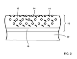
FIG. 2 is a cut view of the part and coating ofFig. 1 further including an inner and an outer coating layer - Throughout this specification the following terms have the following definitions
- "Hydrophobic" is defined as a material with a contact angle, as measured by the static sessile drop method, between a solid surface of the material and a water droplet of greater than 90 degrees.
- Siloxanes are defined as a functional group in organic silicon chemistry that has a Si-O-Si linkage. Siloxanes include polymeric hydrides, referred to as silicones or polysiloxanes that have the formulae H3-Si-[O-SiH2]n-O-SiH3 wherein hydrogen atoms may be substituted by halogens or organic groups.
- The temperature resistance of specific polysiloxanes can be varied by varying the degree of cross linking and pyrolysis/ hydrolysis in which there is a successive replacement of carbon containing end groups with oxygen to form Si02. The result is an increase in the ceramic (Si02) to organic ratio of the polysiloxane which increases the temperature resistance but typically has a detrimental effect on hydrophobicity.
-
Fig. 1 shows acoating 10 of an exemplary embodiment a ofcoating 10 that at least partially coats an axially rotatingmachine part 20 subject to water droplet impact, wherein thecoating 10 comprises ametal matrix 12 having polysiloxane distributedfiller 14. Such plants include steam turbine plants and axial flow compressors that are part of a gas turbine plant, in particular gas turbine plants that are configured with water injection means upstream of the compressor. The suitability of thecoating 10 for axial rotating machines is a result of the coating's 10 erosion resistance, temperature resilience and pH tolerance. For this reason exemplary embodiment are particular suitable for use in either steam turbines or compressors. The invention is not however limited to these machines and may alternatively be used in any high temperature moist environments where thecoating 10 is required to provide erosion protection through hardness and temperature resistance and hydrophobic properties by the incorporation of hydrophobic filler. - An effect of the
filler 14 being homogenously distributed in thecoating 10 is that this ensures that during the inevitable erosion of the coating, which occur in the aggressive environments of steam turbines and compressors in regions where moisture is present despite materials, such as like Titanium and Nickel alloys, the problem of erosion still exists. - In different exemplary embodiments, the
filler 14 may be fibrous, have a platelet, spherical or other shape. In each case, the size distribution as measured by laser diffraction, preferably is d10= 0.37 micrometres, D50=1.07 micrometres and D90 = 2.31 micrometres. The loading of themetal matrix 12 is in the range of 5 to 50 vol%, preferably in the range of 25 to 45 vol%, most preferably in the range of 35 to 45 vol%. - In an exemplary embodiment the coating includes more than one type of
filler 14, wherein the definition of type includes shape, size, material and degree of crosslinking/pyrolysis/hydrolysis. - An exemplary embodiment shown in
Fig. 2 thecoating 10 includes an erosion resistantinner layer 16 and anouter layer 12, wherein theinner layer 16 is sandwiched between theouter layer 12 and themachine part 20. A purpose of theinner layer 16 is to protect themachine part 20 in the case of erosion of theouter layer 12. - In an exemplary embodiment shown in
Fig. 3 , thefiller 14 are spherical particles, flake shaped particles, a combination of spherical and flaked shaped particles. - In an exemplary embodiment the
coating 10 may be applied to themachine part 20, or alternatively theinner layer 16, using a Electrolytic Nickel- Phosphorus coating method using a method adapted from the known electrolytic Ni-P- PTFE coating method described, for example, in "Chemisches Vernickeln", author: N. Kanani, E.G. Leuze Verlag 2007 (ISBN 978-3-87480-229-1) pg. 510-513. The method includes the process steps of chemically reducing Nickel in a reducing agent in whichfiller 14 particles are homogenously suspended with the assistance of a wetting agent. In this way,filler 14 particles are homogenously distributed within theNickel coating 10 as it is deposited on themachine part 20. - In another exemplary embodiment, the
coating 10 is be applied my means of chemical electroless Nickel plating, as is known in the art. - In a further exemplary embodiment, the
coating 10 is applied using a multi- layer principle in which layers are applied by different methods, for example either chemical electroless Nickel plating and Electrolytic Nickel coating. - In an exemplary method that can be applied a coating containing
polysiloxane filler 14 controlled stoving is used to tailor the filler temperature resistance/ hydrophobic properties. The actual stoving temperature required is not uniform but instead needs to be matched to the required end use of the coating in consideration of the presence of catalytic substances such as acids, tin and titanium compounds that affect he degree of crosslinking/ pyrolysis/hydrolysis and the actual composition and form of the polysiloxane. A particular advantage of the tailoring of polysiloxanes compared to alternative polymerichydrophobic filler 14 is that the tailoring makes it possible to produce coatings with polymeric hydrophobic fillers particles that are suitable for application where temperatures exceed 400°C or even 500°C. The method entails stoving a component have a coating containing afiller 14 of polysiloxane particles such that the temperature resistance of thefiller 14 is increased. In an exemplary embodiment, this is done after thefiller 14 is embedded into themetal matrix 12, for example, during heat treatment of themachine part 20, carried out, for example, for the purpose of improving the adhesion properties of the coating to themachine part 20. In another exemplary embodiment the stoving step is completed before embedding thefiller 14 into themetal matrix 12. This may be done, for example when the stoving step significantly changes the density of thefiller 14. In this way, any shrinkage of thefiller 14 as a result of pyrolysis occurs before it is embedded in themetal matrix 12. -
Such coatings 10 and method can advantageously be used in steam turbine coatings, in particularly low pressure steam turbines as afog rejecting coating 10 in order to lower/ avoid losses caused by condensation of steam. - The present invention has been described above purely by way of example, wherein modifications can be made within the scope of the invention. The invention may also comprise any individual features described or implicit herein or shown or implicit in the drawings or any combination of any such features or any generalisation of any such features or combination, which extends to equivalents thereof. For example, although described exemplary embodiments of the
hydrophobic filler 14 exclusively comprise polysiloxane, polysiloxane may be used in combination with other hydrophobic particles including, for example, those based on CFx. Thus, the breadth and scope of the present invention should not be limited by any of the above-described exemplary embodiments. Alternative features serving the same, equivalent or similar purposes may replace each feature disclosed in the specification, including the drawings, unless expressly stated otherwise. Unless explicitly stated herein, any discussion of the prior art throughout the specification is not an admission that such prior art is widely known or forms part of the common general knowledge in the field. -
- 10
- Coating
- 12
- Outer layer/ metal matrix
- 14
- Filler
- 16
- Inner layer
- 20
- Machine Part
Claims (14)
- A coating (10) for axially rotating machine part (20) that in use is subject to water laden gas, the coating (10) having a metal matrix (12) comprising polysiloxane filler (14) distributed throughout a thickness of the coating (10).
- The coating of claim 1 wherein the particles are homogenously distributed throughout the thickness of the coating (10).
- The coating (10) of claim 1 wherein the metal matrix (12) comprises Nickel or alloys thereof.
- The coating (10) of claim 1 wherein the filler (14) has the form of particles.
- The coating (10) of claim 6 wherein the particles have a size distribution as measured by laser diffraction of d10= 0.37 micrometres, D50=1.07 micrometres and D90 = 2.31 micrometres.
- The coating (10) of claim 1 wherein the filler (14) comprises between 5 to 50 volume % of the coating (10).
- The coating (10) of claim 1 wherein the filler (14) comprises between 25 to 45 volume % of the coating (10), more preferably between 35 to 45 volume % of the coating (10).
- The coating (10) of claim 1 comprising a corrosion resistance inner layer (16) free of the filler (14) and the metal matrix (12) forms an outer layer of the coating (10).
- The coating (10) of claim 1 wherein the part (20) is an airfoil of a steam turbine.
- The coating (10) of claim 1 wherein the part (20) is an airfoil of a gas compressor or of a gas turbine.
- A method for coating a part (20) for an axially rotating machine with an erosion resilience and coating (10), the method including the steps of:- providing a part (20) of an axially rotating machine;- coating the part (20) with a coating (10) comprising a metal matrix (12) with a polysiloxane filler(14) distributed throughout a thickness of the metal matrix (12); and- stoving the filler (14) to as to change the temperature resistance of the polysiloxane filler (14).
- The method of claim 11 wherein the stoving before the step of coating of the part (20).
- The method of claim 11 wherein the stoving step is performed after the coating step.
- The method of claim 11 wherein the method of coating includes electrolytic nickel plating and/or electroless chemical coating.
Priority Applications (3)
| Application Number | Priority Date | Filing Date | Title |
|---|---|---|---|
| EP13196979.2A EP2746428B1 (en) | 2012-12-20 | 2013-12-12 | Coating of turbine parts |
| US14/135,764 US20140178699A1 (en) | 2012-12-20 | 2013-12-20 | Coatings for turbine parts |
| US15/046,533 US10865481B2 (en) | 2012-12-20 | 2016-02-18 | Coatings for turbine parts |
Applications Claiming Priority (2)
| Application Number | Priority Date | Filing Date | Title |
|---|---|---|---|
| EP12198707 | 2012-12-20 | ||
| EP13196979.2A EP2746428B1 (en) | 2012-12-20 | 2013-12-12 | Coating of turbine parts |
Publications (2)
| Publication Number | Publication Date |
|---|---|
| EP2746428A1 true EP2746428A1 (en) | 2014-06-25 |
| EP2746428B1 EP2746428B1 (en) | 2017-09-13 |
Family
ID=47561187
Family Applications (1)
| Application Number | Title | Priority Date | Filing Date |
|---|---|---|---|
| EP13196979.2A Active EP2746428B1 (en) | 2012-12-20 | 2013-12-12 | Coating of turbine parts |
Country Status (4)
| Country | Link |
|---|---|
| US (2) | US20140178699A1 (en) |
| EP (1) | EP2746428B1 (en) |
| CN (1) | CN103879084B (en) |
| RU (1) | RU2605872C2 (en) |
Cited By (2)
| Publication number | Priority date | Publication date | Assignee | Title |
|---|---|---|---|---|
| EP2985420A1 (en) * | 2014-07-31 | 2016-02-17 | Siemens Aktiengesellschaft | Rotor blade for a steam turbine |
| WO2019103799A1 (en) * | 2017-11-21 | 2019-05-31 | Bl Technologies, Inc. | Improving steam power plant efficiency with novel steam cycle treatments |
Families Citing this family (7)
| Publication number | Priority date | Publication date | Assignee | Title |
|---|---|---|---|---|
| EP2746428B1 (en) * | 2012-12-20 | 2017-09-13 | General Electric Technology GmbH | Coating of turbine parts |
| WO2018106539A1 (en) | 2016-12-05 | 2018-06-14 | Cummins Filtration Ip, Inc. | Separation assembly with a single-piece impulse turbine |
| US11471808B2 (en) | 2017-01-09 | 2022-10-18 | Cummins Filtration Ip, Inc. | Impulse turbine with non-wetting surface for improved hydraulic efficiency |
| CN111971106B (en) | 2018-04-17 | 2022-10-28 | 康明斯过滤Ip公司 | Two-piece impingement turbine separation assembly |
| IT201900003463A1 (en) * | 2019-03-11 | 2020-09-11 | Nuovo Pignone Tecnologie Srl | Turbomachinery component having a metallic coating |
| FR3095969B1 (en) * | 2019-05-17 | 2021-04-23 | Renault Sas | Protective layer comprising phosphorus nitride and polytetrafluoroethylene, associated manufacturing process and compressor wheel provided with such a layer. |
| US11225876B2 (en) | 2019-12-19 | 2022-01-18 | Raytheon Technologies Corporation | Diffusion barrier to prevent super alloy depletion into nickel-CBN blade tip coating |
Citations (4)
| Publication number | Priority date | Publication date | Assignee | Title |
|---|---|---|---|---|
| US6623241B2 (en) * | 2000-11-14 | 2003-09-23 | Alstom (Switzerland) Ltd | Low-pressure steam turbine |
| WO2008052510A1 (en) * | 2006-11-03 | 2008-05-08 | Eads Deutschland Gmbh | Protection of erosion-stressed aerospace structures through nanoparticle-enhanced inorganic-organic hybrid coatings |
| EP2233534A1 (en) * | 2009-03-17 | 2010-09-29 | Nuovo Pignone S.p.A. | Method for producing a protective coating for a component of a turbomachine, the component itself and the respective machine |
| US20110165433A1 (en) * | 2010-01-06 | 2011-07-07 | General Electric Company | Erosion and corrosion resistant coating system for compressor |
Family Cites Families (18)
| Publication number | Priority date | Publication date | Assignee | Title |
|---|---|---|---|---|
| SU1027181A1 (en) * | 1982-04-09 | 1983-07-07 | Ленинградский Ордена Октябрьской Революции И Ордена Трудового Красного Знамени Технологический Институт Им.Ленсовета | Composition for coating metal |
| DE19644692A1 (en) | 1996-10-28 | 1998-04-30 | Abb Patent Gmbh | Coating and a process for their production |
| US6638572B1 (en) * | 2001-06-27 | 2003-10-28 | Charles F. Inglefield | Heat resistant material for molds and other articles |
| US6905730B2 (en) * | 2003-07-08 | 2005-06-14 | General Electric Company | Aluminide coating of turbine engine component |
| DK1611175T3 (en) | 2004-02-13 | 2006-07-31 | Total Petrochemicals Res Feluy | Catalyst grain size |
| US7150904B2 (en) | 2004-07-27 | 2006-12-19 | Ut-Battelle, Llc | Composite, ordered material having sharp surface features |
| US8088440B2 (en) | 2004-11-24 | 2012-01-03 | Guardian Industries Corp. | Hydrophobic coating including underlayer(s) deposited via flame pyrolysis |
| US8541103B2 (en) * | 2004-12-03 | 2013-09-24 | Kaneka Corporation | Silicone polymer particle and silicone composition containing same |
| JP4886271B2 (en) | 2005-10-31 | 2012-02-29 | 株式会社東芝 | Steam turbine and hydrophilic coating material thereof |
| EP1870485A1 (en) * | 2006-06-22 | 2007-12-26 | Siemens Aktiengesellschaft | Composition and method for metalizing a component |
| US8202614B2 (en) | 2006-08-09 | 2012-06-19 | Luna Innovations Incorporated | Additive particles having superhydrophobic characteristics and coatings and methods of making and using the same |
| DE102006044956A1 (en) | 2006-09-22 | 2008-04-03 | Reiss, Harald, Prof. Dr. Dr. habil. | Structured coating with peaks and valleys of high and low thermal conductivity, applied near gas or steam inlets to prevent agglomeration of droplets and erosion, e.g. in condenser tubes or turbine compressors |
| DE102006061916A1 (en) | 2006-12-21 | 2008-06-26 | Rolls-Royce Deutschland Ltd & Co Kg | Fan blade for a gas turbine engine |
| US20100247321A1 (en) * | 2008-01-08 | 2010-09-30 | General Electric Company | Anti-fouling coatings and articles coated therewith |
| DE102008054596B4 (en) | 2008-12-12 | 2011-04-14 | Fraunhofer-Gesellschaft zur Förderung der angewandten Forschung e.V. | Open-cell ceramic and / or metal foam bodies with a rough, enveloping surface and process for their preparation |
| IT1397705B1 (en) * | 2009-07-15 | 2013-01-24 | Nuovo Pignone Spa | PRODUCTION METHOD OF A COATING LAYER FOR A COMPONENT OF A TURBOMACCHINA, THE SAME COMPONENT AND THE RELATED MACHINE |
| DE102009047798A1 (en) | 2009-09-30 | 2011-04-14 | Siemens Aktiengesellschaft | Turbine blade, in particular end-stage blade for a steam turbine |
| EP2746428B1 (en) * | 2012-12-20 | 2017-09-13 | General Electric Technology GmbH | Coating of turbine parts |
-
2013
- 2013-12-12 EP EP13196979.2A patent/EP2746428B1/en active Active
- 2013-12-19 RU RU2013156624/02A patent/RU2605872C2/en not_active Application Discontinuation
- 2013-12-20 CN CN201310707883.5A patent/CN103879084B/en active Active
- 2013-12-20 US US14/135,764 patent/US20140178699A1/en not_active Abandoned
-
2016
- 2016-02-18 US US15/046,533 patent/US10865481B2/en active Active
Patent Citations (4)
| Publication number | Priority date | Publication date | Assignee | Title |
|---|---|---|---|---|
| US6623241B2 (en) * | 2000-11-14 | 2003-09-23 | Alstom (Switzerland) Ltd | Low-pressure steam turbine |
| WO2008052510A1 (en) * | 2006-11-03 | 2008-05-08 | Eads Deutschland Gmbh | Protection of erosion-stressed aerospace structures through nanoparticle-enhanced inorganic-organic hybrid coatings |
| EP2233534A1 (en) * | 2009-03-17 | 2010-09-29 | Nuovo Pignone S.p.A. | Method for producing a protective coating for a component of a turbomachine, the component itself and the respective machine |
| US20110165433A1 (en) * | 2010-01-06 | 2011-07-07 | General Electric Company | Erosion and corrosion resistant coating system for compressor |
Non-Patent Citations (1)
| Title |
|---|
| ADAM H WHITEHEAD ET AL: "Rain erosion characteristics of electrodeposited NiSiC metal-matrix composite layers", WEAR, ELSEVIER SEQUOIA, LAUSANNE, CH, vol. 270, no. 9, 10 February 2011 (2011-02-10), pages 695 - 702, XP028156656, ISSN: 0043-1648, [retrieved on 20110218], DOI: 10.1016/J.WEAR.2011.02.001 * |
Cited By (3)
| Publication number | Priority date | Publication date | Assignee | Title |
|---|---|---|---|---|
| EP2985420A1 (en) * | 2014-07-31 | 2016-02-17 | Siemens Aktiengesellschaft | Rotor blade for a steam turbine |
| WO2019103799A1 (en) * | 2017-11-21 | 2019-05-31 | Bl Technologies, Inc. | Improving steam power plant efficiency with novel steam cycle treatments |
| US11261762B2 (en) | 2017-11-21 | 2022-03-01 | Bl Technologies, Inc. | Improving steam power plant efficiency with novel steam cycle treatments |
Also Published As
| Publication number | Publication date |
|---|---|
| US10865481B2 (en) | 2020-12-15 |
| RU2605872C2 (en) | 2016-12-27 |
| US20140178699A1 (en) | 2014-06-26 |
| CN103879084A (en) | 2014-06-25 |
| CN103879084B (en) | 2016-03-09 |
| RU2013156624A (en) | 2015-06-27 |
| US20160160354A1 (en) | 2016-06-09 |
| EP2746428B1 (en) | 2017-09-13 |
Similar Documents
| Publication | Publication Date | Title |
|---|---|---|
| US10865481B2 (en) | Coatings for turbine parts | |
| CN108431290B (en) | Turbine clearance control coating and method | |
| US11732595B2 (en) | Abrasive tip blade manufacture methods | |
| US9260784B2 (en) | Blade tip coating that can be rubbed off | |
| EP2196632A2 (en) | A seal in a gas turbine and a method of manufacturing a seal | |
| EP1780379A2 (en) | Steam turbine and hydrophilic coating material used therefor | |
| US20140272166A1 (en) | Coating system for improved leading edge erosion protection | |
| US11125102B2 (en) | Chemistry based methods of manufacture for MAXMET composite powders | |
| US20200025016A1 (en) | Coating to improve oxidation and corrosion resistance of abrasive tip system | |
| EP2821525A1 (en) | Multilayered coatings with diamond like carbon | |
| JP6313762B2 (en) | Abrasive coatings made of materials with low surface roughness | |
| EP2969260B1 (en) | Anti-fret coating system | |
| EP3611350B1 (en) | Turbine abrasive blade tips with improved resistance to oxidation | |
| EP3360985B1 (en) | Multilayer abradable coating | |
| JP6077104B2 (en) | Turbomachine parts with functional coating | |
| US20130084399A1 (en) | Coating composition, a process of applying a coating, and a process of forming a coating composition | |
| US20240158921A1 (en) | Coating composition, coated turbine component, and method of applying the coating | |
| CN114174548A (en) | Abradable coating | |
| CN115011845A (en) | Anti-fretting coating composition and coated part | |
| JP2018535322A (en) | Turbine clearance control coating and method |
Legal Events
| Date | Code | Title | Description |
|---|---|---|---|
| PUAI | Public reference made under article 153(3) epc to a published international application that has entered the european phase |
Free format text: ORIGINAL CODE: 0009012 |
|
| 17P | Request for examination filed |
Effective date: 20131212 |
|
| AK | Designated contracting states |
Kind code of ref document: A1 Designated state(s): AL AT BE BG CH CY CZ DE DK EE ES FI FR GB GR HR HU IE IS IT LI LT LU LV MC MK MT NL NO PL PT RO RS SE SI SK SM TR |
|
| AX | Request for extension of the european patent |
Extension state: BA ME |
|
| 17Q | First examination report despatched |
Effective date: 20160617 |
|
| RAP1 | Party data changed (applicant data changed or rights of an application transferred) |
Owner name: GENERAL ELECTRIC TECHNOLOGY GMBH |
|
| GRAP | Despatch of communication of intention to grant a patent |
Free format text: ORIGINAL CODE: EPIDOSNIGR1 |
|
| RIC1 | Information provided on ipc code assigned before grant |
Ipc: C23C 18/16 20060101ALI20170324BHEP Ipc: C25D 5/50 20060101ALI20170324BHEP Ipc: C25D 15/00 20060101ALI20170324BHEP Ipc: F04D 29/02 20060101ALI20170324BHEP Ipc: F01D 5/28 20060101ALI20170324BHEP Ipc: C23C 28/02 20060101ALI20170324BHEP Ipc: C23C 30/00 20060101AFI20170324BHEP Ipc: C23C 18/36 20060101ALI20170324BHEP |
|
| INTG | Intention to grant announced |
Effective date: 20170418 |
|
| GRAS | Grant fee paid |
Free format text: ORIGINAL CODE: EPIDOSNIGR3 |
|
| GRAA | (expected) grant |
Free format text: ORIGINAL CODE: 0009210 |
|
| AK | Designated contracting states |
Kind code of ref document: B1 Designated state(s): AL AT BE BG CH CY CZ DE DK EE ES FI FR GB GR HR HU IE IS IT LI LT LU LV MC MK MT NL NO PL PT RO RS SE SI SK SM TR |
|
| REG | Reference to a national code |
Ref country code: GB Ref legal event code: FG4D |
|
| REG | Reference to a national code |
Ref country code: CH Ref legal event code: EP |
|
| REG | Reference to a national code |
Ref country code: IE Ref legal event code: FG4D |
|
| REG | Reference to a national code |
Ref country code: AT Ref legal event code: REF Ref document number: 928218 Country of ref document: AT Kind code of ref document: T Effective date: 20171015 |
|
| REG | Reference to a national code |
Ref country code: DE Ref legal event code: R096 Ref document number: 602013026486 Country of ref document: DE |
|
| REG | Reference to a national code |
Ref country code: NL Ref legal event code: MP Effective date: 20170913 |
|
| REG | Reference to a national code |
Ref country code: LT Ref legal event code: MG4D |
|
| PG25 | Lapsed in a contracting state [announced via postgrant information from national office to epo] |
Ref country code: NO Free format text: LAPSE BECAUSE OF FAILURE TO SUBMIT A TRANSLATION OF THE DESCRIPTION OR TO PAY THE FEE WITHIN THE PRESCRIBED TIME-LIMIT Effective date: 20171213 Ref country code: SE Free format text: LAPSE BECAUSE OF FAILURE TO SUBMIT A TRANSLATION OF THE DESCRIPTION OR TO PAY THE FEE WITHIN THE PRESCRIBED TIME-LIMIT Effective date: 20170913 Ref country code: FI Free format text: LAPSE BECAUSE OF FAILURE TO SUBMIT A TRANSLATION OF THE DESCRIPTION OR TO PAY THE FEE WITHIN THE PRESCRIBED TIME-LIMIT Effective date: 20170913 Ref country code: HR Free format text: LAPSE BECAUSE OF FAILURE TO SUBMIT A TRANSLATION OF THE DESCRIPTION OR TO PAY THE FEE WITHIN THE PRESCRIBED TIME-LIMIT Effective date: 20170913 Ref country code: LT Free format text: LAPSE BECAUSE OF FAILURE TO SUBMIT A TRANSLATION OF THE DESCRIPTION OR TO PAY THE FEE WITHIN THE PRESCRIBED TIME-LIMIT Effective date: 20170913 |
|
| REG | Reference to a national code |
Ref country code: AT Ref legal event code: MK05 Ref document number: 928218 Country of ref document: AT Kind code of ref document: T Effective date: 20170913 |
|
| PG25 | Lapsed in a contracting state [announced via postgrant information from national office to epo] |
Ref country code: BG Free format text: LAPSE BECAUSE OF FAILURE TO SUBMIT A TRANSLATION OF THE DESCRIPTION OR TO PAY THE FEE WITHIN THE PRESCRIBED TIME-LIMIT Effective date: 20171213 Ref country code: RS Free format text: LAPSE BECAUSE OF FAILURE TO SUBMIT A TRANSLATION OF THE DESCRIPTION OR TO PAY THE FEE WITHIN THE PRESCRIBED TIME-LIMIT Effective date: 20170913 Ref country code: ES Free format text: LAPSE BECAUSE OF FAILURE TO SUBMIT A TRANSLATION OF THE DESCRIPTION OR TO PAY THE FEE WITHIN THE PRESCRIBED TIME-LIMIT Effective date: 20170913 Ref country code: GR Free format text: LAPSE BECAUSE OF FAILURE TO SUBMIT A TRANSLATION OF THE DESCRIPTION OR TO PAY THE FEE WITHIN THE PRESCRIBED TIME-LIMIT Effective date: 20171214 Ref country code: LV Free format text: LAPSE BECAUSE OF FAILURE TO SUBMIT A TRANSLATION OF THE DESCRIPTION OR TO PAY THE FEE WITHIN THE PRESCRIBED TIME-LIMIT Effective date: 20170913 |
|
| PG25 | Lapsed in a contracting state [announced via postgrant information from national office to epo] |
Ref country code: NL Free format text: LAPSE BECAUSE OF FAILURE TO SUBMIT A TRANSLATION OF THE DESCRIPTION OR TO PAY THE FEE WITHIN THE PRESCRIBED TIME-LIMIT Effective date: 20170913 |
|
| PG25 | Lapsed in a contracting state [announced via postgrant information from national office to epo] |
Ref country code: PL Free format text: LAPSE BECAUSE OF FAILURE TO SUBMIT A TRANSLATION OF THE DESCRIPTION OR TO PAY THE FEE WITHIN THE PRESCRIBED TIME-LIMIT Effective date: 20170913 Ref country code: RO Free format text: LAPSE BECAUSE OF FAILURE TO SUBMIT A TRANSLATION OF THE DESCRIPTION OR TO PAY THE FEE WITHIN THE PRESCRIBED TIME-LIMIT Effective date: 20170913 Ref country code: CZ Free format text: LAPSE BECAUSE OF FAILURE TO SUBMIT A TRANSLATION OF THE DESCRIPTION OR TO PAY THE FEE WITHIN THE PRESCRIBED TIME-LIMIT Effective date: 20170913 |
|
| PG25 | Lapsed in a contracting state [announced via postgrant information from national office to epo] |
Ref country code: AT Free format text: LAPSE BECAUSE OF FAILURE TO SUBMIT A TRANSLATION OF THE DESCRIPTION OR TO PAY THE FEE WITHIN THE PRESCRIBED TIME-LIMIT Effective date: 20170913 Ref country code: SM Free format text: LAPSE BECAUSE OF FAILURE TO SUBMIT A TRANSLATION OF THE DESCRIPTION OR TO PAY THE FEE WITHIN THE PRESCRIBED TIME-LIMIT Effective date: 20170913 Ref country code: IS Free format text: LAPSE BECAUSE OF FAILURE TO SUBMIT A TRANSLATION OF THE DESCRIPTION OR TO PAY THE FEE WITHIN THE PRESCRIBED TIME-LIMIT Effective date: 20180113 Ref country code: EE Free format text: LAPSE BECAUSE OF FAILURE TO SUBMIT A TRANSLATION OF THE DESCRIPTION OR TO PAY THE FEE WITHIN THE PRESCRIBED TIME-LIMIT Effective date: 20170913 Ref country code: SK Free format text: LAPSE BECAUSE OF FAILURE TO SUBMIT A TRANSLATION OF THE DESCRIPTION OR TO PAY THE FEE WITHIN THE PRESCRIBED TIME-LIMIT Effective date: 20170913 |
|
| REG | Reference to a national code |
Ref country code: DE Ref legal event code: R097 Ref document number: 602013026486 Country of ref document: DE |
|
| PLBE | No opposition filed within time limit |
Free format text: ORIGINAL CODE: 0009261 |
|
| STAA | Information on the status of an ep patent application or granted ep patent |
Free format text: STATUS: NO OPPOSITION FILED WITHIN TIME LIMIT |
|
| PG25 | Lapsed in a contracting state [announced via postgrant information from national office to epo] |
Ref country code: DK Free format text: LAPSE BECAUSE OF FAILURE TO SUBMIT A TRANSLATION OF THE DESCRIPTION OR TO PAY THE FEE WITHIN THE PRESCRIBED TIME-LIMIT Effective date: 20170913 |
|
| REG | Reference to a national code |
Ref country code: CH Ref legal event code: PL |
|
| 26N | No opposition filed |
Effective date: 20180614 |
|
| REG | Reference to a national code |
Ref country code: IE Ref legal event code: MM4A |
|
| PG25 | Lapsed in a contracting state [announced via postgrant information from national office to epo] |
Ref country code: LU Free format text: LAPSE BECAUSE OF NON-PAYMENT OF DUE FEES Effective date: 20171212 Ref country code: MT Free format text: LAPSE BECAUSE OF NON-PAYMENT OF DUE FEES Effective date: 20171212 |
|
| REG | Reference to a national code |
Ref country code: FR Ref legal event code: ST Effective date: 20180831 |
|
| REG | Reference to a national code |
Ref country code: BE Ref legal event code: MM Effective date: 20171231 |
|
| PG25 | Lapsed in a contracting state [announced via postgrant information from national office to epo] |
Ref country code: IE Free format text: LAPSE BECAUSE OF NON-PAYMENT OF DUE FEES Effective date: 20171212 Ref country code: FR Free format text: LAPSE BECAUSE OF NON-PAYMENT OF DUE FEES Effective date: 20180102 |
|
| PG25 | Lapsed in a contracting state [announced via postgrant information from national office to epo] |
Ref country code: LI Free format text: LAPSE BECAUSE OF NON-PAYMENT OF DUE FEES Effective date: 20171231 Ref country code: SI Free format text: LAPSE BECAUSE OF FAILURE TO SUBMIT A TRANSLATION OF THE DESCRIPTION OR TO PAY THE FEE WITHIN THE PRESCRIBED TIME-LIMIT Effective date: 20170913 Ref country code: BE Free format text: LAPSE BECAUSE OF NON-PAYMENT OF DUE FEES Effective date: 20171231 Ref country code: CH Free format text: LAPSE BECAUSE OF NON-PAYMENT OF DUE FEES Effective date: 20171231 |
|
| PG25 | Lapsed in a contracting state [announced via postgrant information from national office to epo] |
Ref country code: MC Free format text: LAPSE BECAUSE OF FAILURE TO SUBMIT A TRANSLATION OF THE DESCRIPTION OR TO PAY THE FEE WITHIN THE PRESCRIBED TIME-LIMIT Effective date: 20170913 Ref country code: HU Free format text: LAPSE BECAUSE OF FAILURE TO SUBMIT A TRANSLATION OF THE DESCRIPTION OR TO PAY THE FEE WITHIN THE PRESCRIBED TIME-LIMIT; INVALID AB INITIO Effective date: 20131212 |
|
| PG25 | Lapsed in a contracting state [announced via postgrant information from national office to epo] |
Ref country code: CY Free format text: LAPSE BECAUSE OF NON-PAYMENT OF DUE FEES Effective date: 20170913 |
|
| PG25 | Lapsed in a contracting state [announced via postgrant information from national office to epo] |
Ref country code: MK Free format text: LAPSE BECAUSE OF FAILURE TO SUBMIT A TRANSLATION OF THE DESCRIPTION OR TO PAY THE FEE WITHIN THE PRESCRIBED TIME-LIMIT Effective date: 20170913 |
|
| PG25 | Lapsed in a contracting state [announced via postgrant information from national office to epo] |
Ref country code: TR Free format text: LAPSE BECAUSE OF FAILURE TO SUBMIT A TRANSLATION OF THE DESCRIPTION OR TO PAY THE FEE WITHIN THE PRESCRIBED TIME-LIMIT Effective date: 20170913 |
|
| PG25 | Lapsed in a contracting state [announced via postgrant information from national office to epo] |
Ref country code: PT Free format text: LAPSE BECAUSE OF FAILURE TO SUBMIT A TRANSLATION OF THE DESCRIPTION OR TO PAY THE FEE WITHIN THE PRESCRIBED TIME-LIMIT Effective date: 20170913 |
|
| PG25 | Lapsed in a contracting state [announced via postgrant information from national office to epo] |
Ref country code: AL Free format text: LAPSE BECAUSE OF FAILURE TO SUBMIT A TRANSLATION OF THE DESCRIPTION OR TO PAY THE FEE WITHIN THE PRESCRIBED TIME-LIMIT Effective date: 20170913 |
|
| PGFP | Annual fee paid to national office [announced via postgrant information from national office to epo] |
Ref country code: GB Payment date: 20201123 Year of fee payment: 8 |
|
| GBPC | Gb: european patent ceased through non-payment of renewal fee |
Effective date: 20211212 |
|
| PG25 | Lapsed in a contracting state [announced via postgrant information from national office to epo] |
Ref country code: GB Free format text: LAPSE BECAUSE OF NON-PAYMENT OF DUE FEES Effective date: 20211212 |
|
| PGFP | Annual fee paid to national office [announced via postgrant information from national office to epo] |
Ref country code: IT Payment date: 20221122 Year of fee payment: 10 |
|
| PGFP | Annual fee paid to national office [announced via postgrant information from national office to epo] |
Ref country code: DE Payment date: 20231121 Year of fee payment: 11 |