EP2746000A1 - Robot system, robot, and robot control device - Google Patents
Robot system, robot, and robot control device Download PDFInfo
- Publication number
- EP2746000A1 EP2746000A1 EP20110871270 EP11871270A EP2746000A1 EP 2746000 A1 EP2746000 A1 EP 2746000A1 EP 20110871270 EP20110871270 EP 20110871270 EP 11871270 A EP11871270 A EP 11871270A EP 2746000 A1 EP2746000 A1 EP 2746000A1
- Authority
- EP
- European Patent Office
- Prior art keywords
- calculation unit
- robot
- links
- retracting direction
- torque
- Prior art date
- Legal status (The legal status is an assumption and is not a legal conclusion. Google has not performed a legal analysis and makes no representation as to the accuracy of the status listed.)
- Withdrawn
Links
Images



Classifications
-
- B—PERFORMING OPERATIONS; TRANSPORTING
- B25—HAND TOOLS; PORTABLE POWER-DRIVEN TOOLS; MANIPULATORS
- B25J—MANIPULATORS; CHAMBERS PROVIDED WITH MANIPULATION DEVICES
- B25J9/00—Program-controlled manipulators
- B25J9/16—Program controls
- B25J9/1628—Program controls characterised by the control loop
- B25J9/1633—Program controls characterised by the control loop compliant, force, torque control, e.g. combined with position control
-
- B—PERFORMING OPERATIONS; TRANSPORTING
- B25—HAND TOOLS; PORTABLE POWER-DRIVEN TOOLS; MANIPULATORS
- B25J—MANIPULATORS; CHAMBERS PROVIDED WITH MANIPULATION DEVICES
- B25J13/00—Controls for manipulators
- B25J13/08—Controls for manipulators by means of sensing devices, e.g. viewing or touching devices
- B25J13/081—Touching devices, e.g. pressure-sensitive
-
- B—PERFORMING OPERATIONS; TRANSPORTING
- B25—HAND TOOLS; PORTABLE POWER-DRIVEN TOOLS; MANIPULATORS
- B25J—MANIPULATORS; CHAMBERS PROVIDED WITH MANIPULATION DEVICES
- B25J9/00—Program-controlled manipulators
- B25J9/16—Program controls
- B25J9/1674—Program controls characterised by safety, monitoring, diagnostic
- B25J9/1676—Avoiding collision or forbidden zones
-
- G—PHYSICS
- G05—CONTROLLING; REGULATING
- G05B—CONTROL OR REGULATING SYSTEMS IN GENERAL; FUNCTIONAL ELEMENTS OF SUCH SYSTEMS; MONITORING OR TESTING ARRANGEMENTS FOR SUCH SYSTEMS OR ELEMENTS
- G05B2219/00—Program-control systems
- G05B2219/30—Nc systems
- G05B2219/39—Robotics, robotics to robotics hand
- G05B2219/39183—Compliance compensation
-
- G—PHYSICS
- G05—CONTROLLING; REGULATING
- G05B—CONTROL OR REGULATING SYSTEMS IN GENERAL; FUNCTIONAL ELEMENTS OF SUCH SYSTEMS; MONITORING OR TESTING ARRANGEMENTS FOR SUCH SYSTEMS OR ELEMENTS
- G05B2219/00—Program-control systems
- G05B2219/30—Nc systems
- G05B2219/40—Robotics, robotics mapping to robotics vision
- G05B2219/40219—Detect contact, proximity of other manipulators
Definitions
- the embodiments discussed herein are directed to a robot system, a robot, and a robot control device.
- Patent Literature 1 describes a control system for a robot. During a moving operation of a robot each of whose axes is driven by a servo motor controlled in a control system including a position control loop and a speed control loop, this control system for a robot detects whether the robot or an object supported by the robot touches an external object, and if contact is detected, adjusts gains of the position control loop and the speed control loop downward.
- Patent Literature 1 Japanese Patent No. 3300625
- a robot system includes a robot and a robot control device that controls the robot.
- the robot includes a plurality of links connected via a plurality of joint axes, servo motors that drive the joint axes, and a contact detection sensor that detects that one of the links touches an object.
- the robot control device includes a contact position determination unit, a retracting direction vector calculation unit, an assist torque calculation unit, and a flexible control unit.
- the contact position determination unit determines a contact position on the link with the object on the basis of an output from the contact detection sensor.
- the retracting direction vector calculation unit calculates a retracting direction vector in a retracting direction of the link corresponding to the contact position determined by the contact position determination unit.
- the assist torque calculation unit calculates assist torque references that are torque references for the servo motors for moving the links in the direction of the retracting direction vector.
- the flexible control unit adds the assist torque references to torque references for the servo motors to flexibly control the links.
- a robot system includes a robot and a robot control device that controls the robot.
- the robot includes a plurality of links connected via a plurality of joint axes, servo motors that drive the joint axes, and a contact detection sensor that detects that one of the links touches an object.
- the robot control device includes a contact position determination unit, a retracting direction vector calculation unit, an assist torque calculation unit, and a flexible control unit.
- the contact position determination unit determines a contact position on the link with the object on the basis of an output from the contact detection sensor.
- the retracting direction vector calculation unit includes a contact portion normal vector calculation unit, a contact point movement vector calculation unit, and a retracting direction vector correction unit.
- the contact portion normal vector calculation unit calculates a retracting direction vector in a retracting direction of the link corresponding to the contact position determined by the contact position determination unit.
- the contact point movement vector calculation unit calculates a movement vector representing a direction of actual movement of the contact position determined by the contact position determination unit.
- the retracting direction vector correction unit corrects the retracting direction vector on the basis of the movement vector.
- the assist torque calculation unit calculates assist torque references that are torque references for the servo motors for moving the links in the direction of the retracting direction vector corrected by the retracting direction vector calculation unit.
- the flexible control unit adds the assist torque references to torque references for the servo motors to flexibly control the links.
- a robot includes a plurality of links connected via a plurality of joint axes, and servo motors that drive the joint axes.
- Each of the links includes a plurality of contact detection sensors that are provided side by side along an outer circumferential direction of the corresponding link to detect that the corresponding link touches an object.
- a robot control device includes a contact position determination unit, a retracting direction vector calculation unit, an assist torque calculation unit, and a flexible control unit.
- the contact position determination unit determines, when one of links of a robot driven by a plurality of servo motors touches an object, a contact position on the link.
- the retracting direction vector calculation unit calculates a retracting direction vector in a retracting direction of the link corresponding to the contact position.
- the assist torque calculation unit calculates assist torque references that are torque references for the servo motors for moving the links in the direction of the retracting direction vector.
- the flexible control unit adds the assist torque references to torque references for the servo motors to flexibly control the links.
- a robot control device includes a contact position determination unit, a retracting direction vector calculation unit, an assist torque calculation unit, and a flexible control unit.
- the contact position determination unit determines, when one of links of a robot driven by a plurality of servo motors touches an object, a contact position on the link.
- the retracting direction vector calculation unit includes a contact portion normal vector calculation unit, a contact point movement vector calculation unit, and a retracting direction vector correction unit.
- the contact portion normal vector calculation unit calculates a retracting direction vector in a retracting direction of the link corresponding to the contact position determined by the contact position determination unit.
- the contact point movement vector calculation unit calculates a movement vector representing a direction of actual movement of the contact position determined by the contact position determination unit.
- the retracting direction vector correction unit corrects the retracting direction vector on the basis of the movement vector.
- the assist torque calculation unit calculates assist torque references that are torque references for the servo motors for moving the links in the direction of the retracting direction vector corrected by the retracting direction vector calculation unit.
- the flexible control unit adds the assist torque references to torque references for the servo motors to flexibly control the links.
- joint axes of links that touch an object can operate more flexibly than in the case of not having a configuration of the embodiments.
- a robot system 10 includes a robot 12 and a robot control device 14 that controls the operation of the robot 12.
- the robot 12 includes, for example, a moving unit 22 for moving on a floor surface, a body 24 that is provided on top of the moving unit 22 with a joint axis AXW therebetween and rotates in fore and aft directions about the joint axis AXW serving as the center of rotation, and arms 26 provided on both sides of the body 24.
- the robot control device 14 may be embedded in the robot 12.
- each of the arms 26 includes a plurality of links 28 connected with a plurality of joint axes AX therebetween.
- Each of the joint axes AX is driven by a servo motor SVM (refer to FIG. 4 ) including an encoder ENC.
- each of the links 28 of the arms 26 of the robot 12 is provided with, for example, a total of eight rectangular contact sensors 30.
- the contact sensors 30 are provided inside an outer skin 32 covering the link 28.
- the outer skin 32 moderates the impact force applied when the link 28 touches an object, and thus can protect the contact sensors 30.
- Each of the contact sensors 30 can output on/off signals according to the state of contact with the object.
- the contact sensor 30 can output the on signal when the object is in contact with the link 28, and can output the off signal when the object is apart from the link 28.
- the contact sensors 30 are pasted side by side along the outer circumferential direction of the link 28. Specifically, the outer circumference of the link 28 is divided into eight regions, and the contact sensor 30 is pasted in each of the regions. This allows a position on the link 28 touched by the object to be identified at a resolution of 45 degrees with respect to an angular position about the longitudinal axis AXL of the link 28 illustrated in FIG. 2 .
- the total number of the contact sensors 30 is not limited to eight.
- the contact sensors 30 need not be provided side by side along the outer circumferential direction of the link 28.
- the area for detection of contact with the object may be divided into 16 regions in the circumferential direction of the link 28, and the contact sensor 30 may be provided in each of the regions.
- the area for detection of contact with the object may be divided into eight in the circumferential direction and two in the longitudinal direction of the link 28, thus being divided into a total of 16 regions, and the contact sensor 30 may be provided in each of the regions.
- the contact sensor 30 is not limited to the contact sensor that outputs the on/off signals.
- Other examples of the contact sensor include a sensor that adjusts the level of an output signal thereof according to the magnitude of the contact force (contact pressure) applied thereto.
- These contact sensors 30 constitute an example of a contact detection sensor that can detect the contact of the link 28 with the object.
- the contact detection sensor only needs to be capable of detecting the position or an area including the position on the link 28 touched by the object.
- the robot control device 14 includes a reference generating unit 42, a sensor signal input unit 44, a contact position determination unit 46, a first retracting direction vector calculation unit 48, an assist torque calculation unit 50, and a flexible control unit 52 that outputs torque references ⁇ ref to servo amplifiers SVA connected to the respective servo motors SVM.
- the robot control device 14 has an embedded CPU and memory (not illustrated). The blocks illustrated in FIG. 4 are implemented by a software program executed by the CPU and hardware.
- FIG. 4 collectively represents the contact sensors 30, the servo motors SVM, the encoders ENC, and the servo amplifiers SVA as respective single blocks.
- the reference generating unit 42 can generate position references Pref to the servo motors SVM for rotationally moving the links 28 of the robot 12 to move a tip of the arms 26.
- the generated position references Pref are entered into the flexible control unit 52.
- the contact sensors 30 are connected to the sensor signal input unit 44.
- the sensor signal input unit 44 functions as an interface for the contact sensors 30.
- the sensor signal input unit 44 outputs signals corresponding to the on/off signals of the contact sensors 30. These signals are entered into the reference generating unit 42.
- the contact position determination unit 46 can determine the position on the link 28 touched by the object as a contact position Pc.
- the on/off signals output by the contact sensors 30 are entered into the contact position determination unit 46 via the sensor signal input unit 44.
- the contact position determination unit 46 detects the on signal output by any one of the eight contact sensors 30, and thus identifies the contact sensor 30 touched by the object.
- the contact position determination unit 46 can obtain a predetermined point corresponding to the contact sensor 30 as the contact position Pc illustrated in FIG. 3 .
- the contact position Pc is predetermined, for example, as a center position of a surface of each of the contact sensors 30.
- the contact position Pc is not limited to the center position of the surface of the contact sensor 30, but may be any position that corresponds to the contact sensor 30.
- the position on the link 28 actually touched by the object may differ from the contact position Pc obtained by the contact position determination unit 46, as illustrated in FIG. 3 .
- increasing the number of the divided regions on which the contact sensors are pasted brings the position on the link 28 actually touched by the object into closer agreement with the contact position Pc.
- providing a sensor also outputting a contact position instead of the contact sensor 30 brings the position on the link 28 actually touched by the object into substantial agreement with the contact position Pc.
- the contact position Pc is calculated, for example, as a position in a robot coordinate system fixed to the body 24 of the robot 12.
- the contact position determination unit 46 may be configured to detect a plurality of contact positions. That case allows the contact position determination unit 46 to output a plurality of calculated contact positions.
- the first retracting direction vector calculation unit 48 illustrated in FIG. 4 can calculate the direction of movement (retracting direction) of the link 28 as a retracting direction vector n.
- the retracting direction vector n is predetermined, and is, for example, a unit vector in the normal direction of a surface of the link 28 in the contact position Pc. Therefore, the direction of the retracting direction vector n may differ from the direction of the external force fc received from the object in contact with the link 28 as illustrated in FIG. 3 .
- the retracting direction vector n is calculated as a vector in the robot coordinate system by using the above-described coordinate transformation matrix T.
- the assist torque calculation unit 50 illustrated in FIG. 4 can calculate an assist torque reference ⁇ a for each of the joint axes AX of the robot 12.
- the assist torque calculation unit 50 includes an assist force determination unit 50a, an assist force vector calculation unit 50b, and a torque calculation unit 50c.
- the assist force determination unit 50a can determine the magnitude of the assist force f for retracting the links 28 (arm 26), and can output the assist force f as a scalar quantity. Changing the assist force f depending on the situation can adjust flexibility of the joint axes AX of the arm 26 included in the robot 12.
- the assist force determination unit 50a can output the assist force f having a larger first magnitude after the link 28 touches the object until a predetermined time tim (such as 1 to 10 milliseconds) passes, and can output the assist force f having a second magnitude smaller than the first magnitude after the time tim has passed. In this manner, after the link 28 touches the object, the assist force determination unit 50a first outputs the assist force f having the larger first magnitude so as to quickly move the link 28 in the retracting direction, thus suppressing the contact force (impact force).
- a predetermined time tim such as 1 to 10 milliseconds
- the assist force determination unit 50a may determine the assist force f based on the level of this signal.
- the torque calculation unit 50c can obtain a Jacobian transpose J T in the calculated contact position from the calculated contact position calculated by the contact position determination unit 46, and can calculate the assist torque reference ⁇ a for the servo motor SVM driving each of the joint axes AX using the following equation.
- the assist torque reference ⁇ a is a torque reference for each of the joint axes AX for moving the link 28 in the direction of the retracting direction vector.
- ⁇ a J T ⁇ Fa
- the assist torque calculation unit may be an assist torque calculation unit 50x that further includes a weight calculation unit 50d between the assist force vector calculation unit 50b and the torque calculation unit 50c, as illustrated in FIG. 6 .
- the weight calculation unit 50d can multiply the assist force vector Fa output from the assist force vector calculation unit 50b of the preceding block by a weighting factor matrix k, and can output the result to the torque calculation unit 50c of the subsequent block.
- the weighting factor matrix k is a diagonal matrix for adjusting the magnitude of assist torque (torque for moving the link 28 in the direction of the retracting direction vector) to be generated by each of the joint axes AX of the link 28.
- the weighting factor matrix k is set, for example, as follows.
- the weighting factor matrix k is set according to amounts of coefficients of viscous friction of reduction gears, etc. provided at the joint axes AX. Specifically, the weighting factor matrix k is set so as to increase the assist torque reference for the servo motor SVM driving each of the joint axes AX according to the amount of the coefficient of viscous friction of the joint axis AX. In other words, the weighting factor matrix k performs weighting so as to give the joint axis AX having a larger coefficient of viscous friction a larger magnitude of assist torque.
- the weighting factor matrix k performs weighting so as to give the largest magnitude of assist torque to the joint axis AX located at the root (base end) of the link 28 that touches the object. More specifically, the weighting factor matrix k performs weighting so as to give a larger magnitude of assist torque to the joint axis AX nearer to the contact position Pc on the link 28 that touches the object, among all of the joint axes AX located on the side nearer to the root (base end) of the arm 26 than the contact position Pc.
- the flexible control unit 52 illustrated in FIG. 4 can output the torque references ⁇ ref for driving the servo motors SVM to the servo amplifiers SVA, and thus can perform control so as to flexibly operate the joint axes AX of the robot 12.
- the flexible control unit 52 includes a position/speed control unit 52a, a torque limit value calculation unit 52b, a torque limiting unit 52c, and a gravity compensation torque calculation unit 52d.
- Position/speed control loops are formed in the position/speed control unit 52a.
- the position/speed control unit 52a can output a torque reference ⁇ b according to a position error e between an angle feedback (encoder value) Pfb of each of the servo motors SVM obtained from the encoders ENC and the position reference Pref generated by the reference generating unit 42.
- the torque limit value calculation unit 52b can obtain a torque limit value Tlim.
- the torque limit value calculation unit 52b can obtain the torque limit value (upper or lower limit value) Tlim, for example, so as to include therebetween torque of the servo motor SVM required for motion of the links 28 (torque for accelerating both the links 28 and a tip load of the arm 26, and torque for maintaining movement velocities of the links 28).
- the torque limit value calculation unit 52b can obtain a predetermined maximum torque value of the servo motor SVM as the torque limit value Tlim.
- the torque limiting unit 52c can limit the torque reference ⁇ b output by the position/speed control unit 52a with the torque limit value Tlim calculated by the torque limit value calculation unit 52b, and thus can output a limited torque reference ⁇ lim.
- the gravity compensation torque calculation unit 52d can calculate torque by gravity of each of the joint axes AX as gravity compensation torque ⁇ g by calculation of dynamics based on the encoder value Pfb of each of the servo motors SVM.
- the calculated gravity compensation torque ⁇ g is added together with the assist torque reference ⁇ a to the torque reference ⁇ lim output by the torque limiting unit 52c.
- the position/speed control unit 52a of the flexible control unit 52 outputs the torque reference ⁇ b based on the position reference Pref generated by the reference generating unit 42. If the torque reference ⁇ b exceeds the torque limit value Tlim, the torque limiting unit 52c limits the magnitude of the torque reference and outputs it as the torque reference ⁇ lim (refer to FIG. 7 ).
- the assist torque calculation unit 50 does not output the assist torque reference ⁇ a because each of the contact sensors 30 does not output the on signal. In other words, the magnitude of the assist torque reference ⁇ a is zero.
- the gravity compensation torque calculation unit 52d outputs the gravity compensation torque ⁇ g based on the encoder value Pfb.
- the gravity compensation torque ⁇ g calculated by the gravity compensation torque calculation unit 52d is added to the torque reference ⁇ lim, and the torque reference ⁇ ref is output to the servo amplifier SVA (refer to FIG. 4 ).
- each of the servo motors SVM is driven according to the torque reference ⁇ ref, and the arm 26 of the robot 12 operates.
- the operation of the robot system 10 differs depending on whether the arm 26 is retracted from the touched object or moves following the external force fc received from the touched object. The operation will be described below for separate cases.
- the reference generating unit 42 Based on the signal output by the sensor signal input unit 44, the reference generating unit 42 stops outputting the position reference Pref.
- the position/speed control unit 52a of the flexible control unit 52 outputs the torque reference ⁇ b according to the position error e.
- the torque limit value calculation unit 52b determines that the output of the position reference Pref has been stopped, and sets the torque limit value Tlim to zero. It follows that the torque limiting unit 52c sets the torque reference ⁇ lim to zero regardless of the torque reference ⁇ b.
- the assist torque calculation unit 50 outputs the assist torque reference ⁇ a according to the contact position Pc.
- the gravity compensation torque calculation unit 52d outputs the gravity compensation torque ⁇ g based on the encoder value Pfb.
- the assist torque reference ⁇ a and the gravity compensation torque ⁇ g are added to the torque reference ⁇ lim at the block subsequent to the torque limiting unit 52c, and the result is output as the torque reference ⁇ ref.
- each of the servo motors SVM is driven according to the torque reference ⁇ ref, and the links 28 are retracted by the assist torque from the touched object.
- the reference generating unit 42 continues outputting the position reference Pref.
- the position/speed control unit 52a of the flexible control unit 52 outputs the torque reference ⁇ b based on the position reference Pref generated by the reference generating unit 42. If the torque reference ⁇ b output by the position/speed control unit 52a exceeds the torque limit value Tlim, the torque limiting unit 52c limits the magnitude of the torque reference and outputs it as the torque reference ⁇ lim.
- the assist torque calculation unit 50 outputs the assist torque reference ⁇ a according to the contact position Pc.
- the gravity compensation torque calculation unit 52d outputs the gravity compensation torque ⁇ g based on the encoder value Pfb.
- the assist torque reference ⁇ a and the gravity compensation torque ⁇ g are added to the torque reference ⁇ lim output by the torque limiting unit 52c, and the torque reference ⁇ ref is output.
- the addition of the assist torque reference ⁇ a to the torque reference ⁇ ref causes the joint axes AX of the arm 26 to flexibly operate in the direction of following the external force fc.
- the addition of the assist torque allows the robot system 10 according to the present embodiment to flexibly operate the joint axes AX of the arm 26.
- an impact applied to the object touching the link 28 can be suppressed.
- a robot control device 114 of the robot system includes a second retracting direction vector calculation unit 148, instead of the first retracting direction vector calculation unit 48.
- the second retracting direction vector calculation unit 148 includes a contact portion normal vector calculation unit 148a that can calculate the retracting direction vector n (refer to FIG. 10 ), a contact point movement vector calculation unit 148b that can calculate a movement vector m, and a retracting direction vector correction unit 148c that can correct the retracting direction vector n based on the movement vector m.
- the contact portion normal vector calculation unit 148a can calculate the direction of movement of the link 28 as the retracting direction vector n.
- the retracting direction vector n is predetermined, and is, for example, a unit vector in the normal direction of the surface of the link 28 in the contact position.
- the contact point movement vector calculation unit 148b can calculate a vector representing the direction of actual movement of the contact position Pc as the movement vector m.
- the retracting direction vector correction unit 148c can calculate a difference vector vd between the retracting direction vector n calculated by the contact portion normal vector calculation unit 148a and the movement vector m calculated by the contact point movement vector calculation unit 148b.
- the retracting direction vector correction unit 148c can further calculate a vector by combining the difference vector vd with the retracting direction vector n as a new retracting direction vector nc.
- the second retracting direction vector calculation unit 148 can correct the retracting direction vector n calculated by the contact portion normal vector calculation unit 148a to calculate the corrected retracting direction vector nc so as to be able to move the link 28 in the direction of the predetermined retracting direction vector n, as illustrated in FIG. 10 .
- the robot system according to the present embodiment can move the link 28 in the predetermined retracting direction more accurately than in the case of not having the configuration of the present embodiment.
- the present invention is not limited to the above-described embodiments, and can be modified within the scope of not changing the gist of the present invention.
- the technical scope of the present invention includes a case of constituting the invention by combining some or all of the embodiments and the modification described above.
- the robot is not limited to a robot that includes the moving unit, the body provided on top of the moving unit, and the arms provided on both sides of the body.
- the robot may be an industrial robot that includes, for example, links connected by joint axes.
- the present invention is applied not only to the arms 26 exemplified in the above-described embodiments.
- the present invention can also be applied with respect to, for example, the joint axis AXW between the body 24 and the moving unit 22.
Landscapes
- Engineering & Computer Science (AREA)
- Robotics (AREA)
- Mechanical Engineering (AREA)
- Human Computer Interaction (AREA)
- Manipulator (AREA)
Abstract
Description
- The embodiments discussed herein are directed to a robot system, a robot, and a robot control device.
-
Patent Literature 1 describes a control system for a robot. During a moving operation of a robot each of whose axes is driven by a servo motor controlled in a control system including a position control loop and a speed control loop, this control system for a robot detects whether the robot or an object supported by the robot touches an external object, and if contact is detected, adjusts gains of the position control loop and the speed control loop downward. - Patent Literature 1: Japanese Patent No.
3300625 - It is an object of the embodiments to provide a robot system, a robot, and a robot control device that can operate joint axes of links that touch an object more flexibly than in the case of not having a configuration of the embodiments.
- To solve the problem, according to one aspect of the invention, a robot system includes a robot and a robot control device that controls the robot. The robot includes a plurality of links connected via a plurality of joint axes, servo motors that drive the joint axes, and a contact detection sensor that detects that one of the links touches an object. The robot control device includes a contact position determination unit, a retracting direction vector calculation unit, an assist torque calculation unit, and a flexible control unit. The contact position determination unit determines a contact position on the link with the object on the basis of an output from the contact detection sensor. The retracting direction vector calculation unit calculates a retracting direction vector in a retracting direction of the link corresponding to the contact position determined by the contact position determination unit. The assist torque calculation unit calculates assist torque references that are torque references for the servo motors for moving the links in the direction of the retracting direction vector. The flexible control unit adds the assist torque references to torque references for the servo motors to flexibly control the links.
- Moreover, according to another aspect of the invention, a robot system includes a robot and a robot control device that controls the robot. The robot includes a plurality of links connected via a plurality of joint axes, servo motors that drive the joint axes, and a contact detection sensor that detects that one of the links touches an object. The robot control device includes a contact position determination unit, a retracting direction vector calculation unit, an assist torque calculation unit, and a flexible control unit. The contact position determination unit determines a contact position on the link with the object on the basis of an output from the contact detection sensor. The retracting direction vector calculation unit includes a contact portion normal vector calculation unit, a contact point movement vector calculation unit, and a retracting direction vector correction unit. The contact portion normal vector calculation unit calculates a retracting direction vector in a retracting direction of the link corresponding to the contact position determined by the contact position determination unit. The contact point movement vector calculation unit calculates a movement vector representing a direction of actual movement of the contact position determined by the contact position determination unit. The retracting direction vector correction unit corrects the retracting direction vector on the basis of the movement vector. The assist torque calculation unit calculates assist torque references that are torque references for the servo motors for moving the links in the direction of the retracting direction vector corrected by the retracting direction vector calculation unit. The flexible control unit adds the assist torque references to torque references for the servo motors to flexibly control the links.
- Moreover, according to still another aspect of the invention, a robot includes a plurality of links connected via a plurality of joint axes, and servo motors that drive the joint axes. Each of the links includes a plurality of contact detection sensors that are provided side by side along an outer circumferential direction of the corresponding link to detect that the corresponding link touches an object.
- Moreover, according to still another aspect of the invention, a robot control device includes a contact position determination unit, a retracting direction vector calculation unit, an assist torque calculation unit, and a flexible control unit. The contact position determination unit determines, when one of links of a robot driven by a plurality of servo motors touches an object, a contact position on the link. The retracting direction vector calculation unit calculates a retracting direction vector in a retracting direction of the link corresponding to the contact position. The assist torque calculation unit calculates assist torque references that are torque references for the servo motors for moving the links in the direction of the retracting direction vector. The flexible control unit adds the assist torque references to torque references for the servo motors to flexibly control the links.
- Moreover, according to still another aspect of the invention, a robot control device includes a contact position determination unit, a retracting direction vector calculation unit, an assist torque calculation unit, and a flexible control unit. The contact position determination unit determines, when one of links of a robot driven by a plurality of servo motors touches an object, a contact position on the link. The retracting direction vector calculation unit includes a contact portion normal vector calculation unit, a contact point movement vector calculation unit, and a retracting direction vector correction unit. The contact portion normal vector calculation unit calculates a retracting direction vector in a retracting direction of the link corresponding to the contact position determined by the contact position determination unit. The contact point movement vector calculation unit calculates a movement vector representing a direction of actual movement of the contact position determined by the contact position determination unit. The retracting direction vector correction unit corrects the retracting direction vector on the basis of the movement vector. The assist torque calculation unit calculates assist torque references that are torque references for the servo motors for moving the links in the direction of the retracting direction vector corrected by the retracting direction vector calculation unit. The flexible control unit adds the assist torque references to torque references for the servo motors to flexibly control the links.
- According to the embodiments, joint axes of links that touch an object can operate more flexibly than in the case of not having a configuration of the embodiments.
-
-
FIG. 1 is an explanatory diagram of a robot system according to a first embodiment. -
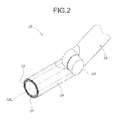
FIG. 2 is an explanatory diagram of links of a robot included in the robot system. -
FIG. 3 is a cross-sectional view of the link of the robot included in the robot system. -
FIG. 4 is a block diagram of robot control device included in the robot system. -
FIG. 5 is a block diagram of an assist torque calculation unit provided in the robot control device included in the robot system. -
FIG. 6 is a block diagram illustrating a modification of the assist torque calculation unit provided in the robot control device included in the robot system. -
FIG. 7 is a block diagram of a flexible control unit provided in the robot control device included in the robot system. -
FIG. 8 is a block diagram of a robot control device included in a robot system according to a second embodiment. -
FIG. 9 is a block diagram of a second retracting direction vector calculation unit provided in the robot control device included in the robot system. -
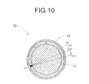
FIG. 10 is an explanatory diagram illustrating a corrected retracting direction vector calculated by the robot control device included in the robot system. - Subsequently, with reference to the accompanying drawings, embodiments embodying the present invention will be described to facilitate understanding of the present invention. The drawings may omit illustrations of portions not involved in the description.
- As illustrated in
FIG. 1 , arobot system 10 according to a first embodiment includes arobot 12 and arobot control device 14 that controls the operation of therobot 12. - The
robot 12 includes, for example, a movingunit 22 for moving on a floor surface, abody 24 that is provided on top of the movingunit 22 with a joint axis AXW therebetween and rotates in fore and aft directions about the joint axis AXW serving as the center of rotation, andarms 26 provided on both sides of thebody 24. Therobot control device 14 may be embedded in therobot 12. - As illustrated in
FIG. 2 , each of thearms 26 includes a plurality oflinks 28 connected with a plurality of joint axes AX therebetween. Each of the joint axes AX is driven by a servo motor SVM (refer toFIG. 4 ) including an encoder ENC. - As illustrated in
FIGS. 2 and3 , each of thelinks 28 of thearms 26 of therobot 12 is provided with, for example, a total of eightrectangular contact sensors 30. Thecontact sensors 30 are provided inside anouter skin 32 covering thelink 28. Theouter skin 32 moderates the impact force applied when thelink 28 touches an object, and thus can protect thecontact sensors 30. - Each of the
contact sensors 30 can output on/off signals according to the state of contact with the object. For example, thecontact sensor 30 can output the on signal when the object is in contact with thelink 28, and can output the off signal when the object is apart from thelink 28. - The
contact sensors 30 are pasted side by side along the outer circumferential direction of thelink 28. Specifically, the outer circumference of thelink 28 is divided into eight regions, and thecontact sensor 30 is pasted in each of the regions. This allows a position on thelink 28 touched by the object to be identified at a resolution of 45 degrees with respect to an angular position about the longitudinal axis AXL of thelink 28 illustrated inFIG. 2 . - The total number of the
contact sensors 30 is not limited to eight. Thecontact sensors 30 need not be provided side by side along the outer circumferential direction of thelink 28. - It is only necessary to divide an area for detection of contact with the object into a plurality of regions in the circumferential or longitudinal direction of the
link 28, and paste thecontact sensor 30 in each of the regions. As a first example, the area for detection of contact with the object may be divided into 16 regions in the circumferential direction of thelink 28, and thecontact sensor 30 may be provided in each of the regions. As a second example, the area for detection of contact with the object may be divided into eight in the circumferential direction and two in the longitudinal direction of thelink 28, thus being divided into a total of 16 regions, and thecontact sensor 30 may be provided in each of the regions. - The
contact sensor 30 is not limited to the contact sensor that outputs the on/off signals. Other examples of the contact sensor include a sensor that adjusts the level of an output signal thereof according to the magnitude of the contact force (contact pressure) applied thereto. - These
contact sensors 30 constitute an example of a contact detection sensor that can detect the contact of thelink 28 with the object. The contact detection sensor only needs to be capable of detecting the position or an area including the position on thelink 28 touched by the object. - As illustrated in
FIG. 4 , therobot control device 14 includes areference generating unit 42, a sensorsignal input unit 44, a contactposition determination unit 46, a first retracting directionvector calculation unit 48, an assisttorque calculation unit 50, and aflexible control unit 52 that outputs torque references τref to servo amplifiers SVA connected to the respective servo motors SVM. Therobot control device 14 has an embedded CPU and memory (not illustrated). The blocks illustrated inFIG. 4 are implemented by a software program executed by the CPU and hardware. -
FIG. 4 collectively represents thecontact sensors 30, the servo motors SVM, the encoders ENC, and the servo amplifiers SVA as respective single blocks. - The
reference generating unit 42 can generate position references Pref to the servo motors SVM for rotationally moving thelinks 28 of therobot 12 to move a tip of thearms 26. The generated position references Pref are entered into theflexible control unit 52. - The
contact sensors 30 are connected to the sensorsignal input unit 44. The sensorsignal input unit 44 functions as an interface for thecontact sensors 30. The sensorsignal input unit 44 outputs signals corresponding to the on/off signals of thecontact sensors 30. These signals are entered into thereference generating unit 42. - Based on the output signals of the sensor
signal input unit 44, the contactposition determination unit 46 can determine the position on thelink 28 touched by the object as a contact position Pc. - The on/off signals output by the
contact sensors 30 are entered into the contactposition determination unit 46 via the sensorsignal input unit 44. The contactposition determination unit 46 detects the on signal output by any one of the eightcontact sensors 30, and thus identifies thecontact sensor 30 touched by the object. - After identifying the
contact sensor 30 touched by the object, the contactposition determination unit 46 can obtain a predetermined point corresponding to thecontact sensor 30 as the contact position Pc illustrated inFIG. 3 . - The contact position Pc is predetermined, for example, as a center position of a surface of each of the
contact sensors 30. The contact position Pc is not limited to the center position of the surface of thecontact sensor 30, but may be any position that corresponds to thecontact sensor 30. - Because the contact position Pc is predetermined, the position on the
link 28 actually touched by the object may differ from the contact position Pc obtained by the contactposition determination unit 46, as illustrated inFIG. 3 . However, increasing the number of the divided regions on which the contact sensors are pasted brings the position on thelink 28 actually touched by the object into closer agreement with the contact position Pc. Alternatively, providing a sensor also outputting a contact position instead of thecontact sensor 30 brings the position on thelink 28 actually touched by the object into substantial agreement with the contact position Pc. - By using a coordinate transformation matrix T derived from angle information of the respective joint axes AX obtained from signals of the encoders ENC of the servo motors SVM driving the
links 28 of therobot 12, the contact position Pc is calculated, for example, as a position in a robot coordinate system fixed to thebody 24 of therobot 12. - The contact
position determination unit 46 may be configured to detect a plurality of contact positions.
That case allows the contactposition determination unit 46 to output a plurality of calculated contact positions. - According to the contact position Pc, the first retracting direction
vector calculation unit 48 illustrated inFIG. 4 can calculate the direction of movement (retracting direction) of thelink 28 as a retracting direction vector n. - The retracting direction vector n is predetermined, and is, for example, a unit vector in the normal direction of a surface of the
link 28 in the contact position Pc. Therefore, the direction of the retracting direction vector n may differ from the direction of the external force fc received from the object in contact with thelink 28 as illustrated inFIG. 3 . - The retracting direction vector n is calculated as a vector in the robot coordinate system by using the above-described coordinate transformation matrix T.
- Based on the contact position Pc and the retracting direction vector n, the assist
torque calculation unit 50 illustrated inFIG. 4 can calculate an assist torque reference τa for each of the joint axes AX of therobot 12. - As illustrated in
FIG. 5 , the assisttorque calculation unit 50 includes an assistforce determination unit 50a, an assist forcevector calculation unit 50b, and atorque calculation unit 50c. - The assist
force determination unit 50a can determine the magnitude of the assist force f for retracting the links 28 (arm 26), and can output the assist force f as a scalar quantity. Changing the assist force f depending on the situation can adjust flexibility of the joint axes AX of thearm 26 included in therobot 12. - For example, the assist
force determination unit 50a can output the assist force f having a larger first magnitude after thelink 28 touches the object until a predetermined time tim (such as 1 to 10 milliseconds) passes, and can output the assist force f having a second magnitude smaller than the first magnitude after the time tim has passed. In this manner, after thelink 28 touches the object, the assistforce determination unit 50a first outputs the assist force f having the larger first magnitude so as to quickly move thelink 28 in the retracting direction, thus suppressing the contact force (impact force). - When the contact sensor is the above-mentioned sensor that adjusts the level of the output signal thereof according to the magnitude of the contact force (contact pressure), the assist
force determination unit 50a may determine the assist force f based on the level of this signal. - Based on the assist force f and the retracting direction vector n calculated by the first retracting direction
vector calculation unit 48, the assist forcevector calculation unit 50b can calculate an assist force vector Fa in the contact position Pc using the following equation.
- The
torque calculation unit 50c can obtain a Jacobian transpose JT in the calculated contact position from the calculated contact position calculated by the contactposition determination unit 46, and can calculate the assist torque reference τa for the servo motor SVM driving each of the joint axes AX using the following equation. The assist torque reference τa is a torque reference for each of the joint axes AX for moving thelink 28 in the direction of the retracting direction vector.
- The assist torque calculation unit may be an assist
torque calculation unit 50x that further includes aweight calculation unit 50d between the assist forcevector calculation unit 50b and thetorque calculation unit 50c, as illustrated inFIG. 6 . - As represented in the following equation, the
weight calculation unit 50d can multiply the assist force vector Fa output from the assist forcevector calculation unit 50b of the preceding block by a weighting factor matrix k, and can output the result to thetorque calculation unit 50c of the subsequent block. The weighting factor matrix k is a diagonal matrix for adjusting the magnitude of assist torque (torque for moving thelink 28 in the direction of the retracting direction vector) to be generated by each of the joint axes AX of thelink 28. - The weighting factor matrix k is set, for example, as follows.
- As a first example, the weighting factor matrix k is set according to amounts of coefficients of viscous friction of reduction gears, etc. provided at the joint axes AX. Specifically, the weighting factor matrix k is set so as to increase the assist torque reference for the servo motor SVM driving each of the joint axes AX according to the amount of the coefficient of viscous friction of the joint axis AX. In other words, the weighting factor matrix k performs weighting so as to give the joint axis AX having a larger coefficient of viscous friction a larger magnitude of assist torque.
- Setting the weighting factor matrix k as exemplified in the first example absorbs differences in the viscous friction of the joint axes AX, thus allowing the links 28 (arm 26) to perform a natural operation.
- As a second example, the weighting factor matrix k performs weighting so as to give the largest magnitude of assist torque to the joint axis AX located at the root (base end) of the
link 28 that touches the object. More specifically, the weighting factor matrix k performs weighting so as to give a larger magnitude of assist torque to the joint axis AX nearer to the contact position Pc on thelink 28 that touches the object, among all of the joint axes AX located on the side nearer to the root (base end) of thearm 26 than the contact position Pc. - Setting the weighting factor matrix k as exemplified in the second example improves performance to absorb the external force received from the touched object because the axis nearer to the contact position Pc performs a retracting operation more quickly.
- The
torque calculation unit 50c of the assisttorque calculation unit 50x calculates the assist torque references τa given by the following equation.
- Based on the position references Pref and the assist torque references τa, the
flexible control unit 52 illustrated inFIG. 4 can output the torque references τref for driving the servo motors SVM to the servo amplifiers SVA, and thus can perform control so as to flexibly operate the joint axes AX of therobot 12. - As illustrated in
FIG. 7 , theflexible control unit 52 includes a position/speed control unit 52a, a torque limitvalue calculation unit 52b, atorque limiting unit 52c, and a gravity compensationtorque calculation unit 52d. - Position/speed control loops (servo loops) are formed in the position/
speed control unit 52a. The position/speed control unit 52a can output a torque reference τb according to a position error e between an angle feedback (encoder value) Pfb of each of the servo motors SVM obtained from the encoders ENC and the position reference Pref generated by thereference generating unit 42. - The torque limit
value calculation unit 52b can obtain a torque limit value Tlim. - The torque limit
value calculation unit 52b can obtain the torque limit value (upper or lower limit value) Tlim, for example, so as to include therebetween torque of the servo motor SVM required for motion of the links 28 (torque for accelerating both thelinks 28 and a tip load of thearm 26, and torque for maintaining movement velocities of the links 28). - As another example, the torque limit
value calculation unit 52b can obtain a predetermined maximum torque value of the servo motor SVM as the torque limit value Tlim. - The
torque limiting unit 52c can limit the torque reference τb output by the position/speed control unit 52a with the torque limit value Tlim calculated by the torque limitvalue calculation unit 52b, and thus can output a limited torque reference τlim. - The gravity compensation
torque calculation unit 52d can calculate torque by gravity of each of the joint axes AX as gravity compensation torque τg by calculation of dynamics based on the encoder value Pfb of each of the servo motors SVM. - The calculated gravity compensation torque τg is added together with the assist torque reference τa to the torque reference τlim output by the
torque limiting unit 52c. - This keeps the
links 28 from dropping and the torque required for moving thelinks 28 from being insufficient due to the limitation of the torque reference by thetorque limiting unit 52c. - A description will be made below of the operation of the
robot system 10 separately for a case in which thearm 26 is not in contact with the object, and for another case in which thearm 26 is in contact with the object. - The position/
speed control unit 52a of theflexible control unit 52 outputs the torque reference τb based on the position reference Pref generated by thereference generating unit 42. If the torque reference τb exceeds the torque limit value Tlim, thetorque limiting unit 52c limits the magnitude of the torque reference and outputs it as the torque reference τlim (refer toFIG. 7 ). - The assist
torque calculation unit 50 does not output the assist torque reference τa because each of thecontact sensors 30 does not output the on signal. In other words, the magnitude of the assist torque reference τa is zero. - The gravity compensation
torque calculation unit 52d outputs the gravity compensation torque τg based on the encoder value Pfb. - Accordingly, the gravity compensation torque τg calculated by the gravity compensation
torque calculation unit 52d is added to the torque reference τlim, and the torque reference τref is output to the servo amplifier SVA (refer toFIG. 4 ). - As a result, each of the servo motors SVM is driven according to the torque reference τref, and the
arm 26 of therobot 12 operates. - The addition of the gravity compensation torque τg to the torque reference τref keeps the
arm 26 from dropping by its own weight. - The operation of the
robot system 10 differs depending on whether thearm 26 is retracted from the touched object or moves following the external force fc received from the touched object. The operation will be described below for separate cases. - Based on the signal output by the sensor
signal input unit 44, thereference generating unit 42 stops outputting the position reference Pref. - The position/
speed control unit 52a of theflexible control unit 52 outputs the torque reference τb according to the position error e. - The torque limit
value calculation unit 52b determines that the output of the position reference Pref has been stopped, and sets the torque limit value Tlim to zero. It follows that thetorque limiting unit 52c sets the torque reference τlim to zero regardless of the torque reference τb. - The assist
torque calculation unit 50 outputs the assist torque reference τa according to the contact position Pc. - The gravity compensation
torque calculation unit 52d outputs the gravity compensation torque τg based on the encoder value Pfb. - Accordingly, while the torque reference τlim output by the
torque limiting unit 52c is set to zero, the assist torque reference τa and the gravity compensation torque τg are added to the torque reference τlim at the block subsequent to thetorque limiting unit 52c, and the result is output as the torque reference τref. - As a result, each of the servo motors SVM is driven according to the torque reference τref, and the
links 28 are retracted by the assist torque from the touched object. - The addition of the gravity compensation torque τg to the torque reference τref keeps the
arm 26 from dropping by its own weight. - The
reference generating unit 42 continues outputting the position reference Pref. - The position/
speed control unit 52a of theflexible control unit 52 outputs the torque reference τb based on the position reference Pref generated by thereference generating unit 42. If the torque reference τb output by the position/speed control unit 52a exceeds the torque limit value Tlim, thetorque limiting unit 52c limits the magnitude of the torque reference and outputs it as the torque reference τlim. - The assist
torque calculation unit 50 outputs the assist torque reference τa according to the contact position Pc. - The gravity compensation
torque calculation unit 52d outputs the gravity compensation torque τg based on the encoder value Pfb. - Accordingly, the assist torque reference τa and the gravity compensation torque τg are added to the torque reference τlim output by the
torque limiting unit 52c, and the torque reference τref is output. - This results in driving of each of the servo motors SVM according to the torque reference τref. The limitation of the magnitude of the torque reference τb by the
torque limiting unit 52c allows the links 28 (arm 26) to follow the external force fc received from the touched object. At the same time, the continuation of the output of the position reference Pref causes the joint axes AX of thearm 26 to try to continue the movement toward a target position as much as possible while following the external force fc. - The addition of the assist torque reference τa to the torque reference τref causes the joint axes AX of the
arm 26 to flexibly operate in the direction of following the external force fc. - The further addition of the gravity compensation torque τg to the torque reference τref keeps the
links 28 from dropping by their own weight. - As described above, the addition of the assist torque allows the
robot system 10 according to the present embodiment to flexibly operate the joint axes AX of thearm 26. In addition, an impact applied to the object touching thelink 28 can be suppressed. - Subsequently, a description will be made of a robot system according to a second embodiment. The same components as those of the
robot system 10 according to the first embodiment may be given the same symbols, and detailed description thereof may be omitted. - As illustrated in
FIG. 8 , a robot control device 114 of the robot system according to the present embodiment includes a second retracting directionvector calculation unit 148, instead of the first retracting directionvector calculation unit 48. - As illustrated in
FIG. 9 , the second retracting directionvector calculation unit 148 includes a contact portion normalvector calculation unit 148a that can calculate the retracting direction vector n (refer toFIG. 10 ), a contact point movementvector calculation unit 148b that can calculate a movement vector m, and a retracting directionvector correction unit 148c that can correct the retracting direction vector n based on the movement vector m. - According to the contact position Pc, the contact portion normal
vector calculation unit 148a can calculate the direction of movement of thelink 28 as the retracting direction vector n. The retracting direction vector n is predetermined, and is, for example, a unit vector in the normal direction of the surface of thelink 28 in the contact position. - From the angles of the joint axes AX calculated based on the encoder values Pfb of the servo motors SVM and the contact position Pc obtained by the contact
position determination unit 46, the contact point movementvector calculation unit 148b can calculate a vector representing the direction of actual movement of the contact position Pc as the movement vector m. - The retracting direction
vector correction unit 148c can calculate a difference vector vd between the retracting direction vector n calculated by the contact portion normalvector calculation unit 148a and the movement vector m calculated by the contact point movementvector calculation unit 148b. - The retracting direction
vector correction unit 148c can further calculate a vector by combining the difference vector vd with the retracting direction vector n as a new retracting direction vector nc. - In other words, based on the encoder values Pfb of the servo motors SVM, the second retracting direction
vector calculation unit 148 can correct the retracting direction vector n calculated by the contact portion normalvector calculation unit 148a to calculate the corrected retracting direction vector nc so as to be able to move thelink 28 in the direction of the predetermined retracting direction vector n, as illustrated inFIG. 10 . - The robot system according to the present embodiment can move the
link 28 in the predetermined retracting direction more accurately than in the case of not having the configuration of the present embodiment. - The present invention is not limited to the above-described embodiments, and can be modified within the scope of not changing the gist of the present invention. For example, the technical scope of the present invention includes a case of constituting the invention by combining some or all of the embodiments and the modification described above.
- The robot is not limited to a robot that includes the moving unit, the body provided on top of the moving unit, and the arms provided on both sides of the body. The robot may be an industrial robot that includes, for example, links connected by joint axes.
- The present invention is applied not only to the
arms 26 exemplified in the above-described embodiments. The present invention can also be applied with respect to, for example, the joint axis AXW between thebody 24 and the movingunit 22. -
- 10
- Robot system
- 12
- Robot
- 14
- Robot control device
- 22
- Moving unit
- 24
- Body
- 26
- Arm
- 28
- Link
- 30
- Contact sensor
- 32
- Outer skin
- 42
- Reference generating unit
- 44
- Sensor signal input unit
- 46
- Contact position determination unit
- 48
- First retracting direction vector calculation unit
- 50
- Assist torque calculation unit
- 50a
- Assist force determination unit
- 50b
- Assist force vector calculation unit
- 50c
- Torque calculation unit
- 50d
- Weight calculation unit
- 50x
- Assist torque calculation unit
- 52
- Flexible control unit
- 52a
- Position/speed control unit
- 52b
- Torque limit value calculation unit
- 52c
- Torque limiting unit
- 52d
- Gravity compensation torque calculation unit
- 114
- Robot control device
- 148
- Second retracting direction vector calculation unit
- 148a
- Contact portion normal vector calculation unit
- 148b
- Contact point movement vector calculation unit
- 148c
- Retracting direction vector correction unit
- ENC
- Encoder
- SVA
- Servo amplifier
- SVM
- Servo motor
- AX
- Joint axis
Claims (11)
- A robot system comprising:a robot that comprises:a plurality of links connected via a plurality of joint axes;servo motors that drive the joint axes; anda contact detection sensor that detects that one of the links touches an object; anda robot control device that controls the robot,the robot control device comprising:a contact position determination unit that determines a contact position on the link with the object on the basis of an output from the contact detection sensor;a retracting direction vector calculation unit that calculates a retracting direction vector in a retracting direction of the link corresponding to the contact position determined by the contact position determination unit;an assist torque calculation unit that calculates assist torque references that are torque references for the servo motors for moving the links in the direction of the retracting direction vector; anda flexible control unit that adds the assist torque references to torque references for the servo motors to flexibly control the links.
- The robot system according to claim 1, wherein
the assist torque calculation unit comprises:an assist force determination unit that determines a magnitude of assist force for retracting the links;an assist force vector calculation unit that calculates an assist force vector on the basis of the retracting direction vector of the links and the magnitude of the assist force; anda torque calculation unit that calculates the assist torque references on the basis of the assist force vector. - The robot system according to claim 1, wherein
the assist torque calculation unit comprises:an assist force determination unit that determines a magnitude of assist force for retracting the links;an assist force vector calculation unit that calculates an assist force vector on the basis of the retracting direction vector of the links and the magnitude of the assist force;a weight calculation unit that multiplies the assist force vector by a weighting factor matrix for adjusting magnitudes of the assist torque references for the servo motors to calculate the assist force vector to which weight adjustment is applied; anda torque calculation unit that calculates the assist torque references on the basis of the assist force vector calculated by the weight calculation unit. - The robot system according to claim 3, wherein the weighting factor matrix is a matrix that performs weighting so as to give a larger magnitude of assist torque for moving the links in the direction of the retracting direction vector to the joint axis having a larger coefficient of viscous friction.
- The robot system according to claim 3, wherein the weighting factor matrix is a matrix that performs weighting so as to give a largest magnitude of assist torque for moving the links in the direction of the retracting direction vector to the joint axis located at a base end of the link, among the joint axes located close to the base end of the link that touches the object.
- The robot system according to claim 5, wherein the weighting factor matrix is a matrix that performs weighting so as to give a larger magnitude of the assist torque to the joint axis nearer to the link that touches the object, among the joint axes located close to the base end of the link that touches the object.
- The robot system according to any one of claims 2 to 6, wherein the assist force determination unit determines the magnitude of the assist torque to be a first magnitude until a predetermined time tim passes after the link touches the object, and determines the magnitude of the assist torque to be a second magnitude smaller than the first magnitude after the time tim has passed.
- A robot system comprising:a robot that comprises:a plurality of links connected via a plurality of joint axes;servo motors that drive the joint axes; anda contact detection sensor that detects that one of the links touches an object; anda robot control device that controls the robot,the robot control device comprising:a contact position determination unit that determines a contact position on the link with the object on the basis of an output from the contact detection sensor;a retracting direction vector calculation unit comprising:1) a contact portion normal vector calculation unit that calculates a retracting direction vector in a retracting direction of the link corresponding to the contact position determined by the contact position determination unit;2) a contact point movement vector calculation unit that calculates a movement vector representing a direction of actual movement of the contact position determined by the contact position determination unit; and3) a retracting direction vector correction unit that corrects the retracting direction vector on the basis of the movement vector;an assist torque calculation unit that calculates assist torque references that are torque references for the servo motors for moving the links in the direction of the retracting direction vector corrected by the retracting direction vector calculation unit; anda flexible control unit that adds the assist torque references to torque references for the servo motors to flexibly control the links.
- A robot comprising:a plurality of links connected via a plurality of joint axes; andservo motors that drive the joint axes,each of the links comprising a plurality of contact detection sensors that are provided side by side along an outer circumferential direction of the corresponding link to detect that the corresponding link touches an object.
- A robot control device comprising:a contact position determination unit that determines, when one of links of a robot driven by a plurality of servo motors touches an object, a contact position on the link;a retracting direction vector calculation unit that calculates a retracting direction vector in a retracting direction of the link corresponding to the contact position;an assist torque calculation unit that calculates assist torque references that are torque references for the servo motors for moving the links in the direction of the retracting direction vector; anda flexible control unit that adds the assist torque references to torque references for the servo motors to flexibly control the links.
- A robot control device comprising:a contact position determination unit that determines, when one of links of a robot driven by a plurality of servo motors touches an object, a contact position on the link;a retracting direction vector calculation unit comprising:1) a contact portion normal vector calculation unit that calculates a retracting direction vector in a retracting direction of the link corresponding to the contact position determined by the contact position determination unit;2) a contact point movement vector calculation unit that calculates a movement vector representing a direction of actual movement of the contact position determined by the contact position determination unit; and3) a retracting direction vector correction unit that corrects the retracting direction vector on the basis of the movement vector;an assist torque calculation unit that calculates assist torque references that are torque references for the servo motors for moving the links in the direction of the retracting direction vector corrected by the retracting direction vector calculation unit; anda flexible control unit that adds the assist torque references to torque references for the servo motors to flexibly control the links.
Applications Claiming Priority (1)
| Application Number | Priority Date | Filing Date | Title |
|---|---|---|---|
| PCT/JP2011/068794 WO2013027250A1 (en) | 2011-08-19 | 2011-08-19 | Robot system, robot, and robot control device |
Publications (2)
| Publication Number | Publication Date |
|---|---|
| EP2746000A1 true EP2746000A1 (en) | 2014-06-25 |
| EP2746000A4 EP2746000A4 (en) | 2015-08-19 |
Family
ID=47746032
Family Applications (1)
| Application Number | Title | Priority Date | Filing Date |
|---|---|---|---|
| EP11871270.2A Withdrawn EP2746000A4 (en) | 2011-08-19 | 2011-08-19 | ROBOTIC SYSTEM, ROBOT AND ROBOT CONTROL DEVICE |
Country Status (4)
| Country | Link |
|---|---|
| US (1) | US20140163735A1 (en) |
| EP (1) | EP2746000A4 (en) |
| CN (1) | CN103747927A (en) |
| WO (1) | WO2013027250A1 (en) |
Families Citing this family (16)
| Publication number | Priority date | Publication date | Assignee | Title |
|---|---|---|---|---|
| JP5929854B2 (en) * | 2013-07-31 | 2016-06-08 | 株式会社安川電機 | Robot system and method of manufacturing workpiece |
| US9452532B2 (en) * | 2014-01-27 | 2016-09-27 | Panasonic Intellectual Property Management Co., Ltd. | Robot, device and method for controlling robot, and computer-readable non-transitory recording medium |
| JP6193816B2 (en) * | 2014-06-20 | 2017-09-06 | ファナック株式会社 | Articulated robot with arm retracting function |
| JP6443837B2 (en) * | 2014-09-29 | 2018-12-26 | セイコーエプソン株式会社 | Robot, robot system, control device, and control method |
| JP6677441B2 (en) * | 2014-10-20 | 2020-04-08 | 株式会社デンソーウェーブ | Robot, robot shape design method |
| JP6706489B2 (en) * | 2015-11-24 | 2020-06-10 | 川崎重工業株式会社 | Robot direct teaching method |
| US11192251B2 (en) | 2015-11-26 | 2021-12-07 | Institut De Recherche Technologique Jules Verne | Method and device for controlling a robot during co-activity |
| CN105700438A (en) * | 2016-03-18 | 2016-06-22 | 北京光年无限科技有限公司 | Electronic control system for multi-joint small robot |
| JP6670147B2 (en) * | 2016-03-28 | 2020-03-18 | 日立Geニュークリア・エナジー株式会社 | MANIPULATOR AND MANIPULATOR CONTROL METHOD |
| JP6960242B2 (en) * | 2017-05-19 | 2021-11-05 | 川崎重工業株式会社 | Robot system and robot system control method |
| CN108161939B (en) * | 2017-12-29 | 2020-11-03 | 深圳市越疆科技有限公司 | Flexible obstacle avoidance method and system for mechanical arm and terminal equipment |
| JP7127316B2 (en) * | 2018-03-22 | 2022-08-30 | カシオ計算機株式会社 | Robot, robot control method and program |
| JP7375754B2 (en) * | 2018-07-17 | 2023-11-08 | ソニーグループ株式会社 | Control device, control method, and control system |
| WO2020030284A1 (en) * | 2018-08-10 | 2020-02-13 | Abb Schweiz Ag | Method for controlling movement of a robot |
| DE102019128082B4 (en) * | 2019-10-17 | 2022-03-10 | Franka Emika Gmbh | Torque-limited braking of a robotic manipulator |
| CN116322553B (en) * | 2020-10-07 | 2026-03-17 | 奥瑞斯健康公司 | Systems and methods for activating manual operation using linkage interaction sensing. |
Family Cites Families (17)
| Publication number | Priority date | Publication date | Assignee | Title |
|---|---|---|---|---|
| JPS6029496U (en) * | 1983-08-05 | 1985-02-27 | 株式会社神戸製鋼所 | Contact detection device for robots, etc. |
| JPS6029494U (en) * | 1983-08-05 | 1985-02-27 | 株式会社神戸製鋼所 | Contact detection device for robots, etc. |
| JPH08393B2 (en) * | 1993-03-26 | 1996-01-10 | 日本電気株式会社 | Robot arm with collision prevention function |
| JP3300625B2 (en) | 1997-01-27 | 2002-07-08 | ファナック株式会社 | Robot control method |
| JP3865158B2 (en) * | 1997-05-30 | 2007-01-10 | 株式会社安川電機 | Impedance control device for robot arm |
| JP2001038664A (en) * | 1999-08-04 | 2001-02-13 | Yaskawa Electric Corp | Impedance control device for robot arm |
| JP3383614B2 (en) * | 1999-08-04 | 2003-03-04 | 技術研究組合医療福祉機器研究所 | Impedance control device for horizontal articulated robot arm |
| JP3951007B2 (en) * | 2001-09-14 | 2007-08-01 | 独立行政法人産業技術総合研究所 | Robot control device with tactile sensor |
| JP4134812B2 (en) * | 2003-05-20 | 2008-08-20 | 株式会社安川電機 | Robot controller |
| EP1652634B1 (en) * | 2003-07-29 | 2011-12-28 | Panasonic Corporation | Robot arm control method and control device |
| JP2005059161A (en) * | 2003-08-18 | 2005-03-10 | Univ Waseda | Robot controller |
| JP2005100143A (en) * | 2003-09-25 | 2005-04-14 | Kobe Steel Ltd | Control method and control device for motor-driven device |
| DE102005015317B4 (en) * | 2005-04-01 | 2007-02-01 | Siemens Ag | Method and control device for targeted reaction in contact between a machine element of a machine with an object |
| US20100168919A1 (en) * | 2006-03-24 | 2010-07-01 | Matsushita Electric Industrial Co, Ltd. | Control method and control system for manipulator |
| JP4271249B2 (en) * | 2007-06-14 | 2009-06-03 | ファナック株式会社 | Mating device |
| JP5261495B2 (en) * | 2007-11-01 | 2013-08-14 | 本田技研工業株式会社 | Real-time self-collision and obstacle avoidance using weight matrix |
| US20090306825A1 (en) * | 2008-04-21 | 2009-12-10 | Ying Li | Manipulation system and method |
-
2011
- 2011-08-19 WO PCT/JP2011/068794 patent/WO2013027250A1/en not_active Ceased
- 2011-08-19 EP EP11871270.2A patent/EP2746000A4/en not_active Withdrawn
- 2011-08-19 CN CN201180072954.8A patent/CN103747927A/en active Pending
-
2014
- 2014-02-17 US US14/181,729 patent/US20140163735A1/en not_active Abandoned
Also Published As
| Publication number | Publication date |
|---|---|
| US20140163735A1 (en) | 2014-06-12 |
| WO2013027250A1 (en) | 2013-02-28 |
| EP2746000A4 (en) | 2015-08-19 |
| CN103747927A (en) | 2014-04-23 |
Similar Documents
| Publication | Publication Date | Title |
|---|---|---|
| US20140163735A1 (en) | Robot system, robot, and robot control device | |
| US9616564B2 (en) | Event-based redundancy angle configuration for articulated-arm robots | |
| US10751874B2 (en) | Method of teaching robot and robotic arm control device | |
| JP6238021B2 (en) | ROBOT, ROBOT CONTROL DEVICE AND CONTROL METHOD, AND ROBOT CONTROL PROGRAM | |
| US10864632B2 (en) | Direct teaching method of robot | |
| JP6314426B2 (en) | Robot control apparatus and robot control method | |
| US9517562B2 (en) | Robot controller, robot system, robot control method | |
| US9044861B2 (en) | Robot | |
| JP5929224B2 (en) | robot | |
| CN110621446B (en) | Robot system and control method for robot system | |
| US9555548B2 (en) | Robot control device for controlling robot moved according to applied force | |
| US20130006422A1 (en) | Control apparatus and control method for robot, robot, and control program therefor | |
| JP5916583B2 (en) | Weaving control device for articulated robot | |
| US10838408B2 (en) | Vibration control device, vibration control method, vibration control system, program, and recording medium | |
| WO2016073367A1 (en) | Position/force control of a flexible manipulator under model-less control | |
| JP2015116663A (en) | Control method of robot device, and robot device | |
| JP2015202534A (en) | Robot control device and robot system for robot moved according to input power | |
| US20110087374A1 (en) | Robot system | |
| US9827673B2 (en) | Robot controller inhibiting shaking of tool tip in robot equipped with travel axis | |
| JP2016190292A (en) | Robot control apparatus, robot system, and robot control method | |
| US20150051735A1 (en) | Control apparatus of robot, robot, and program thereof | |
| JP5774552B2 (en) | Robot controller | |
| JP2012051043A (en) | Robot system or robot control device | |
| JP6400538B2 (en) | Robot control device for controlling a robot driven by a motor | |
| JP2009113147A (en) | Robot and robot control method |
Legal Events
| Date | Code | Title | Description |
|---|---|---|---|
| PUAI | Public reference made under article 153(3) epc to a published international application that has entered the european phase |
Free format text: ORIGINAL CODE: 0009012 |
|
| 17P | Request for examination filed |
Effective date: 20140217 |
|
| AK | Designated contracting states |
Kind code of ref document: A1 Designated state(s): AL AT BE BG CH CY CZ DE DK EE ES FI FR GB GR HR HU IE IS IT LI LT LU LV MC MK MT NL NO PL PT RO RS SE SI SK SM TR |
|
| DAX | Request for extension of the european patent (deleted) | ||
| RIC1 | Information provided on ipc code assigned before grant |
Ipc: B25J 13/08 20060101AFI20150318BHEP Ipc: B25J 9/16 20060101ALI20150318BHEP Ipc: B25J 13/00 20060101ALI20150318BHEP |
|
| STAA | Information on the status of an ep patent application or granted ep patent |
Free format text: STATUS: THE APPLICATION HAS BEEN WITHDRAWN |
|
| RA4 | Supplementary search report drawn up and despatched (corrected) |
Effective date: 20150722 |
|
| RIC1 | Information provided on ipc code assigned before grant |
Ipc: B25J 13/08 20060101AFI20150716BHEP Ipc: B25J 13/00 20060101ALI20150716BHEP Ipc: B25J 9/16 20060101ALI20150716BHEP |
|
| 18W | Application withdrawn |
Effective date: 20150807 |