EP2745962A2 - Method for machining metallic member using lathing and scraping - Google Patents
Method for machining metallic member using lathing and scraping Download PDFInfo
- Publication number
- EP2745962A2 EP2745962A2 EP20130197294 EP13197294A EP2745962A2 EP 2745962 A2 EP2745962 A2 EP 2745962A2 EP 20130197294 EP20130197294 EP 20130197294 EP 13197294 A EP13197294 A EP 13197294A EP 2745962 A2 EP2745962 A2 EP 2745962A2
- Authority
- EP
- European Patent Office
- Prior art keywords
- scraping
- metallic member
- along
- scraping cutter
- feeding mechanism
- Prior art date
- Legal status (The legal status is an assumption and is not a legal conclusion. Google has not performed a legal analysis and makes no representation as to the accuracy of the status listed.)
- Granted
Links
Images




Classifications
-
- B—PERFORMING OPERATIONS; TRANSPORTING
- B23—MACHINE TOOLS; METAL-WORKING NOT OTHERWISE PROVIDED FOR
- B23B—TURNING; BORING
- B23B3/00—General-purpose turning-machines or devices, e.g. centre lathes with feed rod and lead screw; Sets of turning-machines
- B23B3/06—Turning-machines or devices characterised only by the special arrangement of constructional units
- B23B3/065—Arrangements for performing other machining operations, e.g. milling, drilling
-
- B—PERFORMING OPERATIONS; TRANSPORTING
- B23—MACHINE TOOLS; METAL-WORKING NOT OTHERWISE PROVIDED FOR
- B23B—TURNING; BORING
- B23B5/00—Turning-machines or devices specially adapted for particular work; Accessories specially adapted therefor
- B23B5/36—Turning-machines or devices specially adapted for particular work; Accessories specially adapted therefor for turning specially-shaped surfaces by making use of relative movement of the tool and work produced by geometrical mechanisms, i.e. forming-lathes
-
- B—PERFORMING OPERATIONS; TRANSPORTING
- B23—MACHINE TOOLS; METAL-WORKING NOT OTHERWISE PROVIDED FOR
- B23D—PLANING; SLOTTING; SHEARING; BROACHING; SAWING; FILING; SCRAPING; LIKE OPERATIONS FOR WORKING METAL BY REMOVING MATERIAL, NOT OTHERWISE PROVIDED FOR
- B23D5/00—Planing or slotting machines cutting otherwise than by relative movement of the tool and workpiece in a straight line
-
- B—PERFORMING OPERATIONS; TRANSPORTING
- B23—MACHINE TOOLS; METAL-WORKING NOT OTHERWISE PROVIDED FOR
- B23P—METAL-WORKING NOT OTHERWISE PROVIDED FOR; COMBINED OPERATIONS; UNIVERSAL MACHINE TOOLS
- B23P23/00—Machines or arrangements of machines for performing specified combinations of different metal-working operations not covered by a single other subclass
- B23P23/02—Machine tools for performing different machining operations
Definitions
- the present disclosure generally relates to methods for machining a metallic member, and particularly, to a method for machining member using lathing and scraping.
- An electronic device such as a tabletop computer or a mobile phone may have a housing made of metal.
- the metallic housing includes a top portion and a peripheral sidewall extending from a peripheral edge of the top portion.
- the top portion has a greater surface area than that of the peripheral sidewall and has a non-circular flat surface or non-circular curved surface.
- the peripheral sidewall has four side surfaces arranged in order and adjacent two side surfaces connected by corners.
- a machining method for machining metallic member using lathing and scraping includes: (1) providing a machine comprising a machine support, a worktable, a moving device, a lathe feeding mechanism, and a scraping feeding mechanism, wherein the worktable is positioned on the machine support; the moving device is slidably assembled to the machine support along a first direction and located above the worktable, the lathe feeding mechanism and the scraping feeding mechanism are slidably assembled to the moving device along a second direction perpendicular to the first direction, the lathe feeding mechanism comprises at least one feeding assembly and a lathe tool connected to the at least one feeding assembly, the at least one feeding assembly is configured for driving the lathe tool to move along a third direction substantially perpendicular to the first and second direction reciprocally, the scraping feeding mechanism comprises a scraping cutter and is configured for driving the scraping cutter to move along the third direction; (2) positioning a metallic member on the worktable, the metallic member comprising a top portion and a peripheral sidewall extending from
- FIGS. 1 and 2 show a first embodiment of a machine 100 adopting a scraping method for machining a metallic member 300 (see FIG. 5 ).
- the machine 100 includes a machine support 10, a worktable 20, a moving device 30, a lathe feeding mechanism 40, a scraping feeding mechanism 50, and a controller 60.
- the worktable 20 holds a workpiece in place and is supported by the machine support 10.
- the moving device 30 is movably positioned on the machine support 10 above the worktable 20.
- the lathe feeding mechanism 40 and the scraping feeding mechanism 50 are arranged side by side and slidably mounted on the moving device 30.
- the controller 60 is electrically connected to the worktable 20, the moving device 30, the lathe feeding mechanism 40, and the scraping feeding mechanism 50 for controlling the machine 100.
- the moving device 30 can be driven to move with the lathe feeding mechanism 40 and the scraping feeding mechanism 50, such that the lathe feeding mechanism 40 and the scraping feeding mechanism 50 can be driven three-dimensionally along Cartesian coordinates, that is, along the X, the Y, and the Z axes.
- the machine support 10 includes a base 11 and a pair of support bodies 13 positioned on the base 11.
- the pair of support bodies 13 is parallel to each other and arranged apart from each other.
- Each support body 13 includes a first sliding rail 131 on a surface away from the base 11. In the illustrated embodiment, the first sliding rail 131 extends substantially parallel to the X-axis (a first direction).
- the worktable 20 is rotatably positioned on the base 11 between the two support bodies 13.
- the worktable 20 includes a pair of mounting bases 21, a first rotating member 23, a rotating shaft 25, and a second rotating member 27.
- the pair of mounting bases 21 is located in the middle portion of the base 11, in parallel.
- the pair of mounting bases 21 is located between the two support bodies 13.
- the first rotating member 23 is mounted on one mounting base 21.
- the rotating shaft 25 interconnects the first rotating member 23 and the other one mounting base 21.
- the first rotating member 23 is capable of rotating the rotating shaft 25 around an ⁇ axis.
- the ⁇ axis is parallel to the Y-axis but is not co-linear (a second direction).
- the second rotating member 27 is positioned on a middle portion of the rotating shaft 25, and capable of rotating the metallic member 300 placed thereupon around an ⁇ axis.
- the ⁇ axis is parallel to the Z-axis (a third direction) but is not co-linear.
- the first rotating member 23 and the second rotating member 27 are electrically connected to the controller 60. In the illustrated embodiment, the first rotating member 23 and the second rotating member 27 are direct drive motors.
- the moving device 30 is slidably mounted on the pair of support bodies 13 and located above the worktable 20.
- the moving device 30 includes a cross beam 31, a pair of sliding bases 33, a pair of first driving mechanisms 35, and a second driving mechanism 37.
- the extending direction of the cross beam 31 is substantially parallel to the Y-axis.
- Opposite ends of the cross beam 31 are slidably positioned on the support bodies 13.
- the cross beam 31 includes a pair of second sliding rails 311 positioned on a side surface and extending substantially parallel to the Y-axis.
- the pair of sliding bases 33 is installed on the opposite ends of the cross beam 31 to slidably connect with the first sliding rail 131.
- the first driving mechanism 35 is mounted on a surface of the sliding base 33 away from the cross beam 31 and located adjacent to an end of the first sliding rail 131.
- the pair of first driving mechanisms 35 is employed to drive the cross beam 31 to move along the X-axis direction.
- the second driving mechanism 37 is mounted on the cross beam 31 to drive the lathe feeding mechanism 40 and the scraping feeding mechanism 50 to move along the second sliding rails 311.
- the first driving mechanisms 35 and the second driving mechanism 37 are electrically connected to the controller 60.
- the first driving mechanisms 35 and the second driving mechanism 37 are linear motors with wonderful performance.
- the first driving mechanisms 35 and the second driving mechanism 37 may be other drivers, such as hydraulic cylinders or rams.
- the number of the first driving mechanisms 35, and the second driving mechanism 37 may be set according to the application.
- FIGS. 3 to 4 show that the lathe feeding mechanism 40 is slidably positioned on the cross beams 31.
- the lathe feeding mechanism 40 includes a sliding saddle 41 (see FIG. 2 ), a mounting seat 43, a tool holder 45, a pair of feeding assemblies 47, and a lathe tool 49.
- the sliding saddle 41 is assembled to the cross beams 31 and movably engages with the pair of second sliding rails 311.
- the sliding saddle 41 is driven by the second driving mechanism 37 to slide along the Y-axis direction together with the lathe feeding mechanism 40 and the scraping feeding mechanism 50.
- the mounting seat 43 is fitted to the sliding saddle 41 away from the cross beam 31 and equipped with four guiding rails 413 extending along the Z-axis direction.
- the four guiding rails 413 are divided in two sets spaced from each other in pairs.
- the sliding saddle 41 further includes a mounting block 415 adjacent to the base 11.
- the mounting block 415 is located between the two sets of guiding rails 413.
- the mounting seat 43 is assembled to the sliding saddle 41 and spaced from the four guiding rails 413.
- the mounting seat 43 includes a frame 431 and two mounting boards 433 assembled to opposite sides of the frame 431.
- the frame 431 includes a first side wall 4311 and a second side wall 4313.
- the first side wall 4311 and the second side wall 4313 are positioned substantially parallel to each other and cooperatively define a receiving space 4315.
- the first side wall 4311 is slidably connected with the sliding saddle 41.
- Two separate guiding portions 4317 protrude from an inner surface of the first side wall 4311 facing toward the second side wall 4313 and extending substantially parallel to the Z-axis.
- a through groove 4318 is defined in the second side wall 4313 and extends along a direction substantially parallel to the Z-axis corresponding to the guiding portions 4317.
- Two sliding portions 4319 protrude from an outer surface of the second side wall 4313 at two sides of the through groove 4318.
- the sliding portions 4319 are sliding rails, and the frame 431 is integrally formed.
- the two mounting boards 433 are installed on opening sides of the frame 431. Each mounting board 433 is connected substantially perpendicularly to the first wall 4311 and the second side wall 4313 to close the two opening sides of the frame 431.
- the tool holder 45 slidably connects with the mounting seat 43.
- the tool holder 45 is substantially "T" shaped, and includes a main body 451 and a sliding board 453 protruding substantially perpendicularly from the main body 451.
- the main body 451 is a bar of material tapering at both ends, and positioned outside of the mounting seat 43.
- Two distanced holding portions 4511 are positioned on a surface of the main body 451 facing the sliding board 453.
- the two holding portions 4511 slidably engage with the pair of sliding portions 4319 of the mounting seat 43.
- the sliding board 453 passes through the through groove 4318 and is slidably assembled to the two guiding portions 4317, dividing the receiving space 4315 into two parts.
- the pair of feeding assemblies 47 is mounted in the mounting seat 43, and includes two drivers 471 electrically connected to the controller 60.
- the two drivers 471 are capable of driving the tool holder 45 into reciprocating motion at high speed along the direction of the Z-axis, relative to the guiding portions 4317 and the sliding portions 4319.
- the two drivers 471 are received in the receiving space 4315 and positioned on two sides of the sliding board 453.
- the drivers 471 are linear motors.
- Each driver 471 includes a forcer 4711 and a stator 4713.
- Each forcer 4711 is fixed to a surface of each of the mounting boards 433.
- the sliding board 453 is positioned between the two forcers 4711.
- the two stators 4713 are positioned on the opposite surfaces of the sliding board 453.
- the number of drivers 471 may be set according to application.
- the two drivers 471 can replace a more powerful single driver, or three or more drivers can be positioned to drive the tool holder 45 to maximize the available power, and the assembly of the drivers is simpler.
- the lathe tool 49 is fixedly assembled to the main body 451 of the tool holder 4511 adjacent to the base 11.
- the scraping feeding mechanism 50 includes a linear driving assembly 53, a linking board 54, a fixing seat 55, a mounting base 56, a rotatable driving member 57 and a scraping cutter 59.
- the linear driving assembly 53 includes a driving member 531, a screw leading rod 533, and a nut 535.
- the driving member 531 is mounted on the sliding saddle 43 above the cross beam 31.
- the screw leading rod 533 interconnects the driving member 531 and the mounting block 415.
- the nut 535 is sleeved on the screw leading rod 533 and engages with the screw leading rod 533.
- the linking board 54 is slidably assembled to the two sets of guiding rails 413 and fixed to the nut 535.
- the fixing seat 55 is mounted on an end of the linking board 54 adjacent to the base 11.
- the mounting base 56 is mounted on an end of the linking board 54 opposite to the fixing seat 55.
- the rotatable driving member 57 extends through the fixing seat 55 and the mounting base 56, and is fittingly supported by the fixing seat 55.
- the scraping cutter 59 is mounted on an end of the rotatable driving member 57 adjacent to the base 11.
- the driving member 531 is capable of rotating the screw leading rod 533 and drives the linking board 54, the rotatable driving member 57, and the scraping cutter 59 to slide along Z-axis direction.
- the rotatable driving member 57 is capable of rotating the scraping cutter 59.
- the scraping cutter 59 is driven by the cross beam 31 to move along the X-axis direction or the Y-axis direction, and driven by the linear driving assembly 53 to move along Z-axis direction.
- the worktable 20 is positioned between the two support bodies 13.
- the cross beam 31 is installed on the two support bodies 13 via the pair of sliding bases 33.
- the pair of first driving mechanisms 35, and the second driving mechanism 37 are mounted on the base 11 and the cross beam 31 respectively.
- the lathe feeding mechanism 40 and the scraping feeding mechanism 50 are mounted to the cross beam 31 side by side.
- the worktable 20, the moving device 30, the lathe feeding mechanism 40, and the scraping feeding mechanism 50 are electrically connected to the controller 60.
- FIGS. 5 and 6 shows that the metallic member 300 to be machined is a housing of a tablet computer or a mobile phone.
- the metallic member 300 is substantially rectangular and hollow, and includes a top portion 301 and a peripheral sidewall 303 extending from a peripheral edge of the top portion 301.
- the top portion 301 has a curved surface with a relatively greater surface area than that of the peripheral sidewall 303.
- the peripheral sidewall 303 has four side surfaces 3031 arranged in order and every two of the adjacent side surfaces 3031 are connected by a corner 3033.
- the four side surfaces 3031 are substantially flat surfaces, each corner 3033 interconnects two adjacent side surfaces 3031.
- the peripheral sidewall 303 further includes an end edge 305 away from the top portion 301.
- FIG. 7 shows that a method for machining the metallic member includes steps as follows:
- step S101 a machine 100 is provided, the machine 100 includes a worktable 20, a lathe feeding mechanism 40, and a scraping feeding mechanism 50, the lathe feeding mechanism 40 includes a lathe tool 49, and the scraping feeding mechanism 50 includes a scraping cutter 59.
- the machine 100 is provided as previously described.
- a metallic member 300 is placed and held on the worktable 20 of the machine 100.
- the metallic member 300 includes a top portion 301 and a peripheral sidewall 303 extending from a peripheral edge of the top portion 301, the peripheral sidewall 303 includes an end edge 305 away from the top portion 301.
- step S103 the second driving mechanism 37 drives the lathe feeding mechanism 40 to move along the Y-axis, thereby positioning the lathe tool 49 at an original position above the metallic member 300.
- step S104 the second rotating member 27 rotates the metallic member 300 around the ⁇ axis;
- step S105 the lathe feeding mechanism 40 drives the lathe tool 49 to move along the Z-axis reciprocally with a high frequency to machine the top portion 301 of the metallic member 300 according to the depth of cutting required for each machining portion of the top portion 301, thereby machining the rotary metallic member 300 circumferentially.
- step S106 the moving device 30 moves the lathe feeding mechanism 40 along the X-axis to enable the lathe tool 49 to radially machine the top portion 301 of the metallic member 300 .
- step S107 the second rotating member 27 is held to stop rotating, and the metallic member 300 stops rotating, and the lathe tool 49 stops working.
- step S108 the scraping feeding mechanism 50 drives the scraping cutter 59 to contact the peripheral sidewall 303 of the metallic member 300.
- the pair of first driving mechanisms 35 drives the cross beam 31 to slide along the X-axis
- the second driving mechanism 37 drives the scraping feeding mechanism 50 to move along the Y-axis, such that the scraping cutter 59 moves toward one first sliding rail 131 and arrives at a position above an end of one side surface 3031 of the peripheral sidewall 303.
- the linear driving assembly 53 drives the scraping cutter 59 to slide along the two sets of guiding rails 413 until the scraping cutter 59 meets the peripheral sidewall 303 of the metallic member 300.
- step S109 the scraping feeding mechanism 50 moves along a predetermined path, and simultaneously controls a feeding of the scraping cutter 59 relative to the metallic member 300, thereby machining the peripheral sidewall 303.
- the pair of first driving mechanisms 35 drives the cross beam 31 to slide along the X-axis to enable the scraping cutter 59 to scrap the one side surface 3031 of the peripheral sidewall 303.
- the scraping cutter 59 arrives at the corner 3033, the scraping cutter 59 is driven by the pair of first driving mechanisms 35 and the second driving mechanism 37 to adjust a feeding direction of the scraping cutter 59.
- the rotatable driving member 57 rotates the scraping cutter 59 to enable the scraping cutter 59 to scrape the corner 3033 along a tangent line of the outer surface of the corner 3033.
- the second rotating member 27 rotates the metallic member 300 a certain angle, the moving device 30 drives the scraping feeding mechanism 50 to enable the scraping cutter 59 to scrape the next side surface 3031 along a straight line.
- the second rotating member 27 continously rotates the metallic member 300 around the ⁇ axis, the scraping feeding mechanism 50 is moved by the moving device 30 to move along the metallic member 300 in a straight line, and simultaneously controlling a feed of the scraping cutter 59.
- step S110 the worktable 20 rotates the metallic member 300 to enable the end edge 305 of the peripheral sidewall 303 to face the scraping cutter 59, the scraping feeding mechanism 50 chamfers the end edge 305 along a predetermined path, and simultaneously controls a feeding of the scraping cutter 59 relative to the metallic member 300.
- the step S110 includes the sub-steps as follows:
- the scraping cutter 59 may chamfer the end edge 305 along a predetermined path with intermittent contact and interruption, such that the end edge 305 on the four side surfaces 3031 is chamfered at one time. That is, the worktable 20 is capable of rotating along multiple axis to enable the scraping cutter 59 to contact the end edge 305 all the times.
- step 103 to step 107 may be omitted.
- the scraping feeding mechanism 50 chamfers the end edge 305 of the metallic member 300 first and then carries out scraping of the peripheral sidewall 303.
- the scraping cutter 59 is not limited to chamfering the end edge 305, it may be employed to machine other portions of the metallic member 300, a multi-axis worktable 20 may rotate the metallic member 300 along multiple axis such as theaaxis, and the ⁇ axis to cooperate with the scraping cutter 59.
- the step 110 of chamfering the end edge 305 can be omitted in the method when the end edge 305 need not be chamfered.
- the scraping feeding mechanism 50 may scrape the peripheral sidewall 303 and chamfers the end edge 305 of the metallic member 300 first, then the lathe feeding mechanism 40 drives the lathe tool 49 to machine the top portion 301 of the metallic member 300. In the scraping process, the scraping feeding mechanism 50 may just scrap the sidewall.
- the sliding saddle 41, the mounting seat 43, the tool holder 45 may be omitted.
- Other driving assemblies assembled to the pair of second guiding rails 31 may substitute for the pair of feeding assemblies 47.
- the driving assembly is capable of directly reciprocating the lathe tool 49 along the Z direction at a high speed.
- the scraping feeding mechanism 50 may not be assembled to the sliding saddle 41, but assembled to a sliding plate (not shown) slidably mounted on the pair of second guiding rails 311, such that the lathe feeding mechanism 40 and the scraping feeding mechanism 50 may be controlled independently.
- the driving member 531, the screw leading rod 533, and the nut 535 may be substituted by other driving assemblies, such as a linear cylinder.
- the linear cylinder is assembled to the pair of second guiding rails 311.
- the rotatable driving member 57 is mounted on an output shaft of the linear cylinder. Accordingly, the linking board 54 of the scraping feeding mechanism 50 may be omitted.
- the worktable 20 may include the second rotating member 27 only, the second rotating member 27 is assembled to the base 11, and rotates around the ⁇ axis only.
- the worktable 20 may be a multi-axis worktable, and rotates the metallic member 300 along a plurality of axis to enable a multi-workstations machining.
- FIG. 8 shows a second embodiment of machine 200.
- the machine 20 is employed in a second method for machining the metallic member 300.
- the machine 200 is similar to the machine 100 in structure, save that a sliding saddle 41a is slidably assembled to a cross beam 31 a, and a second rotating member 27a is mounted on a rotating shaft 25a.
- the metallic member 300 is placed and held on the second rotating member 27a.
- the difference between the machines 100/200 is that, a mounting seat 43a of the machine 200 is slidably mounted on the sliding saddle 41a and capable of sliding along the Z1-axis direction relative to the sliding saddle 41 a, and a lathe tool 49 is slidably mounted on the mounting seat 43a.
- the pair of first driving mechanisms 35 drive the cross beam 31 to slide along the X-axis
- the second driving mechanism 37 drives the lathe feeding mechanism 40 to move along the Y-axis, such that the lathe tool 49 arrives at an original position above the worktable 20 for machining.
- the original position is located at a middle of a side of the top portion 301.
- the mounting seat 43a drives the lathe tool 49 to move downwardly along the Z1-axis to reach a preset position near the metallic member 300.
- the pair of feeding assemblies 47 drives the lathe tool 49 to move reciprocate at a high speed along the Z-axis according to the depth of cutting required for each machining portion of the top portion 301, to machine the rotary metallic member 300 circumferentially. Because the mounting seat 43a can slide along the Z1-aixs to place the lathe tool 49 at the preset position, a reciprocating distance of movement of the lathe tool 49 relative to the metallic member 300 can be reduced, thereby enhancing a reaction response of the lathe tool 49.
- the scraping feeding mechanism 50 scraps the peripheral sidewall 303 and chamfers the end edge 305 of the metallic member 300 before the lathe feeding mechanism 40 machines the top portion 301.
- the scraping feeding mechanism 50 is not assembled to the sliding saddle 41, but is assembled to a sliding plate (not shown) slidably mounted on the pair of second guiding rails 311, such that the lathe feeding mechanism 40 and the scraping feeding mechanism 50 may be controlled independently.
- the moving device 30 is capable of moving the lathe feeding mechanism 40 along X/Y-axis directions, and the lathe feeding mechanism 40 is capable of driving the lathe tool 49 along the Z-axis direction reciprocating at a high speed. Such that a feed depth along the Z-axis direction on the metallic member 300 circumferentially is different, thereby a 3D curve surface is produced on the top portion 301.
- the scraping feeding mechanism 50 scraps the peripheral sidewall 303 and chamfers the end edge 305 after the top portion 301 is machined.
- the worktable 20 is capable of rotating the metallic member 300 to match the feed of the lathe feeding mechanism 40, and the lathe feeding mechanism 40 is capable of moving along the Y-axis direction, such that a uninterrupted machining is achieved.
- the finish of top portion 301 and the peripheral sidewall 303 of the metallic member 300 is enhanced, and the machining process saves time.
- the scraping cutter 59 chamfers the corner 3033 along the tangent line, such that a finish is enhanced.
- the worktable 20 is capable of rotating along the ⁇ axis and the ⁇ axis to facilitate the scraping cutter 59 to machine the metallic member 300, it is convenient.
Landscapes
- Engineering & Computer Science (AREA)
- Mechanical Engineering (AREA)
- Physics & Mathematics (AREA)
- Optics & Photonics (AREA)
- Turning (AREA)
Abstract
Description
- The present disclosure generally relates to methods for machining a metallic member, and particularly, to a method for machining member using lathing and scraping.
- An electronic device such as a tabletop computer or a mobile phone may have a housing made of metal. The metallic housing includes a top portion and a peripheral sidewall extending from a peripheral edge of the top portion. The top portion has a greater surface area than that of the peripheral sidewall and has a non-circular flat surface or non-circular curved surface. The peripheral sidewall has four side surfaces arranged in order and adjacent two side surfaces connected by corners. In related manufacturing fields, if a milling process is employed to machine the metallic housing, some tracks occur on the top portion that has been a milled because of intermittent contact and interrupted milling by the milling cutter. Then a milling process needs to be applied for a better appearance, thus the efficiency of the milling process is reduced. If a lathe process is adopted to machine the metallic member, it is difficult to machine a surface which is not circular. The lathe is not suitable to machine the peripheral sidewalls because of the four corners of the peripheral sidewall. Thus a number of additional machining processes must be added to machine the metallic housing.
- Therefore, there is room for improvement within the art.
- According to one aspect of the disclosure, a machining method for machining metallic member using lathing and scraping, includes: (1) providing a machine comprising a machine support, a worktable, a moving device, a lathe feeding mechanism, and a scraping feeding mechanism, wherein the worktable is positioned on the machine support; the moving device is slidably assembled to the machine support along a first direction and located above the worktable, the lathe feeding mechanism and the scraping feeding mechanism are slidably assembled to the moving device along a second direction perpendicular to the first direction, the lathe feeding mechanism comprises at least one feeding assembly and a lathe tool connected to the at least one feeding assembly, the at least one feeding assembly is configured for driving the lathe tool to move along a third direction substantially perpendicular to the first and second direction reciprocally, the scraping feeding mechanism comprises a scraping cutter and is configured for driving the scraping cutter to move along the third direction; (2) positioning a metallic member on the worktable, the metallic member comprising a top portion and a peripheral sidewall extending from a peripheral edge of the top portion, the peripheral sidewall comprising an end edge away from the top portion; (3) moving the lathe tool by the moving device to resist the top portion of the metallic member; (4) applying the worktable to rotate with the metallic member along a first axis along an axis parallel to the third direction; (5) controlling the lathe tool to move backwards and forwards toward the metallic member to machine the top portion of the metallic member circumferentially; (6) moving the lathe tool by the moving device along a predetermined path relative to the worktable to machine curved surfaces of the top portion of the metallic member; (7) holding the metallic member to stop rotate, and moving the lathe tool away from the metallic member; (8) driving the scraping cutter by the moving device to contact the peripheral sidewall of the metallic member; and (9) moving the scraping cutter along a predetermined path to scrap the peripheral sidewall of the metallic member, simultaneously controlling a feed of the scraping cutter relative to the metallic member.
- The components in the drawings are not necessarily drawn to scale, the emphasis instead placed upon clearly illustrating the principles of the present disclosure. Moreover, in the drawings, like reference numerals designate corresponding parts throughout the several views.
-
FIG. 1 is an isometric view of a first embodiment of a machine equipped with a lathe feeding mechanism and a scraping feeding mechanism, and a worktable. -
FIG. 2 is an exploded, isometric view of the machine ofFIG. 1 . -
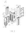
FIG. 3 is a partial, exploded, isometric view of the lathe feeding mechanism and the scraping feeding mechanism ofFIG. 2 . -
FIG. 4 is an exploded, isometric view of the lathe feeding mechanism ofFIG. 3 . -
FIG. 5 is an isometric view of a metallic member to be machined. -
FIG. 6 is a sectional view of the metallic member ofFIG. 5 , taken along line VI-VI ofFIG. 5 . -
FIG. 7 is a flow chart of a first embodiment of the method for machining the metallic member. -
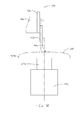
FIG. 8 is a schematic view of a second embodiment of the machine with a part thereof removed. -
FIGS. 1 and2 show a first embodiment of amachine 100 adopting a scraping method for machining a metallic member 300 (seeFIG. 5 ). Themachine 100 includes amachine support 10, aworktable 20, a movingdevice 30, alathe feeding mechanism 40, ascraping feeding mechanism 50, and acontroller 60. Theworktable 20 holds a workpiece in place and is supported by themachine support 10. The movingdevice 30 is movably positioned on themachine support 10 above theworktable 20. Thelathe feeding mechanism 40 and thescraping feeding mechanism 50 are arranged side by side and slidably mounted on the movingdevice 30. Thecontroller 60 is electrically connected to theworktable 20, themoving device 30, thelathe feeding mechanism 40, and thescraping feeding mechanism 50 for controlling themachine 100. Under the control of thecontroller 60, the movingdevice 30 can be driven to move with thelathe feeding mechanism 40 and thescraping feeding mechanism 50, such that thelathe feeding mechanism 40 and thescraping feeding mechanism 50 can be driven three-dimensionally along Cartesian coordinates, that is, along the X, the Y, and the Z axes. - The
machine support 10 includes abase 11 and a pair ofsupport bodies 13 positioned on thebase 11. The pair ofsupport bodies 13 is parallel to each other and arranged apart from each other. Eachsupport body 13 includes a first slidingrail 131 on a surface away from thebase 11. In the illustrated embodiment, the first slidingrail 131 extends substantially parallel to the X-axis (a first direction). - The
worktable 20 is rotatably positioned on thebase 11 between the twosupport bodies 13. Theworktable 20 includes a pair ofmounting bases 21, a first rotatingmember 23, a rotatingshaft 25, and a second rotatingmember 27. The pair ofmounting bases 21 is located in the middle portion of thebase 11, in parallel. The pair ofmounting bases 21 is located between the twosupport bodies 13. The first rotatingmember 23 is mounted on onemounting base 21. The rotatingshaft 25 interconnects the first rotatingmember 23 and the other onemounting base 21. The first rotatingmember 23 is capable of rotating the rotatingshaft 25 around an α axis. The α axis is parallel to the Y-axis but is not co-linear (a second direction). The second rotatingmember 27 is positioned on a middle portion of the rotatingshaft 25, and capable of rotating themetallic member 300 placed thereupon around an β axis. The β axis is parallel to the Z-axis (a third direction) but is not co-linear. The first rotatingmember 23 and the second rotatingmember 27 are electrically connected to thecontroller 60. In the illustrated embodiment, the first rotatingmember 23 and the second rotatingmember 27 are direct drive motors. - The moving
device 30 is slidably mounted on the pair ofsupport bodies 13 and located above theworktable 20. Themoving device 30 includes across beam 31, a pair ofsliding bases 33, a pair offirst driving mechanisms 35, and asecond driving mechanism 37. The extending direction of thecross beam 31 is substantially parallel to the Y-axis. Opposite ends of thecross beam 31 are slidably positioned on thesupport bodies 13. Thecross beam 31 includes a pair of second slidingrails 311 positioned on a side surface and extending substantially parallel to the Y-axis. The pair ofsliding bases 33 is installed on the opposite ends of thecross beam 31 to slidably connect with the first slidingrail 131. Thefirst driving mechanism 35 is mounted on a surface of thesliding base 33 away from thecross beam 31 and located adjacent to an end of the first slidingrail 131. The pair offirst driving mechanisms 35 is employed to drive thecross beam 31 to move along the X-axis direction. - The
second driving mechanism 37 is mounted on thecross beam 31 to drive thelathe feeding mechanism 40 and thescraping feeding mechanism 50 to move along the second slidingrails 311. Thefirst driving mechanisms 35 and thesecond driving mechanism 37 are electrically connected to thecontroller 60. In the illustrated embodiment, thefirst driving mechanisms 35 and thesecond driving mechanism 37 are linear motors with wonderful performance. In other embodiments, thefirst driving mechanisms 35 and thesecond driving mechanism 37 may be other drivers, such as hydraulic cylinders or rams. The number of thefirst driving mechanisms 35, and thesecond driving mechanism 37 may be set according to the application. -
FIGS. 3 to 4 show that thelathe feeding mechanism 40 is slidably positioned on thecross beams 31. Thelathe feeding mechanism 40 includes a sliding saddle 41 (seeFIG. 2 ), a mounting seat 43, atool holder 45, a pair offeeding assemblies 47, and alathe tool 49. The slidingsaddle 41 is assembled to the cross beams 31 and movably engages with the pair of second sliding rails 311. The slidingsaddle 41 is driven by thesecond driving mechanism 37 to slide along the Y-axis direction together with thelathe feeding mechanism 40 and thescraping feeding mechanism 50. The mounting seat 43 is fitted to the slidingsaddle 41 away from thecross beam 31 and equipped with four guidingrails 413 extending along the Z-axis direction. The four guidingrails 413 are divided in two sets spaced from each other in pairs. The slidingsaddle 41 further includes amounting block 415 adjacent to thebase 11. The mountingblock 415 is located between the two sets of guidingrails 413. The mounting seat 43 is assembled to the slidingsaddle 41 and spaced from the four guidingrails 413. - The mounting seat 43 includes a
frame 431 and two mountingboards 433 assembled to opposite sides of theframe 431. Theframe 431 includes afirst side wall 4311 and asecond side wall 4313. Thefirst side wall 4311 and thesecond side wall 4313 are positioned substantially parallel to each other and cooperatively define a receivingspace 4315. Thefirst side wall 4311 is slidably connected with the slidingsaddle 41. Twoseparate guiding portions 4317 protrude from an inner surface of thefirst side wall 4311 facing toward thesecond side wall 4313 and extending substantially parallel to the Z-axis. A throughgroove 4318 is defined in thesecond side wall 4313 and extends along a direction substantially parallel to the Z-axis corresponding to the guidingportions 4317. Two slidingportions 4319 protrude from an outer surface of thesecond side wall 4313 at two sides of the throughgroove 4318. In the illustrated embodiment, the slidingportions 4319 are sliding rails, and theframe 431 is integrally formed. The two mountingboards 433 are installed on opening sides of theframe 431. Each mountingboard 433 is connected substantially perpendicularly to thefirst wall 4311 and thesecond side wall 4313 to close the two opening sides of theframe 431. - The
tool holder 45 slidably connects with the mounting seat 43. Thetool holder 45 is substantially "T" shaped, and includes a main body 451 and a sliding board 453 protruding substantially perpendicularly from the main body 451. The main body 451 is a bar of material tapering at both ends, and positioned outside of the mounting seat 43. Two distanced holdingportions 4511 are positioned on a surface of the main body 451 facing the sliding board 453. The two holdingportions 4511 slidably engage with the pair of slidingportions 4319 of the mounting seat 43. The sliding board 453 passes through the throughgroove 4318 and is slidably assembled to the two guidingportions 4317, dividing the receivingspace 4315 into two parts. - The pair of
feeding assemblies 47 is mounted in the mounting seat 43, and includes twodrivers 471 electrically connected to thecontroller 60. The twodrivers 471 are capable of driving thetool holder 45 into reciprocating motion at high speed along the direction of the Z-axis, relative to the guidingportions 4317 and the slidingportions 4319. The twodrivers 471 are received in the receivingspace 4315 and positioned on two sides of the sliding board 453. In the illustrated embodiment, thedrivers 471 are linear motors. Eachdriver 471 includes a forcer 4711 and astator 4713. Each forcer 4711 is fixed to a surface of each of the mountingboards 433. The sliding board 453 is positioned between the two forcers 4711. The twostators 4713 are positioned on the opposite surfaces of the sliding board 453. In other embodiments, the number ofdrivers 471 may be set according to application. For example, the twodrivers 471 can replace a more powerful single driver, or three or more drivers can be positioned to drive thetool holder 45 to maximize the available power, and the assembly of the drivers is simpler. - The
lathe tool 49 is fixedly assembled to the main body 451 of thetool holder 4511 adjacent to thebase 11. - The
scraping feeding mechanism 50 includes alinear driving assembly 53, a linkingboard 54, a fixingseat 55, a mountingbase 56, arotatable driving member 57 and ascraping cutter 59. Thelinear driving assembly 53 includes a drivingmember 531, ascrew leading rod 533, and anut 535. The drivingmember 531 is mounted on the sliding saddle 43 above thecross beam 31. Thescrew leading rod 533 interconnects the drivingmember 531 and the mountingblock 415. Thenut 535 is sleeved on thescrew leading rod 533 and engages with thescrew leading rod 533. The linkingboard 54 is slidably assembled to the two sets of guidingrails 413 and fixed to thenut 535. The fixingseat 55 is mounted on an end of the linkingboard 54 adjacent to thebase 11. The mountingbase 56 is mounted on an end of the linkingboard 54 opposite to the fixingseat 55. The rotatable drivingmember 57 extends through the fixingseat 55 and the mountingbase 56, and is fittingly supported by the fixingseat 55. Thescraping cutter 59 is mounted on an end of therotatable driving member 57 adjacent to thebase 11. - The driving
member 531 is capable of rotating thescrew leading rod 533 and drives the linkingboard 54, therotatable driving member 57, and thescraping cutter 59 to slide along Z-axis direction. The rotatable drivingmember 57 is capable of rotating thescraping cutter 59. Thescraping cutter 59 is driven by thecross beam 31 to move along the X-axis direction or the Y-axis direction, and driven by the linear drivingassembly 53 to move along Z-axis direction. - In assembly, the
worktable 20 is positioned between the twosupport bodies 13. Thecross beam 31 is installed on the twosupport bodies 13 via the pair of slidingbases 33. The pair offirst driving mechanisms 35, and thesecond driving mechanism 37 are mounted on thebase 11 and thecross beam 31 respectively. Thelathe feeding mechanism 40 and thescraping feeding mechanism 50 are mounted to thecross beam 31 side by side. Theworktable 20, the movingdevice 30, thelathe feeding mechanism 40, and thescraping feeding mechanism 50 are electrically connected to thecontroller 60. -
FIGS. 5 and6 shows that themetallic member 300 to be machined is a housing of a tablet computer or a mobile phone. Themetallic member 300 is substantially rectangular and hollow, and includes atop portion 301 and aperipheral sidewall 303 extending from a peripheral edge of thetop portion 301. Thetop portion 301 has a curved surface with a relatively greater surface area than that of theperipheral sidewall 303. In the embodiment, theperipheral sidewall 303 has fourside surfaces 3031 arranged in order and every two of theadjacent side surfaces 3031 are connected by acorner 3033. The fourside surfaces 3031 are substantially flat surfaces, eachcorner 3033 interconnects two adjacent side surfaces 3031. Theperipheral sidewall 303 further includes anend edge 305 away from thetop portion 301. -
FIG. 7 shows that a method for machining the metallic member includes steps as follows: - In step S101: a
machine 100 is provided, themachine 100 includes aworktable 20, alathe feeding mechanism 40, and ascraping feeding mechanism 50, thelathe feeding mechanism 40 includes alathe tool 49, and thescraping feeding mechanism 50 includes ascraping cutter 59. In the embodiment, themachine 100 is provided as previously described. - In step S102: a
metallic member 300 is placed and held on theworktable 20 of themachine 100. Themetallic member 300 includes atop portion 301 and aperipheral sidewall 303 extending from a peripheral edge of thetop portion 301, theperipheral sidewall 303 includes anend edge 305 away from thetop portion 301. - In step S103: the
second driving mechanism 37 drives thelathe feeding mechanism 40 to move along the Y-axis, thereby positioning thelathe tool 49 at an original position above themetallic member 300. In step S104: the second rotatingmember 27 rotates themetallic member 300 around the β axis; - In step S105: the
lathe feeding mechanism 40 drives thelathe tool 49 to move along the Z-axis reciprocally with a high frequency to machine thetop portion 301 of themetallic member 300 according to the depth of cutting required for each machining portion of thetop portion 301, thereby machining the rotarymetallic member 300 circumferentially. - In step S106: the moving
device 30 moves thelathe feeding mechanism 40 along the X-axis to enable thelathe tool 49 to radially machine thetop portion 301 of themetallic member 300 . - In step S107: the second rotating
member 27 is held to stop rotating, and themetallic member 300 stops rotating, and thelathe tool 49 stops working. - In step S108: the scraping
feeding mechanism 50 drives thescraping cutter 59 to contact theperipheral sidewall 303 of themetallic member 300. In detail, firstly, the pair offirst driving mechanisms 35 drives thecross beam 31 to slide along the X-axis, and thesecond driving mechanism 37 drives thescraping feeding mechanism 50 to move along the Y-axis, such that thescraping cutter 59 moves toward one first slidingrail 131 and arrives at a position above an end of oneside surface 3031 of theperipheral sidewall 303. Secondly, the linear drivingassembly 53 drives thescraping cutter 59 to slide along the two sets of guidingrails 413 until thescraping cutter 59 meets theperipheral sidewall 303 of themetallic member 300. - In step S109: the scraping
feeding mechanism 50 moves along a predetermined path, and simultaneously controls a feeding of thescraping cutter 59 relative to themetallic member 300, thereby machining theperipheral sidewall 303. In detail, the pair offirst driving mechanisms 35 drives thecross beam 31 to slide along the X-axis to enable thescraping cutter 59 to scrap the oneside surface 3031 of theperipheral sidewall 303. When thescraping cutter 59 arrives at thecorner 3033, thescraping cutter 59 is driven by the pair offirst driving mechanisms 35 and thesecond driving mechanism 37 to adjust a feeding direction of thescraping cutter 59. The rotatable drivingmember 57 rotates thescraping cutter 59 to enable thescraping cutter 59 to scrape thecorner 3033 along a tangent line of the outer surface of thecorner 3033. The second rotatingmember 27 rotates the metallic member 300 a certain angle, the movingdevice 30 drives thescraping feeding mechanism 50 to enable thescraping cutter 59 to scrape thenext side surface 3031 along a straight line. In other embodiment, the second rotatingmember 27 continously rotates themetallic member 300 around the β axis, thescraping feeding mechanism 50 is moved by the movingdevice 30 to move along themetallic member 300 in a straight line, and simultaneously controlling a feed of thescraping cutter 59. - In step S110: the
worktable 20 rotates themetallic member 300 to enable theend edge 305 of theperipheral sidewall 303 to face thescraping cutter 59, thescraping feeding mechanism 50 chamfers theend edge 305 along a predetermined path, and simultaneously controls a feeding of thescraping cutter 59 relative to themetallic member 300. In the embodiment, the step S110 includes the sub-steps as follows: - (1) the first rotating
member 23 rotates themetallic member 300 along the α axis upward to enable theend edge 305 on oneside surface 3031 parallel to thecross beam 31 to face thescraping cutter 59. - (2) the
scraping feeding mechanism 50 chamfers theend edge 305 along theend edge 305, and simultaneously controls a movement of thescraping cutter 59 relative to themetallic member 300 - (3) When the
scraping cutter 59 comes to thecorner 3033, thescraping cutter 59 is driven by the pair offirst driving mechanisms 35 and thesecond driving mechanism 37 to adjust a movement direction of thescraping cutter 59. The rotatable drivingmember 57 rotates thescraping cutter 59 to enable thescraping cutter 59 to scrap thecorner 3033 along a tangent line of the outer surface of thecorner 3033. - (4) The
scraping cutter 59 stops working and is moved by the movingdevice 30 away from themetallic member 300. - (5) The first rotating
member 23 rotates themetallic member 300 along the α axis downward. The second rotatingmember 27 rotates themetallic member 300 along the β axis about 90 or 180 degrees to change position of themetallic member 300 relative to thescraping cutter 59, until thenext side surface 3031 adjacent to theside surface 3031 which has the scrapedend edge 305 is parallel to thecross beam 31. - (6) The first rotating
member 23 rotates themetallic member 300 along the α axis upward to enable theend edge 305 on thenext side surface 3031 to face thescraping cutter 59, thescraping cutter 59 is moved by the movingdevice 30 to resist themetallic member 300 and chamber theend edge 305. - (7) the
scraping cutter 59 chamfering the end edges 305 on the side surfaces 3031 one by one, thereby accomplishing chamfering themetallic member 300. - When a
multi-axis worktable 20 is provided, thescraping cutter 59 may chamfer theend edge 305 along a predetermined path with intermittent contact and interruption, such that theend edge 305 on the fourside surfaces 3031 is chamfered at one time. That is, theworktable 20 is capable of rotating along multiple axis to enable thescraping cutter 59 to contact theend edge 305 all the times. - When only the
peripheral sidewall 303 of themetallic member 300 needs to be machined,step 103 to step 107 may be omitted. Thescraping feeding mechanism 50 chamfers theend edge 305 of themetallic member 300 first and then carries out scraping of theperipheral sidewall 303. - In
step 110, thescraping cutter 59 is not limited to chamfering theend edge 305, it may be employed to machine other portions of themetallic member 300, amulti-axis worktable 20 may rotate themetallic member 300 along multiple axis such as theaaxis, and theβaxis to cooperate with thescraping cutter 59. - In other embodiments, the
step 110 of chamfering theend edge 305 can be omitted in the method when theend edge 305 need not be chamfered. - The
scraping feeding mechanism 50 may scrape theperipheral sidewall 303 and chamfers theend edge 305 of themetallic member 300 first, then thelathe feeding mechanism 40 drives thelathe tool 49 to machine thetop portion 301 of themetallic member 300. In the scraping process, thescraping feeding mechanism 50 may just scrap the sidewall. - The sliding
saddle 41, the mounting seat 43, thetool holder 45 may be omitted. Other driving assemblies assembled to the pair of second guiding rails 31 may substitute for the pair offeeding assemblies 47. The driving assembly is capable of directly reciprocating thelathe tool 49 along the Z direction at a high speed. - The
scraping feeding mechanism 50 may not be assembled to the slidingsaddle 41, but assembled to a sliding plate (not shown) slidably mounted on the pair of second guiding rails 311, such that thelathe feeding mechanism 40 and thescraping feeding mechanism 50 may be controlled independently. - The driving
member 531, thescrew leading rod 533, and thenut 535 may be substituted by other driving assemblies, such as a linear cylinder. The linear cylinder is assembled to the pair of second guiding rails 311. The rotatable drivingmember 57 is mounted on an output shaft of the linear cylinder. Accordingly, the linkingboard 54 of thescraping feeding mechanism 50 may be omitted. - The
worktable 20 may include the second rotatingmember 27 only, the second rotatingmember 27 is assembled to thebase 11, and rotates around theβaxis only. Theworktable 20 may be a multi-axis worktable, and rotates themetallic member 300 along a plurality of axis to enable a multi-workstations machining. -
FIG. 8 shows a second embodiment ofmachine 200. In the second embodiment, themachine 20 is employed in a second method for machining themetallic member 300. Themachine 200 is similar to themachine 100 in structure, save that a sliding saddle 41a is slidably assembled to a cross beam 31 a, and a secondrotating member 27a is mounted on a rotating shaft 25a. Themetallic member 300 is placed and held on the second rotatingmember 27a. The difference between themachines 100/200 is that, a mountingseat 43a of themachine 200 is slidably mounted on the sliding saddle 41a and capable of sliding along the Z1-axis direction relative to the sliding saddle 41 a, and alathe tool 49 is slidably mounted on the mountingseat 43a. - When the
lathe feeding mechanism 40 is to machine thetop portion 301 of themetallic member 300, the pair offirst driving mechanisms 35 drive thecross beam 31 to slide along the X-axis, and thesecond driving mechanism 37 drives thelathe feeding mechanism 40 to move along the Y-axis, such that thelathe tool 49 arrives at an original position above theworktable 20 for machining. The original position is located at a middle of a side of thetop portion 301. Then the mountingseat 43a drives thelathe tool 49 to move downwardly along the Z1-axis to reach a preset position near themetallic member 300. Finally, the pair offeeding assemblies 47 drives thelathe tool 49 to move reciprocate at a high speed along the Z-axis according to the depth of cutting required for each machining portion of thetop portion 301, to machine the rotarymetallic member 300 circumferentially. Because the mountingseat 43a can slide along the Z1-aixs to place thelathe tool 49 at the preset position, a reciprocating distance of movement of thelathe tool 49 relative to themetallic member 300 can be reduced, thereby enhancing a reaction response of thelathe tool 49. - Accordingly, in the second embodiment of the method for machining the
metallic member 300, after driving thecross beam 31 to slide along the Y-axis by thesecond driving mechanisms 37, a sub-step of moving the mountingseat 43a downward along the Z1-axis direction to reach a preset position is interposed. - The
scraping feeding mechanism 50 scraps theperipheral sidewall 303 and chamfers theend edge 305 of themetallic member 300 before thelathe feeding mechanism 40 machines thetop portion 301. Thescraping feeding mechanism 50 is not assembled to the slidingsaddle 41, but is assembled to a sliding plate (not shown) slidably mounted on the pair of second guiding rails 311, such that thelathe feeding mechanism 40 and thescraping feeding mechanism 50 may be controlled independently. - The moving
device 30 is capable of moving thelathe feeding mechanism 40 along X/Y-axis directions, and thelathe feeding mechanism 40 is capable of driving thelathe tool 49 along the Z-axis direction reciprocating at a high speed. Such that a feed depth along the Z-axis direction on themetallic member 300 circumferentially is different, thereby a 3D curve surface is produced on thetop portion 301. Thescraping feeding mechanism 50 scraps theperipheral sidewall 303 and chamfers theend edge 305 after thetop portion 301 is machined. Theworktable 20 is capable of rotating themetallic member 300 to match the feed of thelathe feeding mechanism 40, and thelathe feeding mechanism 40 is capable of moving along the Y-axis direction, such that a uninterrupted machining is achieved. The finish oftop portion 301 and theperipheral sidewall 303 of themetallic member 300 is enhanced, and the machining process saves time. Thescraping cutter 59 chamfers thecorner 3033 along the tangent line, such that a finish is enhanced. Theworktable 20 is capable of rotating along the α axis and theβ axis to facilitate thescraping cutter 59 to machine themetallic member 300, it is convenient. - While the present disclosure has been described with reference to particular embodiments, the description is illustrative of the disclosure and is not to be construed as limiting the disclosure. Therefore, various modifications can be made to the embodiments by those of ordinary skill in the art without departing from the true spirit and scope of the disclosure, as defined by the appended claims.
Claims (10)
- A machining method for machining metallic member using lathing and scraping, comprising:(1) providing a machine comprising a machine support, a worktable, a moving device, a lathe feeding mechanism, and a scraping feeding mechanism, wherein the worktable is positioned on the machine support; the moving device is slidably assembled to the machine support along a first direction and located above the worktable, the lathe feeding mechanism and the scraping feeding mechanism are slidably assembled to the moving device along a second direction perpendicular to the first direction, the lathe feeding mechanism comprises at least one feeding assembly and a lathe tool connected to the at least one feeding assembly, the at least one feeding assembly is configured for driving the lathe tool to move along a third direction substantially perpendicular to the first and second direction reciprocally, the scraping feeding mechanism comprises a scraping cutter and is configured for driving the scraping cutter to move along the third direction;(2) positioning a metallic member on the worktable, the metallic member comprising a top portion and a peripheral sidewall extending from a peripheral edge of the top portion, the peripheral sidewall comprising an end edge away from the top portion;(3) moving the lathe tool by the moving device to resist the top portion of the metallic member;(4) applying the worktable to rotate with the metallic member along a first axis along an axis parallel to the third direction;(5) controlling the lathe tool to move backwards and forwards toward the metallic member to machine the top portion of the metallic member circumferentially;(6) moving the lathe tool by the moving device along a predetermined path relative to the worktable to machine curved surfaces of the top portion of the metallic member;(7) holding the metallic member to stop rotate, and moving the lathe tool away from the metallic member;(8) driving the scraping cutter by the moving device to contact the peripheral sidewall of the metallic member; and(9) moving the scraping cutter along a predetermined path to scrap the peripheral sidewall of the metallic member, simultaneously controlling a feed of the scraping cutter relative to the metallic member.
- The method of claim 1, wherein the scraping feeding mechanism further comprises a rotatable driving member configured for driving the scraping cutter to rotate along an axis parallel to the third direction, the peripheral sidewall comprises a plurality of side surfaces arranged in order and adjacent two of the plurality of side surfaces is connected by a corner, step (9) further comprises when the scraping cutter arrives at the corner, the rotatable driving member rotates the scraping cutter to enable the scraping cutter scraping the corner along a tangent line of an outer surface of the corner, until the scraping cutter arrives at an adjacent side surface to the side surface that has been scraped, and followed by repeating the machining steps on the adjacent side surface.
- The method of any of claims 1 and 2, wherein the machining method further comprises a step (10), the step (10) comprises applying the worktable to rotate the metallic member along the first axis and a second axis parallel to the second direction to enable the end edge of the peripheral sidewall to face the scraping cutter, and chamfering the end edge by the scraping cutter along a predetermined path, simultaneously controlling a feed of the scraping cutter relative to the metallic member.
- The method of claim 3, wherein the step (10) further comprises: rotating the metallic member by the worktable along the second axis upward; chamfering the end edge along the end edge; when the scraping cutter arriving at the corner, driving the scraping cutter by the moving device to adjust a feed direction of the scraping cutter, and rotating the scraping cutter by rotatable driving members to enable the scraping cutter to scrap the corner along the tangent line of the outer surface of the corner; the scraping cutter stopping working and moving the scraping cutter by the moving device away from the metallic member; rotating the metallic member by the worktable along first axis and second axis for a certain angle, moving the scraping cutter by the moving device to resist the metallic member and chamfering the end edge; the scraping cutter chamfering the end edges on the side surfaces one by one, thereby accomplishing chamfering the metallic member.
- The method of claim 3, wherein the worktable the worktable is capable of rotating along multi-axis, in the step (10), the worktable rotates the metallic member along multi-axis, the moving device moves the scraping cutter simultaneously to enable the scraping cutter to contact and scrap the end edge all the time.
- The method of any of claims 1 to 5, wherein in the step (9), the worktable remains still, the scraping cutter moves along a predetermined path to scrap the peripheral sidewall of the metallic member.
- The method of any of claims 1 to 6, wherein in the step (9), the worktable rotates the metallic member along the first axis to match with the scraping of the scraping cutter.
- The method of any of claims 1 to 7, wherein in the step (8), when the scraping feeding mechanism arrives at the peripheral sidewall, the scraping feeding mechanism drives the scraping cutter to slide along the third direction to enable the scraping cutter to arrives at a particular position of the peripheral sidewall.
- The method of claims any of claims 1 to 8, wherein the lathe feeding mechanism further comprises a sliding saddle and mounting seat fittingly assembled to the sliding saddle, the sliding saddle is slidably connected to the moving device along the second direction, the feeding assembly is received in the mounting seat, and the lathe tool is slidably mounted on the mounting seat, the scraping feeding mechanism is slidably mounted on the sliding saddle along the third direction and the scraping feeding mechanism is adjacent to the mounting seat.
- The method of claim 9, wherein the scraping feeding mechanism further comprises a linear driving assembly and a linking board, the linear driving assembly comprises a driving member, a screw leading rod, and a nut, the driving member is mounted on the sliding saddle, the sliding saddle comprises a mounting block, the screw leading rod rotatably interconnects the driving member and the mounting block, the nut is sleeved on and engages with the screw leading rod, the linking board is fixed to the nut and slidably engages with the sliding saddle, the rotatable driving member is mounted on the linking board.
Applications Claiming Priority (2)
| Application Number | Priority Date | Filing Date | Title |
|---|---|---|---|
| CN201210553795.XA CN103878589B (en) | 2012-12-19 | 2012-12-19 | Metalwork processing method |
| CN201210554320.2A CN103878591B (en) | 2012-12-19 | 2012-12-19 | Metalwork processing method |
Publications (3)
| Publication Number | Publication Date |
|---|---|
| EP2745962A2 true EP2745962A2 (en) | 2014-06-25 |
| EP2745962A3 EP2745962A3 (en) | 2015-04-15 |
| EP2745962B1 EP2745962B1 (en) | 2021-02-10 |
Family
ID=49766971
Family Applications (1)
| Application Number | Title | Priority Date | Filing Date |
|---|---|---|---|
| EP13197294.5A Active EP2745962B1 (en) | 2012-12-19 | 2013-12-13 | Method for machining metallic member using lathing and scraping |
Country Status (1)
| Country | Link |
|---|---|
| EP (1) | EP2745962B1 (en) |
Family Cites Families (4)
| Publication number | Priority date | Publication date | Assignee | Title |
|---|---|---|---|---|
| JP3610485B2 (en) * | 1999-09-20 | 2005-01-12 | 株式会社日立製作所 | Numerically controlled curved surface processing equipment |
| JP5030606B2 (en) * | 2007-01-30 | 2012-09-19 | ヤマザキマザック株式会社 | Machining center |
| DE102009058649A1 (en) * | 2009-12-16 | 2011-06-22 | Adams, Heinz, 66740 | Drilling-milling machine with additional rotary tool slide, rotary holder, turning tool and turntable for turning |
| DE102011105402A1 (en) * | 2011-06-20 | 2012-12-20 | Heinz Adams | Milling, turning, grinding machine for workpiece, has vertically movable vertical milling-turning slide and vertically movable vertical grinding rotary plunger movably vertically installed adjacent to each other on Y-bar slide |
-
2013
- 2013-12-13 EP EP13197294.5A patent/EP2745962B1/en active Active
Non-Patent Citations (1)
| Title |
|---|
| None |
Also Published As
| Publication number | Publication date |
|---|---|
| EP2745962A3 (en) | 2015-04-15 |
| EP2745962B1 (en) | 2021-02-10 |
Similar Documents
| Publication | Publication Date | Title |
|---|---|---|
| US9409268B2 (en) | Machine tool with lathe tool and milling cutter | |
| US9421651B2 (en) | Machine tool with lathe tool and scraping cutter | |
| US9718153B2 (en) | Method for machining metallic member using lathing and scraping | |
| US9630278B2 (en) | Method for machining metallic member using lathing and scraping | |
| US9381580B2 (en) | Milling method for machining metallic member | |
| US9550257B2 (en) | Method for machining metallic member using lathing and milling | |
| US9527174B2 (en) | Method for machining metallic member using lathing and milling | |
| US20140020525A1 (en) | Feeding device and machine tool using the same | |
| US9254542B2 (en) | Machine tool with uninterrupted cutting | |
| EP2745960B1 (en) | Method for machining metallic member using lathing and milling | |
| US9757824B2 (en) | Method for machining metallic member using lathing and scraping | |
| EP2745962B1 (en) | Method for machining metallic member using lathing and scraping | |
| US9238306B2 (en) | Feeding device and machine tool using the same | |
| EP2687308B1 (en) | Lathe for machining curved surfaces |
Legal Events
| Date | Code | Title | Description |
|---|---|---|---|
| PUAI | Public reference made under article 153(3) epc to a published international application that has entered the european phase |
Free format text: ORIGINAL CODE: 0009012 |
|
| 17P | Request for examination filed |
Effective date: 20131213 |
|
| AK | Designated contracting states |
Kind code of ref document: A2 Designated state(s): AL AT BE BG CH CY CZ DE DK EE ES FI FR GB GR HR HU IE IS IT LI LT LU LV MC MK MT NL NO PL PT RO RS SE SI SK SM TR |
|
| AX | Request for extension of the european patent |
Extension state: BA ME |
|
| PUAL | Search report despatched |
Free format text: ORIGINAL CODE: 0009013 |
|
| AK | Designated contracting states |
Kind code of ref document: A3 Designated state(s): AL AT BE BG CH CY CZ DE DK EE ES FI FR GB GR HR HU IE IS IT LI LT LU LV MC MK MT NL NO PL PT RO RS SE SI SK SM TR |
|
| AX | Request for extension of the european patent |
Extension state: BA ME |
|
| RIC1 | Information provided on ipc code assigned before grant |
Ipc: B23B 5/36 20060101AFI20150310BHEP |
|
| R17P | Request for examination filed (corrected) |
Effective date: 20151014 |
|
| RBV | Designated contracting states (corrected) |
Designated state(s): AL AT BE BG CH CY CZ DE DK EE ES FI FR GB GR HR HU IE IS IT LI LT LU LV MC MK MT NL NO PL PT RO RS SE SI SK SM TR |
|
| STAA | Information on the status of an ep patent application or granted ep patent |
Free format text: STATUS: EXAMINATION IS IN PROGRESS |
|
| 17Q | First examination report despatched |
Effective date: 20190329 |
|
| GRAP | Despatch of communication of intention to grant a patent |
Free format text: ORIGINAL CODE: EPIDOSNIGR1 |
|
| STAA | Information on the status of an ep patent application or granted ep patent |
Free format text: STATUS: GRANT OF PATENT IS INTENDED |
|
| INTG | Intention to grant announced |
Effective date: 20200903 |
|
| RAP1 | Party data changed (applicant data changed or rights of an application transferred) |
Owner name: FUXIANG PRECISION INDUSTRIAL (KUNSHAN) CO., LTD. |
|
| GRAS | Grant fee paid |
Free format text: ORIGINAL CODE: EPIDOSNIGR3 |
|
| GRAA | (expected) grant |
Free format text: ORIGINAL CODE: 0009210 |
|
| STAA | Information on the status of an ep patent application or granted ep patent |
Free format text: STATUS: THE PATENT HAS BEEN GRANTED |
|
| AK | Designated contracting states |
Kind code of ref document: B1 Designated state(s): AL AT BE BG CH CY CZ DE DK EE ES FI FR GB GR HR HU IE IS IT LI LT LU LV MC MK MT NL NO PL PT RO RS SE SI SK SM TR |
|
| REG | Reference to a national code |
Ref country code: GB Ref legal event code: FG4D |
|
| REG | Reference to a national code |
Ref country code: AT Ref legal event code: REF Ref document number: 1360030 Country of ref document: AT Kind code of ref document: T Effective date: 20210215 Ref country code: CH Ref legal event code: EP |
|
| REG | Reference to a national code |
Ref country code: DE Ref legal event code: R096 Ref document number: 602013075601 Country of ref document: DE |
|
| REG | Reference to a national code |
Ref country code: IE Ref legal event code: FG4D |
|
| REG | Reference to a national code |
Ref country code: LT Ref legal event code: MG9D |
|
| REG | Reference to a national code |
Ref country code: NL Ref legal event code: MP Effective date: 20210210 |
|
| PG25 | Lapsed in a contracting state [announced via postgrant information from national office to epo] |
Ref country code: LT Free format text: LAPSE BECAUSE OF FAILURE TO SUBMIT A TRANSLATION OF THE DESCRIPTION OR TO PAY THE FEE WITHIN THE PRESCRIBED TIME-LIMIT Effective date: 20210210 Ref country code: PT Free format text: LAPSE BECAUSE OF FAILURE TO SUBMIT A TRANSLATION OF THE DESCRIPTION OR TO PAY THE FEE WITHIN THE PRESCRIBED TIME-LIMIT Effective date: 20210611 Ref country code: HR Free format text: LAPSE BECAUSE OF FAILURE TO SUBMIT A TRANSLATION OF THE DESCRIPTION OR TO PAY THE FEE WITHIN THE PRESCRIBED TIME-LIMIT Effective date: 20210210 Ref country code: FI Free format text: LAPSE BECAUSE OF FAILURE TO SUBMIT A TRANSLATION OF THE DESCRIPTION OR TO PAY THE FEE WITHIN THE PRESCRIBED TIME-LIMIT Effective date: 20210210 Ref country code: GR Free format text: LAPSE BECAUSE OF FAILURE TO SUBMIT A TRANSLATION OF THE DESCRIPTION OR TO PAY THE FEE WITHIN THE PRESCRIBED TIME-LIMIT Effective date: 20210511 Ref country code: BG Free format text: LAPSE BECAUSE OF FAILURE TO SUBMIT A TRANSLATION OF THE DESCRIPTION OR TO PAY THE FEE WITHIN THE PRESCRIBED TIME-LIMIT Effective date: 20210510 Ref country code: NO Free format text: LAPSE BECAUSE OF FAILURE TO SUBMIT A TRANSLATION OF THE DESCRIPTION OR TO PAY THE FEE WITHIN THE PRESCRIBED TIME-LIMIT Effective date: 20210510 |
|
| REG | Reference to a national code |
Ref country code: AT Ref legal event code: MK05 Ref document number: 1360030 Country of ref document: AT Kind code of ref document: T Effective date: 20210210 |
|
| PG25 | Lapsed in a contracting state [announced via postgrant information from national office to epo] |
Ref country code: SE Free format text: LAPSE BECAUSE OF FAILURE TO SUBMIT A TRANSLATION OF THE DESCRIPTION OR TO PAY THE FEE WITHIN THE PRESCRIBED TIME-LIMIT Effective date: 20210210 Ref country code: NL Free format text: LAPSE BECAUSE OF FAILURE TO SUBMIT A TRANSLATION OF THE DESCRIPTION OR TO PAY THE FEE WITHIN THE PRESCRIBED TIME-LIMIT Effective date: 20210210 Ref country code: PL Free format text: LAPSE BECAUSE OF FAILURE TO SUBMIT A TRANSLATION OF THE DESCRIPTION OR TO PAY THE FEE WITHIN THE PRESCRIBED TIME-LIMIT Effective date: 20210210 Ref country code: RS Free format text: LAPSE BECAUSE OF FAILURE TO SUBMIT A TRANSLATION OF THE DESCRIPTION OR TO PAY THE FEE WITHIN THE PRESCRIBED TIME-LIMIT Effective date: 20210210 Ref country code: LV Free format text: LAPSE BECAUSE OF FAILURE TO SUBMIT A TRANSLATION OF THE DESCRIPTION OR TO PAY THE FEE WITHIN THE PRESCRIBED TIME-LIMIT Effective date: 20210210 |
|
| PG25 | Lapsed in a contracting state [announced via postgrant information from national office to epo] |
Ref country code: IS Free format text: LAPSE BECAUSE OF FAILURE TO SUBMIT A TRANSLATION OF THE DESCRIPTION OR TO PAY THE FEE WITHIN THE PRESCRIBED TIME-LIMIT Effective date: 20210610 |
|
| PG25 | Lapsed in a contracting state [announced via postgrant information from national office to epo] |
Ref country code: SM Free format text: LAPSE BECAUSE OF FAILURE TO SUBMIT A TRANSLATION OF THE DESCRIPTION OR TO PAY THE FEE WITHIN THE PRESCRIBED TIME-LIMIT Effective date: 20210210 Ref country code: AT Free format text: LAPSE BECAUSE OF FAILURE TO SUBMIT A TRANSLATION OF THE DESCRIPTION OR TO PAY THE FEE WITHIN THE PRESCRIBED TIME-LIMIT Effective date: 20210210 Ref country code: EE Free format text: LAPSE BECAUSE OF FAILURE TO SUBMIT A TRANSLATION OF THE DESCRIPTION OR TO PAY THE FEE WITHIN THE PRESCRIBED TIME-LIMIT Effective date: 20210210 Ref country code: CZ Free format text: LAPSE BECAUSE OF FAILURE TO SUBMIT A TRANSLATION OF THE DESCRIPTION OR TO PAY THE FEE WITHIN THE PRESCRIBED TIME-LIMIT Effective date: 20210210 |
|
| REG | Reference to a national code |
Ref country code: DE Ref legal event code: R097 Ref document number: 602013075601 Country of ref document: DE |
|
| PG25 | Lapsed in a contracting state [announced via postgrant information from national office to epo] |
Ref country code: SK Free format text: LAPSE BECAUSE OF FAILURE TO SUBMIT A TRANSLATION OF THE DESCRIPTION OR TO PAY THE FEE WITHIN THE PRESCRIBED TIME-LIMIT Effective date: 20210210 Ref country code: DK Free format text: LAPSE BECAUSE OF FAILURE TO SUBMIT A TRANSLATION OF THE DESCRIPTION OR TO PAY THE FEE WITHIN THE PRESCRIBED TIME-LIMIT Effective date: 20210210 Ref country code: ES Free format text: LAPSE BECAUSE OF FAILURE TO SUBMIT A TRANSLATION OF THE DESCRIPTION OR TO PAY THE FEE WITHIN THE PRESCRIBED TIME-LIMIT Effective date: 20210210 Ref country code: RO Free format text: LAPSE BECAUSE OF FAILURE TO SUBMIT A TRANSLATION OF THE DESCRIPTION OR TO PAY THE FEE WITHIN THE PRESCRIBED TIME-LIMIT Effective date: 20210210 |
|
| PLBE | No opposition filed within time limit |
Free format text: ORIGINAL CODE: 0009261 |
|
| STAA | Information on the status of an ep patent application or granted ep patent |
Free format text: STATUS: NO OPPOSITION FILED WITHIN TIME LIMIT |
|
| 26N | No opposition filed |
Effective date: 20211111 |
|
| PG25 | Lapsed in a contracting state [announced via postgrant information from national office to epo] |
Ref country code: AL Free format text: LAPSE BECAUSE OF FAILURE TO SUBMIT A TRANSLATION OF THE DESCRIPTION OR TO PAY THE FEE WITHIN THE PRESCRIBED TIME-LIMIT Effective date: 20210210 |
|
| PG25 | Lapsed in a contracting state [announced via postgrant information from national office to epo] |
Ref country code: SI Free format text: LAPSE BECAUSE OF FAILURE TO SUBMIT A TRANSLATION OF THE DESCRIPTION OR TO PAY THE FEE WITHIN THE PRESCRIBED TIME-LIMIT Effective date: 20210210 |
|
| PG25 | Lapsed in a contracting state [announced via postgrant information from national office to epo] |
Ref country code: IT Free format text: LAPSE BECAUSE OF FAILURE TO SUBMIT A TRANSLATION OF THE DESCRIPTION OR TO PAY THE FEE WITHIN THE PRESCRIBED TIME-LIMIT Effective date: 20210210 |
|
| PG25 | Lapsed in a contracting state [announced via postgrant information from national office to epo] |
Ref country code: IS Free format text: LAPSE BECAUSE OF FAILURE TO SUBMIT A TRANSLATION OF THE DESCRIPTION OR TO PAY THE FEE WITHIN THE PRESCRIBED TIME-LIMIT Effective date: 20210610 |
|
| PG25 | Lapsed in a contracting state [announced via postgrant information from national office to epo] |
Ref country code: MC Free format text: LAPSE BECAUSE OF FAILURE TO SUBMIT A TRANSLATION OF THE DESCRIPTION OR TO PAY THE FEE WITHIN THE PRESCRIBED TIME-LIMIT Effective date: 20210210 |
|
| REG | Reference to a national code |
Ref country code: CH Ref legal event code: PL |
|
| REG | Reference to a national code |
Ref country code: BE Ref legal event code: MM Effective date: 20211231 |
|
| PG25 | Lapsed in a contracting state [announced via postgrant information from national office to epo] |
Ref country code: LU Free format text: LAPSE BECAUSE OF NON-PAYMENT OF DUE FEES Effective date: 20211213 Ref country code: IE Free format text: LAPSE BECAUSE OF NON-PAYMENT OF DUE FEES Effective date: 20211213 |
|
| PG25 | Lapsed in a contracting state [announced via postgrant information from national office to epo] |
Ref country code: BE Free format text: LAPSE BECAUSE OF NON-PAYMENT OF DUE FEES Effective date: 20211231 |
|
| PG25 | Lapsed in a contracting state [announced via postgrant information from national office to epo] |
Ref country code: LI Free format text: LAPSE BECAUSE OF NON-PAYMENT OF DUE FEES Effective date: 20211231 Ref country code: CH Free format text: LAPSE BECAUSE OF NON-PAYMENT OF DUE FEES Effective date: 20211231 |
|
| PG25 | Lapsed in a contracting state [announced via postgrant information from national office to epo] |
Ref country code: HU Free format text: LAPSE BECAUSE OF FAILURE TO SUBMIT A TRANSLATION OF THE DESCRIPTION OR TO PAY THE FEE WITHIN THE PRESCRIBED TIME-LIMIT; INVALID AB INITIO Effective date: 20131213 |
|
| PG25 | Lapsed in a contracting state [announced via postgrant information from national office to epo] |
Ref country code: CY Free format text: LAPSE BECAUSE OF FAILURE TO SUBMIT A TRANSLATION OF THE DESCRIPTION OR TO PAY THE FEE WITHIN THE PRESCRIBED TIME-LIMIT Effective date: 20210210 |
|
| PG25 | Lapsed in a contracting state [announced via postgrant information from national office to epo] |
Ref country code: MK Free format text: LAPSE BECAUSE OF FAILURE TO SUBMIT A TRANSLATION OF THE DESCRIPTION OR TO PAY THE FEE WITHIN THE PRESCRIBED TIME-LIMIT Effective date: 20210210 |
|
| PG25 | Lapsed in a contracting state [announced via postgrant information from national office to epo] |
Ref country code: TR Free format text: LAPSE BECAUSE OF FAILURE TO SUBMIT A TRANSLATION OF THE DESCRIPTION OR TO PAY THE FEE WITHIN THE PRESCRIBED TIME-LIMIT Effective date: 20210210 |
|
| PG25 | Lapsed in a contracting state [announced via postgrant information from national office to epo] |
Ref country code: MT Free format text: LAPSE BECAUSE OF FAILURE TO SUBMIT A TRANSLATION OF THE DESCRIPTION OR TO PAY THE FEE WITHIN THE PRESCRIBED TIME-LIMIT Effective date: 20210210 |
|
| PGFP | Annual fee paid to national office [announced via postgrant information from national office to epo] |
Ref country code: GB Payment date: 20251229 Year of fee payment: 13 |
|
| PGFP | Annual fee paid to national office [announced via postgrant information from national office to epo] |
Ref country code: FR Payment date: 20251230 Year of fee payment: 13 |
|
| PGFP | Annual fee paid to national office [announced via postgrant information from national office to epo] |
Ref country code: DE Payment date: 20251231 Year of fee payment: 13 |