EP2745739A1 - Suspension fitting for a wall mounted cabinet - Google Patents
Suspension fitting for a wall mounted cabinet Download PDFInfo
- Publication number
- EP2745739A1 EP2745739A1 EP13005581.7A EP13005581A EP2745739A1 EP 2745739 A1 EP2745739 A1 EP 2745739A1 EP 13005581 A EP13005581 A EP 13005581A EP 2745739 A1 EP2745739 A1 EP 2745739A1
- Authority
- EP
- European Patent Office
- Prior art keywords
- wall
- wall holder
- suspension device
- support
- furniture
- Prior art date
- Legal status (The legal status is an assumption and is not a legal conclusion. Google has not performed a legal analysis and makes no representation as to the accuracy of the status listed.)
- Granted
Links
- 239000000725 suspension Substances 0.000 title claims description 62
- 239000000463 material Substances 0.000 claims description 7
- 238000011161 development Methods 0.000 description 7
- 230000018109 developmental process Effects 0.000 description 7
- 238000004519 manufacturing process Methods 0.000 description 3
- 229910001209 Low-carbon steel Inorganic materials 0.000 description 2
- 230000006378 damage Effects 0.000 description 2
- 230000007704 transition Effects 0.000 description 2
- 229910000831 Steel Inorganic materials 0.000 description 1
- 229910000746 Structural steel Inorganic materials 0.000 description 1
- 208000027418 Wounds and injury Diseases 0.000 description 1
- 238000005452 bending Methods 0.000 description 1
- 208000014674 injury Diseases 0.000 description 1
- 238000010409 ironing Methods 0.000 description 1
- 239000007769 metal material Substances 0.000 description 1
- 238000009420 retrofitting Methods 0.000 description 1
- 239000010959 steel Substances 0.000 description 1
Images


Classifications
-
- A—HUMAN NECESSITIES
- A47—FURNITURE; DOMESTIC ARTICLES OR APPLIANCES; COFFEE MILLS; SPICE MILLS; SUCTION CLEANERS IN GENERAL
- A47B—TABLES; DESKS; OFFICE FURNITURE; CABINETS; DRAWERS; GENERAL DETAILS OF FURNITURE
- A47B95/00—Fittings for furniture
- A47B95/008—Suspension fittings for cabinets to be hung on walls
Definitions
- the invention relates to a suspension device for furniture, in particular cupboard furniture or the like, with at least one attachable to the furniture mounting member to which at least one support tab is arranged, which is mounted in its position of use in a likewise belonging to the suspension wall bracket, wherein Ausschommeskar are provided, the one have on a base body of the support tab arranged stop projection, which is aligned in the position of use of the support bracket to the wall holder, that accidental unhooking from the wall holder is prevented, wherein the support tab for intentional unhooking in a release position is movable, in which the stopper protrusion out of engagement Wandhalter arrives.
- Such a suspension device for furniture is in the DE 20 2011 001 589 U1 disclosed.
- the suspension device described there prevents unintentional unhooking of the furniture from a wall bracket.
- cabinet furniture in the form of wall cabinets there is a risk that they are unintentionally posted, for example, when a person is under the wall cabinet and straightens, which then leads to the bow-shaped support bracket of the suspension from the wall hook or the wall rail extends. It may cause injury to the person and / or to Damage to the furniture come.
- the suspension device described in the cited document has solved this problem by the fact that are arranged on the support flap suspension securing means comprising a transversely adjustable to the direction of adjustment locking bolt. In the securing position of the adjusting bolt engages under a trained on the wall holder recess portion with counter-stop, whereby the detachment of the support bracket is prevented from the wall hook.
- the object of the invention is to provide a suspension device for furniture of the type mentioned above, which is inexpensive to produce, are provided in the reliable acting Ausitatitechnischssstoff and is easy to handle.
- the suspension device for furniture according to the invention is characterized in that the stop projection is so firmly attached to the support bracket and the support bracket with respect to the wall bracket has such a pivoting freedom that the support tab in unchangeable relative position between the stopper projection and the base body from the use position in the release position is.
- the stop projection engages under the wall bracket in the position of use of the support bracket.
- the stop projection can engage under the lower edge of the wall holder.
- other suitable sections are formed on the wall holder, which can be engaged by the stop projection.
- the wall holder on a Ein vonabrough for suspending the main body of the support tab which also acts as a pivot bearing for the main body of the support bracket.
- the unhooking can thus be done by a pivoting movement of the support bracket relative to the wall bracket, in which the stopper projection is disengaged from the wall bracket.
- the suspension section protrudes forwardly away from the building wall in the mounting position of the wall bracket.
- a gap is thus formed between the building wall and the suspension section, in which a specific section of the support strap can be suspended.
- the main body of the support bracket on a base portion on which the stopper projection is formed in addition to the base portion still has a bracket section for hanging in the wall hook.
- Base section and Ironing section are advantageously integrally formed with each other, so they can be formed with the same in the production of the support bracket.
- the support tab and / or the wall holder made of metal material, preferably steel material, in particular mild steel.
- the bracket portion of the support bracket on two V-shaped mutually arranged stirrup legs of which a suspension leg engages behind the Ein Wegabrough of the wall bracket when hanging.
- the V-shaped configuration of the two stirrup legs forms a pivoting play relative to the wall holder, if the support tab is suspended in the wall holder.
- the bracket portion with its two stirrup legs and the Ein vonabites on the wall bracket can therefore together form a pivot bearing, which allows pivoting of the support bracket for the purpose of the intended Ausriess from the wall bracket.
- the distance between the upper edge of the bracket portion and the stopper projection is greater than the height of the wall bracket. Characterized in that the stopper projection is relatively far away from the pivot point of the support tab, a relatively short pivoting is sufficient so that the stopper projection is disengaged from the wall bracket.
- the stop projection is integrally connected to the base body of the support tab, in particular formed out of the material of the base body.
- the stop projection is attached to the main body attachment.
- the invention further comprises a suspension device having the features of independent claim 9.
- the suspension device according to claim 9 is characterized in that the stopper projection is arranged on the wall holder.
- safety catch means are provided, wherein these comprise a stop projection on the wall holder.
- the stop projection is integrally connected to the wall holder. Conveniently, it is formed out of the material of the wall holder. It can therefore be molded with the same during the production of the wall holder.
- the wall holder has a base section, by means of which it can be fastened to a building wall by means of fastening means. Further, the wall holder has a Ein feelingabêt for suspending the support tab, wherein the stopper projection is formed on the Ein supraabites.
- stop projection protrude transversely from the suspension section and, when the suspension strap is suspended, engage over a stop surface arranged there.
- the stop projection is formed on a separately formed from the wall bracket and fastened to the wall bracket or attached additional part.
- conventional wall mount can be retrofitted.
- the additional part is attached to the base portion of the wall holder, wherein preferably the attachment of the additional part to the wall holder takes place via the same fasteners that are also used for attaching the wall bracket to the building wall.
- the invention further comprises a piece of furniture, in particular cupboard furniture having the features of independent claim 15.
- FIGS. 1 to 3 show a first embodiment of the suspension device 11 according to the invention for furniture.
- the suspension device 11 is suitable, for example, for hanging a cabinet furniture, for example in the form of an upper cabinet.
- the suspension device 11 could also be referred to as a cabinet trailer.
- the function of the hanger 11 as a cabinet hanger should be exemplified when used for hanging a cabinet furniture, although the application is not limited to cabinet furniture.
- the suspension device 11 has a plate-like mounting member 12, which is suitably made of structural steel and which is fastened via fastening holes 13 and with these cooperating fastening means, such as fastening screws, on the outside of the cabinet rear wall.
- the mounting member 12 has a plate-like base portion 14 which is brought into abutment to the cabinet rear wall and is fixed there via the aforementioned mounting holes 13 at this.
- the mounting member 12 has an angle projecting from the fastening part 14 side part 15, which is advantageously formed by bending the overall plate-like mounting member 12.
- mounting pins 16 are arranged, which protrude from the side portion 15 to the outside and are received in the assembled state in correspondingly shaped mounting holes (not shown) on the inside of the cabinet back wall projecting rearwardly portion of the cabinet side wall.
- three mounting lugs 16 lying one above the other in series are shown here. The mounting pins 16 are used to load the cabinet load, the load is distributed to the three mounting pin 16.
- the suspension device 11 comprises a stirrup-like support bracket 17.
- the support bracket 17 has a base body 18, which is adjustably adjustable on the mounting member 12, in particular is stored there at the attachment section.
- a threaded bolt 19 is provided which is adjustably mounted in an opening formed as a threaded bore on the mounting member 12.
- the threaded bolt 19 passes through the support tab 17 in the region of the base body 18.
- the base body 18 is a guide slot 20 which allows a relative movement of the support bracket 17 relative to the threaded bolt 19.
- the threaded bolt 19 further has a bolt head 21 which rests on the upper side of the main body 18.
- the inside width of the guide slot 20 is dimensioned such that the slot wall engages between the bolt head 21 and the first thread of the threaded bolt 19, so that an adjustment of the threaded bolt 19 causes a entrainment of the base body 18 and thus the support bracket 17, whereby the support bracket 17 can be spread apart from the mounting element 12.
- the main body 18 of the support bracket 17 consists essentially of two components, namely a base portion 22, on which the guide slot 20 is formed and a bracket portion 23 for hooking into a wall bracket 24 also belonging to the suspension device 11.
- the bracket portion 23 is configured in the form of a Ein distressbügels and has two V-shaped mutually arranged stirrup legs.
- the wall holder 24 is exemplified in the form of a wall rail.
- the wall rail is also made of mild steel.
- the wall rail has a base portion 25 which has a plurality of mounting holes 26, via which it can be attached to a building wall.
- the wall rail also has a Einitatiabrisk 27 which is integrally connected to the base portion 25 and in the assembled state of the wall rail from the base portion to juts out in front.
- a gap is formed in which a trained as a suspension leg 28 stirrup leg of the bracket portion 23 of the support bracket 17 is added, which engages behind the Einitatiabites 28 of the wall rail.
- the load is therefore transferred from the cabinet furniture substantially via the mounting pin 16 on the mounting member 12 and from there via the support bracket 17 and the bracket portion 23 on the wall rail.
- Aussch are provided which have a stop projection 29 which is aligned in the position of use of the support bracket 17 to the wall rail, that accidental unhooking from the wall rail is prevented.
- the support tab 17 is movable into a release position in which the stopper projection 29 is disengaged from the wall rail.
- the stop projection 29 is arranged on the base body 18 of the support lug 17. As in particular in FIG. 1 shown, the stopper protrusion 29 is disposed at the transition between the base portion 22 and the bracket portion 23 of the support bracket 17.
- the stop projection 29 has, as in particular in FIG. 1 illustrated, two substantially of the support strap transversely to the rear, so in the assembled state of the support bracket to the building wall directed towards stop lugs 30a, 30b, which are suitably integrally connected to the support bracket 17, in particular from the material of the support bracket 17 are formed and therefore in the Production of the support bracket 17 can be formed with the same.
- the distance between the upper edges of the stop lugs 30a, 30b and the lower edge of the bracket portion 23 is greater than the height of the wall rail.
- the stop lugs 30a, 30b thus engage under the base portion 25 of the wall holder 24.
- the stop projection 29 so the two stop lugs 30a, 30b in the securing position. If in this position, as mentioned above, a person is under the wall unit and straighten up, the support bracket 17 could not be unhooked from the wall rail 24, since the two stop lugs 30a, 30b would strike the lower edge of the base portion 25. The support bracket 17 is thus secured against unintentional unhooking from the wall rail.
- FIG. 3 shows that the support bracket 17 can be pivoted so far relative to the wall rail until the suspension leg rests flat against the inside of the vertical wall of the Ein stressedabitess 27.
- This pivoting path causes the Stop projection 29 out of engagement with the wall rail passes, ie the stop lugs 30a, 30b are pivoted so far that they no longer engage under the base portion 25 of the wall holder 24, whereby a detachment of the support bracket together with the cabinet furniture is possible.
- An advantage of the design of the stop projection 29 is that this is so firmly attached to the support bracket 17, and the support bracket with respect to the wall rail has such a pivoting freedom that the support bracket 17 in unchangeable relative position between the stopper projection 29 and the base body from the use position in the Release position is pivotable. It is therefore not necessary here to actively adjust the stop projection in a release position so that it can be posted. Therefore, no breakthroughs through the cabinet rear wall are necessary to adjust the stopper projection. The invention is therefore without such breakthroughs, yet a simple unhooking is possible, if this is intended.
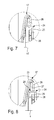
- FIGS. 4 to 8 show a second embodiment of the suspension device 11 according to the invention.
- the stopper projection 29 is disposed on the wall bracket 24.
- the stopper projection comprises a stop tab 31 which is integrally formed on the wall holder 24, and projects transversely thereof from the front.
- the stop tab 31 is formed out of the material of the wall rail.
- the stop tab 31 is located at the transition between the base portion 25 and the Ein vonsky 27 of the wall rail.
- the stop tab 31 is substantially perpendicular to the Ein vonsky 27 forward, so away from the building wall, from.
- the stop tab engages in the suspended state of the support bracket 17 there arranged abutment surface 32.
- a recess 33 is formed in the bracket portion 23 of the support bracket 17.
- the recess 33 is open at the top and is bounded by three side walls, of which a vertical side wall forms the stop surface 32, which is overlapped by the stop tab 31 of the wall rail ( FIG. 6 , Assault ü1).
- the stop surface 32 abuts against the lower edge of the stop tab 31, whereby unintentional detachment of the support bracket 17 is prevented from the wall rail.
- FIGS. 7 and 8 shows the support tab is pivoted to the intended hanging out of the wall rail relative to the wall rail.
- FIG. 7 shows a position of the support bracket 17 with respect to the wall rail, in which the maximum pivoting has not been completely covered, ie between the inside of the vertical wall on Ein vonabrisk 27 of the wall bracket and the suspension leg of the bracket portion 23 of the support bracket is still a small but pivotal play.
- the stop tab 31 still overlaps the stop surface 32 (FIG. FIG. 7 , Override ü2 ⁇ ü1) so that unhooking is prevented. This ensures that the support strap against unintentional unhooking then secured, if it is not moved purely vertically up, but obliquely above.
- FIGS. 9 to 13 show a third embodiment of the suspension device 11 of the invention.
- the third embodiment of the invention differs from the first embodiment described above also in that the stopper projection 29 on the wall bracket 24, that is arranged on the wall.
- the stopper projection 29 is not integrally connected to the wall rail, but the stopper projection 29 is formed on a separately formed from the wall rail and fixed to the wall rail additional part 34.
- the additional part 34 is formed as a short U-rail piece, which can be accurately inserted into the likewise U-shaped base portion 25 of the wall rail.
- the stop projection in turn comprises a stop tab 31, which is formed on the upper leg of the additional part 34 and in particular formed there.
- the stop tab 31 in turn engages over an abutment surface 32 formed on the support lug in an identical manner to the previously described embodiment.
- the safety device against unintentional unhooking is therefore designed in the same way as in the second embodiment. For intentional unhooking the support tab 17 is then so far pivoted as in the second embodiment described above, that the stop tab is disengaged from the stop surface 32, so that the support bracket 17 can be posted.
Landscapes
- Supports Or Holders For Household Use (AREA)
- Combinations Of Kitchen Furniture (AREA)
Abstract
Description
Die Erfindung betrifft eine Aufhängevorrichtung für Möbel, insbesondere Schrankmöbel oder dergleichen, mit wenigstens einem am Möbel befestigbaren Montageelement, an dem wenigstens eine Traglasche angeordnet ist, die in ihre Gebrauchslage in einen ebenfalls zur Aufhängevorrichtung gehörenden Wandhalter eingehängt ist, wobei Aushängesicherungsmittel vorgesehen sind, die einen an einem Grundkörper der Traglasche angeordneten Anschlagvorsprung aufweisen, der in der Gebrauchslage der Traglasche derart zum Wandhalter ausgerichtet ist, dass ein unbeabsichtigtes Aushängen aus dem Wandhalter verhindert wird, wobei die Traglasche zum beabsichtigten Aushängen in eine Freigabestellung bewegbar ist, in der der Anschlagvorsprung außer Eingriff zum Wandhalter gelangt.The invention relates to a suspension device for furniture, in particular cupboard furniture or the like, with at least one attachable to the furniture mounting member to which at least one support tab is arranged, which is mounted in its position of use in a likewise belonging to the suspension wall bracket, wherein Aushängesicherungsmittel are provided, the one have on a base body of the support tab arranged stop projection, which is aligned in the position of use of the support bracket to the wall holder, that accidental unhooking from the wall holder is prevented, wherein the support tab for intentional unhooking in a release position is movable, in which the stopper protrusion out of engagement Wandhalter arrives.
Eine derartige Aufhängevorrichtung für Möbel ist in der
Aufgabe der Erfindung ist es, eine Aufhängevorrichtung für Möbel der eingangs erwähnten Art zu schaffen, die kostengünstig herstellbar ist, bei der zuverlässig wirkende Aushängesicherungsmittel vorgesehen sind und die einfach handhabbar ist.The object of the invention is to provide a suspension device for furniture of the type mentioned above, which is inexpensive to produce, are provided in the reliable acting Aushängesicherungsmittel and is easy to handle.
Diese Aufgabe wird durch eine Aufhängevorrichtung für Möbel mit den Merkmalen des unabhängigen Anspruchs 1 gelöst. Weiterbildungen der Erfindung sind in den Unteransprüchen dargestellt.This object is achieved by a suspension device for furniture with the features of the
Die erfindungsgemäße Aufhängevorrichtung für Möbel zeichnet sich dadurch aus, dass der Anschlagvorsprung derart fest an der Traglasche angeordnet ist und die Traglasche bezüglich des Wandhalters eine derartige Schwenkfreiheit besitzt, dass die Traglasche bei unveränderbarer Relativposition zwischen dem Anschlagvorsprung und dem Grundkörper aus der Gebrauchslage in die Freigabestellung verschwenkbar ist.The suspension device for furniture according to the invention is characterized in that the stop projection is so firmly attached to the support bracket and the support bracket with respect to the wall bracket has such a pivoting freedom that the support tab in unchangeable relative position between the stopper projection and the base body from the use position in the release position is.
Es ist also nicht notwendig, beispielsweise ein Stellbolzen wie im Stand der Technik beschrieben, aktiv insbesondere mittels eines geeigneten Betätigungswerkzeugs in eine Freigabestellung zu verstellen, damit die Traglasche aus dem Wandhalter ausgehängt werden kann. Bei der erfindungsgemäßen Aufhängevorrichtung reicht eine Handhabung am Möbel und damit eine Handhabung der am Möbel befestigten Traglasche aus, um ein beabsichtigtes Aushängen zu erwirken. Zwar ist es denkbar, dass der Anschlagvorsprung ebenfalls verstellbar gelagert ist, jedoch braucht er zum Zwecke des Aushängens der Traglasche aus dem Wandhalter nicht verstellt werden.It is therefore not necessary, for example, an adjusting bolt as described in the prior art, actively to adjust in particular by means of a suitable operating tool in a release position, so that the support bracket can be posted from the wall bracket. In the suspension device according to the invention sufficient handling on the furniture and thus handling of the attached to the furniture support bracket to obtain an intentional unhooking. Although it is conceivable that the stopper projection is also mounted adjustable, but it does not need to be adjusted for the purpose of unhooking the support bracket from the wall bracket.
Bei einer Weiterbildung der Erfindung untergreift der Anschlagvorsprung in der Gebrauchslage der Traglasche den Wandhalter. Beispielsweise kann der Anschlagvorsprung die Unterkante des Wandhalters untergreifen. Es ist jedoch auch denkbar, dass am Wandhalter andere geeignete Abschnitte ausgebildet sind, die vom Anschlagvorsprung untergriffen werden können.In a further development of the invention, the stop projection engages under the wall bracket in the position of use of the support bracket. For example, the stop projection can engage under the lower edge of the wall holder. However, it is also conceivable that other suitable sections are formed on the wall holder, which can be engaged by the stop projection.
In besonders bevorzugter Weise weist der Wandhalter einen Einhängeabschnitt zum Einhängen des Grundkörpers der Traglasche auf, der zusätzlich als Schwenklager für den Grundkörper der Traglasche fungiert. Das Aushängen kann also durch eine Schwenkbewegung der Traglasche gegenüber dem Wandhalter erfolgen, bei der der Anschlagvorsprung außer Eingriff zum Wandhalter gelangt.In a particularly preferred manner, the wall holder on a Einhängeabschnitt for suspending the main body of the support tab, which also acts as a pivot bearing for the main body of the support bracket. The unhooking can thus be done by a pivoting movement of the support bracket relative to the wall bracket, in which the stopper projection is disengaged from the wall bracket.
Zweckmäßigerweise ragt der Einhängeabschnitt in der Montageposition des Wandhalters von der Gebäudewand nach vorne weg. In diesem Fall wird also zwischen der Gebäudewand und dem Einhängeabschnitt ein Spalt ausgebildet, in den ein dazu bestimmter Abschnitt der Traglasche eingehängt werden kann.Expediently, the suspension section protrudes forwardly away from the building wall in the mounting position of the wall bracket. In this case, a gap is thus formed between the building wall and the suspension section, in which a specific section of the support strap can be suspended.
Bei einer Weiterbildung der Erfindung weist der Grundkörper der Traglasche einen Basisabschnitt auf, an dem der Anschlagvorsprung ausgebildet ist. Zweckmäßigerweise besitzt die Traglasche zusätzlich zu dem Basisabschnitt noch einen Bügelabschnitt zum Einhängen in den Wandhaken. Basisabschnitt und Bügelabschnitt sind zweckmäßigerweise einstückig miteinander ausgebildet, können also bei der Herstellung der Traglasche gleich mit angeformt werden.In a further development of the invention, the main body of the support bracket on a base portion on which the stopper projection is formed. Conveniently, the support tab in addition to the base portion still has a bracket section for hanging in the wall hook. Base section and Ironing section are advantageously integrally formed with each other, so they can be formed with the same in the production of the support bracket.
In besonders bevorzugter Weise besteht die Traglasche und/oder der Wandhalter aus Metallmaterial, vorzugsweise Stahlmaterial, insbesondere Baustahl.In a particularly preferred manner, the support tab and / or the wall holder made of metal material, preferably steel material, in particular mild steel.
Bei einer Weiterbildung der Erfindung weist der Bügelabschnitt der Traglasche zwei V-förmig zueinander angeordnete Bügelschenkel auf, von denen ein Einhängeschenkel den Einhängeabschnitt des Wandhalters beim Einhängen hintergreift. Die V-förmige Ausgestaltung der beiden Bügelschenkel bildet ein Schwenkspiel gegenüber dem Wandhalter, falls die Traglasche im Wandhalter eingehängt ist. Der Bügelabschnitt mit seinen beiden Bügelschenkeln und der Einhängeabschnitt am Wandhalter können also gemeinsam ein Schwenklager bilden, das ein Verschwenken der Traglasche zum Zwecke des beabsichtigten Aushängens aus dem Wandhalter ermöglicht.In a further development of the invention, the bracket portion of the support bracket on two V-shaped mutually arranged stirrup legs, of which a suspension leg engages behind the Einhängeabschnitt of the wall bracket when hanging. The V-shaped configuration of the two stirrup legs forms a pivoting play relative to the wall holder, if the support tab is suspended in the wall holder. The bracket portion with its two stirrup legs and the Einhängeabschnitt on the wall bracket can therefore together form a pivot bearing, which allows pivoting of the support bracket for the purpose of the intended Aushängens from the wall bracket.
Zweckmäßigerweise ist der Abstand zwischen der Oberkante des Bügelabschnitts und dem Anschlagvorsprung größer als die Höhe des Wandhalters. Dadurch, dass der Anschlagvorsprung relativ weit vom Schwenkpunkt der Traglasche entfernt ist, reicht ein relativ kurzer Schwenkweg aus, damit der Anschlagvorsprung außer Eingriff zum Wandhalter gelangt.Conveniently, the distance between the upper edge of the bracket portion and the stopper projection is greater than the height of the wall bracket. Characterized in that the stopper projection is relatively far away from the pivot point of the support tab, a relatively short pivoting is sufficient so that the stopper projection is disengaged from the wall bracket.
In besonders bevorzugter Weise ist der Anschlagvorsprung einstückig mit dem Grundkörper der Traglasche verbunden, insbesondere aus dem Material des Grundkörpers herausgebildet. Es ist jedoch auch möglich, dass der Anschlagvorsprung ein am Grundkörper befestigtes Zusatzteil ist.In a particularly preferred manner, the stop projection is integrally connected to the base body of the support tab, in particular formed out of the material of the base body. However, it is also possible that the stop projection is attached to the main body attachment.
Die Erfindung umfasst ferner eine Aufhängevorrichtung mit den Merkmalen des unabhängigen Anspruchs 9.The invention further comprises a suspension device having the features of independent claim 9.
Die Aufhängevorrichtung gemäß Anspruch 9 zeichnet sich dadurch aus, dass der Anschlagvorsprung am Wandhalter angeordnet ist.The suspension device according to claim 9 is characterized in that the stopper projection is arranged on the wall holder.
Auch hier sind also Aushängesicherungsmittel vorgesehen, wobei diese einen Anschlagvorsprung am Wandhalter umfassen.In this case as well, safety catch means are provided, wherein these comprise a stop projection on the wall holder.
Bei einer Weiterbildung der Erfindung ist der Anschlagvorsprung einstückig mit dem Wandhalter verbunden. Zweckmäßigerweise ist er aus dem Material des Wandhalters herausgebildet. Er kann also bei der Herstellung des Wandhalters gleich mit angeformt werden.In a further development of the invention, the stop projection is integrally connected to the wall holder. Conveniently, it is formed out of the material of the wall holder. It can therefore be molded with the same during the production of the wall holder.
Bei einer Weiterbildung der Erfindung weist der Wandhalter einen Basisabschnitt auf, über den er mittels Befestigungsmitteln an einer Gebäudewand befestigbar ist. Ferner weist der Wandhalter einen Einhängeabschnitt zum Einhängen der Traglasche auf, wobei der Anschlagvorsprung am Einhängeabschnitt ausgebildet ist.In a development of the invention, the wall holder has a base section, by means of which it can be fastened to a building wall by means of fastening means. Further, the wall holder has a Einhängeabschnitt for suspending the support tab, wherein the stopper projection is formed on the Einhängeabschnitt.
Es ist möglich, dass der Anschlagvorsprung quer vom Einhängeabschnitt absteht und bei eingehängter Traglasche eine dort angeordnete Anschlagfläche übergreift.It is possible for the stop projection to protrude transversely from the suspension section and, when the suspension strap is suspended, engage over a stop surface arranged there.
Bei einer Weiterbildung der Erfindung ist der Anschlagvorsprung an einem separat von dem Wandhalter ausgebildeten und am Wandhalter befestigbaren oder befestigten Zusatzteil ausgebildet. Bei dieser Variante lassen sich herkömmliche Wandhalter nachrüsten. In besonders bevorzugter Weise ist das Zusatzteil am Basisabschnitt des Wandhalters befestigt, wobei vorzugsweise die Befestigung des Zusatzteils am Wandhalter über dieselben Befestigungsmittel erfolgt, die auch für die Befestigung des Wandhalters an der Gebäudewand verwendet werden.In a further development of the invention, the stop projection is formed on a separately formed from the wall bracket and fastened to the wall bracket or attached additional part. In this variant, conventional wall mount can be retrofitted. In a particularly preferred manner, the additional part is attached to the base portion of the wall holder, wherein preferably the attachment of the additional part to the wall holder takes place via the same fasteners that are also used for attaching the wall bracket to the building wall.
Die Erfindung umfasst ferner noch ein Möbel, insbesondere Schrankmöbel mit den Merkmalen des unabhängigen Anspruchs 15.The invention further comprises a piece of furniture, in particular cupboard furniture having the features of
Bevorzugte Ausführungsbeispiele der Erfindung sind in der Zeichnung dargestellt und werden im Folgenden näher erläutert. In der Zeichnung zeigen:
Figur 1- eine perspektivische Darstellung eines ersten Ausführungsbeispiels der erfindungsgemäßen Aufhängevorrichtung,
- Figur 2
- eine Seitenansicht der Aufhängevorrichtung von
Figur 1 - Figur 3
- eine Seitenansicht der Aufhängevorrichtung von
Figur 1 - Figur 4
- eine perspektivische Darstellung eines zweiten Ausführungsbeispiels der erfindungsgemäßen Aufhängevorrichtung,
Figur 5- eine Seitenansicht der Aufhängevorrichtung von
Figur 4 bei eingehängter Traglasche mit dem Anschlagvorsprung in Sicherungsstellung, - Figur 6
- eine vergrößerte Darstellung der Einzelheit X aus
Figur 5 - Figur 7
- eine Variante der vergrößerten Darstellung von
Figur 6 beim Aushängen der Traglasche, wobei der Anschlagvorsprung noch in Eingriff mit der Traglasche steht, - Figur 8
- eine Variante der Einzelheit X von
Figur 6 , wobei der Anschlagvorsprung außer Eingriff zur Traglasche ist, - Figur 9
- eine perspektivische Darstellung eines dritten Ausführungsbeispiels der erfindungsgemäßen Aufhängevorrichtung,
- Figur 10
- eine Seitenansicht der Aufhängevorrichtung von
Figur 9 mit eingehängter Traglasche mit dem Anschlagvorsprung in Sicherungsstellung, Figur 11- eine vergrößerte Darstellung der Einzelheit Y aus
Figur 10 , Figur 12- eine Variante der Einzelheit Y aus
Figur 11 beim Aushängen der Traglasche, wobei der Anschlagvorsprung noch in Eingriff mit der Traglasche ist und Figur 13- eine weitere Variante der Einzelheit Y aus
Figur 11 , wobei der Anschlagvorsprung außer Eingriff mit der Traglasche steht.
- FIG. 1
- a perspective view of a first embodiment of the suspension device according to the invention,
- FIG. 2
- a side view of the suspension of
FIG. 1 with hinged support bracket with the stop projection in the securing position, - FIG. 3
- a side view of the suspension of
FIG. 1 when hanging the support tab with the stop projection out of engagement with the wall holder, - FIG. 4
- a perspective view of a second embodiment of the suspension device according to the invention,
- FIG. 5
- a side view of the suspension of
FIG. 4 with hinged support bracket with the stop projection in the securing position, - FIG. 6
- an enlarged view of the detail X from
FIG. 5 . - FIG. 7
- a variant of the enlarged view of
FIG. 6 when hanging the support tab, wherein the stopper projection is still in engagement with the support tab, - FIG. 8
- a variant of the detail X of
FIG. 6 wherein the stopper projection is disengaged from the support tab, - FIG. 9
- a perspective view of a third embodiment of the suspension device according to the invention,
- FIG. 10
- a side view of the suspension of
FIG. 9 with hinged support bracket with the stop projection in the securing position, - FIG. 11
- an enlarged view of the detail Y from
FIG. 10 . - FIG. 12
- a variant of the detail Y from
FIG. 11 when unhooking the support tab, wherein the stopper projection is still in engagement with the support tab and - FIG. 13
- another variant of the detail Y from
FIG. 11 , wherein the stopper projection is disengaged from the support tab.
Die
Die Aufhängevorrichtung 11 weist ein plattenartiges Montageelement 12 auf, das zweckmäßigerweise aus Baustahl besteht und die über Befestigungslöcher 13 und mit diesen zusammenwirkenden Befestigungsmitteln, beispielsweise Befestigungsschrauben, an der Außenseite der Schrankrückwand befestigt wird.The
Hierzu besitzt das Montageelement 12 eine plattenartige Basispartie 14, die in Anlage zur Schrankrückwand gebracht wird und dort über die erwähnten Befestigungslöcher 13 an dieser befestigt wird. Wie insbesondere in
Wie insbesondere in den
Der Grundkörper 18 der Traglasche 17 besteht im Wesentlichen aus zwei Komponenten, nämlich einem Basisabschnitt 22, an dem der Führungsschlitz 20 ausgebildet ist und einen Bügelabschnitt 23 zum Einhängen in einen ebenfalls zur Aufhängevorrichtung 11 gehörenden Wandhalter 24. Der Bügelabschnitt 23 ist in Form eines Einhängebügels ausgestaltet und besitzt zwei V-förmig zueinander angeordnete Bügelschenkel.The
Der Wandhalter 24 ist beispielhaft in Form einer Wandschiene dargestellt. Zweckmäßigerweise besteht die Wandschiene ebenfalls aus Baustahl. Die Wandschiene weist einen Basisabschnitt 25 auf, der über mehrere Montagelöcher 26 verfügt, über die sie an einer Gebäudewand befestigt werden kann. Die Wandschiene verfügt ferner über einen Einhängeabschnitt 27, der einstückig mit dem Basisabschnitt 25 verbunden ist und im montierten Zustand der Wandschiene vom Basisabschnitt nach vorne wegragt. Somit ist im montierten Zustand der Wandschiene zwischen der Gebäudewand und dem Einhängeabschnitt 27 ein Zwischenraum ausgebildet, in dem ein als Einhängeschenkel 28 ausgebildeter Bügelschenkel des Bügelabschnitts 23 der Traglasche 17 aufgenommen ist, der gleichzeitig den Einhängeabschnitt 28 der Wandschiene hintergreift. Die Lastübertragung erfolgt daher vom Schrankmöbel im Wesentlichen über die Montagezapfen 16 auf das Montageelement 12 und von dort über die Traglasche 17 und den Bügelabschnitt 23 auf die Wandschiene.The
Als wesentliches Element der Aufhängevorrichtung 11 sind Aushängesicherungsmittel vorgesehen, die einen Anschlagvorsprung 29 aufweisen, der in der Gebrauchslage der Traglasche 17 derart zur Wandschiene ausgerichtet ist, dass ein unbeabsichtigtes Aushängen aus der Wandschiene verhindert wird. Zum beabsichtigten Aushängen ist die Traglasche 17 in eine Freigabestellung bewegbar, in der der Anschlagvorsprung 29 außer Eingriff zur Wandschiene gelangt.As an essential element of the
Gemäß dem ersten Ausführungsbeispiel der Erfindung ist der Anschlagvorsprung 29 am Grundkörper 18 der Traglasche 17 angeordnet. Wie insbesondere in
Wie insbesondere in
Soll die Traglasche 17 und mit dieser das aufgehängte Schrankmöbel beabsichtigt aus der Wandschiene ausgehängt werden, ist dies auch ohne Weiteres in einfacher Weise durchführbar. Wie insbesondere die Zusammenschau der
Ein Vorteil der Ausgestaltung des Anschlagvorsprungs 29 ist, dass dieser derart fest an der Traglasche 17 angeordnet ist, und die Traglasche bezüglich der Wandschiene eine derartige Schwenkfreiheit besitzt, dass die Traglasche 17 bei unveränderbarer Relativposition zwischen dem Anschlagvorsprung 29 und dem Grundkörper aus der Gebrauchslage in die Freigabestellung verschwenkbar ist. Es ist hier also nicht notwendig, den Anschlagvorsprung aktiv in eine Freigabestellung zu verstellen, damit ausgehängt werden kann. Daher sind auch keine Durchbrüche durch die Schrankrückwand notwendig, um den Anschlagvorsprung verstellen zu können. Die Erfindung kommt daher ohne solche Durchbrüche aus, wobei dennoch ein einfaches Aushängen möglich ist, falls dieses beabsichtigt wird.An advantage of the design of the
Die
Wie insbesondere in
Bei einer Bewegung der Traglasche 17 bzw. des damit verbundenen Schrankmöbels nach oben, schlägt die Anschlagfläche 32 an die Unterkante der Anschlaglasche 31 an, wodurch ein unbeabsichtigtes Aushängen der Traglasche 17 aus der Wandschiene verhindert wird.In a movement of the
Wie insbesondere die Zusammenschau der
Soll die Traglasche 17 jedoch tatsächlich aus der Wandschiene ausgehängt werden, so wird diese maximal gegenüber der Wandschiene verschenkt, bis der Einhängeschenkel an die Innenseite der Vertikalwand des Einhängeabschnitts 27 anschlägt. Erst dann gelangt die Anschlaglasche außer Eingriff zur Anschlagfläche 32 (
Die
Wie insbesondere in
Die Anschlaglasche 31 übergreift wiederum eine an der Traglasche in identischer Weise zum zuvor beschriebenen Ausführungsbeispiel ausgebildete Anschlagfläche 32. Die Sicherung gegen unbeabsichtigtes Aushängen ist daher in gleicher Weise wie beim zweiten Ausführungsbeispiel ausgeführt. Zum beabsichtigten Aushängen wird die Traglasche 17 dann wie beim zuvor beschriebenen zweiten Ausführungsbeispiel so weit verschwenkt, dass die Anschlaglasche außer Eingriff zur Anschlagfläche 32 kommt, so dass die Traglasche 17 ausgehängt werden kann.The
Claims (15)
Applications Claiming Priority (1)
| Application Number | Priority Date | Filing Date | Title |
|---|---|---|---|
| DE201220012377 DE202012012377U1 (en) | 2012-12-20 | 2012-12-20 | Hanging device for furniture |
Publications (2)
| Publication Number | Publication Date |
|---|---|
| EP2745739A1 true EP2745739A1 (en) | 2014-06-25 |
| EP2745739B1 EP2745739B1 (en) | 2018-07-11 |
Family
ID=49726422
Family Applications (1)
| Application Number | Title | Priority Date | Filing Date |
|---|---|---|---|
| EP13005581.7A Active EP2745739B1 (en) | 2012-12-20 | 2013-11-30 | Suspension fitting for a wall mounted cabinet |
Country Status (3)
| Country | Link |
|---|---|
| EP (1) | EP2745739B1 (en) |
| DE (1) | DE202012012377U1 (en) |
| ES (1) | ES2687237T3 (en) |
Families Citing this family (7)
| Publication number | Priority date | Publication date | Assignee | Title |
|---|---|---|---|---|
| DE102016101624A1 (en) | 2015-07-03 | 2017-01-05 | Hettich-Heinze Gmbh & Co. Kg | Hanging device for furniture and method for unhooking a suspension device |
| DE202015103519U1 (en) | 2015-07-03 | 2016-10-07 | Hettich-Heinze Gmbh & Co. Kg | Hanging device for a furniture |
| EP3111802B1 (en) | 2015-07-03 | 2019-01-09 | Hettich-Heinze GmbH & Co. KG | Suspension device for a piece of furniture and method for disengaging a suspension device |
| DE102017108118A1 (en) | 2017-04-13 | 2018-10-18 | Hettich-Heinze Gmbh & Co. Kg | Suspension device for hanging a piece of furniture on a wall and use of such a suspension device |
| DE102017108117A1 (en) | 2017-04-13 | 2018-10-18 | Hettich-Heinze Gmbh & Co. Kg | Suspension device for hanging a piece of furniture on a wall and use of such a suspension device |
| DE202017002159U1 (en) | 2017-04-25 | 2018-07-30 | Hetal-Werke Franz Hettich Gmbh & Co. Kg | Hanging device for furniture |
| IT201700110599A1 (en) * | 2017-10-03 | 2019-04-03 | Leonardo Srl | REGGIPENSILE GROUP HIDDEN RESISTANT TO TEAR AND WITH PRECISE DEPTH ADJUSTMENT |
Citations (6)
| Publication number | Priority date | Publication date | Assignee | Title |
|---|---|---|---|---|
| EP0307884A1 (en) * | 1987-09-16 | 1989-03-22 | Moulinex S.A. | Suspension device for attaching an electrical kitchen appliance, such as an oven, to a wall |
| US5050832A (en) * | 1990-05-18 | 1991-09-24 | Lee/Rowan Company | Modular storage unit mounting system |
| GB2269981A (en) * | 1992-08-25 | 1994-03-02 | Titus Int Ltd | "Mounting device" |
| US20080067139A1 (en) * | 2006-09-20 | 2008-03-20 | Rubbermaid Incorporated | Over the Door Storage Assembly |
| DE202009007795U1 (en) * | 2009-06-04 | 2009-08-20 | Robbes & Lammers Gmbh & Co. Kg | Wall mounting amplifier for furniture cages |
| DE202011001589U1 (en) | 2011-01-15 | 2011-03-24 | Hetal-Werke Franz Hettich Gmbh & Co. Kg | Hanging device for furniture |
-
2012
- 2012-12-20 DE DE201220012377 patent/DE202012012377U1/en not_active Expired - Lifetime
-
2013
- 2013-11-30 ES ES13005581.7T patent/ES2687237T3/en active Active
- 2013-11-30 EP EP13005581.7A patent/EP2745739B1/en active Active
Patent Citations (6)
| Publication number | Priority date | Publication date | Assignee | Title |
|---|---|---|---|---|
| EP0307884A1 (en) * | 1987-09-16 | 1989-03-22 | Moulinex S.A. | Suspension device for attaching an electrical kitchen appliance, such as an oven, to a wall |
| US5050832A (en) * | 1990-05-18 | 1991-09-24 | Lee/Rowan Company | Modular storage unit mounting system |
| GB2269981A (en) * | 1992-08-25 | 1994-03-02 | Titus Int Ltd | "Mounting device" |
| US20080067139A1 (en) * | 2006-09-20 | 2008-03-20 | Rubbermaid Incorporated | Over the Door Storage Assembly |
| DE202009007795U1 (en) * | 2009-06-04 | 2009-08-20 | Robbes & Lammers Gmbh & Co. Kg | Wall mounting amplifier for furniture cages |
| DE202011001589U1 (en) | 2011-01-15 | 2011-03-24 | Hetal-Werke Franz Hettich Gmbh & Co. Kg | Hanging device for furniture |
Also Published As
| Publication number | Publication date |
|---|---|
| DE202012012377U1 (en) | 2014-03-21 |
| ES2687237T3 (en) | 2018-10-24 |
| ES2687237T8 (en) | 2018-12-14 |
| EP2745739B1 (en) | 2018-07-11 |
Similar Documents
| Publication | Publication Date | Title |
|---|---|---|
| EP2745739B1 (en) | Suspension fitting for a wall mounted cabinet | |
| EP1784578B1 (en) | U-shaped clamp | |
| AT511683B1 (en) | DRAWER | |
| EP3556976A1 (en) | Device for moving a piece of furniture on a body of a piece of furniture | |
| DE202014106123U1 (en) | Front coupling device for hidden pull-out rails | |
| EP3111801B1 (en) | Suspension device for furniture | |
| DE7804845U1 (en) | HINGE | |
| DE112016001573T5 (en) | IMPROVED HINGE FOR A FURNITURE DOOR | |
| DE102011115548B4 (en) | Fastening device for fastening an installation device to a mounting rail | |
| AT509539A2 (en) | ATTACHING DEVICE FOR A FURNITURE AND FURNITURE | |
| EP3111802B1 (en) | Suspension device for a piece of furniture and method for disengaging a suspension device | |
| DE202011001589U1 (en) | Hanging device for furniture | |
| DE3024746C2 (en) | Opening device for tilt-swivel sash of windows, doors or the like. | |
| AT519660B1 (en) | joint assembly | |
| EP0786631B1 (en) | Device for mounting objects such as radiators against a wall | |
| AT517072B1 (en) | connecting fitting | |
| DE202018006086U1 (en) | Hanging device for furniture | |
| EP2778325B1 (en) | Locking device | |
| DE102016101624A1 (en) | Hanging device for furniture and method for unhooking a suspension device | |
| DE102015219124A1 (en) | Attachment for a vehicle | |
| EP2295873B1 (en) | Device | |
| DE102008048933A1 (en) | Device and method for mounting a furniture drawer slide for pull-out elements | |
| EP1598489B1 (en) | Fixing device for a built-in element, insertable in an opening of a support plate | |
| EP2730196B1 (en) | Device for connecting a front of a movable part of a piece of furniture to its side element | |
| DE29902768U1 (en) | Mounting plate for furniture hinges |
Legal Events
| Date | Code | Title | Description |
|---|---|---|---|
| PUAI | Public reference made under article 153(3) epc to a published international application that has entered the european phase |
Free format text: ORIGINAL CODE: 0009012 |
|
| 17P | Request for examination filed |
Effective date: 20131130 |
|
| AK | Designated contracting states |
Kind code of ref document: A1 Designated state(s): AL AT BE BG CH CY CZ DE DK EE ES FI FR GB GR HR HU IE IS IT LI LT LU LV MC MK MT NL NO PL PT RO RS SE SI SK SM TR |
|
| AX | Request for extension of the european patent |
Extension state: BA ME |
|
| R17P | Request for examination filed (corrected) |
Effective date: 20141222 |
|
| RBV | Designated contracting states (corrected) |
Designated state(s): AL AT BE BG CH CY CZ DE DK EE ES FI FR GB GR HR HU IE IS IT LI LT LU LV MC MK MT NL NO PL PT RO RS SE SI SK SM TR |
|
| 17Q | First examination report despatched |
Effective date: 20160801 |
|
| GRAP | Despatch of communication of intention to grant a patent |
Free format text: ORIGINAL CODE: EPIDOSNIGR1 |
|
| INTG | Intention to grant announced |
Effective date: 20180216 |
|
| GRAS | Grant fee paid |
Free format text: ORIGINAL CODE: EPIDOSNIGR3 |
|
| GRAA | (expected) grant |
Free format text: ORIGINAL CODE: 0009210 |
|
| AK | Designated contracting states |
Kind code of ref document: B1 Designated state(s): AL AT BE BG CH CY CZ DE DK EE ES FI FR GB GR HR HU IE IS IT LI LT LU LV MC MK MT NL NO PL PT RO RS SE SI SK SM TR |
|
| REG | Reference to a national code |
Ref country code: GB Ref legal event code: FG4D Free format text: NOT ENGLISH |
|
| REG | Reference to a national code |
Ref country code: CH Ref legal event code: EP |
|
| REG | Reference to a national code |
Ref country code: AT Ref legal event code: REF Ref document number: 1016015 Country of ref document: AT Kind code of ref document: T Effective date: 20180715 |
|
| REG | Reference to a national code |
Ref country code: IE Ref legal event code: FG4D Free format text: LANGUAGE OF EP DOCUMENT: GERMAN |
|
| REG | Reference to a national code |
Ref country code: DE Ref legal event code: R096 Ref document number: 502013010566 Country of ref document: DE |
|
| REG | Reference to a national code |
Ref country code: ES Ref legal event code: FG2A Ref document number: 2687237 Country of ref document: ES Kind code of ref document: T3 Effective date: 20181024 |
|
| REG | Reference to a national code |
Ref country code: NL Ref legal event code: MP Effective date: 20180711 |
|
| REG | Reference to a national code |
Ref country code: LT Ref legal event code: MG4D |
|
| PG25 | Lapsed in a contracting state [announced via postgrant information from national office to epo] |
Ref country code: NL Free format text: LAPSE BECAUSE OF FAILURE TO SUBMIT A TRANSLATION OF THE DESCRIPTION OR TO PAY THE FEE WITHIN THE PRESCRIBED TIME-LIMIT Effective date: 20180711 |
|
| PG25 | Lapsed in a contracting state [announced via postgrant information from national office to epo] |
Ref country code: PL Free format text: LAPSE BECAUSE OF FAILURE TO SUBMIT A TRANSLATION OF THE DESCRIPTION OR TO PAY THE FEE WITHIN THE PRESCRIBED TIME-LIMIT Effective date: 20180711 Ref country code: LT Free format text: LAPSE BECAUSE OF FAILURE TO SUBMIT A TRANSLATION OF THE DESCRIPTION OR TO PAY THE FEE WITHIN THE PRESCRIBED TIME-LIMIT Effective date: 20180711 Ref country code: BG Free format text: LAPSE BECAUSE OF FAILURE TO SUBMIT A TRANSLATION OF THE DESCRIPTION OR TO PAY THE FEE WITHIN THE PRESCRIBED TIME-LIMIT Effective date: 20181011 Ref country code: SE Free format text: LAPSE BECAUSE OF FAILURE TO SUBMIT A TRANSLATION OF THE DESCRIPTION OR TO PAY THE FEE WITHIN THE PRESCRIBED TIME-LIMIT Effective date: 20180711 Ref country code: NO Free format text: LAPSE BECAUSE OF FAILURE TO SUBMIT A TRANSLATION OF THE DESCRIPTION OR TO PAY THE FEE WITHIN THE PRESCRIBED TIME-LIMIT Effective date: 20181011 Ref country code: RS Free format text: LAPSE BECAUSE OF FAILURE TO SUBMIT A TRANSLATION OF THE DESCRIPTION OR TO PAY THE FEE WITHIN THE PRESCRIBED TIME-LIMIT Effective date: 20180711 Ref country code: IS Free format text: LAPSE BECAUSE OF FAILURE TO SUBMIT A TRANSLATION OF THE DESCRIPTION OR TO PAY THE FEE WITHIN THE PRESCRIBED TIME-LIMIT Effective date: 20181111 Ref country code: FI Free format text: LAPSE BECAUSE OF FAILURE TO SUBMIT A TRANSLATION OF THE DESCRIPTION OR TO PAY THE FEE WITHIN THE PRESCRIBED TIME-LIMIT Effective date: 20180711 Ref country code: GR Free format text: LAPSE BECAUSE OF FAILURE TO SUBMIT A TRANSLATION OF THE DESCRIPTION OR TO PAY THE FEE WITHIN THE PRESCRIBED TIME-LIMIT Effective date: 20181012 |
|
| PG25 | Lapsed in a contracting state [announced via postgrant information from national office to epo] |
Ref country code: LV Free format text: LAPSE BECAUSE OF FAILURE TO SUBMIT A TRANSLATION OF THE DESCRIPTION OR TO PAY THE FEE WITHIN THE PRESCRIBED TIME-LIMIT Effective date: 20180711 Ref country code: HR Free format text: LAPSE BECAUSE OF FAILURE TO SUBMIT A TRANSLATION OF THE DESCRIPTION OR TO PAY THE FEE WITHIN THE PRESCRIBED TIME-LIMIT Effective date: 20180711 Ref country code: AL Free format text: LAPSE BECAUSE OF FAILURE TO SUBMIT A TRANSLATION OF THE DESCRIPTION OR TO PAY THE FEE WITHIN THE PRESCRIBED TIME-LIMIT Effective date: 20180711 |
|
| REG | Reference to a national code |
Ref country code: DE Ref legal event code: R097 Ref document number: 502013010566 Country of ref document: DE |
|
| PG25 | Lapsed in a contracting state [announced via postgrant information from national office to epo] |
Ref country code: EE Free format text: LAPSE BECAUSE OF FAILURE TO SUBMIT A TRANSLATION OF THE DESCRIPTION OR TO PAY THE FEE WITHIN THE PRESCRIBED TIME-LIMIT Effective date: 20180711 Ref country code: RO Free format text: LAPSE BECAUSE OF FAILURE TO SUBMIT A TRANSLATION OF THE DESCRIPTION OR TO PAY THE FEE WITHIN THE PRESCRIBED TIME-LIMIT Effective date: 20180711 Ref country code: CZ Free format text: LAPSE BECAUSE OF FAILURE TO SUBMIT A TRANSLATION OF THE DESCRIPTION OR TO PAY THE FEE WITHIN THE PRESCRIBED TIME-LIMIT Effective date: 20180711 |
|
| PLBE | No opposition filed within time limit |
Free format text: ORIGINAL CODE: 0009261 |
|
| STAA | Information on the status of an ep patent application or granted ep patent |
Free format text: STATUS: NO OPPOSITION FILED WITHIN TIME LIMIT |
|
| PG25 | Lapsed in a contracting state [announced via postgrant information from national office to epo] |
Ref country code: SK Free format text: LAPSE BECAUSE OF FAILURE TO SUBMIT A TRANSLATION OF THE DESCRIPTION OR TO PAY THE FEE WITHIN THE PRESCRIBED TIME-LIMIT Effective date: 20180711 Ref country code: SM Free format text: LAPSE BECAUSE OF FAILURE TO SUBMIT A TRANSLATION OF THE DESCRIPTION OR TO PAY THE FEE WITHIN THE PRESCRIBED TIME-LIMIT Effective date: 20180711 Ref country code: DK Free format text: LAPSE BECAUSE OF FAILURE TO SUBMIT A TRANSLATION OF THE DESCRIPTION OR TO PAY THE FEE WITHIN THE PRESCRIBED TIME-LIMIT Effective date: 20180711 |
|
| 26N | No opposition filed |
Effective date: 20190412 |
|
| REG | Reference to a national code |
Ref country code: CH Ref legal event code: PL |
|
| PG25 | Lapsed in a contracting state [announced via postgrant information from national office to epo] |
Ref country code: MC Free format text: LAPSE BECAUSE OF FAILURE TO SUBMIT A TRANSLATION OF THE DESCRIPTION OR TO PAY THE FEE WITHIN THE PRESCRIBED TIME-LIMIT Effective date: 20180711 Ref country code: LU Free format text: LAPSE BECAUSE OF NON-PAYMENT OF DUE FEES Effective date: 20181130 |
|
| REG | Reference to a national code |
Ref country code: BE Ref legal event code: MM Effective date: 20181130 |
|
| REG | Reference to a national code |
Ref country code: IE Ref legal event code: MM4A |
|
| PG25 | Lapsed in a contracting state [announced via postgrant information from national office to epo] |
Ref country code: SI Free format text: LAPSE BECAUSE OF FAILURE TO SUBMIT A TRANSLATION OF THE DESCRIPTION OR TO PAY THE FEE WITHIN THE PRESCRIBED TIME-LIMIT Effective date: 20180711 Ref country code: CH Free format text: LAPSE BECAUSE OF NON-PAYMENT OF DUE FEES Effective date: 20181130 Ref country code: LI Free format text: LAPSE BECAUSE OF NON-PAYMENT OF DUE FEES Effective date: 20181130 |
|
| PG25 | Lapsed in a contracting state [announced via postgrant information from national office to epo] |
Ref country code: IE Free format text: LAPSE BECAUSE OF NON-PAYMENT OF DUE FEES Effective date: 20181130 |
|
| PG25 | Lapsed in a contracting state [announced via postgrant information from national office to epo] |
Ref country code: BE Free format text: LAPSE BECAUSE OF NON-PAYMENT OF DUE FEES Effective date: 20181130 |
|
| PG25 | Lapsed in a contracting state [announced via postgrant information from national office to epo] |
Ref country code: MT Free format text: LAPSE BECAUSE OF FAILURE TO SUBMIT A TRANSLATION OF THE DESCRIPTION OR TO PAY THE FEE WITHIN THE PRESCRIBED TIME-LIMIT Effective date: 20180711 |
|
| PG25 | Lapsed in a contracting state [announced via postgrant information from national office to epo] |
Ref country code: TR Free format text: LAPSE BECAUSE OF FAILURE TO SUBMIT A TRANSLATION OF THE DESCRIPTION OR TO PAY THE FEE WITHIN THE PRESCRIBED TIME-LIMIT Effective date: 20180711 |
|
| PG25 | Lapsed in a contracting state [announced via postgrant information from national office to epo] |
Ref country code: PT Free format text: LAPSE BECAUSE OF FAILURE TO SUBMIT A TRANSLATION OF THE DESCRIPTION OR TO PAY THE FEE WITHIN THE PRESCRIBED TIME-LIMIT Effective date: 20180711 |
|
| PG25 | Lapsed in a contracting state [announced via postgrant information from national office to epo] |
Ref country code: MK Free format text: LAPSE BECAUSE OF NON-PAYMENT OF DUE FEES Effective date: 20180711 Ref country code: CY Free format text: LAPSE BECAUSE OF FAILURE TO SUBMIT A TRANSLATION OF THE DESCRIPTION OR TO PAY THE FEE WITHIN THE PRESCRIBED TIME-LIMIT Effective date: 20180711 Ref country code: HU Free format text: LAPSE BECAUSE OF FAILURE TO SUBMIT A TRANSLATION OF THE DESCRIPTION OR TO PAY THE FEE WITHIN THE PRESCRIBED TIME-LIMIT; INVALID AB INITIO Effective date: 20131130 |
|
| P01 | Opt-out of the competence of the unified patent court (upc) registered |
Effective date: 20230528 |
|
| PGFP | Annual fee paid to national office [announced via postgrant information from national office to epo] |
Ref country code: GB Payment date: 20231123 Year of fee payment: 11 |
|
| PGFP | Annual fee paid to national office [announced via postgrant information from national office to epo] |
Ref country code: ES Payment date: 20231215 Year of fee payment: 11 |
|
| PGFP | Annual fee paid to national office [announced via postgrant information from national office to epo] |
Ref country code: IT Payment date: 20231130 Year of fee payment: 11 Ref country code: FR Payment date: 20231123 Year of fee payment: 11 Ref country code: DE Payment date: 20231011 Year of fee payment: 11 Ref country code: AT Payment date: 20231117 Year of fee payment: 11 |