EP2745104B1 - Pipe containing a metal casing with a plastics material inlay for use in low and high pressure applications, in particular as an hplc column - Google Patents
Pipe containing a metal casing with a plastics material inlay for use in low and high pressure applications, in particular as an hplc column Download PDFInfo
- Publication number
- EP2745104B1 EP2745104B1 EP12762041.7A EP12762041A EP2745104B1 EP 2745104 B1 EP2745104 B1 EP 2745104B1 EP 12762041 A EP12762041 A EP 12762041A EP 2745104 B1 EP2745104 B1 EP 2745104B1
- Authority
- EP
- European Patent Office
- Prior art keywords
- pipe
- inlay
- plastics material
- connection
- metal
- Prior art date
- Legal status (The legal status is an assumption and is not a legal conclusion. Google has not performed a legal analysis and makes no representation as to the accuracy of the status listed.)
- Active
Links
Images






Classifications
-
- F—MECHANICAL ENGINEERING; LIGHTING; HEATING; WEAPONS; BLASTING
- F16—ENGINEERING ELEMENTS AND UNITS; GENERAL MEASURES FOR PRODUCING AND MAINTAINING EFFECTIVE FUNCTIONING OF MACHINES OR INSTALLATIONS; THERMAL INSULATION IN GENERAL
- F16L—PIPES; JOINTS OR FITTINGS FOR PIPES; SUPPORTS FOR PIPES, CABLES OR PROTECTIVE TUBING; MEANS FOR THERMAL INSULATION IN GENERAL
- F16L9/00—Rigid pipes
- F16L9/14—Compound tubes, i.e. made of materials not wholly covered by any one of the preceding groups
- F16L9/147—Compound tubes, i.e. made of materials not wholly covered by any one of the preceding groups comprising only layers of metal and plastics with or without reinforcement
-
- F—MECHANICAL ENGINEERING; LIGHTING; HEATING; WEAPONS; BLASTING
- F16—ENGINEERING ELEMENTS AND UNITS; GENERAL MEASURES FOR PRODUCING AND MAINTAINING EFFECTIVE FUNCTIONING OF MACHINES OR INSTALLATIONS; THERMAL INSULATION IN GENERAL
- F16L—PIPES; JOINTS OR FITTINGS FOR PIPES; SUPPORTS FOR PIPES, CABLES OR PROTECTIVE TUBING; MEANS FOR THERMAL INSULATION IN GENERAL
- F16L15/00—Screw-threaded joints; Forms of screw-threads for such joints
- F16L15/006—Screw-threaded joints; Forms of screw-threads for such joints with straight threads
- F16L15/008—Screw-threaded joints; Forms of screw-threads for such joints with straight threads with sealing rings
-
- F—MECHANICAL ENGINEERING; LIGHTING; HEATING; WEAPONS; BLASTING
- F16—ENGINEERING ELEMENTS AND UNITS; GENERAL MEASURES FOR PRODUCING AND MAINTAINING EFFECTIVE FUNCTIONING OF MACHINES OR INSTALLATIONS; THERMAL INSULATION IN GENERAL
- F16L—PIPES; JOINTS OR FITTINGS FOR PIPES; SUPPORTS FOR PIPES, CABLES OR PROTECTIVE TUBING; MEANS FOR THERMAL INSULATION IN GENERAL
- F16L19/00—Joints in which sealing surfaces are pressed together by means of a member, e.g. a swivel nut, screwed on, or into, one of the joint parts
-
- G—PHYSICS
- G01—MEASURING; TESTING
- G01N—INVESTIGATING OR ANALYSING MATERIALS BY DETERMINING THEIR CHEMICAL OR PHYSICAL PROPERTIES
- G01N30/00—Investigating or analysing materials by separation into components using adsorption, absorption or similar phenomena or using ion-exchange, e.g. chromatography or field flow fractionation
- G01N30/02—Column chromatography
- G01N30/60—Construction of the column
-
- G—PHYSICS
- G01—MEASURING; TESTING
- G01N—INVESTIGATING OR ANALYSING MATERIALS BY DETERMINING THEIR CHEMICAL OR PHYSICAL PROPERTIES
- G01N30/00—Investigating or analysing materials by separation into components using adsorption, absorption or similar phenomena or using ion-exchange, e.g. chromatography or field flow fractionation
- G01N30/02—Column chromatography
- G01N30/60—Construction of the column
- G01N30/6004—Construction of the column end pieces
-
- G—PHYSICS
- G01—MEASURING; TESTING
- G01N—INVESTIGATING OR ANALYSING MATERIALS BY DETERMINING THEIR CHEMICAL OR PHYSICAL PROPERTIES
- G01N30/00—Investigating or analysing materials by separation into components using adsorption, absorption or similar phenomena or using ion-exchange, e.g. chromatography or field flow fractionation
- G01N30/02—Column chromatography
- G01N30/60—Construction of the column
- G01N30/6004—Construction of the column end pieces
- G01N30/6026—Fluid seals
-
- G—PHYSICS
- G01—MEASURING; TESTING
- G01N—INVESTIGATING OR ANALYSING MATERIALS BY DETERMINING THEIR CHEMICAL OR PHYSICAL PROPERTIES
- G01N30/00—Investigating or analysing materials by separation into components using adsorption, absorption or similar phenomena or using ion-exchange, e.g. chromatography or field flow fractionation
- G01N30/02—Column chromatography
- G01N30/60—Construction of the column
- G01N30/6034—Construction of the column joining multiple columns
- G01N30/6039—Construction of the column joining multiple columns in series
-
- G—PHYSICS
- G01—MEASURING; TESTING
- G01N—INVESTIGATING OR ANALYSING MATERIALS BY DETERMINING THEIR CHEMICAL OR PHYSICAL PROPERTIES
- G01N30/00—Investigating or analysing materials by separation into components using adsorption, absorption or similar phenomena or using ion-exchange, e.g. chromatography or field flow fractionation
- G01N30/02—Column chromatography
- G01N30/60—Construction of the column
- G01N30/6052—Construction of the column body
-
- G—PHYSICS
- G01—MEASURING; TESTING
- G01N—INVESTIGATING OR ANALYSING MATERIALS BY DETERMINING THEIR CHEMICAL OR PHYSICAL PROPERTIES
- G01N30/00—Investigating or analysing materials by separation into components using adsorption, absorption or similar phenomena or using ion-exchange, e.g. chromatography or field flow fractionation
- G01N30/02—Column chromatography
- G01N30/60—Construction of the column
- G01N30/6052—Construction of the column body
- G01N30/6073—Construction of the column body in open tubular form
Definitions
- the invention relates to a pipe, in particular configured as a chromatography column, for example a high performance liquid chromatography column, which has a metal casing with an inlay. Furthermore, the invention relates to a connection element for connecting a pipe of this type to a feed or discharge line.
- the invention also relates to a connection system or low and high pressure system, in particular configured as a chromatography system, especially, for example, a high pressure liquid chromatography system, comprising at least one pipe of this type and optionally a connection element of this type.
- the invention furthermore relates to a connection for a capillary system, in particular an HPLC system, containing a plastics material pressed body with a through-opening.
- High performance liquid chromatography is an established method for the chemical analysis and separation of substance mixtures.
- the method belongs to the standard equipment of a laboratory in research and industry. In particular, this method tends to be used for in-vitro diagnostics.
- the basic principle is based on the different adherence energy of substances to be separated on a known substrate.
- a substance mixture is brought into solution in a so-called mobile phase and the solution is then pressed at high pressure through a column of porous particles (stationary phase).
- the constituents of the substance mixture leave the separation column one after the other.
- the published application WO 2011/076244 A1 relates to an assembly element for a fluidics device, in particular for applications in devices for high performance liquid chromatography.
- An assembly element of a fluid coupling for coupling a pipeline to a fluidics device is disclosed.
- the assembly element contains a pipeline with an inlay, the inlay being located in a cavity of a front side of the pipeline and projecting slightly out of the line.
- the inlay is used for sealing during coupling to a chromatography device.
- the pipeline depending on the application, may have a plastics material (for example PEEK) on the inside.
- PEEK plastics material
- the drawback here is, in particular, that the connection takes place upon coupling over said inlay so that not only one joint is produced but simultaneously two joints between the pipeline and its coupling partner. Each additional connection point harbours the danger of contamination and carry-over of impurities.
- the effective connection face of the insert and innermost pipeline layer is optionally very small, which additionally reduces the reliability of the coup
- the published application EP 2 315 022 A1 shows a chromatography column with a frit ring, frit holder and end connection.
- the sealing of this system extends over a plurality of joint connections between the pipe and frit ring, frit ring and frit holder as well as frit holder and end connection.
- the numerous connection points (joint points) being produced during the coupling are problematical with regard to a carry-over of impurities and contamination.
- a biocompatible liquid chromatography column is described in the patent US 5 736 036 .
- the inner pipe of the column is integral and can therefore not be pulled through the outer pipe or separated. An axial slipping of the inner pipe relative to the outer pipe is thus ruled out.
- restrictions are imposed by this structure.
- the inner pipe is introduced by a casting method. During casting, a material-uniting connection is formed between the outer and inner pipe.
- the drawback in the casting method are the increased manufacturing costs, which in particular also arise in that with the desired thickness variation of the inner pipe, the latter cannot easily be exchanged, but the column in each case has to be manufactured in various configurations.
- the outlay to produce various combinations of inlay thicknesses and column lengths and to have them in stock correspondingly has to be rated as high.
- bubbles may form, which reduce the effective wall thickness of the inner pipe.
- checking for bubbles is difficult in the completed pipe composite.
- the published application US 2005/0199540 A1 shows a high performance liquid chromatography column.
- the disclosed HPLC column is formed with overlying concentric inner and outer tubes.
- the flow path is established via the inner tube bore that holds packed absorbent, end filters and capping sealing members, and end coupling members cooperate with the inner tube at its ends.
- the sealing and end coupling members have conventional configurations for establishing a sealed connection with capillary lines and their fittings, for the series flow testing use through the column.
- a filter is butting against a packed absorbent and also overlaps and butts against the end of the inner tube and therefore is squeezed between a capping sealing member and the inner tube.
- An object of the present invention is to provide in-vitro diagnostic systems or liquid handling systems or parts for use in systems of this type. Furthermore, it is an object of the present invention to provide an inert or bio-inert high performance liquid chromatography system (HPLC system), which does not have the drawbacks of the prior art or at least partially avoids them. In particular, one aim is to provide an inert HPLC column, which combines the advantages of the known plastics material columns and metal columns.
- a pipe according to claim 1 preferably configured as a chromatography column, containing a tubular metal casing with an inlay and sealing ring.
- the pipe may be characterised in that the inlay is configured as a plastics material tube (or plastics material pipe) and is pushed or drawn into the metal casing and a sealing ring (in particular a sealing ring in each case), consisting of plastics material is connected to the inlay at the end face or at the end of the pipe. Because of said structure of the pipe, a liquid-tight or gas-tight connection to other system parts is optionally possible.
- the inlay can also be called a covering.
- the metal casing is thus covered on the inside with the covering (or the inlay).
- the pipe is expediently used as a high performance liquid chromatography column (HPLC column).
- HPLC column high performance liquid chromatography column
- a sealing ring mentioned is, in each case, expediently connected to the inlay.
- the inlay advantageously pushes through the sealing ring or the sealing rings or - expressed differently - the inlay is drawn through the sealing ring or the sealing rings.
- the sealing ring may adjoin the lateral surface of the inlay on the outside, or rest thereon.
- the inlay and sealing ring are connected to one another in a material-uniting manner.
- the advantages of this arrangement are that the inlay tube remains free at its end face in order to undergo a direct sealing connection with the part to be connected, only one joint point being produced per connection between the inlay and connection part.
- the sealing ring encompassing the inlay tube on the casing side on the one hand has a supporting effect on the inlay end region and, on the other hand, it widens the sealing face at the joint point to the connection part.
- the face between the sealing ring and inlay can be adapted or optimised by the choice of sealing ring length.
- the pipe according to the invention may be part of an in-vitro diagnostic system or a liquid handling system.
- Chemical analysis systems and preparative instruments are examples of liquid handling systems of this type and optionally in-vitro diagnostic systems.
- annular depression is advantageously recessed on the end face or on the end face of the metal casing on the inside of the casing, which depressions receive the sealing ring.
- annular depression is in each case recessed at the two end faces or on the end face of the metal casing on the inside of the casing.
- the inlay projects on the end face, in particular at the two end faces of the metal casing, so that the sealing ring or the sealing rings adjoin the inlay on the outside (in particular so the sealing ring adjoins the lateral surface of the inlay on the outside), or encompass the inlay adjacently and are integrally connected thereto in a material-uniting manner.
- edge regions of the metal casing located radially outwardly on the end face are not occupied or covered by the sealing rings.
- the sealing ring may be applied to the metal casing and/or the inlay by injection-moulding. More preferably, the inlay and sealing material are welded, in particular laser-welded or glued, in order to produce an integral (i.e. one-piece or material-uniting) material bond.
- the material of the inlay and/or the sealing ring preferably contains a thermoplastics material, in particular selected from the group consisting of fluoroplastics (also called fluoropolymers), polyaryletherketones (PAEK) and mixtures thereof, the polyaryletherketones preferably furthermore being selected from the group consisting of polyetherketone (PEK), polyetheretherketone (PEEK) and polyetherketoneketone (PEKK), polyetheretherketone (PEEK) being preferred, and polytetrafluoroethylene (PTFE) being the preferred fluoroplastics material. More preferably, the plastics material of the inlay and the sealing ring consists of the same material group, or in particular of the same material, PEEK being preferred.
- the plastics material inlay may encase a glass capillary.
- the plastics material of an inlay of this type is preferably also selected from the group consisting of fluoroplastics and polyaryletherketones (PAEK).
- PEEK polyaryletherketones
- a PEEK capillary may be used with an inner glass capillary.
- Polytetrafluoroethylene (PTFE) or a composite or a mixed material containing at least one PAEK plastics material and PTFE is also suitable, in particular for encasing the glass capillary.
- the wall thickness of the inlay is advantageously in the range from 0.05 mm to 2 mm, in particular in the range from 0.1 mm to 1 mm.
- the metal casing being used to support the inner plastics material parts preferably substantially consists of high-grade steel.
- the internal diameter of the metal casing is preferably in the range from 0.5 mm to 10 mm, more preferably in the range from 2 mm to 6mm.
- the present invention there is no material-uniting connection between the metal casing and inlay.
- the internal diameter of the sealing ring expediently substantially corresponds to the external diameter of the inlay at the edge regions thereof.
- the inlay in the edge region is advantageously welded or glued to the inner wall of the sealing ring.
- a thread is expediently formed in at the pipe end region, in particular at each of the two pipe end regions.
- Other embodiments are conceivable, however.
- connection element for connecting a pipe according to the invention, in particular a chromatography column such as, for example, a high performance liquid chromatography column, to a feed or discharge line, in particular a sample feed or sample discharge line.
- the connection element comprises a cylindrical metal casing.
- This metal casing comprises a first end, a centre piece and a second end, an internal thread being formed in at the first end, the second end being configured as a connection piece for the feed or discharge line and the centre piece containing a plastics material pressed body with a through-opening to receive one end of a feed or discharge line.
- the plastics material body can be inserted from the first end and abuts against a first internal shoulder of the metal casing. In the cavity of the first end, both the plastics material body and the tubular metal casing, which has a second internal shoulder, form a joint face for a pipe, in particular for a pipe of a chromatography column.
- a filter is preferably let into the plastics material pressed body, optionally in a flush manner.
- connection system also called a low and high pressure system or low and high pressure line system here
- a chromatography system or high performance liquid chromatography system which contains:
- a connection system of this type or a low and high pressure system is inert relative to a sample material inasmuch as the plastics material used on the inside is inert under operating conditions (for example pressure and temperature) relative to the sample material.
- Systems which work at a pressure to a maximum of 1000 bar, preferably to a maximum of 500 bar, are called low pressure systems here.
- Systems, which are used at a pressure of 500 bar or more, in particular at a pressure from 1000 bar or more, are called high pressure systems here.
- a connection system of this type or low and high pressure system is free of metal surfaces on the sample passage side.
- the sample and metallic casing parts can therefore not contact one another, so an ion exchange, material adhesions, such as, for example, protein adhesions or a carry-over are avoided.
- a filter or a filter body is arranged in each case between the inlay and plastics material pressed body.
- the filter is preferably selected from the group containing the filter fabric, screen and frits, in particular metal frits, sintered metal frits and PEEK frits.
- the material of such filters is expediently inert with respect to the sample material to be tested.
- the plastics material pressed body and sealing ring are preferably dimensioned such, that they contact one another in a sealing manner.
- the external diameter of the plastics material pressed body expediently substantially corresponds to the external diameter of the sealing ring, in particular the external diameter of the respective sealing ring.
- a first respective seal of plastics material on plastics material and a second respective seal of metal on metal advantageously exist between the pipe and each connection element.
- connection system or low and high pressure system more preferably contains a feed and/or discharge line, the feed and/or discharge line preferably being configured as a plastics material tube (i.e. plastics material capillary) with a metal surround.
- a plastics material tube i.e. plastics material capillary
- a first seal of plastics material on plastics material and a second seal of metal on metal may exist between the connection element and feed or discharge line.
- the respective first seal advantageously forms an inner seal and the respective second seal forms an outer seal.
- the inner seal here is optionally called a chemical seal and the outer seal is optionally called a hydraulic seal.
- connection system is advantageously used in a low and high pressure line system, for example in a chromatography system or a high performance liquid chromatography system.
- the connection system is therefore suitable, in particular, for liquid handling systems and in-vitro diagnostic systems.
- a pipe connection system for connecting two pipes is provided, in particular a pipe and a capillary (capillary configured here, for example, as a feed or discharge line), the pipe and the capillary each having a plastics material inlay, characterised by
- the pressed body advantageously has a recess to receive the sealing portion.
- the sealing portion and pressed body are advantageously connected to one another in a material uniting manner.
- the inlay is expediently formed by a plastics material tube, which is drawn into the pipe or into the capillary respectively.
- connection is constructed from at least one plastics material pressed body with a through-opening and is characterised in that a plastics material capillary (preferably one plastics material capillary in each case on both sides of the through-opening) is connected to the through-opening, which plastics material capillary is encompassed at the end by a plastics material ring (i.e. a sealing ring), wherein at least the plastics material ring can be pressed or is pressed onto the plastics material pressed body.
- a plastics material ring i.e. a sealing ring
- the plastics material capillary and plastics material ring preferably form an integral bond, in particular a material-uniting bond.
- a material-uniting connection may, for example, be produced by welding, in particular by laser welding and/or injection-moulding. Alternatively, the bond can be achieved by gluing.
- the contact faces of the plastics material ring (i.e. the sealing ring) on the plastics material pressed body thus produce seals of plastics material on plastics material.
- the plastics material pressed body and the plastics material capillaries are advantageously each encompassed by a metal casing.
- the metal casings are preferably connectable to one another, whereby a pressing power is produced in the connection.
- the contact faces between the metal casing on the metal casing thus produce seals of metal on metal.
- the plastics material used according to the invention is advantageously selected from the group of thermoplastics, in particular selected from fluoroplastics materials, polyaryletherketones (PAEK) and mixtures thereof, in particular selected from the group containing polytetrafluoroethylene (PTFE), polyetherketone (PEK), polyetheretherketone (PEEK), polyetherketoneketone (PEKK), polyetheretheretherketone (PEEEK), polyetherketoneetherketoneketone (PEKEKK), and polyetheretherketoneetherketone (PEEKEK), polyetherketone (PEK), polyetherketone (PEEK) and polyetherketoneketone (PEKK) being preferred and polyetheretherketone (PEEK) being most preferred.
- PTFE polytetrafluoroethylene
- PEK polyetherketone
- PEEK polyetherketoneketone
- PEKK polyetherketoneketone
- PEKEKK polyetherketoneetherketoneketone
- PEEKEK polyetherketoneetherketone
- the described pipe, the described connection element, the described connection system or low and high pressure system and/or the described connection for a capillary system can be used in an in-vitro diagnostic system or a liquid handling system.
- the pipe according to the invention (optionally in connection with the connection element according to the invention and/or using the connection according to the invention) is particularly suitable for use as a chromatography column or as a high performance liquid chromatography column (HPLC column).
- An in-vitro diagnostic system or a liquid handling system which is configured with a pipe according to the invention, optionally in connection with a connection element according to the invention, can be used, because of its inert properties over a broad application area.
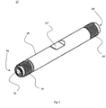
- Figs. 1 to 4 show a cylindrical pipe 11 with or without connection elements 13, 13'.
- the pipe 11 is, in particular, equipped as a chromatography column.
- a column of this type is used to receive a stationary phase (not shown) in the pipe interior 12, which a mobile phase (not shown) can flow through.
- the pipe interior 12 therefore forms a passage. If a substance mixture is fed to the mobile phase, the various constituents of the substance mixture separate, because of a different distribution of the constituents between the stationary and the mobile phase, into fractions transported at different speeds.
- the two ends of the pipe 11 are connected or can be connected, to connection elements 13,13'.
- These connection elements 13,13' are used to connect a feed or a discharge line (not shown) for sample material to the pipe, in particular to a chromatography column.
- each pipe end region 17, 17' has a thread (an external thread 19, 19', in particular, here), which can be screwed to a counter-thread (an internal thread 21, 21', in particular, here) of the connection element 13, 13'.
- a plug mechanism with an anti-withdrawal device for example a barbed hook.
- connection element 13, 13' (here also called a fitting) according to Figs. 1 to 4 has two connection points 23 and 25, or 23' and 25'; a first connection point 23, 23' is used for fastening on the pipe 11 and a second connection point 25, 25' is used for fastening on a feed or discharge line.
- a connection element 13, 13' is therefore used to connect the pipe 11 to a feed or discharge line. In the assembled state, it is possible to feed the pipe 11 with sample material at the end or to remove the material that has passed through the pipe passage and separated and to analyse it.
- a connection element 13, 13' contains at least one cylindrical base body 26 ( Fig. 4 ), in particular manufactured from metal, a fitting insert 37 and selectively a filter 27.
- the base body 26 consists of at least the two connection points 23 and 25, or 23' and 25', which are connected to one another by a bridge part 28 located in between.
- the two connection points of a connection element are optionally arranged coaxially with respect to one another.
- Each connection point 23, 25 can be equipped with a thread, in particular an internal thread 21 or 30, or another fastening structure.
- the fitting insert 37 is also called a pressed body here.
- the fitting insert 37 is advantageously produced from a plastics material.
- Figs. 2 and 4 show filters 27, 27', which are arranged upstream and downstream of the pipe passage 12.
- a filter 27, 27' can be fitted in the pipe end region 17, 17', the connection element 13, 13' or partially in both.
- the filter 27, 27' is preferably exchangeable.
- the pipe 11 consists, according to the invention at least of a metal casing 29 and an inlay 31.
- the ends of the pipe 11 have end faces 34, 34'. Faces which are visible in an axial plan view are called end faces here.
- the metal casing is manufactured from an inert metal or an inert metal alloy, preferably from high-grade steel, and the inlay 31, is manufactured from a plastics material.
- the inlay 31 consists of a plastics material tube which, as shown in Fig. 3 , for example, is drawn or pushed into the metal casing 29.
- the external diameter of the inlay 31 and the internal diameter of the metal casing 29 are substantially the same size, i.e. the inlay 31 is preferably seated in a taut manner in the metal casing 29.
- the external diameter of the inlay 31 can optionally be designed to be somewhat smaller than the internal diameter of the metal casing 29, in particular by a maximum of 100 micrometres, preferably a maximum of 50 micrometres, more preferably by a maximum of 5 micrometres.
- the inlay 31 and metal casing 29 are approximately the same length, the inlay 31 being dimensioned to ensure a tight pressure connection between the inlay 31 and connection elements 13, 13'.
- the metal casing 29 has end threads 19, 19', in particular external threads, which are used for connection to discharge or feed lines, this connection expediently being able to take place by means of a connection element 13, 13' connected in between.
- the two threads 19, 19' are preferably placed on the outside in the pipe end regions 17, 17'.
- a longitudinal section is shown through the pipe 11 and the screwed-on connection elements 13,13'.
- the pipe 11 comprises a casing 29, in particular made of metal, which is covered over its entire inside with an inlay 31.
- a depression 33 on the inside of the casing can be formed at the end face of the metal casing 29, said depression being covered with a sealing ring 35.
- the sealing ring 35 therefore rests on the lateral surface of the inlay 31 at the end, at least on the outside.
- the contact faces between the inlay 31 and sealing ring 35 are advantageously welded or optionally glued and therefore form an integral, i.e. one-piece or material-uniting bond.
- an integral connection i.e. a material-uniting connection
- the pipe end region 17, 17' with a thread 19, 19' is received by the connection element 13, 13' with a non-positive connection.
- the end face 36 of the inlay 31 with a sealing ring 35 abuts in the connection element 13, 13', at least partially, on an insert 37.
- This insert 37 advantageously also consists of a plastics material.
- the contact faces between the insert 37 and sealing ring 35 form an annular face.
- connection element 13, 13' When the pipe 11 and connection element 13, 13' are screwed, two plastics material faces therefore meet one another, and close under corresponding contact pressure, in a liquid-tight manner, optionally in a gas-tight manner.
- the pipe casing 29 and the connection elements 13,13' meet one another on the outside of the inlay.
- the end face 32 of the pipe casing meets a metal inner face of the connecting part 13, 13', so that with corresponding contact pressure and a corresponding orientation of the faces pressed against one another, this connection, which advantageously consists of two metal faces pressed against one another, is liquid-tight and optionally gas-tight.
- other constructions for the closure (optionally liquid-tight or gas-tight) between the metal pipe casing 29 and metal connection element 13,13' would, however, also be conceivable.
- the fitting insert 37 is configured in such a way that a feed or a discharge line can be inserted in a liquid-tight (optionally gas-tight) manner.
- a feed or discharge line also has a metal casing and an internal covering of plastics material.
- the second connection point 25, 25' of the connection element 13, 13' is configured in such a way that the two components of the feed or discharge line during connection to the connection element 13, 13' impinge on faces of the same material or similar material.
- the internal covering which advantageously consists of plastics material, can be connected to the fitting insert 37 in a liquid-tight, optionally gas-tight manner (for example by contact pressure), and the casing, which is advantageously metallic, is connectable to metallic regions of the connection element 13, 13', in particular in a liquid-tight manner (optionally in a gas-tight manner).
- Embodiments of the pipe end region 17 (also correspondingly 17') of a pipe 11 are shown enlarged in Figs. 5 , 6 and 7 - in particular in Fig. 5 , that embodiment, which is also contained in Fig. 4 , and alternative embodiments in Fig. 6 and 7 .
- the pipe substantially contains a metallic pipe casing 29, 29', which at the pipe end or at the end region, carries an external thread 19.
- the thread outlet 43 at the transition to the shaft may be configured as an indentation relative to the pipe casing external diameter of the shaft region 45.
- the thread outlet 47 at the end or near the end face can also have a reduced pipe casing external diameter in comparison to the shaft region 45.
- An inlay 31, 31' of plastics material is advantageously drawn as a tube into the metallic pipe casing 29, 29' or alternatively applied as a coating to the inside of the pipe casing 29, 29'.
- the inlay 31, 31' is reinforced at the end with a sealing ring 35 in a material-uniting manner.
- the two plastics materials of the inlay 31, 31' and sealing ring 35 are welded to one another and/or the sealing ring 35 was introduced by plastics material injection-moulding; alternatively, an adhesive connection is conceivable, for example.
- the sealing ring is matched in accordance with the application to the pipe casing 29, 29'.
- the sealing ring 35 is at least the same thickness as or thicker than, the wall thickness of the inlay 31, 31'.
- the external diameter of the sealing ring 35 is advantageously smaller than the external diameter of the pipe 11, advantageously smaller by at least 1 mm, more preferably smaller by at least 1.5 mm.
- the sealing ring 35 rests at least partially in a depression 33 on the internal wall of the pipe casing 29.
- the depression is open at the end face, so the sealing ring 35 can form an end face 36 with the inlay 31.
- a remaining edge region of the pipe casing 29 radially to the outside provides a type of support web 51.
- the inlay 31 and/or the sealing ring 35 project slightly in axial extension, for example preferably 0.1 mm to 2 mm, beyond the edge of the pipe casing 29, so these are compressed under pressing force and with the fitting insert 37 as the counter-piece, can form a gas-tight passage.
- the sealing ring 35 rests on the end face 32' of the pipe casing 29'.
- a support web 51 is therefore dispensed with in this embodiment variant, but could be provided on the connection element. Because of the advantageous material-uniting connection between the inlay 31 and sealing ring 35, the inlay 31 is reinforced and supported at its end projecting over the pipe casing 29'.
- the sealing ring 35 rests at least partially in a depression 33 on the internal wall of the pipe casing 29, as shown above in the embodiment according to Fig. 5 .
- the depression is open on the end face and optionally a remaining edge region of the pipe casing 29 radially to the outside provides a type of support web 51.
- the inlay 31' and/or the sealing ring 35 project slightly at the end in an axial extension beyond the edge of eh pipe casing 29.
- the filter 27 may alternatively be let into the pipe 11 at the end face. In this case, the filter 27 is expediently surrounded by the inlay 31', so the tightness is ensured.
- FIG. 8 A configuration of a positive bond of the pipe 11 and connection element 13 will be shown below by Fig. 8 .
- Fig. 8 A configuration of a positive bond of the pipe 11 and connection element 13 will be shown below by Fig. 8 .
- certain faces i.e. end faces
- the sealing ring 35 and fitting insert 37 or inlay 31 and fitting insert 37 are positively pressed onto one another.
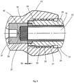
- these plastics material parts are locally pressed and compressed (in particular by a pressing distance 53), until opposing metal faces meet, so in the completely screwed state, the plastics material and metal faces meet one another in a sealing manner.
- Fig. 8 shows the inserted filter 27, which is seated in a recess (the fitting insert 37 here), which recess, toward the through-opening 41, forms a tapering funnel 55.
- the funnel region 55 remains free of filter material, so a through-flowing medium, when entering the filter region 27, easily distributes through the entire filter diameter and passes at as homogenous a speed as possible via the entire radial region out of the filter 27 into the pipe 11 and/or, coming from the pipe 11, when leaving the filter region 27, can flow away through the through-opening 41 without the formation of a jam in regions.
- connection element 13 A configuration of the connection element 13 will be shown in detail below with the aid of Fig. 9 .
- the metal casing 26 comprises the fitting insert 37, which can be inserted from the first end 23.
- the fitting insert 37 abuts on a first internal shoulder 56 of the metal casing 26.
- both the fitting insert 37 and the tubular metal casing 26, which has a second internal shoulder 57 form a joint face for a pipe 11 with a sealing ring 35.
- the two joint faces, according to the view, are preferably configured as joint faces that are approximately flush with one another.
- connection point 24 for the connection of the feed or discharge line is shown in Fig. 9 , in particular.
- the cylindrical recess 58 in the fitting insert 37 which recess 58 serves to receive a feed or discharge line, leads from the through-opening 41 to the opening of the second connection point 25.
- the inner covering of the feed or discharge line and fitting insert 37 should be able to undergo a positive press connection of plastics material on plastics material here.
- the connection element 13, on the inside provides at least one portion 59 with a metallic surface to positively receive a metallic casing of a feed or discharge line.
- the portion 59 is preferably funnel-shaped in order to ensure a positive and optionally liquid-tight and/or gas-tight connection.
- This connection can be configured as a screw connection.
- a detail of an assembled capillary device, in particular a chromatography column, will be shown below in Fig. 10 .
- the detail given of the device comprises the pipe 11 (i.e. a first capillary), a feed or discharge line 60 (i.e. a second capillary) and a connection element 13.
- a pipe end region 17 is closed together in a liquid-tight or gas-tight manner with the feed or discharge line 60.
- a feed or discharge line 60 is constructed of an (advantageously metallic) casing 61 and of an inner covering 62 (preferably made of plastics material).
- the end piece of the feed or discharge line 60 may advantageously carry a connection part 63 for screwing in.
- a useful connection part 63 may, for example, grip a feed or discharge line 60 if this feed or discharge line 60 is equipped with a thickened end portion 64.
- This end portion 64 is thickened and supported, for example, by a ring or a sleeve 65.
- the ring or sleeve 65 preferably consists of plastics material.
- the metal casing 61 in the end portion 64 is expediently slightly shortened compared with the inner covering 62 (advantageously by at least 1 to a maximum of 3 mm), so the inner covering 62 projects in the axial direction.
- This separate part region of the inner covering 62 also called a sealing portion 66 here, may advantageously undergo a material-uniting connection with the ring or sleeve 65.
- the material-uniting connection may be achieved in that, for example, the ring or the sleeve 65, which is turned over the end portion 64 during production is glued to the exposed inner covering 62, i.e. the sealing portion 66, and/or preferably welded, for example laser welded, at least where the sealing portion 66 of the feed or discharge line 60 meets the ring or sleeve 65.
- the ring or the sleeve 65 can be produced in that the end portion 64, in particular with the sealing portion 66, has a plastics material layer injected round it, so a material-uniting connection can optionally be produced at least between the plastics material inner covering 62 of the sealing portion 66 and the injected-on plastics material of the ring or the sleeve 65.
- a laser welding step may additionally be carried out with or after the injection-moulding therearound.
- connection part 63 is fitted with a widened cone 67, which is, on the one hand, suitable to prevent the feed or discharge line 60 thickened at the end (i.e. end portion 64) from being pulled out and allows a precisely fitting seat in the connection element 13.
- the cone 67 may be configured with a pipe extension 69, which encompasses the running-in line end over a certain region and supports it.
- the cone 67 may be made of metal in order to produce a metal-metal seal with the connection element 13.
- the transition from the fitting insert 37 to the feed or discharge line 60 is therefore also inwardly tightly closed (in a liquid-tight, optionally gas-tight manner) by a plastics material-plastics material connection and closed outwardly by a metal-metal connection.
- the assembled capillary device (in particular according to Fig. 10 ) contains a pipe 11, a feed or discharge line 60 and a connection element 13.
- the device is distinguished, in particular, in that it has tight (liquid-tight, optionally gas-tight) connection points, at which plastics material is pressed together on plastics material in a sealing manner. These points are firstly the contact face A between the sealing ring 35 and fitting insert 37 and, secondly, the contact face B between the ring or sleeve 64 of the feed or discharge line 60 and the fitting insert 37.
- the device is furthermore distinguished in that it has tight connection points, at which metal is pressed together on metal in a sealing manner.
- a bio-inert HPLC column consists of a metal column, in particular a high-grade steel column, with a fitted-in PAEK pipe inlay (in particular a PEEK pipe inlay).
- the inside is chemically sealed, i.e. in a liquid-tight and optionally gas-tight manner, (for example PEEK/PEEK) and the outside is sealed in a pressure-tight manner or hydraulically (metal/metal).
- a PEEK ring is fastened on the column end part on both sides as a seal with the aid of laser welding on the inlay.
- the fittings consist of high-grade steel on the outside and of a pressed-in PEEK insert on the inside.
- the sealing takes place with the PEEK column seal on the inside and with the metal edge of the column on the outside.
- the capillary connection of the fitting is also sealed chemically (PEEK/PEEK) on the inside and is hydraulically tight (metal/ metal) on the outside.
- the system according to the invention on the inside, in other words in the region which comes into contact with the sample, preferably consists completely of a PAEK material (preferably, for example, of PEEK).
- PAEK preferably, for example, of PEEK
- the sample thus only comes into contact with PAEK, in particular PEEK, and a chemical HPLC sample seal is furthermore achieved (in particular only by PEEK).
- the external diameter preferably consists completely of high-grade steel.
- a hydraulically pressure-tight high-grade steel housing is thus produced, which provides all the advantages of a pure high-grade steel column described at the outset.
- the system according to the invention has the following advantageous properties:
- the production process of the bio-inert HPLC column according to the invention expediently contains the following steps:
- the production process expediently contains the following steps:
- a pipe containing a metal casing 29 with an inlay 31 is disclosed here, which is characterised in that the inlay 31 is configured as a plastics material tube and is pushed or drawn into the metal casing 29 and a sealing ring 35 consisting of plastics material is connected, in each case, to the inlay 31 at the end.
- a connection to further system parts is possible, which is carry-over-free, inert on the inside, liquid-tight, optionally gas-tight, and pressure-tight.
- a connection element and a type of connection to connect the pipe to feed and/or discharge lines of a capillary system are also disclosed. Pipes, connection elements and connections of this type are advantageously used in low and high pressure systems, such as, for example, in an HPLC column. The use of such systems is particularly advantageous in in-vitro diagnostics and in liquid handling applications.
Landscapes
- Engineering & Computer Science (AREA)
- General Engineering & Computer Science (AREA)
- Immunology (AREA)
- Pathology (AREA)
- Analytical Chemistry (AREA)
- Biochemistry (AREA)
- General Health & Medical Sciences (AREA)
- General Physics & Mathematics (AREA)
- Physics & Mathematics (AREA)
- Chemical & Material Sciences (AREA)
- Life Sciences & Earth Sciences (AREA)
- Health & Medical Sciences (AREA)
- Mechanical Engineering (AREA)
- Treatment Of Liquids With Adsorbents In General (AREA)
- Physical Or Chemical Processes And Apparatus (AREA)
- Sampling And Sample Adjustment (AREA)
Description
- The invention relates to a pipe, in particular configured as a chromatography column, for example a high performance liquid chromatography column, which has a metal casing with an inlay. Furthermore, the invention relates to a connection element for connecting a pipe of this type to a feed or discharge line. The invention also relates to a connection system or low and high pressure system, in particular configured as a chromatography system, especially, for example, a high pressure liquid chromatography system, comprising at least one pipe of this type and optionally a connection element of this type. The invention furthermore relates to a connection for a capillary system, in particular an HPLC system, containing a plastics material pressed body with a through-opening.
- High performance liquid chromatography (HPLC) is an established method for the chemical analysis and separation of substance mixtures. The method belongs to the standard equipment of a laboratory in research and industry. In particular, this method tends to be used for in-vitro diagnostics. The basic principle is based on the different adherence energy of substances to be separated on a known substrate. For analysis, a substance mixture is brought into solution in a so-called mobile phase and the solution is then pressed at high pressure through a column of porous particles (stationary phase). Depending on the adsorption behaviour of the various substances on the stationary phase, the constituents of the substance mixture leave the separation column one after the other.
- There is a need in the area of HPLC and, quite particularly, for HPLC applications in the area of in-vitro diagnostics, for bio-inert HPLC hardware. At no point of the HPLC apparatus is an ion exchange to take place between a metal part and the sample to be analysed by chromatography. Substance adherences, such as, for example, of proteins, or carry-overs are also to be avoided. Pipe systems which are, in particular, inert and low in carry-overs would therefore be desirable.
- It has attempted, on the one hand, to solve these problems in that, for example, high-grade steel pipes were inertly coated on the inside or were provided with glass inlays. On the other hand, in the HPLC area, complete systems are generally used nowadays, containing columns, screw connections, frits and capillaries, which are manufactured completely from plastics material, in particular polyetheretherketone (PEEK).
- The following drawbacks are produced from using pure plastics material column systems:
- Only low pressures can be applied to the system for packing the column or for transportation of the sample through the column, as well as low operating pressures. Thus relatively long passage times of the sample result.
- Frequently desired micro columns are not possible, or only possible to a limited extent, because of the higher pressures required.
- Only pure PEEK columns are generally commercially available. Although frequently required so-called PEEKsil columns (composite of glass pipe encased by PEEK) are available, their connection generally has to firstly be adapted, which often causes problems for the user.
- The threads are often relatively weak because of the material properties of the PEEK and can only withstand a correspondingly low torque.
- The commercially available PEEK columns are expensive, as they are produced by a complex centrifugal method.
- The column dimensions have to have a specific size (standard). Deviations mean high tool costs.
- The following drawbacks are produced by using coated systems (coated high-grade steel):
- The production of a gap-free coating is difficult; in particular it is not practicable to prove a gap-free coating over the complete internal diameter of the system. Consequently there is no process reliability.
- With a different layer thickness, metal ions can diffuse into the sample at the points at which the coating is too thin.
- The sealing at the end face or the transition between the coated pipe and connection fitting is not ideally solved.
- The following drawbacks are produced from the use of glass inlay columns:
- Glass inlay can easily break or rupture and can therefore become untight.
- There is generally a gap between the glass inlay and high-grade steel and this leads to a break at elevated pressure. High pressures can therefore not be applied.
- The sealing at the end face or the transition between the HPLC column with the glass inlay and connection fitting is not yet ideally solved.
- The published application
WO 2011/076244 A1 relates to an assembly element for a fluidics device, in particular for applications in devices for high performance liquid chromatography. An assembly element of a fluid coupling for coupling a pipeline to a fluidics device is disclosed. The assembly element contains a pipeline with an inlay, the inlay being located in a cavity of a front side of the pipeline and projecting slightly out of the line. The inlay is used for sealing during coupling to a chromatography device. The pipeline, depending on the application, may have a plastics material (for example PEEK) on the inside. The drawback here is, in particular, that the connection takes place upon coupling over said inlay so that not only one joint is produced but simultaneously two joints between the pipeline and its coupling partner. Each additional connection point harbours the danger of contamination and carry-over of impurities. In addition - depending on the embodiment of the pipe - the effective connection face of the insert and innermost pipeline layer is optionally very small, which additionally reduces the reliability of the coupling system. - The published application
EP 2 315 022 A1 shows a chromatography column with a frit ring, frit holder and end connection. The sealing of this system extends over a plurality of joint connections between the pipe and frit ring, frit ring and frit holder as well as frit holder and end connection. With this structure, the numerous connection points (joint points) being produced during the coupling, are problematical with regard to a carry-over of impurities and contamination. - A biocompatible liquid chromatography column is described in the patent
US 5 736 036 . The inner pipe of the column is integral and can therefore not be pulled through the outer pipe or separated. An axial slipping of the inner pipe relative to the outer pipe is thus ruled out. In terms of manufacturing, restrictions are imposed by this structure. In particular, the inner pipe is introduced by a casting method. During casting, a material-uniting connection is formed between the outer and inner pipe. The drawback in the casting method are the increased manufacturing costs, which in particular also arise in that with the desired thickness variation of the inner pipe, the latter cannot easily be exchanged, but the column in each case has to be manufactured in various configurations. The outlay to produce various combinations of inlay thicknesses and column lengths and to have them in stock correspondingly has to be rated as high. In addition, because of the cast manufacturing, bubbles may form, which reduce the effective wall thickness of the inner pipe. In addition, checking for bubbles is difficult in the completed pipe composite. - The published application
US 2005/0199540 A1 shows a high performance liquid chromatography column. The disclosed HPLC column is formed with overlying concentric inner and outer tubes. The flow path is established via the inner tube bore that holds packed absorbent, end filters and capping sealing members, and end coupling members cooperate with the inner tube at its ends. The sealing and end coupling members have conventional configurations for establishing a sealed connection with capillary lines and their fittings, for the series flow testing use through the column. In particular a filter is butting against a packed absorbent and also overlaps and butts against the end of the inner tube and therefore is squeezed between a capping sealing member and the inner tube. - An object of the present invention is to provide in-vitro diagnostic systems or liquid handling systems or parts for use in systems of this type. Furthermore, it is an object of the present invention to provide an inert or bio-inert high performance liquid chromatography system (HPLC system), which does not have the drawbacks of the prior art or at least partially avoids them. In particular, one aim is to provide an inert HPLC column, which combines the advantages of the known plastics material columns and metal columns.
- This object is achieved by a pipe according to claim 1, preferably configured as a chromatography column, containing a tubular metal casing with an inlay and sealing ring. The pipe may be characterised in that the inlay is configured as a plastics material tube (or plastics material pipe) and is pushed or drawn into the metal casing and a sealing ring (in particular a sealing ring in each case), consisting of plastics material is connected to the inlay at the end face or at the end of the pipe. Because of said structure of the pipe, a liquid-tight or gas-tight connection to other system parts is optionally possible. The inlay can also be called a covering. The metal casing is thus covered on the inside with the covering (or the inlay). The advantages of this pipe are, in particular, its simple and economical manufacture. The metal casing and inlay are, in particular, not connected in a material uniting manner, but adjoin one another, optionally with a fit, in particular press fit.
- Further advantages and features of the invention emerge from the following description.
- The pipe is expediently used as a high performance liquid chromatography column (HPLC column). At each end of the pipe, a sealing ring mentioned is, in each case, expediently connected to the inlay.
- The inlay advantageously pushes through the sealing ring or the sealing rings or - expressed differently - the inlay is drawn through the sealing ring or the sealing rings. The sealing ring may adjoin the lateral surface of the inlay on the outside, or rest thereon. The inlay and sealing ring are connected to one another in a material-uniting manner. The advantages of this arrangement are that the inlay tube remains free at its end face in order to undergo a direct sealing connection with the part to be connected, only one joint point being produced per connection between the inlay and connection part. The sealing ring encompassing the inlay tube on the casing side on the one hand has a supporting effect on the inlay end region and, on the other hand, it widens the sealing face at the joint point to the connection part. In addition, the face between the sealing ring and inlay can be adapted or optimised by the choice of sealing ring length.
- The pipe according to the invention may be part of an in-vitro diagnostic system or a liquid handling system. Chemical analysis systems and preparative instruments are examples of liquid handling systems of this type and optionally in-vitro diagnostic systems.
- An annular depression is advantageously recessed on the end face or on the end face of the metal casing on the inside of the casing, which depressions receive the sealing ring. Optionally, an annular depression is in each case recessed at the two end faces or on the end face of the metal casing on the inside of the casing.
- Alternatively, the inlay projects on the end face, in particular at the two end faces of the metal casing, so that the sealing ring or the sealing rings adjoin the inlay on the outside (in particular so the sealing ring adjoins the lateral surface of the inlay on the outside), or encompass the inlay adjacently and are integrally connected thereto in a material-uniting manner.
- Advantageously, edge regions of the metal casing located radially outwardly on the end face are not occupied or covered by the sealing rings.
- The sealing ring may be applied to the metal casing and/or the inlay by injection-moulding. More preferably, the inlay and sealing material are welded, in particular laser-welded or glued, in order to produce an integral (i.e. one-piece or material-uniting) material bond.
- The material of the inlay and/or the sealing ring preferably contains a thermoplastics material, in particular selected from the group consisting of fluoroplastics (also called fluoropolymers), polyaryletherketones (PAEK) and mixtures thereof, the polyaryletherketones preferably furthermore being selected from the group consisting of polyetherketone (PEK), polyetheretherketone (PEEK) and polyetherketoneketone (PEKK), polyetheretherketone (PEEK) being preferred, and polytetrafluoroethylene (PTFE) being the preferred fluoroplastics material. More preferably, the plastics material of the inlay and the sealing ring consists of the same material group, or in particular of the same material, PEEK being preferred.
- In an alternative embodiment, the plastics material inlay may encase a glass capillary. The plastics material of an inlay of this type is preferably also selected from the group consisting of fluoroplastics and polyaryletherketones (PAEK). For example, a PEEK capillary may be used with an inner glass capillary. Polytetrafluoroethylene (PTFE) or a composite or a mixed material containing at least one PAEK plastics material and PTFE is also suitable, in particular for encasing the glass capillary.
- The wall thickness of the inlay is advantageously in the range from 0.05 mm to 2 mm, in particular in the range from 0.1 mm to 1 mm.
- The metal casing being used to support the inner plastics material parts preferably substantially consists of high-grade steel. In addition, the internal diameter of the metal casing is preferably in the range from 0.5 mm to 10 mm, more preferably in the range from 2 mm to 6mm.
- According to the present invention, there is no material-uniting connection between the metal casing and inlay. However, the possibility exists of producing a press fit between the inlay and metal casing with a corresponding selection of the outer inlay diameter and inner metal casing diameter for better slip-resistance, in that the inner metal casing diameter is selected to be slightly smaller than the outer inlay diameter.
- The internal diameter of the sealing ring expediently substantially corresponds to the external diameter of the inlay at the edge regions thereof. The inlay in the edge region is advantageously welded or glued to the inner wall of the sealing ring.
- A thread is expediently formed in at the pipe end region, in particular at each of the two pipe end regions. Other embodiments are conceivable, however.
- The above object is furthermore advantageously achieved by a connection element for connecting a pipe according to the invention, in particular a chromatography column such as, for example, a high performance liquid chromatography column, to a feed or discharge line, in particular a sample feed or sample discharge line. The connection element comprises a cylindrical metal casing. This metal casing comprises a first end, a centre piece and a second end, an internal thread being formed in at the first end, the second end being configured as a connection piece for the feed or discharge line and the centre piece containing a plastics material pressed body with a through-opening to receive one end of a feed or discharge line. The plastics material body can be inserted from the first end and abuts against a first internal shoulder of the metal casing. In the cavity of the first end, both the plastics material body and the tubular metal casing, which has a second internal shoulder, form a joint face for a pipe, in particular for a pipe of a chromatography column.
- At the end face toward the first end, a filter is preferably let into the plastics material pressed body, optionally in a flush manner.
- Furthermore, a connection system according to the invention (also called a low and high pressure system or low and high pressure line system here), in particular a chromatography system or high performance liquid chromatography system, is disclosed, which contains:
- (a) a pipe according to the above statements,
- (b) a first connection element, in particular according to the above statements, for the sealing connection of a feed line, in particular a sample feed line, and
- (c) a second connection element, in particular according to the above statements, for the sealing connection of a discharge line, in particular a sample discharge line.
- A connection system of this type or a low and high pressure system is inert relative to a sample material inasmuch as the plastics material used on the inside is inert under operating conditions (for example pressure and temperature) relative to the sample material. Systems which work at a pressure to a maximum of 1000 bar, preferably to a maximum of 500 bar, are called low pressure systems here. Systems, which are used at a pressure of 500 bar or more, in particular at a pressure from 1000 bar or more, are called high pressure systems here.
- A connection system of this type or low and high pressure system is free of metal surfaces on the sample passage side. The sample and metallic casing parts can therefore not contact one another, so an ion exchange, material adhesions, such as, for example, protein adhesions or a carry-over are avoided.
- Advantageously, a filter or a filter body is arranged in each case between the inlay and plastics material pressed body. The filter is preferably selected from the group containing the filter fabric, screen and frits, in particular metal frits, sintered metal frits and PEEK frits. The material of such filters is expediently inert with respect to the sample material to be tested.
- The plastics material pressed body and sealing ring are preferably dimensioned such, that they contact one another in a sealing manner. The external diameter of the plastics material pressed body expediently substantially corresponds to the external diameter of the sealing ring, in particular the external diameter of the respective sealing ring.
- Due to the construction, a first respective seal of plastics material on plastics material and a second respective seal of metal on metal advantageously exist between the pipe and each connection element.
- The connection system or low and high pressure system more preferably contains a feed and/or discharge line, the feed and/or discharge line preferably being configured as a plastics material tube (i.e. plastics material capillary) with a metal surround.
- In the assembled state, a first seal of plastics material on plastics material and a second seal of metal on metal may exist between the connection element and feed or discharge line.
- The respective first seal advantageously forms an inner seal and the respective second seal forms an outer seal. The inner seal here is optionally called a chemical seal and the outer seal is optionally called a hydraulic seal.
- The so-called connection system is advantageously used in a low and high pressure line system, for example in a chromatography system or a high performance liquid chromatography system. The connection system is therefore suitable, in particular, for liquid handling systems and in-vitro diagnostic systems.
- According to one exemplary embodiment, a pipe connection system for connecting two pipes is provided, in particular a pipe and a capillary (capillary configured here, for example, as a feed or discharge line), the pipe and the capillary each having a plastics material inlay, characterised by
- a cylindrical connection element, which, at its opposing ends, has a first and a second screw thread, and a receiving space in between for a pressed body,
- a pipe also having a screw thread, at the end face of which pipe a sealing ring is arranged, which is connected to the pipe inlay,
- a capillary with an inlay, which projects over the capillary end and defines a sealing portion,
- a screw part, which cooperates with one of the screw threads of the connection element and is used to fix the capillary on the connection element, and
- a pressed body for arrangement in the receiving space, which pressed body in the screwed state cooperates, on the one hand, with the sealing ring and, on the other hand, with the sealing portion, in a sealing manner.
- The pressed body advantageously has a recess to receive the sealing portion. The sealing portion and pressed body are advantageously connected to one another in a material uniting manner.
- The inlay is expediently formed by a plastics material tube, which is drawn into the pipe or into the capillary respectively.
- The above-mentioned specification of the aim is furthermore achieved with a connection according to the invention of two capillaries of a capillary system, in particular of an HPLC system, which connection is constructed from at least one plastics material pressed body with a through-opening and is characterised in that a plastics material capillary (preferably one plastics material capillary in each case on both sides of the through-opening) is connected to the through-opening, which plastics material capillary is encompassed at the end by a plastics material ring (i.e. a sealing ring), wherein at least the plastics material ring can be pressed or is pressed onto the plastics material pressed body. As a result, a tight, in particular liquid-tight, optionally gas-tight, seal of the connection is achieved.
- The plastics material capillary and plastics material ring preferably form an integral bond, in particular a material-uniting bond. A material-uniting connection may, for example, be produced by welding, in particular by laser welding and/or injection-moulding. Alternatively, the bond can be achieved by gluing.
- The contact faces of the plastics material ring (i.e. the sealing ring) on the plastics material pressed body thus produce seals of plastics material on plastics material.
- The plastics material pressed body and the plastics material capillaries are advantageously each encompassed by a metal casing. In this case, the metal casings are preferably connectable to one another, whereby a pressing power is produced in the connection.
- The contact faces between the metal casing on the metal casing thus produce seals of metal on metal.
- The plastics material used according to the invention is advantageously selected from the group of thermoplastics, in particular selected from fluoroplastics materials, polyaryletherketones (PAEK) and mixtures thereof, in particular selected from the group containing polytetrafluoroethylene (PTFE), polyetherketone (PEK), polyetheretherketone (PEEK), polyetherketoneketone (PEKK), polyetheretheretherketone (PEEEK), polyetherketoneetherketoneketone (PEKEKK), and polyetheretherketoneetherketone (PEEKEK), polyetherketone (PEK), polyetheretherketone (PEEK) and polyetherketoneketone (PEKK) being preferred and polyetheretherketone (PEEK) being most preferred.
- According to the invention, the described pipe, the described connection element, the described connection system or low and high pressure system and/or the described connection for a capillary system can be used in an in-vitro diagnostic system or a liquid handling system. The pipe according to the invention (optionally in connection with the connection element according to the invention and/or using the connection according to the invention) is particularly suitable for use as a chromatography column or as a high performance liquid chromatography column (HPLC column).
- An in-vitro diagnostic system or a liquid handling system, which is configured with a pipe according to the invention, optionally in connection with a connection element according to the invention, can be used, because of its inert properties over a broad application area.
- Other advantages and features of the invention emerge from the following description of exemplary embodiments with reference to figures. Preferred features mentioned may be implemented in any combination - as long as they are not mutually exclusive. In the drawings, schematically:
- Fig. 1:
- shows a perspective view of a system according to the invention with a chromatography column and connection parts;
- Fig. 2:
- shows a perspective view of a disassembled system according to the invention with a chromatography column, two filters and two connection parts;
- Fig. 3:
- shows a chromatography column according to the invention as in
Fig. 2 ; - Fig. 4:
- shows a longitudinal section through a system with a chromatography column, two filters and two connection parts;
- Fig. 5:
- shows a pipe end region according to the invention in longitudinal section of an embodiment as in
Fig. 4 ; - Fig. 6:
- shows an alternative pipe end region according to the invention in longitudinal section;
- Fig. 7:
- shows a further alternative pipe end region according to the invention in longitudinal section;
- Fig. 8:
- shows a detail containing a pipe end region according to
Fig. 5 , which is screwed to a connection element, in longitudinal section; - Fig. 9:
- shows a longitudinal section of a connection element;
- Fig. 10:
- shows a detail of a capillary device containing a connection element, which is connected at a first end to a pipe end and, at its second end, to a discharge or a feed line, in longitudinal section.
- The same reference numerals stand for the same or functionally the same elements below. An additional apostrophe is used to distinguish a plurality of or alternative elements.
-
Figs. 1 to 4 show acylindrical pipe 11 with or withoutconnection elements 13, 13'. Thepipe 11 is, in particular, equipped as a chromatography column. A column of this type is used to receive a stationary phase (not shown) in thepipe interior 12, which a mobile phase (not shown) can flow through. Thepipe interior 12 therefore forms a passage. If a substance mixture is fed to the mobile phase, the various constituents of the substance mixture separate, because of a different distribution of the constituents between the stationary and the mobile phase, into fractions transported at different speeds. The two ends of thepipe 11 are connected or can be connected, toconnection elements 13,13'. Theseconnection elements 13,13' are used to connect a feed or a discharge line (not shown) for sample material to the pipe, in particular to a chromatography column. For easier assembly, tool engagement points 15, 15', 15", which favour the holding and therefore the screwing of thepipe 11 andconnection element 13, 13', are formed on thepipe 11 and on theconnection elements 13, 13'. For example, eachpipe end region 17, 17' has a thread (anexternal thread 19, 19', in particular, here), which can be screwed to a counter-thread (aninternal thread 21, 21', in particular, here) of theconnection element 13, 13'. Alternatively, other types of connection could be used, such as, for example, a plug mechanism with an anti-withdrawal device (for example a barbed hook). - Each
connection element 13, 13' (here also called a fitting) according toFigs. 1 to 4 has twoconnection points first connection point 23, 23' is used for fastening on thepipe 11 and asecond connection point 25, 25' is used for fastening on a feed or discharge line. Aconnection element 13, 13' is therefore used to connect thepipe 11 to a feed or discharge line. In the assembled state, it is possible to feed thepipe 11 with sample material at the end or to remove the material that has passed through the pipe passage and separated and to analyse it. Aconnection element 13, 13' contains at least one cylindrical base body 26 (Fig. 4 ), in particular manufactured from metal, afitting insert 37 and selectively afilter 27. Thebase body 26 consists of at least the twoconnection points bridge part 28 located in between. The two connection points of a connection element are optionally arranged coaxially with respect to one another. Eachconnection point internal thread fitting insert 37 is also called a pressed body here. Thefitting insert 37 is advantageously produced from a plastics material. -
Figs. 2 and4 show filters 27, 27', which are arranged upstream and downstream of thepipe passage 12. Afilter 27, 27' can be fitted in thepipe end region 17, 17', theconnection element 13, 13' or partially in both. Thefilter 27, 27' is preferably exchangeable. - The
pipe 11 consists, according to the invention at least of ametal casing 29 and aninlay 31. The ends of thepipe 11 have end faces 34, 34'. Faces which are visible in an axial plan view are called end faces here. The metal casing is manufactured from an inert metal or an inert metal alloy, preferably from high-grade steel, and theinlay 31, is manufactured from a plastics material. Theinlay 31 consists of a plastics material tube which, as shown inFig. 3 , for example, is drawn or pushed into themetal casing 29. The external diameter of theinlay 31 and the internal diameter of themetal casing 29 are substantially the same size, i.e. theinlay 31 is preferably seated in a taut manner in themetal casing 29. Alternatively, the external diameter of theinlay 31 can optionally be designed to be somewhat smaller than the internal diameter of themetal casing 29, in particular by a maximum of 100 micrometres, preferably a maximum of 50 micrometres, more preferably by a maximum of 5 micrometres. Theinlay 31 andmetal casing 29 are approximately the same length, theinlay 31 being dimensioned to ensure a tight pressure connection between theinlay 31 andconnection elements 13, 13'. In a preferred embodiment, themetal casing 29 hasend threads 19, 19', in particular external threads, which are used for connection to discharge or feed lines, this connection expediently being able to take place by means of aconnection element 13, 13' connected in between. The twothreads 19, 19' are preferably placed on the outside in thepipe end regions 17, 17'. - In
Fig.4 , a longitudinal section is shown through thepipe 11 and the screwed-onconnection elements 13,13'. Thepipe 11 comprises acasing 29, in particular made of metal, which is covered over its entire inside with aninlay 31. As can be seen from the enlarged view inFig. 5 , adepression 33 on the inside of the casing can be formed at the end face of themetal casing 29, said depression being covered with a sealingring 35. The sealingring 35 therefore rests on the lateral surface of theinlay 31 at the end, at least on the outside. The contact faces between theinlay 31 and sealingring 35 are advantageously welded or optionally glued and therefore form an integral, i.e. one-piece or material-uniting bond. If the sealingring 35 is introduced into thedepression 33 by injection-moulding, an integral connection (i.e. a material-uniting connection) can optionally already be formed during the injection-moulding production, which, depending on the application, makes additional welding superfluous. Thepipe end region 17, 17' with athread 19, 19' is received by theconnection element 13, 13' with a non-positive connection. The end face 36 of theinlay 31 with a sealingring 35 abuts in theconnection element 13, 13', at least partially, on aninsert 37. Thisinsert 37 advantageously also consists of a plastics material. The contact faces between theinsert 37 and sealingring 35 form an annular face. When thepipe 11 andconnection element 13, 13' are screwed, two plastics material faces therefore meet one another, and close under corresponding contact pressure, in a liquid-tight manner, optionally in a gas-tight manner. During screwing, thepipe casing 29 and theconnection elements 13,13' meet one another on the outside of the inlay. Advantageously, theend face 32 of the pipe casing meets a metal inner face of the connectingpart 13, 13', so that with corresponding contact pressure and a corresponding orientation of the faces pressed against one another, this connection, which advantageously consists of two metal faces pressed against one another, is liquid-tight and optionally gas-tight. However, other constructions for the closure (optionally liquid-tight or gas-tight) between themetal pipe casing 29 andmetal connection element 13,13' would, however, also be conceivable. - By screwing or pressing the
pipe 11 to or onto theconnection element 13, 13', a liquid-tight (optionally gas-tight) through-passage is therefore produced, which leads from the interior of theinlay 31 through thefilter 27 into a fine through-opening 41 in thefitting insert 37. - On the opposite side of the through-
opening 41, thefitting insert 37 is configured in such a way that a feed or a discharge line can be inserted in a liquid-tight (optionally gas-tight) manner. Advantageously, a feed or discharge line also has a metal casing and an internal covering of plastics material. Thesecond connection point 25, 25' of theconnection element 13, 13' is configured in such a way that the two components of the feed or discharge line during connection to theconnection element 13, 13' impinge on faces of the same material or similar material. In other words, the internal covering, which advantageously consists of plastics material, can be connected to thefitting insert 37 in a liquid-tight, optionally gas-tight manner (for example by contact pressure), and the casing, which is advantageously metallic, is connectable to metallic regions of theconnection element 13, 13', in particular in a liquid-tight manner (optionally in a gas-tight manner). - The configuration of the
pipe end regions 17 and alternative configurations of the pipe end regions 17ʺ and 17‴ will be described below with the aid ofFigs. 5 ,6 and7 . - Embodiments of the pipe end region 17 (also correspondingly 17') of a
pipe 11 are shown enlarged inFigs. 5 ,6 and7 - in particular inFig. 5 , that embodiment, which is also contained inFig. 4 , and alternative embodiments inFig. 6 and7 . The pipe substantially contains ametallic pipe casing 29, 29', which at the pipe end or at the end region, carries anexternal thread 19. Thethread outlet 43 at the transition to the shaft may be configured as an indentation relative to the pipe casing external diameter of theshaft region 45. Thethread outlet 47 at the end or near the end face can also have a reduced pipe casing external diameter in comparison to theshaft region 45. Aninlay 31, 31' of plastics material is advantageously drawn as a tube into themetallic pipe casing 29, 29' or alternatively applied as a coating to the inside of thepipe casing 29, 29'. Theinlay 31, 31' is reinforced at the end with a sealingring 35 in a material-uniting manner. Advantageously, the two plastics materials of theinlay 31, 31' and sealingring 35 are welded to one another and/or the sealingring 35 was introduced by plastics material injection-moulding; alternatively, an adhesive connection is conceivable, for example. - The sealing ring is matched in accordance with the application to the
pipe casing 29, 29'. According to the advantageous embodiment shown, the sealingring 35 is at least the same thickness as or thicker than, the wall thickness of theinlay 31, 31'. The external diameter of the sealingring 35 is advantageously smaller than the external diameter of thepipe 11, advantageously smaller by at least 1 mm, more preferably smaller by at least 1.5 mm. - In the embodiment of a
pipe end region 17 according toFig. 5 , the sealingring 35 rests at least partially in adepression 33 on the internal wall of thepipe casing 29. - The depression is open at the end face, so the sealing
ring 35 can form anend face 36 with theinlay 31. A remaining edge region of thepipe casing 29 radially to the outside provides a type ofsupport web 51. Optionally, theinlay 31 and/or the sealingring 35 project slightly in axial extension, for example preferably 0.1 mm to 2 mm, beyond the edge of thepipe casing 29, so these are compressed under pressing force and with thefitting insert 37 as the counter-piece, can form a gas-tight passage. - In the alternative embodiment of a
pipe end region 17" according toFig. 6 , the sealingring 35 rests on the end face 32' of the pipe casing 29'. Asupport web 51, as shown inFig. 5 , is therefore dispensed with in this embodiment variant, but could be provided on the connection element. Because of the advantageous material-uniting connection between theinlay 31 and sealingring 35, theinlay 31 is reinforced and supported at its end projecting over the pipe casing 29'. - In the embodiment of a
pipe end region 17‴ according toFig. 7 , the sealingring 35 rests at least partially in adepression 33 on the internal wall of thepipe casing 29, as shown above in the embodiment according toFig. 5 . Advantageously, the depression is open on the end face and optionally a remaining edge region of thepipe casing 29 radially to the outside provides a type ofsupport web 51. Optionally, the inlay 31' and/or the sealingring 35 project slightly at the end in an axial extension beyond the edge of ehpipe casing 29. As shown inFig. 7 , thefilter 27 may alternatively be let into thepipe 11 at the end face. In this case, thefilter 27 is expediently surrounded by the inlay 31', so the tightness is ensured. Alternative embodiment variants are conceivable, in which the filter is partially let into the inlay 31' and therefore into thepipe 11 and partially into thefitting insert 37 of theconnection element 13. However, it is important in all the variants that the structural configuration of theinlay 31, 31' with thefitting insert 37 allows a positive and gas-tight connection, for example by screwing or pressing thepipe 11 andconnection element 13. At the same time, a positive and optionally gas-tight connection should preferably also be adjusted between the metal faces of thepipe casing 29 and theconnection element 13. - A configuration of a positive bond of the
pipe 11 andconnection element 13 will be shown below byFig. 8 . In this view, it is possible to see, above all, the state when thepipe 11 andconnection element 13 are screwed. In particular, it can be seen that certain faces (i.e. end faces) of the sealingring 35 andfitting insert 37 orinlay 31 andfitting insert 37 are positively pressed onto one another. Because of the certain resilience of the plastics material of theinlay 31, sealingring 35 andfitting insert 37, it is to be expected that with complete screwing, these plastics material parts are locally pressed and compressed (in particular by a pressing distance 53), until opposing metal faces meet, so in the completely screwed state, the plastics material and metal faces meet one another in a sealing manner. - Furthermore,
Fig. 8 shows the insertedfilter 27, which is seated in a recess (thefitting insert 37 here), which recess, toward the through-opening 41, forms a taperingfunnel 55. Advantageously, thefunnel region 55 remains free of filter material, so a through-flowing medium, when entering thefilter region 27, easily distributes through the entire filter diameter and passes at as homogenous a speed as possible via the entire radial region out of thefilter 27 into thepipe 11 and/or, coming from thepipe 11, when leaving thefilter region 27, can flow away through the through-opening 41 without the formation of a jam in regions. - A configuration of the
connection element 13 will be shown in detail below with the aid ofFig. 9 . Themetal casing 26 comprises thefitting insert 37, which can be inserted from thefirst end 23. Thefitting insert 37 abuts on a firstinternal shoulder 56 of themetal casing 26. In the cavity of thefirst end 23, both thefitting insert 37 and thetubular metal casing 26, which has a secondinternal shoulder 57, form a joint face for apipe 11 with a sealingring 35. The two joint faces, according to the view, are preferably configured as joint faces that are approximately flush with one another. - A possible embodiment of the second connection point 24 for the connection of the feed or discharge line is shown in
Fig. 9 , in particular. Thecylindrical recess 58 in thefitting insert 37, whichrecess 58 serves to receive a feed or discharge line, leads from the through-opening 41 to the opening of thesecond connection point 25. The inner covering of the feed or discharge line andfitting insert 37 should be able to undergo a positive press connection of plastics material on plastics material here. Following therecess 58, theconnection element 13, on the inside, provides at least oneportion 59 with a metallic surface to positively receive a metallic casing of a feed or discharge line. Theportion 59 is preferably funnel-shaped in order to ensure a positive and optionally liquid-tight and/or gas-tight connection. This connection can be configured as a screw connection. - A detail of an assembled capillary device, in particular a chromatography column, will be shown below in
Fig. 10 . The detail given of the device comprises the pipe 11 (i.e. a first capillary), a feed or discharge line 60 (i.e. a second capillary) and aconnection element 13. With the aid of theconnection element 13, apipe end region 17 is closed together in a liquid-tight or gas-tight manner with the feed ordischarge line 60. A feed ordischarge line 60 is constructed of an (advantageously metallic)casing 61 and of an inner covering 62 (preferably made of plastics material). The end piece of the feed ordischarge line 60 may advantageously carry aconnection part 63 for screwing in. Auseful connection part 63 may, for example, grip a feed ordischarge line 60 if this feed ordischarge line 60 is equipped with athickened end portion 64. - This
end portion 64 is thickened and supported, for example, by a ring or asleeve 65. The ring orsleeve 65 preferably consists of plastics material. Themetal casing 61 in theend portion 64 is expediently slightly shortened compared with the inner covering 62 (advantageously by at least 1 to a maximum of 3 mm), so theinner covering 62 projects in the axial direction. This separate part region of theinner covering 62, also called a sealingportion 66 here, may advantageously undergo a material-uniting connection with the ring orsleeve 65. The material-uniting connection may be achieved in that, for example, the ring or thesleeve 65, which is turned over theend portion 64 during production is glued to the exposedinner covering 62, i.e. the sealingportion 66, and/or preferably welded, for example laser welded, at least where the sealingportion 66 of the feed ordischarge line 60 meets the ring orsleeve 65. Alternatively, the ring or thesleeve 65 can be produced in that theend portion 64, in particular with the sealingportion 66, has a plastics material layer injected round it, so a material-uniting connection can optionally be produced at least between the plastics material inner covering 62 of the sealingportion 66 and the injected-on plastics material of the ring or thesleeve 65. In order to promote the integral connection, a laser welding step may additionally be carried out with or after the injection-moulding therearound. - The
connection part 63 is fitted with a widenedcone 67, which is, on the one hand, suitable to prevent the feed ordischarge line 60 thickened at the end (i.e. end portion 64) from being pulled out and allows a precisely fitting seat in theconnection element 13. Thecone 67 may be configured with apipe extension 69, which encompasses the running-in line end over a certain region and supports it. In particular, thecone 67 may be made of metal in order to produce a metal-metal seal with theconnection element 13. The transition from thefitting insert 37 to the feed ordischarge line 60 is therefore also inwardly tightly closed (in a liquid-tight, optionally gas-tight manner) by a plastics material-plastics material connection and closed outwardly by a metal-metal connection. - To summarise, the assembled capillary device (in particular according to
Fig. 10 ) contains apipe 11, a feed ordischarge line 60 and aconnection element 13. The device is distinguished, in particular, in that it has tight (liquid-tight, optionally gas-tight) connection points, at which plastics material is pressed together on plastics material in a sealing manner. These points are firstly the contact face A between the sealingring 35 andfitting insert 37 and, secondly, the contact face B between the ring orsleeve 64 of the feed ordischarge line 60 and thefitting insert 37. The device is furthermore distinguished in that it has tight connection points, at which metal is pressed together on metal in a sealing manner. These points are firstly the contact face C between thesupport web 51 and thebase body 26 of the connection element 13 (or optionally another face between thepipe casing 29 and connection element 13) and, secondly, the contact face D between thecone 67 andbase body 26 of theconnection element 13. At least the portions of these contact faces mentioned, which do not run parallel to the axial direction, have a sealing effect because of pressing forces. - In one exemplary embodiment, a bio-inert HPLC column according to the invention consists of a metal column, in particular a high-grade steel column, with a fitted-in PAEK pipe inlay (in particular a PEEK pipe inlay). The inside is chemically sealed, i.e. in a liquid-tight and optionally gas-tight manner, (for example PEEK/PEEK) and the outside is sealed in a pressure-tight manner or hydraulically (metal/metal).
- In order to chemically seal a gap between the PEEK inlay and high-grade steel column, a PEEK ring is fastened on the column end part on both sides as a seal with the aid of laser welding on the inlay.
- The fittings consist of high-grade steel on the outside and of a pressed-in PEEK insert on the inside. Thus the sealing takes place with the PEEK column seal on the inside and with the metal edge of the column on the outside. The capillary connection of the fitting is also sealed chemically (PEEK/PEEK) on the inside and is hydraulically tight (metal/ metal) on the outside.
- The system according to the invention, on the inside, in other words in the region which comes into contact with the sample, preferably consists completely of a PAEK material (preferably, for example, of PEEK). The sample thus only comes into contact with PAEK, in particular PEEK, and a chemical HPLC sample seal is furthermore achieved (in particular only by PEEK).
- Thus the system according to the invention has all the advantages which a pure HPLC-PEEK system described at the outset entails.
- The external diameter preferably consists completely of high-grade steel. A hydraulically pressure-tight high-grade steel housing is thus produced, which provides all the advantages of a pure high-grade steel column described at the outset.
- To summarise, the system according to the invention has the following advantageous properties:
- On the outside, a closed high-grade steel casing exists. Different parts are screwed in a pressure-tight manner, for example by means of fittings.
- On the inside, i.e. on the sample side, all the faces are 100% metal-free.
- On the inside, only the high temperature-resistant plastics material used, in particular only one type of high temperature-resistant plastics material, comes into contact with the sample material. The insides preferably only consist of PEEK.
- The system is highly bio-inert.
- No ion exchange can occur between the sample and the high-grade steel casing.
- The torque power of the fittings corresponds to that of a thread torque of high-grade steel.
- The stability of the system is guaranteed up to a pressure of 1000 bar and higher.
- Because of the high-grade steel casing placed on the outside, the system is pressure tight or hydraulically tight on the outside and because of the plastics material that is welded, glued, pressed and/or applied by being injection-moulded around, the system is chemically tight or materially-united on the inside, so that no liquid and optionally no gas can penetrate.
- The production process of the bio-inert HPLC column according to the invention expediently contains the following steps:
- A metal casing, in particular configured as a high-grade steel pipe, containing two end faces and an inner face with at least a first internal diameter and a certain length, is provided to produce a column.
- An inlay made of plastics material (for example a PAEK pipe, preferably a PEEK pipe) is inserted or fitted into the internal diameter of the metal casing. An inlay is used here, which is longer than the metal casing, or which is at least longer than the inner face with the first internal diameter of the metal casing in its longitudinal extent.
- A sealing ring is placed in or pressed onto the end faces of the metal casing and adjacent to the inlay. The sealing ring also consists of plastics material (for example of a PAEK, preferably also of PEEK).
- The sealing ring is then advantageously welded to the inlay, for example by laser welding (alternatively, a ring of plastics material can be injected (i.e. by injection-moulding)), so that the inlay and sealing ring combined, at the end face on the two column ends, in each case form a sealing face, which is used as a transition to a fitting. These sealing faces are advantageously located in front of the respective end faces of the metal casing.
- In a particularly advantageous production process of the bio-inert HPLC column according to the invention, the production process expediently contains the following steps:
- A metal casing, in particular configured as a high-grade steel pipe, is advantageously provided with an inner depression on both sides on the pipe ends or casing ends.
- An inlay made of plastics material (for example a PAEK pipe, preferably a PEEK pipe) is inserted or fitted into the internal diameter of the column.
- A sealing ring is placed in or pressed into the depression of the metal casing and adjacent to the inlay. The sealing ring also consists of plastics material (for example of a PAEK, preferably also of PEEK).
- The sealing ring is then advantageously welded to the inlay, for example by laser welding (alternatively, a ring of plastics material can be injected (i.e. by injection-moulding)), so that the inlay and sealing ring combined, at the end face on the two column ends, in each case form a sealing face, which is used as a transition to a fitting.
- The production process of a bio-inert HPLC screw connection (also called an HPLC fitting here) can proceed as follows:
- A cylindrical pipe-shaped metal body, in particular a high-grade steel body, is machined by turning and provided at each end with an internal thread.
- A plastics material inlay, preferably a PEEK inlay, is produced, by machining by turning.
- A frit, in particular a PEEK frit, is pressed into the inlay.
- The inlay, before or after the pressing with the frit, is pressed into the metal body.
- In summary, a pipe containing a
metal casing 29 with aninlay 31 is disclosed here, which is characterised in that theinlay 31 is configured as a plastics material tube and is pushed or drawn into themetal casing 29 and a sealingring 35 consisting of plastics material is connected, in each case, to theinlay 31 at the end. Because of said structure, a connection to further system parts is possible, which is carry-over-free, inert on the inside, liquid-tight, optionally gas-tight, and pressure-tight. A connection element and a type of connection to connect the pipe to feed and/or discharge lines of a capillary system are also disclosed. Pipes, connection elements and connections of this type are advantageously used in low and high pressure systems, such as, for example, in an HPLC column. The use of such systems is particularly advantageous in in-vitro diagnostics and in liquid handling applications. -
- 11
- pipe
- 12
- pipe interior, pipe passage
- 13,13'
- connection element
- 15, 15', 15"
- tool engagement point
- 17, 17', 17", 17‴
- pipe end region
- 19,19'
- thread, in particular external thread
- 21, 21'
- thread, in particular internal thread
- 23, 23'
- first connection point
- 25, 25'
- second connection point
- 26
- base body of a connection element configured as a metal casing
- 27
- filter
- 28
- bridge part, also called centre piece, of the base body
- 29, 29'
- pipe-shaped metal casing, pipe casing, in particular produced from metal
- 30
- thread, in particular internal thread
- 31, 31'
- inlay (can also be called a covering), arranged in the pipe casing
- 32, 32'
- end face of the pipe casing
- 33
- depression or recess, in particular on the inside of the casing, beginning at the end face of the pipe casing or metal casing
- 34, 34'
- end faces
- 35
- sealing ring
- 36
- end face of the inlay or of the sealing ring
- 37
- insert, also called fitting insert or pressed body
- 41
- through-opening
- 43
- first thread outlet
- 45
- shaft region
- 47
- second thread outlet
- 51
- support web
- 53
- pressing distance
- 55
- funnel
- 56
- first internal shoulder of the base body
- 57
- second internal shoulder of the base body
- 58
- cylindrical recess
- 59
- funnel-shaped connection portion
- 60
- feed and discharge line
- 61
- casing of the feed and discharge line, in particular made of metal
- 62
- inner covering of the feed or discharge line, in particular made of plastics material
- 63
- connection part
- 64
- end portion
- 65
- ring or sleeve, in particular made of plastics material, in particular sealing ring
- 66
- sealing portion, i.e. part region of the inner covering of the feed or discharge line projecting with respect to the casing
- 67
- cone or cone piece, in particular made of metal
- 69
- pipe extension of the cone, in particular made of metal
Claims (15)
- Pipe, comprising a tubular metal casing (29, 29') with an inlay (31) configured as a tube in the metal casing (29, 29') and with a sealing made of plastics material, wherein- the inlay tube (31) is made of plastics material and the sealing is configured as a ring (35), which is connected to the inlay (31) in a material-uniting manner, characterized in that- the sealing ring (35) encompasses the inlay tube (31) on the inlay tube's end region by adjoining the lateral surface of the inlay tube, and- the inlay (31) and sealing ring (35) combined form an end face (36).
- Pipe according to preceding claim 1, wherein an annular depression (33) is recessed on the inside of the casing (29) on the at least one end face (34, 34') of the metal casing (29), which depression (33) receives the sealing ring (35).
- Pipe according to any one of the preceding claims, wherein the inlay (31) and sealing ring (35) are welded, laser-welded or glued or the sealing ring is injection-moulded in order to produce an integral material bond.
- Pipe according to any one of the preceding claims, wherein the material of the inlay (31) and/or of the sealing ring (35) contains a thermoplastic material, in particular selected from the group consisting of fluoroplastics, polyaryletherketones (PAEK) and mixtures thereof, preferably selected from the group consisting of polyetherketone (PEK), polyetheretherketone (PEEK), polyetherketoneketone (PEKK) and polytetrafluoroethylene (PTFE), polyetheretherketone (PEEK) being preferred.
- Pipe according to any one of the preceding claims, wherein the plastics material of the inlay (31) and of the sealing ring (35) is the same, PEEK being preferred.
- Pipe according to any one of the preceding claims, wherein the metal casing (29, 29') consists of high-grade steel.
- Pipe according to any one of the preceding claims, wherein the inlay (31) encases a glass capillary.
- Connection system, containing(a) a pipe (11) according to any one of claim 1 to 7,(b) a first connection element (13) for connecting the pipe (11) with a feed line (60), and(c) a second connection element (13') for connecting the pipe (11) with a discharge line.
- Connection system according to the claim 8, wherein at least one connection element (13) , preferably both connection elements (13, 13') comprise a metallic base body (26), the metallic base body (26) comprising a first end (23), a centre piece (28) and a second end (25), an internal thread (21) being formed in a cavity at the first end (23), the second end (25) being configured as a connection piece for a feed or discharge line and the centre piece (28) comprising a fitting insert (37) made from a plastics material with a through-opening (41) to receive one end of a feed or discharge line (60), wherein the fitting insert (37) can be inserted from the first end and abuts against a first internal shoulder (56) of the metallic base body (26) and, in the cavity of the first end (23), both the fitting insert (37) and the metallic base body (26), which has a second internal shoulder (57), form an abutting face for said pipe (11).
- Connection system according to claim 9, wherein, when the pipe (11) and the connection element (13) are connected, then between the sealing ring (35) and the fitting insert (37) plastics material is pressed on plastics material in a sealing manner forming a first seal (A) of plastics material on plastics material and between the metal casing (29) and the metallic base body (26) of the connection element (13) metal is pressed on metal in a sealing manner forming a second seal (C) of metal on metal.
- Connection system according to any one of claims 8 to 10, wherein the system further contains a feed and/or discharge line (60), the feed and/or discharge line (60) preferably being configured as a plastics material tube with a metal surround.
- Connection system according to claim 11, wherein, in the assembled state, when the connection element (13) and a the feed or discharge line (60) are connected, then between a ring or sleeve (64) of the feed or discharge line (60) and the fitting insert (37) plastics material is pressed on plastics material in a sealing manner forming a first seal (B) of plastics material on plastics material and between a metallic cone (67) of a connection part 63 of the feed or discharge line (60) and the metallic base body (26) of the connection element 13 metal is pressed on metal in a sealing manner forming a second seal (D) of metal on metal.
- Connection system according to any one of claims 10 to 12, wherein the respective first seal (A, B) forms an inner seal and the respective second seal (C, D) forms an outer seal.
- An in-vitro diagnostic system, a chemical analysis system or a preparative instrument comprising a pipe according to anyone of claims 1-7 or a connection system according to anyone of claims 8 to 13.
- Use of a pipe according to any one of claims 1-7 as a chromatography column, more preferably as a high performance liquid chromatography column.
Applications Claiming Priority (2)
| Application Number | Priority Date | Filing Date | Title |
|---|---|---|---|
| CH001337/2011A CH705381B1 (en) | 2011-08-15 | 2011-08-15 | Tube containing metal jacket with plastic inlay for use as a chromatography column, especially as an HPLC column |
| PCT/IB2012/001629 WO2013024345A1 (en) | 2011-08-15 | 2012-08-09 | Pipe containing a metal casing with a plastics material inlay for use in low and high pressure applications, in particular as an hplc column |
Publications (2)
| Publication Number | Publication Date |
|---|---|
| EP2745104A1 EP2745104A1 (en) | 2014-06-25 |
| EP2745104B1 true EP2745104B1 (en) | 2022-01-26 |
Family
ID=46888492
Family Applications (1)
| Application Number | Title | Priority Date | Filing Date |
|---|---|---|---|
| EP12762041.7A Active EP2745104B1 (en) | 2011-08-15 | 2012-08-09 | Pipe containing a metal casing with a plastics material inlay for use in low and high pressure applications, in particular as an hplc column |
Country Status (4)
| Country | Link |
|---|---|
| US (1) | US9562879B2 (en) |
| EP (1) | EP2745104B1 (en) |
| CH (1) | CH705381B1 (en) |
| WO (1) | WO2013024345A1 (en) |
Families Citing this family (17)
| Publication number | Priority date | Publication date | Assignee | Title |
|---|---|---|---|---|
| WO2012177403A1 (en) * | 2011-06-20 | 2012-12-27 | Waters Technologies Corporation | Low carryover high pressure fluidic fitting |
| US10060560B2 (en) * | 2012-07-17 | 2018-08-28 | Waters Technologies Corporation | High pressure fitting for supercritical fluid chromatography |
| US9201049B2 (en) * | 2013-03-13 | 2015-12-01 | Idex Health & Science Llc | Connector with structural reinforcement and biocompatible fluid passageway |
| WO2014197783A1 (en) * | 2013-06-07 | 2014-12-11 | Waters Technologies Corporation | Chromatographic filter |
| CH708952A3 (en) * | 2013-12-13 | 2015-07-31 | Möller Medical Gmbh | Ceramic filter cartridge for chromatography applications, in particular HPLC applications and chromatography system, in particular HPLC system, including a ceramic filter cartridge. |
| KR200477575Y1 (en) * | 2014-06-13 | 2015-06-26 | 주식회사 케이엘테크 | Valve connector |
| US10655761B2 (en) * | 2014-10-23 | 2020-05-19 | Idex Health & Science Llc | Face-sealing fluidic connection system |
| DE102015217024A1 (en) * | 2015-09-04 | 2017-03-09 | Landis + Gyr Gmbh | Measuring fitting for a flow meter |
| EP3244205A1 (en) | 2016-05-12 | 2017-11-15 | Möller Medical GmbH | Capillary connection unit for analysers and medical devices |
| FR3064335B1 (en) * | 2017-03-27 | 2022-04-15 | Ad Venta | JOINT FEMALE CONNECTOR |
| FR3074184B1 (en) * | 2017-11-27 | 2020-07-24 | Arkema France | USE OF PEKK FOR THE MANUFACTURE OF PARTS WITH LOW GAS PERMEABILITY |
| JP7021566B2 (en) * | 2018-03-06 | 2022-02-17 | Jnc株式会社 | Column vise and chromatographic column system |
| US11085904B2 (en) * | 2018-09-28 | 2021-08-10 | Idex Health And Science Llc | Column having a compression-limited assembly |
| EP3942294B1 (en) | 2019-03-19 | 2026-01-07 | Waters Technologies Corporation | Removable seal device for fluidic coupling, fluidic coupling and method of fluidic coupling |
| US11707809B2 (en) * | 2019-05-15 | 2023-07-25 | Waters Technologies Corporation | Method and apparatus for high pressure sealing |
| US11782032B2 (en) | 2019-08-14 | 2023-10-10 | Waters Technologies Corporation | Fitting for fluidic coupling in a chromatography system |
| US12493018B2 (en) * | 2022-06-27 | 2025-12-09 | Agilent Technologies, Inc. | Load adapter for improved packing bed stability |
Family Cites Families (12)
| Publication number | Priority date | Publication date | Assignee | Title |
|---|---|---|---|---|
| JPH0384831A (en) | 1989-08-28 | 1991-04-10 | Nec Corp | Plasma display panel |
| US5227059A (en) * | 1989-11-08 | 1993-07-13 | Alltech Associates, Inc. | Chromatography columns |
| US5074599A (en) * | 1990-10-30 | 1991-12-24 | Crawford Fitting Co. | Tube fitting |
| EP0624795B1 (en) * | 1993-05-14 | 1999-04-07 | Upchurch Scientific, Inc. | Column for liquid chromatography |
| JPH09184831A (en) * | 1995-12-29 | 1997-07-15 | Horiba Ltd | Connecting structure of trap pipe of double pipe structure and connector |
| US6352266B1 (en) * | 1998-10-22 | 2002-03-05 | Michael J. Rigoli | Seal for a liquid chromatography column |
| US6494500B1 (en) * | 1999-05-12 | 2002-12-17 | Geoff Todosiev | Universal high pressure liquid connector |
| US7125489B2 (en) * | 2004-03-11 | 2006-10-24 | Sielc Technologies Corporation | HPLC column design and method of making same |
| DE102008059897B4 (en) * | 2008-12-02 | 2010-09-16 | Dionex Softron Gmbh | Plug unit and connection system for connecting capillaries, in particular for high performance liquid chromatography |
| DE102009022368C5 (en) * | 2009-05-22 | 2020-12-17 | Dionex Softron Gmbh | Connector unit and connection system for connecting capillaries, especially for high-performance liquid chromatography |
| EP2315022B1 (en) * | 2009-10-23 | 2012-01-04 | Agilent Technologies, Inc. | Chromatography column |
| WO2011076244A1 (en) * | 2009-12-21 | 2011-06-30 | Agilent Technologies, Inc. | Fitting element with front side seal |
-
2011
- 2011-08-15 CH CH001337/2011A patent/CH705381B1/en unknown
-
2012
- 2012-08-09 WO PCT/IB2012/001629 patent/WO2013024345A1/en not_active Ceased
- 2012-08-09 EP EP12762041.7A patent/EP2745104B1/en active Active
- 2012-08-09 US US14/239,256 patent/US9562879B2/en active Active
Also Published As
| Publication number | Publication date |
|---|---|
| CH705381B1 (en) | 2025-02-28 |
| US9562879B2 (en) | 2017-02-07 |
| CH705381A1 (en) | 2013-02-15 |
| EP2745104A1 (en) | 2014-06-25 |
| US20140196524A1 (en) | 2014-07-17 |
| WO2013024345A1 (en) | 2013-02-21 |
Similar Documents
| Publication | Publication Date | Title |
|---|---|---|
| US9562879B2 (en) | Pipe containing a metal casing with a plastics material inlay for use in low and high pressure applications, in particular as an HPLC column | |
| AU2012384552B2 (en) | Single-piece with undercut tapering part | |
| JP5868977B2 (en) | Biocompatible tubes for liquid chromatography systems | |
| JP6767973B2 (en) | Surface seal fluid connection system | |
| US9457504B2 (en) | Column filter retainer connector with structural reinforcement and biocompatible fluid passageway | |
| US9618483B2 (en) | Fitting assemblies | |
| CN202746829U (en) | Component, fluid separating system and analysis system | |
| JP2015516563A (en) | Connection assembly | |
| US20050077222A1 (en) | Sealed integral liquid chromatography system | |
| US11511213B2 (en) | Nickel-cobalt alloy material devices and components | |
| JP2025533180A (en) | Chromatography column adapters and methods for use for fluid connections - Patents.com | |
| US7125489B2 (en) | HPLC column design and method of making same | |
| KR102698181B1 (en) | capillary fitting | |
| GB2480057A (en) | Separation device having coupled separation device elements | |
| EP3856383B1 (en) | Column having a compression-limited assembly | |
| AU2003201392A1 (en) | Sealed integral liquid chromatography sytem |
Legal Events
| Date | Code | Title | Description |
|---|---|---|---|
| PUAI | Public reference made under article 153(3) epc to a published international application that has entered the european phase |
Free format text: ORIGINAL CODE: 0009012 |
|
| 17P | Request for examination filed |
Effective date: 20140218 |
|
| AK | Designated contracting states |
Kind code of ref document: A1 Designated state(s): AL AT BE BG CH CY CZ DE DK EE ES FI FR GB GR HR HU IE IS IT LI LT LU LV MC MK MT NL NO PL PT RO RS SE SI SK SM TR |
|
| DAX | Request for extension of the european patent (deleted) | ||
| STAA | Information on the status of an ep patent application or granted ep patent |
Free format text: STATUS: EXAMINATION IS IN PROGRESS |
|
| 17Q | First examination report despatched |
Effective date: 20190502 |
|
| GRAP | Despatch of communication of intention to grant a patent |
Free format text: ORIGINAL CODE: EPIDOSNIGR1 |
|
| STAA | Information on the status of an ep patent application or granted ep patent |
Free format text: STATUS: GRANT OF PATENT IS INTENDED |
|
| INTG | Intention to grant announced |
Effective date: 20210517 |
|
| GRAJ | Information related to disapproval of communication of intention to grant by the applicant or resumption of examination proceedings by the epo deleted |
Free format text: ORIGINAL CODE: EPIDOSDIGR1 |
|
| STAA | Information on the status of an ep patent application or granted ep patent |
Free format text: STATUS: EXAMINATION IS IN PROGRESS |
|
| INTC | Intention to grant announced (deleted) | ||
| GRAP | Despatch of communication of intention to grant a patent |
Free format text: ORIGINAL CODE: EPIDOSNIGR1 |
|
| STAA | Information on the status of an ep patent application or granted ep patent |
Free format text: STATUS: GRANT OF PATENT IS INTENDED |
|
| INTG | Intention to grant announced |
Effective date: 20211007 |
|
| GRAS | Grant fee paid |
Free format text: ORIGINAL CODE: EPIDOSNIGR3 |
|
| GRAA | (expected) grant |
Free format text: ORIGINAL CODE: 0009210 |
|
| STAA | Information on the status of an ep patent application or granted ep patent |
Free format text: STATUS: THE PATENT HAS BEEN GRANTED |
|
| AK | Designated contracting states |
Kind code of ref document: B1 Designated state(s): AL AT BE BG CH CY CZ DE DK EE ES FI FR GB GR HR HU IE IS IT LI LT LU LV MC MK MT NL NO PL PT RO RS SE SI SK SM TR |
|
| REG | Reference to a national code |
Ref country code: GB Ref legal event code: FG4D |
|
| REG | Reference to a national code |
Ref country code: CH Ref legal event code: EP |
|
| REG | Reference to a national code |
Ref country code: AT Ref legal event code: REF Ref document number: 1465668 Country of ref document: AT Kind code of ref document: T Effective date: 20220215 |
|
| REG | Reference to a national code |
Ref country code: IE Ref legal event code: FG4D |
|
| REG | Reference to a national code |
Ref country code: DE Ref legal event code: R096 Ref document number: 602012077586 Country of ref document: DE |
|
| REG | Reference to a national code |
Ref country code: LT Ref legal event code: MG9D |
|
| REG | Reference to a national code |
Ref country code: NL Ref legal event code: MP Effective date: 20220126 |
|
| PG25 | Lapsed in a contracting state [announced via postgrant information from national office to epo] |
Ref country code: NL Free format text: LAPSE BECAUSE OF FAILURE TO SUBMIT A TRANSLATION OF THE DESCRIPTION OR TO PAY THE FEE WITHIN THE PRESCRIBED TIME-LIMIT Effective date: 20220126 |
|
| PG25 | Lapsed in a contracting state [announced via postgrant information from national office to epo] |
Ref country code: SE Free format text: LAPSE BECAUSE OF FAILURE TO SUBMIT A TRANSLATION OF THE DESCRIPTION OR TO PAY THE FEE WITHIN THE PRESCRIBED TIME-LIMIT Effective date: 20220126 Ref country code: RS Free format text: LAPSE BECAUSE OF FAILURE TO SUBMIT A TRANSLATION OF THE DESCRIPTION OR TO PAY THE FEE WITHIN THE PRESCRIBED TIME-LIMIT Effective date: 20220126 Ref country code: PT Free format text: LAPSE BECAUSE OF FAILURE TO SUBMIT A TRANSLATION OF THE DESCRIPTION OR TO PAY THE FEE WITHIN THE PRESCRIBED TIME-LIMIT Effective date: 20220526 Ref country code: NO Free format text: LAPSE BECAUSE OF FAILURE TO SUBMIT A TRANSLATION OF THE DESCRIPTION OR TO PAY THE FEE WITHIN THE PRESCRIBED TIME-LIMIT Effective date: 20220426 Ref country code: LT Free format text: LAPSE BECAUSE OF FAILURE TO SUBMIT A TRANSLATION OF THE DESCRIPTION OR TO PAY THE FEE WITHIN THE PRESCRIBED TIME-LIMIT Effective date: 20220126 Ref country code: HR Free format text: LAPSE BECAUSE OF FAILURE TO SUBMIT A TRANSLATION OF THE DESCRIPTION OR TO PAY THE FEE WITHIN THE PRESCRIBED TIME-LIMIT Effective date: 20220126 Ref country code: ES Free format text: LAPSE BECAUSE OF FAILURE TO SUBMIT A TRANSLATION OF THE DESCRIPTION OR TO PAY THE FEE WITHIN THE PRESCRIBED TIME-LIMIT Effective date: 20220126 Ref country code: BG Free format text: LAPSE BECAUSE OF FAILURE TO SUBMIT A TRANSLATION OF THE DESCRIPTION OR TO PAY THE FEE WITHIN THE PRESCRIBED TIME-LIMIT Effective date: 20220426 |
|
| PG25 | Lapsed in a contracting state [announced via postgrant information from national office to epo] |
Ref country code: PL Free format text: LAPSE BECAUSE OF FAILURE TO SUBMIT A TRANSLATION OF THE DESCRIPTION OR TO PAY THE FEE WITHIN THE PRESCRIBED TIME-LIMIT Effective date: 20220126 Ref country code: LV Free format text: LAPSE BECAUSE OF FAILURE TO SUBMIT A TRANSLATION OF THE DESCRIPTION OR TO PAY THE FEE WITHIN THE PRESCRIBED TIME-LIMIT Effective date: 20220126 Ref country code: GR Free format text: LAPSE BECAUSE OF FAILURE TO SUBMIT A TRANSLATION OF THE DESCRIPTION OR TO PAY THE FEE WITHIN THE PRESCRIBED TIME-LIMIT Effective date: 20220427 Ref country code: FI Free format text: LAPSE BECAUSE OF FAILURE TO SUBMIT A TRANSLATION OF THE DESCRIPTION OR TO PAY THE FEE WITHIN THE PRESCRIBED TIME-LIMIT Effective date: 20220126 |
|
| PG25 | Lapsed in a contracting state [announced via postgrant information from national office to epo] |
Ref country code: IS Free format text: LAPSE BECAUSE OF FAILURE TO SUBMIT A TRANSLATION OF THE DESCRIPTION OR TO PAY THE FEE WITHIN THE PRESCRIBED TIME-LIMIT Effective date: 20220526 |
|
| REG | Reference to a national code |
Ref country code: DE Ref legal event code: R097 Ref document number: 602012077586 Country of ref document: DE |
|
| PG25 | Lapsed in a contracting state [announced via postgrant information from national office to epo] |
Ref country code: SM Free format text: LAPSE BECAUSE OF FAILURE TO SUBMIT A TRANSLATION OF THE DESCRIPTION OR TO PAY THE FEE WITHIN THE PRESCRIBED TIME-LIMIT Effective date: 20220126 Ref country code: SK Free format text: LAPSE BECAUSE OF FAILURE TO SUBMIT A TRANSLATION OF THE DESCRIPTION OR TO PAY THE FEE WITHIN THE PRESCRIBED TIME-LIMIT Effective date: 20220126 Ref country code: RO Free format text: LAPSE BECAUSE OF FAILURE TO SUBMIT A TRANSLATION OF THE DESCRIPTION OR TO PAY THE FEE WITHIN THE PRESCRIBED TIME-LIMIT Effective date: 20220126 Ref country code: EE Free format text: LAPSE BECAUSE OF FAILURE TO SUBMIT A TRANSLATION OF THE DESCRIPTION OR TO PAY THE FEE WITHIN THE PRESCRIBED TIME-LIMIT Effective date: 20220126 Ref country code: DK Free format text: LAPSE BECAUSE OF FAILURE TO SUBMIT A TRANSLATION OF THE DESCRIPTION OR TO PAY THE FEE WITHIN THE PRESCRIBED TIME-LIMIT Effective date: 20220126 Ref country code: CZ Free format text: LAPSE BECAUSE OF FAILURE TO SUBMIT A TRANSLATION OF THE DESCRIPTION OR TO PAY THE FEE WITHIN THE PRESCRIBED TIME-LIMIT Effective date: 20220126 |
|
| PG25 | Lapsed in a contracting state [announced via postgrant information from national office to epo] |
Ref country code: AL Free format text: LAPSE BECAUSE OF FAILURE TO SUBMIT A TRANSLATION OF THE DESCRIPTION OR TO PAY THE FEE WITHIN THE PRESCRIBED TIME-LIMIT Effective date: 20220126 |
|
| PLBE | No opposition filed within time limit |
Free format text: ORIGINAL CODE: 0009261 |
|
| STAA | Information on the status of an ep patent application or granted ep patent |
Free format text: STATUS: NO OPPOSITION FILED WITHIN TIME LIMIT |
|
| 26N | No opposition filed |
Effective date: 20221027 |
|
| REG | Reference to a national code |
Ref country code: AT Ref legal event code: UEP Ref document number: 1465668 Country of ref document: AT Kind code of ref document: T Effective date: 20220126 |
|
| PG25 | Lapsed in a contracting state [announced via postgrant information from national office to epo] |
Ref country code: SI Free format text: LAPSE BECAUSE OF FAILURE TO SUBMIT A TRANSLATION OF THE DESCRIPTION OR TO PAY THE FEE WITHIN THE PRESCRIBED TIME-LIMIT Effective date: 20220126 |
|
| PG25 | Lapsed in a contracting state [announced via postgrant information from national office to epo] |
Ref country code: MC Free format text: LAPSE BECAUSE OF FAILURE TO SUBMIT A TRANSLATION OF THE DESCRIPTION OR TO PAY THE FEE WITHIN THE PRESCRIBED TIME-LIMIT Effective date: 20220126 |
|
| PG25 | Lapsed in a contracting state [announced via postgrant information from national office to epo] |
Ref country code: LU Free format text: LAPSE BECAUSE OF NON-PAYMENT OF DUE FEES Effective date: 20220809 |
|
| REG | Reference to a national code |
Ref country code: BE Ref legal event code: MM Effective date: 20220831 |
|
| PG25 | Lapsed in a contracting state [announced via postgrant information from national office to epo] |
Ref country code: IT Free format text: LAPSE BECAUSE OF FAILURE TO SUBMIT A TRANSLATION OF THE DESCRIPTION OR TO PAY THE FEE WITHIN THE PRESCRIBED TIME-LIMIT Effective date: 20220126 Ref country code: IE Free format text: LAPSE BECAUSE OF NON-PAYMENT OF DUE FEES Effective date: 20220809 |
|
| PG25 | Lapsed in a contracting state [announced via postgrant information from national office to epo] |
Ref country code: BE Free format text: LAPSE BECAUSE OF NON-PAYMENT OF DUE FEES Effective date: 20220831 |
|
| PG25 | Lapsed in a contracting state [announced via postgrant information from national office to epo] |
Ref country code: HU Free format text: LAPSE BECAUSE OF FAILURE TO SUBMIT A TRANSLATION OF THE DESCRIPTION OR TO PAY THE FEE WITHIN THE PRESCRIBED TIME-LIMIT; INVALID AB INITIO Effective date: 20120809 |
|
| PG25 | Lapsed in a contracting state [announced via postgrant information from national office to epo] |
Ref country code: CY Free format text: LAPSE BECAUSE OF FAILURE TO SUBMIT A TRANSLATION OF THE DESCRIPTION OR TO PAY THE FEE WITHIN THE PRESCRIBED TIME-LIMIT Effective date: 20220126 |
|
| PG25 | Lapsed in a contracting state [announced via postgrant information from national office to epo] |
Ref country code: MK Free format text: LAPSE BECAUSE OF FAILURE TO SUBMIT A TRANSLATION OF THE DESCRIPTION OR TO PAY THE FEE WITHIN THE PRESCRIBED TIME-LIMIT Effective date: 20220126 |
|
| PG25 | Lapsed in a contracting state [announced via postgrant information from national office to epo] |
Ref country code: MT Free format text: LAPSE BECAUSE OF FAILURE TO SUBMIT A TRANSLATION OF THE DESCRIPTION OR TO PAY THE FEE WITHIN THE PRESCRIBED TIME-LIMIT Effective date: 20220126 |
|
| PGFP | Annual fee paid to national office [announced via postgrant information from national office to epo] |
Ref country code: DE Payment date: 20250820 Year of fee payment: 14 |
|
| PGFP | Annual fee paid to national office [announced via postgrant information from national office to epo] |
Ref country code: GB Payment date: 20250820 Year of fee payment: 14 |
|
| PGFP | Annual fee paid to national office [announced via postgrant information from national office to epo] |
Ref country code: AT Payment date: 20250821 Year of fee payment: 14 Ref country code: FR Payment date: 20250829 Year of fee payment: 14 |
|
| PGFP | Annual fee paid to national office [announced via postgrant information from national office to epo] |
Ref country code: CH Payment date: 20250901 Year of fee payment: 14 |
|
| PG25 | Lapsed in a contracting state [announced via postgrant information from national office to epo] |
Ref country code: TR Free format text: LAPSE BECAUSE OF FAILURE TO SUBMIT A TRANSLATION OF THE DESCRIPTION OR TO PAY THE FEE WITHIN THE PRESCRIBED TIME-LIMIT Effective date: 20220126 |