EP2744414B1 - Ultrasound elastography system and method - Google Patents
Ultrasound elastography system and method Download PDFInfo
- Publication number
- EP2744414B1 EP2744414B1 EP12781451.5A EP12781451A EP2744414B1 EP 2744414 B1 EP2744414 B1 EP 2744414B1 EP 12781451 A EP12781451 A EP 12781451A EP 2744414 B1 EP2744414 B1 EP 2744414B1
- Authority
- EP
- European Patent Office
- Prior art keywords
- axial motion
- lateral
- strain image
- variation
- ultrasound
- Prior art date
- Legal status (The legal status is an assumption and is not a legal conclusion. Google has not performed a legal analysis and makes no representation as to the accuracy of the status listed.)
- Active
Links
- 0 CCC*C1CC(CCC)CCC1 Chemical compound CCC*C1CC(CCC)CCC1 0.000 description 2
Images


Classifications
-
- A—HUMAN NECESSITIES
- A61—MEDICAL OR VETERINARY SCIENCE; HYGIENE
- A61B—DIAGNOSIS; SURGERY; IDENTIFICATION
- A61B8/00—Diagnosis using ultrasonic, sonic or infrasonic waves
- A61B8/48—Diagnostic techniques
- A61B8/485—Diagnostic techniques involving measuring strain or elastic properties
-
- A—HUMAN NECESSITIES
- A61—MEDICAL OR VETERINARY SCIENCE; HYGIENE
- A61B—DIAGNOSIS; SURGERY; IDENTIFICATION
- A61B5/00—Measuring for diagnostic purposes; Identification of persons
- A61B5/0048—Detecting, measuring or recording by applying mechanical forces or stimuli
- A61B5/0053—Detecting, measuring or recording by applying mechanical forces or stimuli by applying pressure, e.g. compression, indentation, palpation, grasping, gauging
-
- A—HUMAN NECESSITIES
- A61—MEDICAL OR VETERINARY SCIENCE; HYGIENE
- A61B—DIAGNOSIS; SURGERY; IDENTIFICATION
- A61B5/00—Measuring for diagnostic purposes; Identification of persons
- A61B5/72—Signal processing specially adapted for physiological signals or for diagnostic purposes
- A61B5/7221—Determining signal validity, reliability or quality
-
- A—HUMAN NECESSITIES
- A61—MEDICAL OR VETERINARY SCIENCE; HYGIENE
- A61B—DIAGNOSIS; SURGERY; IDENTIFICATION
- A61B8/00—Diagnosis using ultrasonic, sonic or infrasonic waves
- A61B8/46—Ultrasonic, sonic or infrasonic diagnostic devices with special arrangements for interfacing with the operator or the patient
- A61B8/461—Displaying means of special interest
- A61B8/463—Displaying means of special interest characterised by displaying multiple images or images and diagnostic data on one display
-
- A—HUMAN NECESSITIES
- A61—MEDICAL OR VETERINARY SCIENCE; HYGIENE
- A61B—DIAGNOSIS; SURGERY; IDENTIFICATION
- A61B6/00—Apparatus for radiation diagnosis, e.g. combined with radiation therapy equipment
- A61B6/52—Devices using data or image processing specially adapted for radiation diagnosis
- A61B6/5211—Devices using data or image processing specially adapted for radiation diagnosis involving processing of medical diagnostic data
- A61B6/5229—Devices using data or image processing specially adapted for radiation diagnosis involving processing of medical diagnostic data combining image data of a patient, e.g. combining a functional image with an anatomical image
- A61B6/5235—Devices using data or image processing specially adapted for radiation diagnosis involving processing of medical diagnostic data combining image data of a patient, e.g. combining a functional image with an anatomical image combining images from the same or different ionising radiation imaging techniques, e.g. PET and CT
-
- A—HUMAN NECESSITIES
- A61—MEDICAL OR VETERINARY SCIENCE; HYGIENE
- A61B—DIAGNOSIS; SURGERY; IDENTIFICATION
- A61B8/00—Diagnosis using ultrasonic, sonic or infrasonic waves
- A61B8/44—Constructional features of the ultrasonic, sonic or infrasonic diagnostic device
- A61B8/4483—Constructional features of the ultrasonic, sonic or infrasonic diagnostic device characterised by features of the ultrasound transducer
- A61B8/4494—Constructional features of the ultrasonic, sonic or infrasonic diagnostic device characterised by features of the ultrasound transducer characterised by the arrangement of the transducer elements
Definitions
- the present invention relates to an ultrasound elastography system and method for providing a strain image of an anatomical site (e.g. an anatomical site of a patient).
- the present invention further relates to a computer program for implementing such method.
- ultrasound strain elastography an image of relative axial strain, which is associated with tissue stiffness differences, is displayed.
- This strain image also called elastogram
- An estimation of axial strain requires some axial compression (or de-compression) in the form of a relative axial motion between transducer element(s) of an ultrasound probe and the anatomical site (e.g. a patient's (deeper) tissues).
- Such compression can be provided by the weight of the ultrasound probe and/or by physical pressure applied by the user of the system (e.g. medical staff or a doctor) and/or by internal patient motion due to heartbeat or breathing.
- a sensitive elastography system can require very little motion (e.g.
- an elastography system can be able to display an indication of the quality of the strain image. This indication can for example be a (non-quantitative) bar graph next to the strain image.
- An exemplary elastography system displaying such bar graph is the Philips iU22 system.
- Philips iU22 the brochure "Sensitivity and strength, Philips Breast Elastography Ultrasound Quick Start Guide, Philips, 2010" (e.g. currently to be found at http://www.healthcare.philips.com/main/products/ultrasound/technologies/elastography.wpd) , which is a quick start guide providing a brief overview of the Philips iU22 breast elastography system, discloses that a real-time compression feedback bar is displayed next to the strain image. This on-screen indicator provides the user with real-time feedback on the appropriate amount of deformation for the elastogram. The system computes the level of resulting tissue deformation and displays it as a green and grey bar to indicate appropriate (green) and inappropriate (grey) tissue deformation for a quality elastogram.
- an ultrasound elastography system for providing a strain image of an anatomical site.
- the system comprises a signal processing unit configured to receive a time-varying ultrasound signal from an ultrasound probe having at least one transducer element, to determine axial motion data based on the time-varying ultrasound signal, the axial motion data indicating a relative axial motion between the ultrasound probe and the anatomical site in an axial direction, and to determine a lateral variation of the axial motion in a lateral direction based on the axial motion data.
- the system further comprises a display unit configured to display a strain image of the anatomical site based on strain image data which is determined based on the axial motion data, and to display an indication of lateral variation of a quality of the strain image based on the lateral variation of the axial motion, wherein the indication of strain image quality is a bar graph having a bar, wherein a shape of the bar indicates the lateral variation of the strain image quality wherein the lateral variation of the axial motion is determined by determining, for at least two lateral positions in the lateral direction, an amount of relative axial motion and by comparing the amounts of axial motion, wherein the indication of the lateral variation of the strain image quality is displayed by displaying an indication of the amount of relative axial motion as a function of the lateral position and wherein the lateral variation of the strain image quality is directly the indication of the amount of relative axial motion as a function of the lateral position.
- the indication of strain image quality is a bar graph having a bar, wherein a shape of the bar indicates the
- an ultrasound elastography method for providing a strain image of an anatomical site comprises receiving a time-varying ultrasound signal from an ultrasound probe having at least one transducer element, determining axial motion data based on the time-varying ultrasound signal, the axial motion data indicating a relative axial motion between the ultrasound probe and the anatomical site in an axial direction, determining a lateral variation of the axial motion in a lateral direction based on the axial motion data, displaying a strain image of the anatomical site based on strain image data which is determined based on the axial motion data, and displaying an indication of lateral variation of a quality of the strain image based on the lateral variation of the axial motion, wherein the indication of strain image quality is a bar graph having a bar, wherein a shape of the bar indicates the lateral variation of the strain image quality, wherein the lateral variation of the axial motion is determined by determining, for at least two lateral positions in the lateral direction, an
- a computer program comprising program code means for causing a computer to carry out the steps of such method when said computer program is carried out on the computer.
- the basic idea of the invention is to determine a lateral variation of axial motion and to display an indication of lateral variation of strain image quality based on this lateral variation of the axial motion.
- the lateral direction is orthogonal to the axial direction.
- the axial direction can be the depth direction (e.g. orthogonal to the skin of the patient) and/or the direction in which the transducer element(s) transmits ultrasound waves.
- the or each transducer element is configured to transmit and/or receive ultrasound waves.
- Relative axial motion can be regarded as relative axial displacement between the ultrasound probe (or transducer element(s)) and the anatomical site from one point of time to another point of time. Relative axial motion can thus be determined from a time-varying ultrasound echo signal.
- Each axial line of an ultrasound image can be constructed from ultrasound echo (intensity and/or phase) data resulting from echo signals received at the transducer element(s) from progressively deeper depths following each transmit pulse of at least one transmit pulse transmitted by the transducer element(s).
- relative axial motion can be determined by comparing the ultrasound echo signals at the same anatomical site (or spatial location) from at least two different transmit pulses (at two different points of time).
- lateral tilting and/or rocking as there is overall axial motion.
- this pattern of lateral tilting and/or rocking is not random, but is relatively stable over time, e.g. several seconds, because it depends on the physical arrangement of the user's body and the patient's body.
- the user By displaying the indication of lateral variation of the strain image quality the user gets an indication of the lateral variation and may adjust his or her holding and/or motion of the ultrasound probe accordingly.
- the user can be guided by the indication to improve the quality of the strain image.
- the lateral variation of the axial motion is determined by determining, for at least two lateral positions in the lateral direction, an amount of relative axial motion and by comparing the amounts of axial motion. In this embodiment a simple way of determining the lateral variation of the axial motion is provided.
- the display unit is configured to display the indication of the lateral variation of the strain image quality by displaying an indication of the amount of relative axial motion as a function of the lateral position. Accordingly, the indication of the lateral variation of the strain image quality is directly an indication of the amount of relative axial motion as a function of the lateral position.
- the axial motion data is two-dimensional data for a plurality of points each having an axial position and a lateral position, the axial motion data indicating an amount of axial motion for each point of the plurality of points.
- a two-dimensional strain image can be displayed.
- determining the lateral variation of the axial motion comprises averaging, for each of at least two lateral positions in the lateral direction, the amounts of relative axial motion of the points of the plurality of points which have the respective lateral position.
- the axial motion amounts are averaged.
- average axial motion as a function of lateral position is provided, which thus shows the lateral variation of axial motion.
- determining the lateral variation of the axial motion comprises averaging, for each of at least two lateral positions in the lateral direction, the axial derivatives of the amounts of relative axial motion of the points of the plurality of points which have the respective lateral position.
- strains derivatives of axial motion amounts
- the strains are averaged.
- average strain as a function of lateral position is provided which thus shows the lateral variation of axial motion.
- the indication of strain image quality is a bar graph having a bar.
- a simple implementation of the stain image quality indication is provided.
- the indication in form of the bar graph does not need to occupy any additional space on the display compared to a conventional bar graph. It can still be a non-quantitave indication. It can be intuitive enough that very little user training or practice is needed.
- a height of the bar indicates a level of strain image quality.
- the height of the bar can indicate the amount of axial motion. In this variant the user can easily be guided by simply watching the height of the bar.
- a shape of the bar indicates the lateral variation of the strain image quality.
- an advantageous implementation of an indication of lateral variation of strain image quality is provided.
- the shape of the bar can be rectangular, like a conventional bar graph. If there is lateral variation of the axial motion present, the shape of the bar can change. For example, at least one side (e.g. the top side) of the bar can change. In this way lateral variation can be easily perceived by the user.
- the shape of the bar is slanted and/or curved when the strain image quality laterally varies.
- the shape of the bar can have at least two different heights.
- an advantageous implementation for the indication of the lateral variation of strain image quality is provided. If there is lateral variation of the axial motion (e.g. rocking and/or tilting), the shape of the bar (e.g. its top side) becomes slanted and/or curved.
- the shape of the bar may become V-shaped when the strain image quality varies. This V-shape may indicate that the lateral variation of the axial motion (e.g. rocking and/or tilting) exceeds the axial motion, so that the axial motion changes direction in the lateral direction (laterally across the image), with an intermediate region having nearly zero axial motion.
- the indication of the lateral variation of the strain image quality is displayed in real-time and/or stored in a memory for later displaying.
- the user gets immediate feedback about the lateral variation.
- the strain image quality can be displayed or reviewed at a later point of time.
- the display unit is further operable to display ultrasound echo intensity image of the anatomical site.
- the ultrasound echo intensity image can for example be a two-dimensional, three-dimensional or multi-planar ultrasound echo intensity image.
- the ultrasound echo intensity image can be displayed based on echo intensity data which is determined based on the ultrasound signal.
- the system is not only configured to display a strain image, but also to display a conventional ultrasound echo density image.
- the ultrasound echo intensity image and the strain image can be based on the ultrasound echo signal from the same transmit pulse or the same set of transmit pulses.
- the ultrasound echo intensity image and the strain image can be based on the ultrasound echo signal from different transmit pulses or different sets of transmit pulses.
- the signal processing unit is configured to determine an elevational variation of the axial motion in an elevation direction based on the axial motion data
- the display unit is configured to display an indication of elevational variation of strain image quality based on the elevational variation of the axial motion.
- not only a lateral variation of the axial motion is provided, but additionally also an elevational variation of the axial motion.
- the variation of the axial motion in two different dimensions is provided. In general, this could be extended to more than two directions, which would then not be orthogonal to each other
- the system comprises the ultrasound probe having the at least one transducer element.
- the ultrasound probe is thus part of the system.
- it can be (directly) connected to the signal processing unit.
- the ultrasound probe has a plurality of transducer elements.
- the plurality of transducer elements can in particular be arranged in a (one-dimensional) row or a (two-dimensional) array. In this way a two-dimensional or multi-planar or three-dimensional image can be provided.
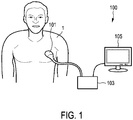
- Fig. 1 shows a schematic block diagram of an ultrasound elastography system 100 according to an embodiment, in particular a medical ultrasound imaging system.
- the ultrasound elastography system 100 comprises an ultrasound probe 101 having a plurality of transducer elements for transmitting and/or receiving ultrasound waves.
- the transducer elements can transmit ultrasound waves in form of at least one transmit pulse of a specific pulse duration (in particular a plurality of subsequent transmit pulses).
- the transducer elements can transmit ultrasound waves in form of continuous wave (CW), although that is not typically used for imaging.
- the transducer elements can for example be arranged in a (one-dimensional) row (e.g. for providing a two-dimensional image) or in a (two-dimensional) array (e.g.
- the ultrasound probe 101 may be handheld by the user of the system (e.g. medical staff or a doctor).
- the ultrasound probe 101 is applied to the body of a patient 1 for providing a strain image of an anatomical site in the patient 1.
- the ultrasound elastography system 100 further comprises a signal processing unit 103.
- the signal processing unit 103 may for example include analog or digital electronic circuits, a processor, microprocessor or the like.
- the signal processing unit 103 is connected to the ultrasound probe 101.
- the signal processing unit 103 is configured to receive a time varying ultrasound signal from the ultrasound probe 101, in particular from the transducer elements receiving the ultrasound waves.
- time-varying means that the ultrasound signal is received over time. More particularly, an echo from a single transmit pulse is spread over time corresponding to progressively deeper depths, and echoes (ultrasound echo signal) are received from multiple transmit pulses.
- the signal processing unit 103 is configured to determine axial motion data based on the time-varying ultrasound signal.
- the axial motion data indicates a relative axial motion between the ultrasound probe 101 (or its transducer elements) and the anatomical site in an axial direction.
- relative axial motion can be determined by comparing the ultrasound echo signals at the same anatomical site (or spatial location) from at least two different transmit pulses (at two different points of time).
- the axial direction is usually the depth direction (aligned with the centerline of the ultrasound probe), for example orthogonal to the skin of the patient 1 when the ultrasound probe 101 is externally applied to the skin.
- the axial direction is the direction in which the ultrasound transducer elements transmit the ultrasound waves.
- the ultrasound waves or beams can be steered at an angle with respect to the depth direction or centerline of the ultrasound probe (e.g. using a beam former).
- the transducer elements may be arranged in a curve so as to transmit ultrasound waves at various angles with respect to the depth direction or centerline of the ultrasound probe.
- lateral direction can be understood to mean across the strain image (across the set of axial ultrasound lines).
- Relative axial motion can be regarded as relative axial displacement between the ultrasound probe and the anatomical site, from the ultrasound echo signal from one transmit pulse to the corresponding ultrasound echo signal from another transmit pulse in the same direction(e.g. echoes at two different points of time).
- the relative axial motion results from some relative axial compression (or decompression) between the ultrasound probe and the anatomical site.
- the compression can be provided by the weight of the ultrasound probe 1 and/or by physical pressure applied by the user of the system.
- the signal processing unit 103 can be configured to determine strain image data based on the axial motion data. Strain image data can in particular be determined by determining the axial derivative of the axial motion data. Thus, strain can be regarded as the axial derivative of axial motion. This can be an incremental strain over each of a plurality of short image time intervals. Alternatively, these incremental strains could also be accumulated to yield a total strain.
- the ultrasound elastography system 100 further comprises a display 105.
- the display 105 is connected to the signal processing unit 103 for receiving image data from the signal processing unit 103.
- the display 105 is configured to display a strain image of the anatomical site based on the determined strain image data.
- Fig. 2 shows an exemplary image displayed by a display of an ultrasound elastography system according to an embodiment.
- the image can in particular be displayed by the display 105 of the ultrasound system 100 as explained with reference to Fig. 1 .
- the displayed image comprises a two-dimensional ultrasound echo intensity image 230 of the anatomical site.
- the echo intensity image of Fig. 2 is a two-dimensional gray scale image.
- the ultrasound echo intensity image 230 can be displayed based on echo intensity data which is determined based on the ultrasound signal.
- the signal processing unit 103 can further be configured to determine echo intensity data based on the ultrasound signal.
- one echo intensity image 230 is displayed on the left side.
- the same echo intensity image 230 is displayed on the right side, but additionally a strain image 200 is overlaid on the strain image 230.
- the strain image 200 is overlaid on the echo intensity image 230 in form of a window.
- the strain image 200 can be displayed using a color scale, thus a variety of colors (e.g. a color spectrum ranging from blue to red).
- a legend 210 can indicate the color range.
- the color blue on the bottom of the legend 210 can indicate hard tissue (abbreviated by HD in Fig. 2 ) and the color red on the top of the legend 210 can indicate soft tissue (abbreviated by SF in Fig. 2 ).
- the strain image 200 can be displayed using a gray scale.
- the signal processing unit 103 is further configured to determine a lateral variation of the axial motion in a lateral direction based on the axial motion data
- the display unit 105 is further configured to display an indication of lateral variation of a quality of the strain image 200 based on the lateral variation of the axial motion.
- the lateral direction is usually orthogonal to the axial direction.
- axial direction e.g. steering of ultrasound waves at an angle or arrangement of transducer elements in a curve
- lateral direction can in general mean across the strain image (across the set of axial ultrasound lines).
- the indication of strain image quality is a bar graph 220 having a bar 222.
- the indication of the lateral variation in form of the bar graph 222 is displayed in the vicinity of the strain image 200 (in Fig. 2 right of the strain image 200).
- the indication of the lateral variation of the strain image quality can be displayed in real time.
- the indication of the lateral variation of the strain image quality can be stored in a memory for later displaying. The later displaying or reviewing can be performed on the ultrasound system 100 itself or on some other review system.
- Fig. 2a shows an enlarged view of a portion of the image of Fig. 2 .
- the portion of the image shown in Fig. 2a is the strain image 200 of Fig. 2 .
- the y-axis of the strain image 200 indicates the axial direction and the x-axis of the strain image 200 indicates the lateral direction x.
- the axial motion data is two-dimensional data for a plurality of points P(x i , y i ) each having an axial position y i and a lateral position x i .
- the axial motion data indicates an amount of relative axial motion for each point P(x i , y i ) of the plurality of points.
- the lateral variation of the axial motion can be determined by determining for at least two lateral positions x i in the lateral direction x, an amount of relative axial motion and by comparing these amounts of axial motion. For example, a first amount of axial motion can be determined for a first lateral position x 1 and a second amount of axial motion can be determined for a second lateral position x 2 . The first amount of axial motion and the second amount of axial motion can then be compared to determine the lateral variation.
- the display unit 105 can be configured to display the indication of the lateral variation of the strain image quality by displaying an indication of the amount of axial motion as a function of the lateral position x i . This will be further explained in the following.
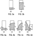
- Fig. 3a and Fig. 3b each shows an exemplary bar graph 220 of the ultrasound elastography system 100, when no lateral variation of axial motion is present.
- Fig. 3a and Fig. 3b different degrees of average compression were applied.
- the shape of the bar 222 is rectangular, like a conventional bar graph.
- the heights h 1 , h 2 of the bar 222 indicates a level of strain image quality.
- the color of the bar 222 can indicate the level of strain image quality (e.g. gray providing a low quality and green providing a high quality).
- the height h 1 of the bar 222 in Fig. 3a is smaller than the height h 2 of the bar 222 in Fig. 3b .
- the smaller height h 1 in Fig. 3a may indicate that the strain image quality level in Fig. 3a is lower than in Fig. 3b .
- a better quality strain image 200 would be provided compared to Fig. 3a .
- Fig. 4a to Fig. 4d each shows an exemplary bar graph 220 of the ultrasound elastography system 100, when lateral variation of axial motion is present.
- Fig. 3a and Fig. 3b various different degrees of average compression and tilting/rocking were applied.
- lateral variation of the axial motion is present.
- the shape of the bar 222 indicates the lateral variation of the strain image quality.
- the top side of the bar 222 indicates the lateral variation.
- the shape of the bar 222 in particular its top side, is slanted and curved as the strain image quality laterally varies.
- the shape of the bar 222 has at least two different heights h 1 , h 2 at one point of time.
- the shape of the bar 222 decreases from a first lateral position x 1 having a first height h 1 to a second lateral position x 2 having a second height h 2 smaller than the first height h 1 .
- the shape of the bar 222 increases from a first lateral position x 1 having a first height h 1 to a second lateral position x 2 having a second height h 2 bigger than the first height h 1 .
- Fig. 4a the shape of the bar 222 decreases from a first lateral position x 1 having a first height h 1 to a second lateral position x 2 having a second height h 2 smaller than the first height h 1 .
- the shape of the bar 222 increases from a first lateral position x 1 having a first height h 1 to a second lateral position x 2 having a second height h 2 bigger than the first height
- the shape of the bar 222 also increases from a first lateral position x 1 having a first height h 1 to a second lateral position x 2 having a second height h 2 bigger than the first height h 1 .
- the shape of the bar 222 increases steeper.
- the difference between the first height h 1 and the second height h 2 is bigger as compared to Fig. 4b .
- the shape of the bar 222 is V-shaped.
- the shape of bar 222 decreases from a first lateral position x 1 having a first height h 1 to a medium lateral position x M (in between the first lateral position x 1 and the second lateral position x 2 ) having a medium height h M , and increases from the medium lateral position x M to a second lateral position x 2 having a height h 2 bigger than the height h M .
- the V-shape indicates that the axial motion changes direction in the lateral direction x with an intermediate lateral position x M having very little (e.g. close to zero) axial motion. This intermediate lateral position x M or region having nearly zero axial motion indicates or has poor or low strain image quality.
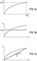
- Fig. 5a to Fig. 5c each shows an exemplary diagram of axial motion.
- a specific lateral position x i an amount of relative axial motion m as a function of axial position y i is depicted.
- axial motion m is a roughly monotonic function of axial position y i or depth.
- a maximum amount m max of the amounts of relative axial motion m of the points of the plurality of points which have the respective lateral position x i is determined.
- the axial motion data indicates the maximum amount m max of relative axial motion for each point P(x i , y i ) of two-dimensional data as explained with reference to Fig. 2a .
- the maximum amount m max of axial motion as a function of lateral position x i is provided, which thus shows the lateral variation of axial motion.
- the amount of axial motion of the points of the plurality of points which have the respective lateral position x i are averaged. This yields an average amount m aver of relative axial motion.
- the axial motion data indicates the average amount m aver of relative axial motion for each point P(x i , y i ) of two-dimensional data as explained with reference to Fig. 2a .
- the average axial motion m aver as a function of lateral position x i is provided, which thus shows the lateral variation of axial motion.
- the slope or derivative ⁇ m/ ⁇ y of the axial motion m indicates the strain.
- the axial derivatives ⁇ m/ ⁇ y of the amounts of axial motion (thus the strains) of the points of the plurality of point which have the respective lateral position x i are averaged. This yields an average axial derivative m' aver , thus average strain.
- the axial motion data indicates the average strain for each point P(x i , y i ) of two-dimensional data as explained with reference to Fig. 2a .
- This averaging can for example be performed before the strain is normalized (auto-scaled) in the strain image data for displaying the strain image.
- the average strains (derivatives of axial motion amounts) as a function of lateral position x i is provided, which thus shows the lateral variation of axial motion.
- Fig. 6a-6c show three different examples of ultrasound probe motion and a corresponding bar graph 220.
- the ultrasound probe 101 is placed on a surface of a body, here skin 2 of a patient 1.
- the axial motion between the ultrasound probe 101 and the anatomical site of the patient 1 is indicated by arrows in the depth direction (y-direction).
- the motion indicated in Fig. 6a-c is exaggerated for illustration purposes. It should be noted that in reality the motion is in general extremely small compared to the size of the ultrasound probe 101, so that the change in the position or angle of the ultrasound probe 101 may not be noticeable by the user (e.g. using sight or touch).
- Fig. 6a-6c show three different examples of ultrasound probe motion and a corresponding bar graph 220.
- the ultrasound probe 101 is placed on a surface of a body, here skin 2 of a patient 1.
- the axial motion between the ultrasound probe 101 and the anatomical site of the patient 1 is indicated by arrows in the depth direction (y-direction).
- lateral variation of axial motion is not present and thus motion is purely axial motion.
- the heights of the arrows are constant in the lateral direction (x-direction).
- the corresponding bar graph 220 has a rectangular shape of the bar 222 is rectangular, like a conventional bar graph (horizontal top side of bar 222).
- lateral variation of axial motion e.g. rocking and/or tilting
- the height arrows indicating axial motion are not constant, but varying in the lateral direction (x-direction).
- the corresponding bar graph 220 has a bar 222 which shape indicates the lateral variation of the strain image quality (slanted top side of bar 222).
- a bar 222 which shape indicates the lateral variation of the strain image quality (slanted top side of bar 222).
- even more lateral variation e.g. rocking and/or tilting
- the axial motion changes direction in the lateral direction x (laterally across the image), with an intermediate point x M or region having nearly zero axial motion.
- the corresponding bar graph 220 has a V-shaped bar 222.
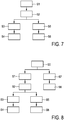
- Fig. 7 shows a schematic block diagram of an ultrasound elastography method according to an embodiment.
- a time-varying ultrasound signal is received from an ultrasound probe having at least one transducer element.
- the ultrasound probe can in particular be the ultrasound probe 101 as explained with reference to the embodiment of Fig. 1 .
- axial motion data based on the time-varying ultrasound signal is determined.
- the axial motion data indicates a relative axial motion between the ultrasound probe and the anatomical site in an axial direction y.
- a lateral variation of the axial motion in a lateral direction x based on the actual motion data is determined.
- strain image data based on the axial motion data is determined.
- step S6 a strain image 200 of the anatomical site is displayed based on the strain image data. Further, in step S4 an indication of lateral variation of a quality of the strain image based on the lateral variation of the axial motion is displayed. These displaying steps can for example be performed by a display 105 as explained with reference to the embodiment of Fig. 1 .
- Fig. 8 shows a schematic block diagram of an ultrasound elastography method according to a variant of the embodiment of Fig. 7 .
- the variant of Fig. 8 differs from the embodiment of Fig. 8 in an additional step S7 of determining ultrasound echo intensity data based on the ultrasound signal, and a step S8 of displaying an ultrasound echo intensity image of the anatomical site.
- the ultrasound echo intensity data and the strain data can be based on the ultrasound echo signal from the same transmit pulse (set of transmit pulses) or from different transmit pulses (sets of transmit pulses).
- axial motion data being two-dimensional data for a plurality of points P(x i , y i ), each having an axial position y i and a lateral position x i .
- the axial motion data can also be three-dimensional data for a plurality of points P(x i , y i , z i ), each having an axial position y i , a lateral position x i and an elevational position z i .
- the signal processing unit 103 can then be configured to determine an elevational variation of the axial motion in an elevation direction z based on the axial motion data, and the display unit 105 can be configured to display an indication of elevational variation of strain image quality based on the elevational variation of the axial motion.
- the elevational direction z is orthogonal to each of the axial direction y and the lateral direction x. Further, the display unit can be configured to display a three-dimensional strain image or multi-planar strain image.
- a computer program may be stored/distributed on a suitable medium, such as an optical storage medium or a solid-state medium supplied together with or as part of other hardware, but may also be distributed in other forms, such as via the Internet or other wired or wireless telecommunication systems.
- a suitable medium such as an optical storage medium or a solid-state medium supplied together with or as part of other hardware, but may also be distributed in other forms, such as via the Internet or other wired or wireless telecommunication systems.
Description
- The present invention relates to an ultrasound elastography system and method for providing a strain image of an anatomical site (e.g. an anatomical site of a patient). The present invention further relates to a computer program for implementing such method.
- In ultrasound strain elastography an image of relative axial strain, which is associated with tissue stiffness differences, is displayed. This strain image (also called elastogram), can for example help to distinguish lesion malignancy. An estimation of axial strain requires some axial compression (or de-compression) in the form of a relative axial motion between transducer element(s) of an ultrasound probe and the anatomical site (e.g. a patient's (deeper) tissues). Such compression can be provided by the weight of the ultrasound probe and/or by physical pressure applied by the user of the system (e.g. medical staff or a doctor) and/or by internal patient motion due to heartbeat or breathing. A sensitive elastography system can require very little motion (e.g. a relative axial motion in the order of 10 µm). More compression can tend to improve the strain image quality, until degrading effects such as de-correlation, blurring or misregistration can become dominant (e.g. around a relative axial motion of about 1 mm). Because the required (slight) relative axial motion for ultrasound elastography may approach the limit of the user's physical perception and/or because it may affect the quality of the strain image, an elastography system can be able to display an indication of the quality of the strain image. This indication can for example be a (non-quantitative) bar graph next to the strain image.
- An exemplary elastography system displaying such bar graph is the Philips iU22 system. For example, the brochure "Sensitivity and strength, Philips Breast Elastography Ultrasound Quick Start Guide, Philips, 2010" (e.g. currently to be found at http://www.healthcare.philips.com/main/products/ultrasound/technologies/elastography.wpd) , which is a quick start guide providing a brief overview of the Philips iU22 breast elastography system, discloses that a real-time compression feedback bar is displayed next to the strain image. This on-screen indicator provides the user with real-time feedback on the appropriate amount of deformation for the elastogram. The system computes the level of resulting tissue deformation and displays it as a green and grey bar to indicate appropriate (green) and inappropriate (grey) tissue deformation for a quality elastogram.
- Further elastography imaging systems are known from
US 2010/0220901 A1 ,US 2010/0134629 A1 ,US 2010/0179413 A1 , and from Lindop, J. et al.: " Dynamic Resolution Selection in Ultrasonic Strain Imaging", Ultrasound in Medicine and Biology, New York, vol. 34, no. 5, May 2008. - There is a need to further improve such elastography system.
- It is an object of the present invention to provide an improved ultrasound elastography system and method. It is a further object of the present invention to provide a computer program for implementing such method.
- In a first aspect of the present invention an ultrasound elastography system for providing a strain image of an anatomical site is presented. The system comprises a signal processing unit configured to receive a time-varying ultrasound signal from an ultrasound probe having at least one transducer element, to determine axial motion data based on the time-varying ultrasound signal, the axial motion data indicating a relative axial motion between the ultrasound probe and the anatomical site in an axial direction, and to determine a lateral variation of the axial motion in a lateral direction based on the axial motion data. The system further comprises a display unit configured to display a strain image of the anatomical site based on strain image data which is determined based on the axial motion data, and to display an indication of lateral variation of a quality of the strain image based on the lateral variation of the axial motion, wherein the indication of strain image quality is a bar graph having a bar, wherein a shape of the bar indicates the lateral variation of the strain image quality wherein the lateral variation of the axial motion is determined by determining, for at least two lateral positions in the lateral direction, an amount of relative axial motion and by comparing the amounts of axial motion, wherein the indication of the lateral variation of the strain image quality is displayed by displaying an indication of the amount of relative axial motion as a function of the lateral position and wherein the lateral variation of the strain image quality is directly the indication of the amount of relative axial motion as a function of the lateral position.
- In a further aspect of the present invention an ultrasound elastography method for providing a strain image of an anatomical site is presented. The method comprises receiving a time-varying ultrasound signal from an ultrasound probe having at least one transducer element, determining axial motion data based on the time-varying ultrasound signal, the axial motion data indicating a relative axial motion between the ultrasound probe and the anatomical site in an axial direction, determining a lateral variation of the axial motion in a lateral direction based on the axial motion data, displaying a strain image of the anatomical site based on strain image data which is determined based on the axial motion data, and displaying an indication of lateral variation of a quality of the strain image based on the lateral variation of the axial motion, wherein the indication of strain image quality is a bar graph having a bar, wherein a shape of the bar indicates the lateral variation of the strain image quality, wherein the lateral variation of the axial motion is determined by determining, for at least two lateral positions in the lateral direction, an amount of relative axial motion and by comparing the amounts of axial motion, wherein the indication of the lateral variation of the strain image quality is displayed by displaying an indication of the amount of relative axial motion as a function of the lateral position and wherein the lateral variation of the strain image quality is directly the indication of the amount of relative axial motion as a function of the lateral position.
- In a further aspect of the present invention a computer program is presented comprising program code means for causing a computer to carry out the steps of such method when said computer program is carried out on the computer.
- The basic idea of the invention is to determine a lateral variation of axial motion and to display an indication of lateral variation of strain image quality based on this lateral variation of the axial motion. The lateral direction is orthogonal to the axial direction. In particular, the axial direction can be the depth direction (e.g. orthogonal to the skin of the patient) and/or the direction in which the transducer element(s) transmits ultrasound waves. The or each transducer element is configured to transmit and/or receive ultrasound waves. Relative axial motion can be regarded as relative axial displacement between the ultrasound probe (or transducer element(s)) and the anatomical site from one point of time to another point of time. Relative axial motion can thus be determined from a time-varying ultrasound echo signal. Each axial line of an ultrasound image can be constructed from ultrasound echo (intensity and/or phase) data resulting from echo signals received at the transducer element(s) from progressively deeper depths following each transmit pulse of at least one transmit pulse transmitted by the transducer element(s). In particular, relative axial motion can be determined by comparing the ultrasound echo signals at the same anatomical site (or spatial location) from at least two different transmit pulses (at two different points of time).
- Especially when the relative axial motion is very slight and not even deliberate, there can be as much (or even more), lateral tilting and/or rocking as there is overall axial motion. This means that the axial motion can significantly vary across the strain image area. Often this pattern of lateral tilting and/or rocking is not random, but is relatively stable over time, e.g. several seconds, because it depends on the physical arrangement of the user's body and the patient's body. By displaying the indication of lateral variation of the strain image quality the user gets an indication of the lateral variation and may adjust his or her holding and/or motion of the ultrasound probe accordingly. Thus, the user can be guided by the indication to improve the quality of the strain image.
- Preferred embodiments of the invention are defined in the dependent claims. It shall be understood that the claimed ultrasound elastography method or computer program has similar and/or identical preferred embodiments as the claimed ultrasound elastography system and as defined in the dependent claims.
- In one embodiment the lateral variation of the axial motion is determined by determining, for at least two lateral positions in the lateral direction, an amount of relative axial motion and by comparing the amounts of axial motion. In this embodiment a simple way of determining the lateral variation of the axial motion is provided.
- According to the invention the display unit is configured to display the indication of the lateral variation of the strain image quality by displaying an indication of the amount of relative axial motion as a function of the lateral position. Accordingly, the indication of the lateral variation of the strain image quality is directly an indication of the amount of relative axial motion as a function of the lateral position.
- In another embodiment the axial motion data is two-dimensional data for a plurality of points each having an axial position and a lateral position, the axial motion data indicating an amount of axial motion for each point of the plurality of points. In this embodiment a two-dimensional strain image can be displayed.
- In a variant of this embodiment determining the lateral variation of the axial motion comprises averaging, for each of at least two lateral positions in the lateral direction, the amounts of relative axial motion of the points of the plurality of points which have the respective lateral position. In this variant the axial motion amounts are averaged. Thus, average axial motion as a function of lateral position is provided, which thus shows the lateral variation of axial motion.
- In an alternative variant of this embodiment determining the lateral variation of the axial motion comprises averaging, for each of at least two lateral positions in the lateral direction, the axial derivatives of the amounts of relative axial motion of the points of the plurality of points which have the respective lateral position. In this variant the strains (derivatives of axial motion amounts) are averaged. Thus, average strain as a function of lateral position is provided which thus shows the lateral variation of axial motion.
- In a further embodiment the indication of strain image quality is a bar graph having a bar. In this embodiment a simple implementation of the stain image quality indication is provided. The indication in form of the bar graph does not need to occupy any additional space on the display compared to a conventional bar graph. It can still be a non-quantitave indication. It can be intuitive enough that very little user training or practice is needed.
- In a variant of this embodiment a height of the bar indicates a level of strain image quality. In particular, the height of the bar can indicate the amount of axial motion. In this variant the user can easily be guided by simply watching the height of the bar.
- In a further variant a shape of the bar indicates the lateral variation of the strain image quality. In this embodiment an advantageous implementation of an indication of lateral variation of strain image quality is provided. For example, if there is no lateral variation of axial motion (thus the motion is purely axial), the shape of the bar can be rectangular, like a conventional bar graph. If there is lateral variation of the axial motion present, the shape of the bar can change. For example, at least one side (e.g. the top side) of the bar can change. In this way lateral variation can be easily perceived by the user.
- In a further variant the shape of the bar is slanted and/or curved when the strain image quality laterally varies. In particular, the shape of the bar can have at least two different heights. In this variant an advantageous implementation for the indication of the lateral variation of strain image quality is provided. If there is lateral variation of the axial motion (e.g. rocking and/or tilting), the shape of the bar (e.g. its top side) becomes slanted and/or curved. In particular, the shape of the bar may become V-shaped when the strain image quality varies. This V-shape may indicate that the lateral variation of the axial motion (e.g. rocking and/or tilting) exceeds the axial motion, so that the axial motion changes direction in the lateral direction (laterally across the image), with an intermediate region having nearly zero axial motion.
- In a further embodiment the indication of the lateral variation of the strain image quality is displayed in real-time and/or stored in a memory for later displaying. By displaying the indication in real-time, the user gets immediate feedback about the lateral variation. By storing the indication in memory, the strain image quality can be displayed or reviewed at a later point of time.
- In a further embodiment the display unit is further operable to display ultrasound echo intensity image of the anatomical site. The ultrasound echo intensity image can for example be a two-dimensional, three-dimensional or multi-planar ultrasound echo intensity image.
- In a variant of this embodiment the ultrasound echo intensity image can be displayed based on echo intensity data which is determined based on the ultrasound signal. In this embodiment the system is not only configured to display a strain image, but also to display a conventional ultrasound echo density image. In one example, the ultrasound echo intensity image and the strain image can be based on the ultrasound echo signal from the same transmit pulse or the same set of transmit pulses. In an alternative example, the ultrasound echo intensity image and the strain image can be based on the ultrasound echo signal from different transmit pulses or different sets of transmit pulses.
- In a further embodiment the signal processing unit is configured to determine an elevational variation of the axial motion in an elevation direction based on the axial motion data, and the display unit is configured to display an indication of elevational variation of strain image quality based on the elevational variation of the axial motion. In this embodiment, not only a lateral variation of the axial motion is provided, but additionally also an elevational variation of the axial motion. Thus, the variation of the axial motion in two different dimensions is provided. In general, this could be extended to more than two directions, which would then not be orthogonal to each other
- In a further embodiment, the system comprises the ultrasound probe having the at least one transducer element. In this embodiment the ultrasound probe is thus part of the system. For example, it can be (directly) connected to the signal processing unit.
- In a variant of this embodiment the ultrasound probe has a plurality of transducer elements. The plurality of transducer elements can in particular be arranged in a (one-dimensional) row or a (two-dimensional) array. In this way a two-dimensional or multi-planar or three-dimensional image can be provided.
- These and other aspects of the invention will be apparent from and elucidated with reference to the embodiment(s) described hereinafter. In the following drawings
-
Fig. 1 shows a schematic block diagram of an ultrasound elastography system according to an embodiment; -
Fig. 2 shows an exemplary image displayed on a display of an ultrasound elastography system according to an embodiment; -
Fig. 2a shows an enlarged view of a portion of the image ofFig. 2 ; -
Fig. 3a and 3b each show an exemplary bar graph of the ultrasound elastography system, when no lateral variation of axial motion is present; -
Fig. 4a-4d each shows an exemplary bar graph of the ultrasound elastography system, when lateral variation of axial motion is present; -
Fig. 5a-5c each shows an exemplary diagram of axial motion; -
Fig. 6a-6c show three different examples of ultrasound probe motion and a corresponding bar graph; -
Fig. 7 shows a schematic block diagram of an ultrasound elastography method according to an embodiment; and -
Fig. 8 shows a schematic block diagram of an ultrasound elastography method according to a variant of the embodiment ofFig. 7 . -
Fig. 1 shows a schematic block diagram of anultrasound elastography system 100 according to an embodiment, in particular a medical ultrasound imaging system. Theultrasound elastography system 100 comprises anultrasound probe 101 having a plurality of transducer elements for transmitting and/or receiving ultrasound waves. In one example, the transducer elements can transmit ultrasound waves in form of at least one transmit pulse of a specific pulse duration (in particular a plurality of subsequent transmit pulses). In an alternative example, the transducer elements can transmit ultrasound waves in form of continuous wave (CW), although that is not typically used for imaging. The transducer elements can for example be arranged in a (one-dimensional) row (e.g. for providing a two-dimensional image) or in a (two-dimensional) array (e.g. for providing a multi-planar or three-dimensional image). Theultrasound probe 101 may be handheld by the user of the system (e.g. medical staff or a doctor). Theultrasound probe 101 is applied to the body of apatient 1 for providing a strain image of an anatomical site in thepatient 1. - The
ultrasound elastography system 100 further comprises asignal processing unit 103. Thesignal processing unit 103 may for example include analog or digital electronic circuits, a processor, microprocessor or the like. Thesignal processing unit 103 is connected to theultrasound probe 101. Thesignal processing unit 103 is configured to receive a time varying ultrasound signal from theultrasound probe 101, in particular from the transducer elements receiving the ultrasound waves. In this context time-varying means that the ultrasound signal is received over time. More particularly, an echo from a single transmit pulse is spread over time corresponding to progressively deeper depths, and echoes (ultrasound echo signal) are received from multiple transmit pulses. Thesignal processing unit 103 is configured to determine axial motion data based on the time-varying ultrasound signal. The axial motion data indicates a relative axial motion between the ultrasound probe 101 (or its transducer elements) and the anatomical site in an axial direction. In particular, relative axial motion can be determined by comparing the ultrasound echo signals at the same anatomical site (or spatial location) from at least two different transmit pulses (at two different points of time). For strain elastography, the axial direction is usually the depth direction (aligned with the centerline of the ultrasound probe), for example orthogonal to the skin of thepatient 1 when theultrasound probe 101 is externally applied to the skin. In general, the axial direction is the direction in which the ultrasound transducer elements transmit the ultrasound waves. Alternatively, the ultrasound waves or beams can be steered at an angle with respect to the depth direction or centerline of the ultrasound probe (e.g. using a beam former). Further alternatively, the transducer elements may be arranged in a curve so as to transmit ultrasound waves at various angles with respect to the depth direction or centerline of the ultrasound probe. For these more generalized cases of axial direction, lateral direction can be understood to mean across the strain image (across the set of axial ultrasound lines). - Relative axial motion can be regarded as relative axial displacement between the ultrasound probe and the anatomical site, from the ultrasound echo signal from one transmit pulse to the corresponding ultrasound echo signal from another transmit pulse in the same direction(e.g. echoes at two different points of time). The relative axial motion results from some relative axial compression (or decompression) between the ultrasound probe and the anatomical site. The compression can be provided by the weight of the
ultrasound probe 1 and/or by physical pressure applied by the user of the system. Thesignal processing unit 103 can be configured to determine strain image data based on the axial motion data. Strain image data can in particular be determined by determining the axial derivative of the axial motion data. Thus, strain can be regarded as the axial derivative of axial motion. This can be an incremental strain over each of a plurality of short image time intervals. Alternatively, these incremental strains could also be accumulated to yield a total strain. - The
ultrasound elastography system 100 further comprises adisplay 105. Thedisplay 105 is connected to thesignal processing unit 103 for receiving image data from thesignal processing unit 103. Thedisplay 105 is configured to display a strain image of the anatomical site based on the determined strain image data. -
Fig. 2 shows an exemplary image displayed by a display of an ultrasound elastography system according to an embodiment. The image can in particular be displayed by thedisplay 105 of theultrasound system 100 as explained with reference toFig. 1 . The displayed image comprises a two-dimensional ultrasoundecho intensity image 230 of the anatomical site. The echo intensity image ofFig. 2 is a two-dimensional gray scale image. The ultrasoundecho intensity image 230 can be displayed based on echo intensity data which is determined based on the ultrasound signal. Thus, thesignal processing unit 103 can further be configured to determine echo intensity data based on the ultrasound signal. In the image ofFig. 2 oneecho intensity image 230 is displayed on the left side. The sameecho intensity image 230 is displayed on the right side, but additionally astrain image 200 is overlaid on thestrain image 230. Thestrain image 200 is overlaid on theecho intensity image 230 in form of a window. Thestrain image 200 can be displayed using a color scale, thus a variety of colors (e.g. a color spectrum ranging from blue to red). Alegend 210 can indicate the color range. Just as an example, the color blue on the bottom of thelegend 210 can indicate hard tissue (abbreviated by HD inFig. 2 ) and the color red on the top of thelegend 210 can indicate soft tissue (abbreviated by SF inFig. 2 ). Alternatively, thestrain image 200 can be displayed using a gray scale. - The
signal processing unit 103 is further configured to determine a lateral variation of the axial motion in a lateral direction based on the axial motion data, and thedisplay unit 105 is further configured to display an indication of lateral variation of a quality of thestrain image 200 based on the lateral variation of the axial motion. For strain elastography, the lateral direction is usually orthogonal to the axial direction. However, as mentioned above, for more generalized cases of axial direction (e.g. steering of ultrasound waves at an angle or arrangement of transducer elements in a curve), lateral direction can in general mean across the strain image (across the set of axial ultrasound lines). - By displaying the indication of lateral variation of the strain image quality, the user (e.g. medical staff or a doctor) gets an indication of the lateral variation and may adjust his or her holding of the
ultrasound probe 101 accordingly. Thus, the user can be guided by the indication to improve the strain image quality. Alternatively or cumulatively, a later reviewer can interpret the strain image accordingly. In the embodiment ofFig. 2 , the indication of strain image quality is abar graph 220 having abar 222. The indication of the lateral variation in form of thebar graph 222 is displayed in the vicinity of the strain image 200 (inFig. 2 right of the strain image 200). The indication of the lateral variation of the strain image quality can be displayed in real time. Alternatively, the indication of the lateral variation of the strain image quality can be stored in a memory for later displaying. The later displaying or reviewing can be performed on theultrasound system 100 itself or on some other review system. -
Fig. 2a shows an enlarged view of a portion of the image ofFig. 2 . The portion of the image shown inFig. 2a is thestrain image 200 ofFig. 2 . The y-axis of thestrain image 200 indicates the axial direction and the x-axis of thestrain image 200 indicates the lateral direction x. In this case, the axial motion data is two-dimensional data for a plurality of points P(xi, yi) each having an axial position yi and a lateral position xi. The axial motion data indicates an amount of relative axial motion for each point P(xi, yi) of the plurality of points. The lateral variation of the axial motion can be determined by determining for at least two lateral positions xi in the lateral direction x, an amount of relative axial motion and by comparing these amounts of axial motion. For example, a first amount of axial motion can be determined for a first lateral position x1 and a second amount of axial motion can be determined for a second lateral position x2. The first amount of axial motion and the second amount of axial motion can then be compared to determine the lateral variation. Thedisplay unit 105 can be configured to display the indication of the lateral variation of the strain image quality by displaying an indication of the amount of axial motion as a function of the lateral position xi. This will be further explained in the following. -
Fig. 3a and Fig. 3b each shows anexemplary bar graph 220 of theultrasound elastography system 100, when no lateral variation of axial motion is present. For the examples ofFig. 3a and Fig. 3b different degrees of average compression were applied. In each ofFig. 3a and Fig. 3b lateral variation of axial motion is not present and thus motion is purely axial motion. In this case, the shape of thebar 222 is rectangular, like a conventional bar graph. The heights h1, h2 of thebar 222 indicates a level of strain image quality. Additionally or alternatively, the color of thebar 222 can indicate the level of strain image quality (e.g. gray providing a low quality and green providing a high quality). The height h1 of thebar 222 inFig. 3a is smaller than the height h2 of thebar 222 inFig. 3b . The smaller height h1 inFig. 3a may indicate that the strain image quality level inFig. 3a is lower than inFig. 3b . Thus, inFig. 3b a betterquality strain image 200 would be provided compared toFig. 3a . -
Fig. 4a to Fig. 4d each shows anexemplary bar graph 220 of theultrasound elastography system 100, when lateral variation of axial motion is present. For the examples ofFig. 3a and Fig. 3b various different degrees of average compression and tilting/rocking were applied. In each ofFig. 4a to Fig. 4d lateral variation of the axial motion is present. In this case, the shape of thebar 222 indicates the lateral variation of the strain image quality. In particular, the top side of thebar 222 indicates the lateral variation. In each ofFig. 4a to Fig. 4d the shape of thebar 222, in particular its top side, is slanted and curved as the strain image quality laterally varies. The shape of thebar 222 has at least two different heights h1, h2 at one point of time. InFig. 4a the shape of thebar 222 decreases from a first lateral position x1 having a first height h1 to a second lateral position x2 having a second height h2 smaller than the first height h1. InFig. 4b the shape of thebar 222 increases from a first lateral position x1 having a first height h1 to a second lateral position x2 having a second height h2 bigger than the first height h1. InFig. 4c the shape of thebar 222 also increases from a first lateral position x1 having a first height h1 to a second lateral position x2 having a second height h2 bigger than the first height h1. Compared toFig. 4b , inFig. 4c the shape of thebar 222 increases steeper. Thus, inFig. 4c the difference between the first height h1 and the second height h2 is bigger as compared toFig. 4b . InFig. 4d the shape of thebar 222 is V-shaped. Thus, the shape ofbar 222 decreases from a first lateral position x1 having a first height h1 to a medium lateral position xM (in between the first lateral position x1 and the second lateral position x2) having a medium height hM, and increases from the medium lateral position xM to a second lateral position x2 having a height h2 bigger than the height hM. The V-shape indicates that the axial motion changes direction in the lateral direction x with an intermediate lateral position xM having very little (e.g. close to zero) axial motion. This intermediate lateral position xM or region having nearly zero axial motion indicates or has poor or low strain image quality. -
Fig. 5a to Fig. 5c each shows an exemplary diagram of axial motion. In each ofFig. 5a to Fig. 5c , for a specific lateral position xi, an amount of relative axial motion m as a function of axial position yi is depicted. As can be seen in each ofFig. 5a to Fig. 5c axial motion m is a roughly monotonic function of axial position yi or depth. - In the first example of
Fig. 5a a maximum amount mmax of the amounts of relative axial motion m of the points of the plurality of points which have the respective lateral position xi is determined. In this case the axial motion data indicates the maximum amount mmax of relative axial motion for each point P(xi, yi) of two-dimensional data as explained with reference toFig. 2a . In this example the maximum amount mmax of axial motion as a function of lateral position xi is provided, which thus shows the lateral variation of axial motion. - In the second example of
Fig. 5b the amount of axial motion of the points of the plurality of points which have the respective lateral position xi are averaged. This yields an average amount maver of relative axial motion. In this case the axial motion data indicates the average amount maver of relative axial motion for each point P(xi, yi) of two-dimensional data as explained with reference toFig. 2a . In this example the average axial motion maver as a function of lateral position xi is provided, which thus shows the lateral variation of axial motion. - In the third example of
Fig. 5c , the slope or derivative Δm/Δy of the axial motion m indicates the strain. InFig. 5c , the axial derivatives Δm/Δy of the amounts of axial motion (thus the strains) of the points of the plurality of point which have the respective lateral position xi are averaged. This yields an average axial derivative m'aver, thus average strain. In this case the axial motion data indicates the average strain for each point P(xi, yi) of two-dimensional data as explained with reference toFig. 2a . This averaging can for example be performed before the strain is normalized (auto-scaled) in the strain image data for displaying the strain image. In this example the average strains (derivatives of axial motion amounts) as a function of lateral position xi is provided, which thus shows the lateral variation of axial motion. -
Fig. 6a-6c show three different examples of ultrasound probe motion and acorresponding bar graph 220. Theultrasound probe 101 is placed on a surface of a body, hereskin 2 of apatient 1. In each ofFig. 6a-c the axial motion between theultrasound probe 101 and the anatomical site of thepatient 1 is indicated by arrows in the depth direction (y-direction). The motion indicated inFig. 6a-c is exaggerated for illustration purposes. It should be noted that in reality the motion is in general extremely small compared to the size of theultrasound probe 101, so that the change in the position or angle of theultrasound probe 101 may not be noticeable by the user (e.g. using sight or touch). In the example ofFig. 6a lateral variation of axial motion is not present and thus motion is purely axial motion. The heights of the arrows (indicating the axial motion) are constant in the lateral direction (x-direction). In this case, the correspondingbar graph 220 has a rectangular shape of thebar 222 is rectangular, like a conventional bar graph (horizontal top side of bar 222). In the example ofFig. 6b lateral variation of axial motion (e.g. rocking and/or tilting) is present and thus there is a mixture of axial motion and lateral variation (e.g. rocking and/or tilting). The height arrows indicating axial motion are not constant, but varying in the lateral direction (x-direction). In this case, the correspondingbar graph 220 has abar 222 which shape indicates the lateral variation of the strain image quality (slanted top side of bar 222). In the example ofFig. 6c , compared to the example ofFig. 6b , even more lateral variation (e.g. rocking and/or tilting) is present, such that the lateral variation of axial motion exceeds the axial motion. In this case, as indicated by the arrows inFig. 6c , the axial motion changes direction in the lateral direction x (laterally across the image), with an intermediate point xM or region having nearly zero axial motion. In this case, the correspondingbar graph 220 has a V-shapedbar 222. -
Fig. 7 shows a schematic block diagram of an ultrasound elastography method according to an embodiment. In a first step S1 a time-varying ultrasound signal is received from an ultrasound probe having at least one transducer element. The ultrasound probe can in particular be theultrasound probe 101 as explained with reference to the embodiment ofFig. 1 . In a further step S2 axial motion data based on the time-varying ultrasound signal is determined. The axial motion data indicates a relative axial motion between the ultrasound probe and the anatomical site in an axial direction y. In a further step S3 a lateral variation of the axial motion in a lateral direction x based on the actual motion data is determined. Further, in step S5 strain image data based on the axial motion data is determined. These determinations can for example be performed by asignal processing unit 103 as explained with reference to the embodiment ofFig. 1 . In step S6 astrain image 200 of the anatomical site is displayed based on the strain image data. Further, in step S4 an indication of lateral variation of a quality of the strain image based on the lateral variation of the axial motion is displayed. These displaying steps can for example be performed by adisplay 105 as explained with reference to the embodiment ofFig. 1 . -
Fig. 8 shows a schematic block diagram of an ultrasound elastography method according to a variant of the embodiment ofFig. 7 . The variant ofFig. 8 differs from the embodiment ofFig. 8 in an additional step S7 of determining ultrasound echo intensity data based on the ultrasound signal, and a step S8 of displaying an ultrasound echo intensity image of the anatomical site. The ultrasound echo intensity data and the strain data can be based on the ultrasound echo signal from the same transmit pulse (set of transmit pulses) or from different transmit pulses (sets of transmit pulses). - The explanation above has been made in connection with axial motion data being two-dimensional data for a plurality of points P(xi, yi), each having an axial position yi and a lateral position xi. However, it will be understood that the axial motion data can also be three-dimensional data for a plurality of points P(xi, yi, zi), each having an axial position yi, a lateral position xi and an elevational position zi. The
signal processing unit 103 can then be configured to determine an elevational variation of the axial motion in an elevation direction z based on the axial motion data, and thedisplay unit 105 can be configured to display an indication of elevational variation of strain image quality based on the elevational variation of the axial motion. The elevational direction z is orthogonal to each of the axial direction y and the lateral direction x. Further, the display unit can be configured to display a three-dimensional strain image or multi-planar strain image. - While the invention has been illustrated and described in detail in the drawings and foregoing description, such illustration and description are to be considered illustrative or exemplary and not restrictive; the invention is not limited to the disclosed embodiments. Other variations to the disclosed embodiments can be understood and effected by those skilled in the art in practicing the claimed invention, from a study of the appended claims.
- In the claims, the word "comprising" does not exclude other elements or steps, and the indefinite article "a" or "an" does not exclude a plurality. A single element or other unit may fulfill the functions of several items recited in the claims. The mere fact that certain measures are recited in mutually different dependent claims does not indicate that a combination of these measures cannot be used to advantage.
- A computer program may be stored/distributed on a suitable medium, such as an optical storage medium or a solid-state medium supplied together with or as part of other hardware, but may also be distributed in other forms, such as via the Internet or other wired or wireless telecommunication systems.
- Any reference signs in the claims should not be construed as limiting the scope.
Claims (11)
- An ultrasound elastography system (100) for providing a strain image of an anatomical site, the system comprising a signal processing unit (103) configured to:- receive a time-varying ultrasound signal from an ultrasound probe (101) having at least one transducer element,- determine axial motion data based on the time-varying ultrasound signal, the axial motion data indicating a relative axial motion between the ultrasound probe and the anatomical site in an axial direction (y), and- determine a lateral variation of the axial motion in a lateral direction (x) based on the axial motion data; andthe system further comprising a display unit (105) configured to:- display a strain image (200) of the anatomical site based on strain image data which is determined based on the axial motion data, and- display an indication of lateral variation of a quality of the strain image based on the lateral variation of the axial motion,characterized in that the indication of strain image quality is a bar graph (220) having a bar (222), wherein a shape of the bar (222) indicates the lateral variation of the strain image quality, wherein the lateral variation of the axial motion is determined by determining, for at least two lateral positions (xi) in the lateral direction (x), an amount of relative axial motion and by comparing the amounts of axial motion,
wherein the display unit (105) is configured to display the indication of the lateral variation of the strain image quality by displaying an indication of the amount of relative axial motion as a function of the lateral position (xi) and wherein the lateral variation of the strain image quality is directly the indication of the amount of relative axial motion as a function of the lateral position. - The system of claim 1, wherein the axial motion data is two-dimensional data for a plurality of points (P(xi,yi)) each having an axial position (yi) and a lateral position (xi), the axial motion data indicating an amount of relative axial motion for each point (P(xi,yi)) of the plurality of points.
- The system of claim 2, wherein the system is configured to determine the lateral variation of the axial motion by averaging, for each of at least two lateral positions (xi) in the lateral direction (x), the amounts of relative axial motion of the points of the plurality of points which have the respective lateral position (xi).
- The system of claim 2, wherein the system is configured to determine the lateral variation of the axial motion by averaging, for each of at least two lateral positions (xi) in the lateral direction (x), the axial derivatives of the amounts of relative axial motion of the points of the plurality of points which have the respective lateral position (xi).
- The system of claim 1, wherein a height (h) of the bar (222) indicates a level of strain image quality.
- The system of claim 1, wherein the shape of the bar (222) is slanted and/or curved when the strain image quality laterally varies.
- The system of claim 1, wherein the indication of the lateral variation of the strain image quality is displayed in real-time and/or stored in a memory for later displaying.
- The system of claim 1, the display unit (105) further operable to display an ultrasound echo intensity image (230) of the anatomical site.
- The system of claim 1, wherein the signal processing unit (103) is configured to determine an elevational variation of the axial motion in an elevation direction (z) based on the axial motion data, and the display unit is configured to display an indication of elevational variation of strain image quality based on the elevational variation of the axial motion.
- A computer implemented ultrasound elastography method for providing a strain image of an anatomical site, the method comprising:- receiving (S1) a time-varying ultrasound signal from an ultrasound probe (101) having at least one transducer element,- determining (S2) axial motion data based on the time-varying ultrasound signal, the axial motion data indicating a relative axial motion between the ultrasound probe and the anatomical site in an axial direction (y),- determining (S3) a lateral variation of the axial motion in a lateral direction (x) based on the axial motion data,- displaying (S6) a strain image (200) of the anatomical site based on strain image data which is determined based on the axial motion data, and- displaying (S4) an indication of lateral variation of a quality of the strain image based on the lateral variation of the axial motion,characterized in that the indication of strain image quality is a bar graph (220) having a bar (222), wherein a shape of the bar (222) indicates the lateral variation of the strain image quality quality, wherein the lateral variation of the axial motion is determined by determining, for at least two lateral positions (xi) in the lateral direction (x), an amount of relative axial motion and by comparing the amounts of axial motion,
wherein the indication of the lateral variation of the strain image quality is displayed by displaying an indication of the amount of relative axial motion as a function of the lateral position (xi) and wherein the lateral variation of the strain image quality is directly the indication of the amount of relative axial motion as a function of the lateral position. - A computer program comprising program code means for causing a computer to carry out the steps of the method as claimed in claim 10 when said computer program is carried out on the signal processing unit comprised in the ultrasound elastography system of claim 1.
Applications Claiming Priority (2)
| Application Number | Priority Date | Filing Date | Title |
|---|---|---|---|
| US201161539599P | 2011-09-27 | 2011-09-27 | |
| PCT/IB2012/055015 WO2013050899A1 (en) | 2011-09-27 | 2012-09-21 | Ultrasound elastography system and method |
Publications (2)
| Publication Number | Publication Date |
|---|---|
| EP2744414A1 EP2744414A1 (en) | 2014-06-25 |
| EP2744414B1 true EP2744414B1 (en) | 2019-11-06 |
Family
ID=47143216
Family Applications (1)
| Application Number | Title | Priority Date | Filing Date |
|---|---|---|---|
| EP12781451.5A Active EP2744414B1 (en) | 2011-09-27 | 2012-09-21 | Ultrasound elastography system and method |
Country Status (6)
| Country | Link |
|---|---|
| US (1) | US10695030B2 (en) |
| EP (1) | EP2744414B1 (en) |
| JP (1) | JP5993952B2 (en) |
| CN (1) | CN103857342B (en) |
| BR (1) | BR112014006975A2 (en) |
| WO (1) | WO2013050899A1 (en) |
Families Citing this family (6)
| Publication number | Priority date | Publication date | Assignee | Title |
|---|---|---|---|---|
| KR101512291B1 (en) * | 2013-05-06 | 2015-04-15 | 삼성메디슨 주식회사 | Medical imaging apparatus and method of providing medical images |
| CN105392428B (en) * | 2013-06-26 | 2019-06-04 | 皇家飞利浦有限公司 | System and method for mapping the measurement of ultrasonic shear wave elastogram |
| CN110072466B (en) * | 2016-12-15 | 2022-07-19 | 皇家飞利浦有限公司 | Prenatal ultrasound imaging |
| WO2018223294A1 (en) * | 2017-06-06 | 2018-12-13 | 深圳迈瑞生物医疗电子股份有限公司 | Method, apparatus and system for imaging in ultrasonic scanning |
| CN111760203A (en) * | 2019-04-01 | 2020-10-13 | 复旦大学附属肿瘤医院 | Liver radiotherapy target positioning technology based on ultrasonic image |
| CN113081038B (en) * | 2021-04-06 | 2024-02-13 | 无锡海斯凯尔医学技术有限公司 | Elastography method, elastography device, electronic equipment and storage medium |
Citations (1)
| Publication number | Priority date | Publication date | Assignee | Title |
|---|---|---|---|---|
| US20070167772A1 (en) * | 2005-12-09 | 2007-07-19 | Aloka Co., Ltd. | Apparatus and method for optimized search for displacement estimation in elasticity imaging |
Family Cites Families (23)
| Publication number | Priority date | Publication date | Assignee | Title |
|---|---|---|---|---|
| US5474070A (en) * | 1989-11-17 | 1995-12-12 | The Board Of Regents Of The University Of Texas System | Method and apparatus for elastographic measurement and imaging |
| US6514204B2 (en) | 2000-07-20 | 2003-02-04 | Riverside Research Institute | Methods for estimating tissue strain |
| US6558324B1 (en) * | 2000-11-22 | 2003-05-06 | Siemens Medical Solutions, Inc., Usa | System and method for strain image display |
| JP4233808B2 (en) * | 2002-06-04 | 2009-03-04 | 株式会社日立メディコ | Ultrasonic diagnostic equipment |
| US7601122B2 (en) * | 2003-04-22 | 2009-10-13 | Wisconsin Alumni Research Foundation | Ultrasonic elastography with angular compounding |
| JP4465535B2 (en) * | 2004-06-09 | 2010-05-19 | 株式会社日立メディコ | Elastic image display method and ultrasonic diagnostic apparatus |
| WO2005122907A1 (en) * | 2004-06-22 | 2005-12-29 | Hitachi Medical Corporation | Ultrasonograph and elasticity image display method |
| US7736315B2 (en) | 2004-07-30 | 2010-06-15 | Wisconsin Alumni Research Foundation | Method and apparatus providing improved ultrasonic strain measurements of soft tissue |
| CN1319492C (en) * | 2004-08-06 | 2007-06-06 | 清华大学 | Variable biological tissue displacement evaluating method |
| WO2006040967A1 (en) * | 2004-10-08 | 2006-04-20 | Hitachi Medical Corporation | Ultrasonic diagnosis device |
| US9389203B2 (en) * | 2005-06-17 | 2016-07-12 | Wisconsin Alumni Research Foundation | Automated ultrasonic elasticity image formation with quality measure |
| WO2007083745A1 (en) * | 2006-01-20 | 2007-07-26 | Hitachi Medical Corporation | Elastic image display method and elastic image display |
| JP4793726B2 (en) * | 2006-01-24 | 2011-10-12 | 独立行政法人産業技術総合研究所 | Ultrasonic diagnostic equipment |
| GB0708358D0 (en) * | 2007-05-01 | 2007-06-06 | Cambridge Entpr Ltd | Strain image display systems |
| GB0712432D0 (en) * | 2007-06-26 | 2007-08-08 | Isis Innovation | Improvements in or relating to determination and display of material properties |
| JPWO2009013871A1 (en) * | 2007-07-20 | 2010-09-30 | パナソニック株式会社 | Ultrasonic diagnostic equipment |
| EP2229103B1 (en) * | 2007-12-17 | 2014-12-03 | Koninklijke Philips N.V. | Method and system of strain gain compensation in elasticity imaging |
| JP5426101B2 (en) * | 2008-02-25 | 2014-02-26 | 株式会社東芝 | Ultrasonic diagnostic apparatus, ultrasonic image processing apparatus, and ultrasonic image processing program |
| JP5294687B2 (en) * | 2008-05-02 | 2013-09-18 | キヤノン株式会社 | Ultrasonic measuring device and control method thereof |
| US8187187B2 (en) * | 2008-07-16 | 2012-05-29 | Siemens Medical Solutions Usa, Inc. | Shear wave imaging |
| JP5484826B2 (en) * | 2009-08-26 | 2014-05-07 | ジーイー・メディカル・システムズ・グローバル・テクノロジー・カンパニー・エルエルシー | Ultrasonic diagnostic equipment |
| KR101286331B1 (en) * | 2010-06-09 | 2013-07-15 | 삼성메디슨 주식회사 | Ultrasound system and method for providing an elastic image |
| US8824762B2 (en) * | 2010-10-22 | 2014-09-02 | The Johns Hopkins University | Method and system for processing ultrasound data |
-
2012
- 2012-09-21 CN CN201280047135.2A patent/CN103857342B/en not_active Expired - Fee Related
- 2012-09-21 BR BR112014006975A patent/BR112014006975A2/en not_active Application Discontinuation
- 2012-09-21 EP EP12781451.5A patent/EP2744414B1/en active Active
- 2012-09-21 WO PCT/IB2012/055015 patent/WO2013050899A1/en active Application Filing
- 2012-09-21 US US14/344,329 patent/US10695030B2/en active Active
- 2012-09-21 JP JP2014531359A patent/JP5993952B2/en not_active Expired - Fee Related
Patent Citations (1)
| Publication number | Priority date | Publication date | Assignee | Title |
|---|---|---|---|---|
| US20070167772A1 (en) * | 2005-12-09 | 2007-07-19 | Aloka Co., Ltd. | Apparatus and method for optimized search for displacement estimation in elasticity imaging |
Also Published As
| Publication number | Publication date |
|---|---|
| JP5993952B2 (en) | 2016-09-21 |
| JP2014530055A (en) | 2014-11-17 |
| BR112014006975A2 (en) | 2017-04-04 |
| CN103857342B (en) | 2016-04-13 |
| CN103857342A (en) | 2014-06-11 |
| WO2013050899A1 (en) | 2013-04-11 |
| US10695030B2 (en) | 2020-06-30 |
| US20140350398A1 (en) | 2014-11-27 |
| EP2744414A1 (en) | 2014-06-25 |
Similar Documents
| Publication | Publication Date | Title |
|---|---|---|
| EP2744414B1 (en) | Ultrasound elastography system and method | |
| US20230380797A1 (en) | Ultrasound diagnosis apparatus and controlling method | |
| CN108784735B (en) | Ultrasound imaging system and method for displaying acquisition quality level | |
| EP2290400A2 (en) | Ultrasound image enhancement in a spatial compounding ultrasound system | |
| JP2007000226A (en) | Medical image diagnostic apparatus | |
| KR20130080640A (en) | Method and apparatus for providing ultrasound images | |
| US10402074B2 (en) | Ultrasound imaging apparatus and method of controlling the same | |
| US20230355212A1 (en) | Ultrasound diagnosis apparatus and medical image processing method | |
| US10631821B2 (en) | Rib blockage delineation in anatomically intelligent echocardiography | |
| JP5460547B2 (en) | Medical image diagnostic apparatus and control program for medical image diagnostic apparatus | |
| KR101117930B1 (en) | Ultrasound system and method for providing additional information with slice image | |
| US10639013B2 (en) | Ultrasound diagnostic apparatus, sound velocity setting method, and recording medium | |
| JP2011045714A (en) | Ultrasound system and method for providing a plurality of slice plane images | |
| KR101117913B1 (en) | Ultrasound system and method for rendering volume data | |
| US20160354060A1 (en) | Methods and systems for controlling a diagnostic medical imaging display interface | |
| JP4251918B2 (en) | Ultrasonic diagnostic equipment | |
| JP7294996B2 (en) | Ultrasound diagnostic device and display method | |
| EP2740409B1 (en) | Medical system of providing three-dimensional marker | |
| US20050240105A1 (en) | Method for reducing electronic artifacts in ultrasound imaging | |
| KR100969547B1 (en) | Ultrasound system for providing treatment information of lesion | |
| US8727985B2 (en) | Medical system for providing external trigger signal | |
| KR102565499B1 (en) | Ultrasonic apparatus, and control method for the same | |
| EP3357428B1 (en) | Acoustic wave diagnostic device and method for controlling same | |
| KR20090099953A (en) | Ultrasound system | |
| KR101060351B1 (en) | Ultrasound system and method for forming elastic images |
Legal Events
| Date | Code | Title | Description |
|---|---|---|---|
| PUAI | Public reference made under article 153(3) epc to a published international application that has entered the european phase |
Free format text: ORIGINAL CODE: 0009012 |
|
| 17P | Request for examination filed |
Effective date: 20140318 |
|
| AK | Designated contracting states |
Kind code of ref document: A1 Designated state(s): AL AT BE BG CH CY CZ DE DK EE ES FI FR GB GR HR HU IE IS IT LI LT LU LV MC MK MT NL NO PL PT RO RS SE SI SK SM TR |
|
| DAX | Request for extension of the european patent (deleted) | ||
| STAA | Information on the status of an ep patent application or granted ep patent |
Free format text: STATUS: EXAMINATION IS IN PROGRESS |
|
| 17Q | First examination report despatched |
Effective date: 20181026 |
|
| GRAP | Despatch of communication of intention to grant a patent |
Free format text: ORIGINAL CODE: EPIDOSNIGR1 |
|
| STAA | Information on the status of an ep patent application or granted ep patent |
Free format text: STATUS: GRANT OF PATENT IS INTENDED |
|
| INTG | Intention to grant announced |
Effective date: 20190513 |
|
| GRAS | Grant fee paid |
Free format text: ORIGINAL CODE: EPIDOSNIGR3 |
|
| GRAA | (expected) grant |
Free format text: ORIGINAL CODE: 0009210 |
|
| STAA | Information on the status of an ep patent application or granted ep patent |
Free format text: STATUS: THE PATENT HAS BEEN GRANTED |
|
| AK | Designated contracting states |
Kind code of ref document: B1 Designated state(s): AL AT BE BG CH CY CZ DE DK EE ES FI FR GB GR HR HU IE IS IT LI LT LU LV MC MK MT NL NO PL PT RO RS SE SI SK SM TR |
|
| REG | Reference to a national code |
Ref country code: GB Ref legal event code: FG4D |
|
| REG | Reference to a national code |
Ref country code: CH Ref legal event code: EP Ref country code: AT Ref legal event code: REF Ref document number: 1197681 Country of ref document: AT Kind code of ref document: T Effective date: 20191115 |
|
| REG | Reference to a national code |
Ref country code: IE Ref legal event code: FG4D |
|
| REG | Reference to a national code |
Ref country code: DE Ref legal event code: R096 Ref document number: 602012065474 Country of ref document: DE |
|
| REG | Reference to a national code |
Ref country code: DE Ref legal event code: R084 Ref document number: 602012065474 Country of ref document: DE |
|
| REG | Reference to a national code |
Ref country code: GB Ref legal event code: 746 Effective date: 20200210 |
|
| REG | Reference to a national code |
Ref country code: NL Ref legal event code: MP Effective date: 20191106 |
|
| RAP2 | Party data changed (patent owner data changed or rights of a patent transferred) |
Owner name: KONINKLIJKE PHILIPS N.V. |
|
| REG | Reference to a national code |
Ref country code: LT Ref legal event code: MG4D |
|
| PG25 | Lapsed in a contracting state [announced via postgrant information from national office to epo] |
Ref country code: SE Free format text: LAPSE BECAUSE OF FAILURE TO SUBMIT A TRANSLATION OF THE DESCRIPTION OR TO PAY THE FEE WITHIN THE PRESCRIBED TIME-LIMIT Effective date: 20191106 Ref country code: LV Free format text: LAPSE BECAUSE OF FAILURE TO SUBMIT A TRANSLATION OF THE DESCRIPTION OR TO PAY THE FEE WITHIN THE PRESCRIBED TIME-LIMIT Effective date: 20191106 Ref country code: PL Free format text: LAPSE BECAUSE OF FAILURE TO SUBMIT A TRANSLATION OF THE DESCRIPTION OR TO PAY THE FEE WITHIN THE PRESCRIBED TIME-LIMIT Effective date: 20191106 Ref country code: GR Free format text: LAPSE BECAUSE OF FAILURE TO SUBMIT A TRANSLATION OF THE DESCRIPTION OR TO PAY THE FEE WITHIN THE PRESCRIBED TIME-LIMIT Effective date: 20200207 Ref country code: ES Free format text: LAPSE BECAUSE OF FAILURE TO SUBMIT A TRANSLATION OF THE DESCRIPTION OR TO PAY THE FEE WITHIN THE PRESCRIBED TIME-LIMIT Effective date: 20191106 Ref country code: LT Free format text: LAPSE BECAUSE OF FAILURE TO SUBMIT A TRANSLATION OF THE DESCRIPTION OR TO PAY THE FEE WITHIN THE PRESCRIBED TIME-LIMIT Effective date: 20191106 Ref country code: NL Free format text: LAPSE BECAUSE OF FAILURE TO SUBMIT A TRANSLATION OF THE DESCRIPTION OR TO PAY THE FEE WITHIN THE PRESCRIBED TIME-LIMIT Effective date: 20191106 Ref country code: PT Free format text: LAPSE BECAUSE OF FAILURE TO SUBMIT A TRANSLATION OF THE DESCRIPTION OR TO PAY THE FEE WITHIN THE PRESCRIBED TIME-LIMIT Effective date: 20200306 Ref country code: NO Free format text: LAPSE BECAUSE OF FAILURE TO SUBMIT A TRANSLATION OF THE DESCRIPTION OR TO PAY THE FEE WITHIN THE PRESCRIBED TIME-LIMIT Effective date: 20200206 Ref country code: BG Free format text: LAPSE BECAUSE OF FAILURE TO SUBMIT A TRANSLATION OF THE DESCRIPTION OR TO PAY THE FEE WITHIN THE PRESCRIBED TIME-LIMIT Effective date: 20200206 Ref country code: FI Free format text: LAPSE BECAUSE OF FAILURE TO SUBMIT A TRANSLATION OF THE DESCRIPTION OR TO PAY THE FEE WITHIN THE PRESCRIBED TIME-LIMIT Effective date: 20191106 |
|
| PG25 | Lapsed in a contracting state [announced via postgrant information from national office to epo] |
Ref country code: HR Free format text: LAPSE BECAUSE OF FAILURE TO SUBMIT A TRANSLATION OF THE DESCRIPTION OR TO PAY THE FEE WITHIN THE PRESCRIBED TIME-LIMIT Effective date: 20191106 Ref country code: RS Free format text: LAPSE BECAUSE OF FAILURE TO SUBMIT A TRANSLATION OF THE DESCRIPTION OR TO PAY THE FEE WITHIN THE PRESCRIBED TIME-LIMIT Effective date: 20191106 Ref country code: IS Free format text: LAPSE BECAUSE OF FAILURE TO SUBMIT A TRANSLATION OF THE DESCRIPTION OR TO PAY THE FEE WITHIN THE PRESCRIBED TIME-LIMIT Effective date: 20200306 |
|
| PG25 | Lapsed in a contracting state [announced via postgrant information from national office to epo] |
Ref country code: AL Free format text: LAPSE BECAUSE OF FAILURE TO SUBMIT A TRANSLATION OF THE DESCRIPTION OR TO PAY THE FEE WITHIN THE PRESCRIBED TIME-LIMIT Effective date: 20191106 |
|
| PG25 | Lapsed in a contracting state [announced via postgrant information from national office to epo] |
Ref country code: CZ Free format text: LAPSE BECAUSE OF FAILURE TO SUBMIT A TRANSLATION OF THE DESCRIPTION OR TO PAY THE FEE WITHIN THE PRESCRIBED TIME-LIMIT Effective date: 20191106 Ref country code: RO Free format text: LAPSE BECAUSE OF FAILURE TO SUBMIT A TRANSLATION OF THE DESCRIPTION OR TO PAY THE FEE WITHIN THE PRESCRIBED TIME-LIMIT Effective date: 20191106 Ref country code: DK Free format text: LAPSE BECAUSE OF FAILURE TO SUBMIT A TRANSLATION OF THE DESCRIPTION OR TO PAY THE FEE WITHIN THE PRESCRIBED TIME-LIMIT Effective date: 20191106 Ref country code: EE Free format text: LAPSE BECAUSE OF FAILURE TO SUBMIT A TRANSLATION OF THE DESCRIPTION OR TO PAY THE FEE WITHIN THE PRESCRIBED TIME-LIMIT Effective date: 20191106 |
|
| REG | Reference to a national code |
Ref country code: DE Ref legal event code: R097 Ref document number: 602012065474 Country of ref document: DE |
|
| REG | Reference to a national code |
Ref country code: AT Ref legal event code: MK05 Ref document number: 1197681 Country of ref document: AT Kind code of ref document: T Effective date: 20191106 |
|
| PG25 | Lapsed in a contracting state [announced via postgrant information from national office to epo] |
Ref country code: SK Free format text: LAPSE BECAUSE OF FAILURE TO SUBMIT A TRANSLATION OF THE DESCRIPTION OR TO PAY THE FEE WITHIN THE PRESCRIBED TIME-LIMIT Effective date: 20191106 Ref country code: SM Free format text: LAPSE BECAUSE OF FAILURE TO SUBMIT A TRANSLATION OF THE DESCRIPTION OR TO PAY THE FEE WITHIN THE PRESCRIBED TIME-LIMIT Effective date: 20191106 |
|
| PLBE | No opposition filed within time limit |
Free format text: ORIGINAL CODE: 0009261 |
|
| STAA | Information on the status of an ep patent application or granted ep patent |
Free format text: STATUS: NO OPPOSITION FILED WITHIN TIME LIMIT |
|
| 26N | No opposition filed |
Effective date: 20200807 |
|
| PG25 | Lapsed in a contracting state [announced via postgrant information from national office to epo] |
Ref country code: SI Free format text: LAPSE BECAUSE OF FAILURE TO SUBMIT A TRANSLATION OF THE DESCRIPTION OR TO PAY THE FEE WITHIN THE PRESCRIBED TIME-LIMIT Effective date: 20191106 Ref country code: AT Free format text: LAPSE BECAUSE OF FAILURE TO SUBMIT A TRANSLATION OF THE DESCRIPTION OR TO PAY THE FEE WITHIN THE PRESCRIBED TIME-LIMIT Effective date: 20191106 |
|
| PG25 | Lapsed in a contracting state [announced via postgrant information from national office to epo] |
Ref country code: IT Free format text: LAPSE BECAUSE OF FAILURE TO SUBMIT A TRANSLATION OF THE DESCRIPTION OR TO PAY THE FEE WITHIN THE PRESCRIBED TIME-LIMIT Effective date: 20191106 |
|
| PG25 | Lapsed in a contracting state [announced via postgrant information from national office to epo] |
Ref country code: MC Free format text: LAPSE BECAUSE OF FAILURE TO SUBMIT A TRANSLATION OF THE DESCRIPTION OR TO PAY THE FEE WITHIN THE PRESCRIBED TIME-LIMIT Effective date: 20191106 |
|
| REG | Reference to a national code |
Ref country code: CH Ref legal event code: PL |
|
| REG | Reference to a national code |
Ref country code: BE Ref legal event code: MM Effective date: 20200930 |
|
| PG25 | Lapsed in a contracting state [announced via postgrant information from national office to epo] |
Ref country code: LU Free format text: LAPSE BECAUSE OF NON-PAYMENT OF DUE FEES Effective date: 20200921 |
|
| PG25 | Lapsed in a contracting state [announced via postgrant information from national office to epo] |
Ref country code: CH Free format text: LAPSE BECAUSE OF NON-PAYMENT OF DUE FEES Effective date: 20200930 Ref country code: BE Free format text: LAPSE BECAUSE OF NON-PAYMENT OF DUE FEES Effective date: 20200930 Ref country code: LI Free format text: LAPSE BECAUSE OF NON-PAYMENT OF DUE FEES Effective date: 20200930 Ref country code: IE Free format text: LAPSE BECAUSE OF NON-PAYMENT OF DUE FEES Effective date: 20200921 |
|
| PGFP | Annual fee paid to national office [announced via postgrant information from national office to epo] |
Ref country code: FR Payment date: 20210927 Year of fee payment: 10 |
|
| PGFP | Annual fee paid to national office [announced via postgrant information from national office to epo] |
Ref country code: DE Payment date: 20210929 Year of fee payment: 10 Ref country code: GB Payment date: 20210927 Year of fee payment: 10 |
|
| PG25 | Lapsed in a contracting state [announced via postgrant information from national office to epo] |
Ref country code: TR Free format text: LAPSE BECAUSE OF FAILURE TO SUBMIT A TRANSLATION OF THE DESCRIPTION OR TO PAY THE FEE WITHIN THE PRESCRIBED TIME-LIMIT Effective date: 20191106 Ref country code: MT Free format text: LAPSE BECAUSE OF FAILURE TO SUBMIT A TRANSLATION OF THE DESCRIPTION OR TO PAY THE FEE WITHIN THE PRESCRIBED TIME-LIMIT Effective date: 20191106 Ref country code: CY Free format text: LAPSE BECAUSE OF FAILURE TO SUBMIT A TRANSLATION OF THE DESCRIPTION OR TO PAY THE FEE WITHIN THE PRESCRIBED TIME-LIMIT Effective date: 20191106 |
|
| PG25 | Lapsed in a contracting state [announced via postgrant information from national office to epo] |
Ref country code: MK Free format text: LAPSE BECAUSE OF FAILURE TO SUBMIT A TRANSLATION OF THE DESCRIPTION OR TO PAY THE FEE WITHIN THE PRESCRIBED TIME-LIMIT Effective date: 20191106 |
|
| REG | Reference to a national code |
Ref country code: DE Ref legal event code: R119 Ref document number: 602012065474 Country of ref document: DE |
|
| GBPC | Gb: european patent ceased through non-payment of renewal fee |
Effective date: 20220921 |
|
| PG25 | Lapsed in a contracting state [announced via postgrant information from national office to epo] |
Ref country code: FR Free format text: LAPSE BECAUSE OF NON-PAYMENT OF DUE FEES Effective date: 20220930 Ref country code: DE Free format text: LAPSE BECAUSE OF NON-PAYMENT OF DUE FEES Effective date: 20230401 |
|
| PG25 | Lapsed in a contracting state [announced via postgrant information from national office to epo] |
Ref country code: GB Free format text: LAPSE BECAUSE OF NON-PAYMENT OF DUE FEES Effective date: 20220921 |