EP2744227A1 - Method for determining the sound pressure level at the eardrum of an occluded ear - Google Patents
Method for determining the sound pressure level at the eardrum of an occluded ear Download PDFInfo
- Publication number
- EP2744227A1 EP2744227A1 EP20130196500 EP13196500A EP2744227A1 EP 2744227 A1 EP2744227 A1 EP 2744227A1 EP 20130196500 EP20130196500 EP 20130196500 EP 13196500 A EP13196500 A EP 13196500A EP 2744227 A1 EP2744227 A1 EP 2744227A1
- Authority
- EP
- European Patent Office
- Prior art keywords
- model
- hearing instrument
- ear
- pressure level
- coupler
- Prior art date
- Legal status (The legal status is an assumption and is not a legal conclusion. Google has not performed a legal analysis and makes no representation as to the accuracy of the status listed.)
- Granted
Links
- 210000003454 tympanic membrane Anatomy 0.000 title claims abstract description 36
- 238000000034 method Methods 0.000 title claims description 28
- 210000000613 ear canal Anatomy 0.000 claims abstract description 103
- 230000003247 decreasing effect Effects 0.000 claims description 2
- 238000004088 simulation Methods 0.000 abstract description 5
- 238000005259 measurement Methods 0.000 abstract description 4
- 239000000523 sample Substances 0.000 description 11
- 238000010586 diagram Methods 0.000 description 3
- 238000005457 optimization Methods 0.000 description 2
- 230000000694 effects Effects 0.000 description 1
Images


Classifications
-
- H—ELECTRICITY
- H04—ELECTRIC COMMUNICATION TECHNIQUE
- H04R—LOUDSPEAKERS, MICROPHONES, GRAMOPHONE PICK-UPS OR LIKE ACOUSTIC ELECTROMECHANICAL TRANSDUCERS; DEAF-AID SETS; PUBLIC ADDRESS SYSTEMS
- H04R25/00—Deaf-aid sets, i.e. electro-acoustic or electro-mechanical hearing aids; Electric tinnitus maskers providing an auditory perception
- H04R25/30—Monitoring or testing of hearing aids, e.g. functioning, settings, battery power
-
- H—ELECTRICITY
- H04—ELECTRIC COMMUNICATION TECHNIQUE
- H04R—LOUDSPEAKERS, MICROPHONES, GRAMOPHONE PICK-UPS OR LIKE ACOUSTIC ELECTROMECHANICAL TRANSDUCERS; DEAF-AID SETS; PUBLIC ADDRESS SYSTEMS
- H04R25/00—Deaf-aid sets, i.e. electro-acoustic or electro-mechanical hearing aids; Electric tinnitus maskers providing an auditory perception
- H04R25/70—Adaptation of deaf aid to hearing loss, e.g. initial electronic fitting
Definitions
- a knowledge of the sound pressure level at the eardrum over the audible frequency range is desirable to acoustically fit a hearing instrument to a user's ear.
- the sound pressure level may be determined by using real ear-to-coupler difference (RECD) techniques to create an acoustic model of the user's ear canal.
- RECD real ear-to-coupler difference
- a method for acoustically fitting a hearing instrument positioned in an ear canal, the hearing instrument comprising a tip and a sound tube comprising an end at the tip of the hearing instrument comprises the steps of measuring the sound pressure level at a predetermined distance from the end of the sound tube of the hearing instrument positioned in the ear canal; measuring the sound pressure level at the predetermined distance from the end of the sound tube of the hearing instrument positioned in a test coupler; in response to measuring the sound pressure level in the ear canal and the test coupler, determining a measured real-ear-to-coupler difference at the predetermined distance from the end of the hearing instrument sound tube; simulating the sound pressure level at the predetermined distance from a model of a hearing instrument positioned in a model of the ear canal, where the ear canal model comprises a length and a diameter; simulating the sound pressure level at the predetermined distance from the model of a hearing instrument positioned in a model of the test coupler;
- a method for creating an optimized model of an ear canal for a hearing instrument positioned in the ear canal, the hearing instrument comprising a tip and a sound tube comprising an end at the tip of the hearing instrument is proposed.
- the method comprises the steps of measuring the sound pressure level at a predetermined distance from the end of the sound tube of a hearing instrument positioned in the ear canal; measuring the sound pressure level at the predetermined distance from the end of the sound tube of the hearing instrument positioned in a test coupler; in response to measuring the sound pressure level in the ear canal and the test coupler, determining a measured real-ear-to-coupler difference at the predetermined distance from the end of the hearing instrument sound tube; simulating the sound pressure level at the predetermined distance from a model of a hearing instrument positioned in a model of the ear canal, where the ear canal model comprises a length and a diameter; simulating the sound pressure level at the predetermined distance from the model of a hearing instrument positioned in a model of the test coupler; in response to simulating the sound pressure level in the ear canal and the test coupler, determining a simulated real-ear-to-coupler difference at the predetermined distance from the model of a hearing instrument; and optimizing the model of the ear
- a method for acoustically fitting a hearing instrument positioned in an ear canal comprising a tip and a sound tube comprising an end at the tip of the hearing instrument.
- the method comprises the steps of calculating a measured real-ear-to-coupler difference at a predetermined distance from the end of the hearing instrument sound tube; calculating a simulated real-ear-to-coupler difference at the predetermined distance from the end of the hearing instrument sound tube; optimizing the model of the ear canal, comprising (a) determining the simulated real-ear-to-coupler difference at the predetermined distance from the model of the hearing instrument positioned in the model of the ear canal comprising a varied length and/or diameter; (b) determining the error between the measured real-ear-to-coupler difference at the predetermined distance from the hearing instrument and the simulated real-ear-to-coupler difference at the predetermined distance from the model of the hearing instrument; and iteratively repeating preceding steps (a) and (
- a method for acoustically fitting a hearing instrument positioned in an ear canal, the hearing instrument comprising a tip and a sound tube comprising an end at the tip of the hearing instrument comprises the steps of measuring the real-ear-to-coupler difference in the ear canal at a predetermined distance from the end of the hearing instrument sound tube; simulating the real-ear-to-coupler difference at the predetermined distance from the end of a model of the hearing instrument in a model of the ear canal comprising a length and a diameter; and selecting values for the length and diameter of the model of the ear canal such that the differences between the measured and simulated real-ear-to-coupler differences at the predetermined distance are minimized to a predetermined level.
- the sound pressure level at the eardrum of an occluded ear is measured in the user's ear canal at a predetermined distance from the end of the sound tube of a hearing instrument over the desired range of frequencies and then normalized using the frequency response detected in a test coupler to obtain the measured real-ear-to-coupler difference at the predetermined distance from the end of the sound tube.
- the sound pressure level is then simulated in a model of the user's ear canal, again over the desired range of frequencies, and once again normalized using a model of a test coupler, yielding a simulated real-ear-to-coupler difference at the predetermined distance from the end of the sound tube.
- the dimensions of the ear canal model are adjusted until the differences between the measured and the simulated values are minimized to a predetermined, acceptable amount.
- the optimized model of the ear canal is then used to obtain the real-ear-to-coupler difference at the eardrum or tympanic membrane. In turn, this parameter may be used to calculate the sound pressure level at the eardrum.
- the sound pressure level in the ear canal 10 is measured using a hearing instrument 40 to generate sound and a probe microphone 50 to detect the generated sound.
- the hearing instrument 40 resides in the ear canal 10 between the ear canal walls 20, facing the eardrum or tympanic membrane 30.
- a connecting cable 52 for the probe microphone 50 is shown in phantom, passing through the body of the hearing instrument 40, but it may be located in a channel on the exterior surface of the hearing instrument 40 or in a passage within the hearing instrument 40 (neither shown).
- the probe microphone 50 is set apart and at a distance l from the end 44 of the hearing instrument sound tube 42 at the tip of the hearing instrument 40.
- a suitable distance is 5 mm, as for example suggested in US 2010/0202642, LoPresti et al. Sound is then generated over the desired range of frequencies f 1 - f 2 and the sound pressure level versus frequency is measured using the probe microphone 50 ( Fig. 5 , step 300).
- the hearing instrument 40 and the probe microphone 50 are inserted into the receptacle 110 of the test coupler 100 in Fig. 2 .
- the test coupler 100 may for example have a volume of 0.4 cc.
- the sound pressure level is assumed to be uniform throughout.
- the sound pressure level is again measured (using the probe microphone 50) over the same range of frequencies f 1 - f 2 , yielding a frequency response for the instrument 40 ( Fig. 5 , step 302).
- the measurements in the ear canal 10 and the test coupler 100 are used to determine or calculate measured real-ear-to-coupler difference at the predetermined distance from the end 44 of the sound tube 42 at the tip of the hearing instrument, defined as the measured RECD_ l .
- the real-ear-to-coupler difference a parameter known to those in the hearing instrument art, is the difference between the results of the two measurements ( Fig. 5 , step 304).
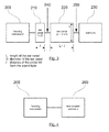
- Analogue models previously created and available in the literature, are obtained for the hearing instrument 40, the ear canal 10, and the eardrum 30, and are shown in the block schematic diagram of Fig. 3 (see for example LoPresti, "Electrical Analogs for Knowles Electronics, LLC. Transducers," Version 9.0, Aug. 14, 2007).
- the hearing instrument model 200 is followed by a model of the ear canal divided into two parts: (1) a first segment 210 having dimensions l x D, where l is the distance separating the probe microphone 50 from the end 44 of the hearing instrument sound tube 42 in Figs.
- D is the diameter of the ear canal model
- D is the diameter of the ear canal model
- a second segment 220 having a length of L- l and diameter D, where L represents the overall length of the ear canal 10.
- a typical ear canal has a length L of 13 mm and a diameter D of 7.5 mm.
- the ear canal segments 210 and 220 are followed by a model of the eardrum 230 having a predetermined value of acoustic impedance.
- the sound pressure level is simulated over the desired frequency range f 1 - f 2 , at pick off point 240, which represents the position of the probe microphone 50 employed to measure the sound pressure level in the person's ear canal 10 in Fig. 1 ( Fig. 6 , step 306).
- the difference between the results of the two simulations yields a simulated real-ear-to-coupler difference at the predetermined distance from the end 44 of the sound tube 42, defined as the simulated RECD_ l . ( Fig. 6 , step 310).
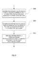
- any suitable optimization technique may be employed to minimize the differences between the measured and simulated real-ear-to-coupler difference at the predetermined distance from the end 44 of the sound tube 42 (simulated RECD_ l ) ( Fig. 7 , steps 312-316).
- Parameters L and D are varied and the simulations are repeated iteratively until a predetermined amount of acceptable error (or difference) has been reached ( Fig. 7 , steps 314-316).
- the optimized values of L and D represent a model (210-220-230) closest in simulated real-ear-to-coupler difference (simulated RECD_ l ) at the predetermined distance from the end 44 of the sound tube 42 over the desired frequency range to the measured RECD_ l for the ear canal 10.
- the sound pressure level over the frequency range is simulated using the model in Fig. 3 , but taking the simulated value at pick off point 250, which represents the location of the eardrum 230 ( Fig. 8 , step 318).
- the simulated real-ear-to-coupler difference at the eardrum 230 is obtained by subtracting the results of the simulation employing the model of the test coupler 260 ( Fig. 6 , 308; Fig. 8 , step 320).
- the simulated RECD_d may now be used to acoustically fit the hearing instrument to the user ( Fig. 8 , step 322).
- This parameter, RECD_d is added to the measurement made in step 302 in Fig. 5 , where the sound pressure level vs. frequency response was detected in the test coupler 100, yielding the sound pressure level at the eardrum 30 ( Fig. 9 , steps 324-326).
- the ear canal model may have a conical shape ( Fig. 10 , 400), tapering towards the eardrum 230, or may be stepped in a series of sections of decreasing or varying diameter ( Fig. 11 , 410; Fig. 12 , 420; respectively).
Abstract
Description
- A knowledge of the sound pressure level at the eardrum over the audible frequency range is desirable to acoustically fit a hearing instrument to a user's ear. The sound pressure level may be determined by using real ear-to-coupler difference (RECD) techniques to create an acoustic model of the user's ear canal.
- According to a first aspect of the invention, a method for acoustically fitting a hearing instrument positioned in an ear canal, the hearing instrument comprising a tip and a sound tube comprising an end at the tip of the hearing instrument, is proposed. The method comprises the steps of measuring the sound pressure level at a predetermined distance from the end of the sound tube of the hearing instrument positioned in the ear canal; measuring the sound pressure level at the predetermined distance from the end of the sound tube of the hearing instrument positioned in a test coupler; in response to measuring the sound pressure level in the ear canal and the test coupler, determining a measured real-ear-to-coupler difference at the predetermined distance from the end of the hearing instrument sound tube; simulating the sound pressure level at the predetermined distance from a model of a hearing instrument positioned in a model of the ear canal, where the ear canal model comprises a length and a diameter; simulating the sound pressure level at the predetermined distance from the model of a hearing instrument positioned in a model of the test coupler; in response to simulating the sound pressure level in the ear canal and the test coupler, determining a simulated real-ear-to-coupler difference at the predetermined distance from the model of a hearing instrument; optimizing the model of the ear canal, comprising (a) varying the length and/or diameter of the model of the ear canal; (b) simulating the sound pressure level at the predetermined distance from the model of the hearing instrument positioned in the model of the ear canal comprising a varied length and/or diameter; (c) determining the simulated real-ear-to-coupler difference at the predetermined distance from the model of the hearing instrument positioned in the model of the ear canal comprising a varied length and/or diameter; (d) determining the error between the measured real-ear-to-coupler difference at the predetermined distance from the hearing instrument and the simulated real-ear-to-coupler difference at the predetermined distance from the model of the hearing instrument; and iteratively repeating preceding steps (a) through (d) until the error is reduced to a predetermined amount, yielding optimized values of length and diameter for the ear canal model; simulating the sound pressure level at the eardrum generated by a model of the hearing instrument in the model of the ear canal comprising the optimized values of length and/or diameter; and determining the optimized simulated real-ear-to-coupler difference at the eardrum.
- According to a second aspect of the invention, a method for creating an optimized model of an ear canal for a hearing instrument positioned in the ear canal, the hearing instrument comprising a tip and a sound tube comprising an end at the tip of the hearing instrument, is proposed. The method comprises the steps of measuring the sound pressure level at a predetermined distance from the end of the sound tube of a hearing instrument positioned in the ear canal; measuring the sound pressure level at the predetermined distance from the end of the sound tube of the hearing instrument positioned in a test coupler; in response to measuring the sound pressure level in the ear canal and the test coupler, determining a measured real-ear-to-coupler difference at the predetermined distance from the end of the hearing instrument sound tube; simulating the sound pressure level at the predetermined distance from a model of a hearing instrument positioned in a model of the ear canal, where the ear canal model comprises a length and a diameter; simulating the sound pressure level at the predetermined distance from the model of a hearing instrument positioned in a model of the test coupler; in response to simulating the sound pressure level in the ear canal and the test coupler, determining a simulated real-ear-to-coupler difference at the predetermined distance from the model of a hearing instrument; and optimizing the model of the ear canal, comprising (a) varying the length and/or diameter of the model of the ear canal; (b) simulating the sound pressure level at the predetermined distance from the model of the hearing instrument positioned in the model of the ear canal comprising the varied length and/or diameter; (c) determining the simulated real-ear-to-coupler difference at the predetermined distance from the model of the hearing instrument positioned in the model of the ear canal comprising a varied length and/or diameter; (d) determining the error between the measured real-ear-to-coupler difference at the predetermined distance from the hearing instrument and the simulated real-ear-to-coupler difference at the predetermined distance from the model of the hearing instrument; and iteratively repeating preceding steps (a) through (d) until the error is reduced to a predetermined amount, yielding optimized values of length and diameter for the ear canal model.
- According to a third aspect of the invention, a method for acoustically fitting a hearing instrument positioned in an ear canal, the hearing instrument comprising a tip and a sound tube comprising an end at the tip of the hearing instrument. The method comprises the steps of calculating a measured real-ear-to-coupler difference at a predetermined distance from the end of the hearing instrument sound tube; calculating a simulated real-ear-to-coupler difference at the predetermined distance from the end of the hearing instrument sound tube; optimizing the model of the ear canal, comprising (a) determining the simulated real-ear-to-coupler difference at the predetermined distance from the model of the hearing instrument positioned in the model of the ear canal comprising a varied length and/or diameter; (b) determining the error between the measured real-ear-to-coupler difference at the predetermined distance from the hearing instrument and the simulated real-ear-to-coupler difference at the predetermined distance from the model of the hearing instrument; and iteratively repeating preceding steps (a) and (b) until the error is reduced to a predetermined value; and calculating an optimized simulated real-ear-to-coupler difference at the eardrum.
- According to a fourth aspect of the invention, a method for acoustically fitting a hearing instrument positioned in an ear canal, the hearing instrument comprising a tip and a sound tube comprising an end at the tip of the hearing instrument, is proposed. The method comprises the steps of measuring the real-ear-to-coupler difference in the ear canal at a predetermined distance from the end of the hearing instrument sound tube; simulating the real-ear-to-coupler difference at the predetermined distance from the end of a model of the hearing instrument in a model of the ear canal comprising a length and a diameter; and selecting values for the length and diameter of the model of the ear canal such that the differences between the measured and simulated real-ear-to-coupler differences at the predetermined distance are minimized to a predetermined level.
-
-
Fig. 1 is a schematic representation of a hearing instrument and probe microphone positioned in an ear canal; -
Fig. 2 is a schematic representation of a hearing instrument and probe microphone positioned in a test coupler; -
Fig. 3 is a schematic block diagram of a simulated hearing instrument, ear canal, and eardrum; -
Fig. 4 is a schematic block diagram of a simulated hearing instrument and test coupler; -
Figs. 5-9 are flow charts of procedures for acoustically fitting a hearing instrument; and -
Figs. 10, 11, and 12 illustrate alternative geometries for models of the ear canal. - To determine the sound pressure level at the eardrum of an occluded ear, the sound pressure level is measured in the user's ear canal at a predetermined distance from the end of the sound tube of a hearing instrument over the desired range of frequencies and then normalized using the frequency response detected in a test coupler to obtain the measured real-ear-to-coupler difference at the predetermined distance from the end of the sound tube. The sound pressure level is then simulated in a model of the user's ear canal, again over the desired range of frequencies, and once again normalized using a model of a test coupler, yielding a simulated real-ear-to-coupler difference at the predetermined distance from the end of the sound tube. Using an optimization procedure, the dimensions of the ear canal model are adjusted until the differences between the measured and the simulated values are minimized to a predetermined, acceptable amount. The optimized model of the ear canal is then used to obtain the real-ear-to-coupler difference at the eardrum or tympanic membrane. In turn, this parameter may be used to calculate the sound pressure level at the eardrum.
- As illustrated in
Fig. 1 , the sound pressure level in theear canal 10 is measured using ahearing instrument 40 to generate sound and aprobe microphone 50 to detect the generated sound. Thehearing instrument 40 resides in theear canal 10 between theear canal walls 20, facing the eardrum ortympanic membrane 30. InFigs. 1 and 2 , a connectingcable 52 for theprobe microphone 50 is shown in phantom, passing through the body of thehearing instrument 40, but it may be located in a channel on the exterior surface of thehearing instrument 40 or in a passage within the hearing instrument 40 (neither shown). - To minimize the near-field effects of the
hearing instrument 40 on the generated sound, theprobe microphone 50 is set apart and at a distance l from theend 44 of the hearinginstrument sound tube 42 at the tip of thehearing instrument 40. A suitable distance is 5 mm, as for example suggested inUS 2010/0202642, LoPresti et al. Sound is then generated over the desired range of frequencies f 1-f 2 and the sound pressure level versus frequency is measured using the probe microphone 50 (Fig. 5 , step 300). - Next, the
hearing instrument 40 and theprobe microphone 50 are inserted into thereceptacle 110 of thetest coupler 100 inFig. 2 . Where high frequencies (greater than 8 kHz) are of interest, thetest coupler 100 may for example have a volume of 0.4 cc. In a test coupler of this volume, the sound pressure level is assumed to be uniform throughout. Using the same offset of distance l for theprobe microphone 50, the sound pressure level is again measured (using the probe microphone 50) over the same range of frequencies f 1-f 2, yielding a frequency response for the instrument 40 (Fig. 5 , step 302). - The measurements in the
ear canal 10 and thetest coupler 100 are used to determine or calculate measured real-ear-to-coupler difference at the predetermined distance from theend 44 of thesound tube 42 at the tip of the hearing instrument, defined as the measured RECD_l. The real-ear-to-coupler difference, a parameter known to those in the hearing instrument art, is the difference between the results of the two measurements (Fig. 5 , step 304). - Analogue models, previously created and available in the literature, are obtained for the
hearing instrument 40, theear canal 10, and theeardrum 30, and are shown in the block schematic diagram ofFig. 3 (see for example LoPresti, "Electrical Analogs for Knowles Electronics, LLC. Transducers," Version 9.0, Aug. 14, 2007). Thehearing instrument model 200 is followed by a model of the ear canal divided into two parts: (1) afirst segment 210 having dimensions l x D, where l is the distance separating theprobe microphone 50 from theend 44 of the hearinginstrument sound tube 42 inFigs. 1 and 2, and D is the diameter of the ear canal model; and (2) asecond segment 220, having a length of L-l and diameter D, where L represents the overall length of theear canal 10. A typical ear canal has a length L of 13 mm and a diameter D of 7.5 mm. Theear canal segments eardrum 230 having a predetermined value of acoustic impedance. - Using the model in
Fig. 3 , the sound pressure level is simulated over the desired frequency range f 1-f 2, at pick offpoint 240, which represents the position of theprobe microphone 50 employed to measure the sound pressure level in the person'sear canal 10 inFig. 1 (Fig. 6 , step 306). A model of thetest coupler 260 having a volume v (for example 0.4 cc), shown inFig. 4 and now connected to thehearing instrument model 200, is used to simulate the sound pressure level in thetest coupler 100 ofFig. 2 , again over the frequency range f 1-f 2 (Fig. 6 , step 308). The difference between the results of the two simulations (the ear canal and test coupler models) yields a simulated real-ear-to-coupler difference at the predetermined distance from theend 44 of thesound tube 42, defined as the simulated RECD_l. (Fig. 6 , step 310). - To arrive at an optimized model of the ear canal, any suitable optimization technique may be employed to minimize the differences between the measured and simulated real-ear-to-coupler difference at the predetermined distance from the
end 44 of the sound tube 42 (simulated RECD_l) (Fig. 7 , steps 312-316). Parameters L and D are varied and the simulations are repeated iteratively until a predetermined amount of acceptable error (or difference) has been reached (Fig. 7 , steps 314-316). The optimized values of L and D represent a model (210-220-230) closest in simulated real-ear-to-coupler difference (simulated RECD_l) at the predetermined distance from theend 44 of thesound tube 42 over the desired frequency range to the measured RECD_l for theear canal 10. - Using the optimized model (by selecting the optimized values of L and D), the sound pressure level over the frequency range is simulated using the model in
Fig. 3 , but taking the simulated value at pick offpoint 250, which represents the location of the eardrum 230 (Fig. 8 , step 318). The simulated real-ear-to-coupler difference at theeardrum 230, defined as the simulated RECD_d, is obtained by subtracting the results of the simulation employing the model of the test coupler 260 (Fig. 6 , 308;Fig. 8 , step 320). - The simulated RECD_d may now be used to acoustically fit the hearing instrument to the user (
Fig. 8 , step 322). This parameter, RECD_d, is added to the measurement made instep 302 inFig. 5 , where the sound pressure level vs. frequency response was detected in thetest coupler 100, yielding the sound pressure level at the eardrum 30 (Fig. 9 , steps 324-326). - To more closely approximate the geometry of a human ear canal, the ear canal model (
segments 210, 220) may have a conical shape (Fig. 10 , 400), tapering towards theeardrum 230, or may be stepped in a series of sections of decreasing or varying diameter (Fig. 11 , 410;Fig. 12 , 420; respectively).
Claims (16)
- A method for acoustically fitting a hearing instrument positioned in an ear canal, the hearing instrument comprising a tip and a sound tube comprising an end at the tip of the hearing instrument, comprising:- measuring the sound pressure level at a predetermined distance from the end of the sound tube of the hearing instrument positioned in the ear canal;- measuring the sound pressure level at the predetermined distance from the end of the sound tube of the hearing instrument positioned in a test coupler;- in response to measuring the sound pressure level in the ear canal and the test coupler, determining a measured real-ear-to-coupler difference at the predetermined distance from the end of the hearing instrument sound tube;- simulating the sound pressure level at the predetermined distance from a model of a hearing instrument positioned in a model of the ear canal, where the ear canal model comprises a length and a diameter;- simulating the sound pressure level at the predetermined distance from the model of a hearing instrument positioned in a model of the test coupler;- in response to simulating the sound pressure level in the ear canal and the test coupler, determining a simulated real-ear-to-coupler difference at the predetermined distance from the model of a hearing instrument;- optimizing the model of the ear canal, comprising(a) varying the length and/or diameter of the model of the ear canal;(b) simulating the sound pressure level at the predetermined distance from the model of the hearing instrument positioned in the model of the ear canal comprising a varied length and/or diameter;(c) determining the simulated real-ear-to-coupler difference at the predetermined distance from the model of the hearing instrument positioned in the model of the ear canal comprising a varied length and/or diameter;(d) determining the error between the measured real-ear-to-coupler difference at the predetermined distance from the hearing instrument and the simulated real-ear-to-coupler difference at the predetermined distance from the model of the hearing instrument; anditeratively repeating preceding steps (a) through (d) until the error is reduced to a predetermined amount, yielding optimized values of length and diameter for the ear canal model;- simulating the sound pressure level at the eardrum generated by a model of the hearing instrument in the model of the ear canal comprising the optimized values of length and/or diameter; and- determining the optimized simulated real-ear-to-coupler difference at the eardrum.
- A method as set forth in claim 1, wherein- the determining of the measured real-ear-to-coupler difference at the predetermined distance from the end of the hearing instrument sound tube comprises calculating the difference between the measured sound pressure level in the ear canal and the measured sound pressure level in the test coupler;- determining the simulated real-ear-to-coupler difference at the predetermined distance from the model of a hearing instrument comprises calculating the difference between the simulated sound pressure level in the ear canal and the simulated sound pressure level in the test coupler;- determining the simulated real-ear-to-coupler difference in (c) comprises calculating the difference between the simulated sound pressure level in the ear canal and the simulated sound pressure level in the test coupler; and- determining the optimized simulated real-ear-to-coupler difference at the eardrum comprises calculating the difference between the optimized simulated sound pressure level and the simulated sound pressure level in the test coupler.
- A method as set forth in claim 1 or 2, further comprising adding the optimized simulated real-ear-to-coupler difference at the eardrum to the sound pressure level measured in the test coupler.
- A method as set forth in one of the preceding claims, where the sound pressure level is measured and simulated over a range of frequencies.
- A method as set forth in one of the preceding claims, where measuring the sound pressure level at a distance from a hearing instrument positioned in the ear canal comprises measuring the sound pressure level at a distance of 5 mm from the end of the hearing instrument sound tube.
- A method as set forth in one of the preceding claims, where measuring the sound pressure level at a predetermined distance from the hearing instrument positioned in a test coupler comprises measuring the sound pressure level in a test coupler comprising a volume of 0.4 cc.
- A method as set forth in one of the preceding claims, where the model of the ear canal comprises a taper from the hearing instrument towards the eardrum.
- A method as set forth in one of the preceding claims, where the model of the ear canal comprises a plurality of sections of decreasing or varying diameter.
- A method for creating an optimized model of an ear canal for a hearing instrument positioned in the ear canal, the hearing instrument comprising a tip and a sound tube comprising an end at the tip of the hearing instrument, comprising:- measuring the sound pressure level at a predetermined distance from the end of the sound tube of a hearing instrument positioned in the ear canal;- measuring the sound pressure level at the predetermined distance from the end of the sound tube of the hearing instrument positioned in a test coupler;- in response to measuring the sound pressure level in the ear canal and the test coupler, determining a measured real-ear-to-coupler difference at the predetermined distance from the end of the hearing instrument sound tube;- simulating the sound pressure level at the predetermined distance from a model of a hearing instrument positioned in a model of the ear canal, where the ear canal model comprises a length and a diameter;- simulating the sound pressure level at the predetermined distance from the model of a hearing instrument positioned in a model of the test coupler;- in response to simulating the sound pressure level in the ear canal and the test coupler, determining a simulated real-ear-to-coupler difference at the predetermined distance from the model of a hearing instrument; and- optimizing the model of the ear canal, comprisingiteratively repeating preceding steps (a) through (d) until the error is reduced to a predetermined amount, yielding optimized values of length and diameter for the ear canal model.(a) varying the length and/or diameter of the model of the ear canal;(b) simulating the sound pressure level at the predetermined distance from the model of the hearing instrument positioned in the model of the ear canal comprising the varied length and/or diameter;(c) determining the simulated real-ear-to-coupler difference at the predetermined distance from the model of the hearing instrument positioned in the model of the ear canal comprising a varied length and/or diameter;(d) determining the error between the measured real-ear-to-coupler difference at the predetermined distance from the hearing instrument and the simulated real-ear-to-coupler difference at the predetermined distance from the model of the hearing instrument; and
- A method as set forth in claim 9, wherein- the determining of the measured real-ear-to-coupler difference at the predetermined distance from the end of the hearing instrument sound tube comprises calculating the difference between the measured sound pressure level in the ear canal and the measured sound pressure level in the test coupler;- determining the simulated real-ear-to-coupler difference at the predetermined distance from the model of a hearing instrument comprises calculating the difference between the simulated sound pressure level in the ear canal and the simulated sound pressure level in the test coupler; and- determining the simulated real-ear-to-coupler difference in (c) comprises calculating the difference between the simulated sound pressure level in the ear canal and the simulated sound pressure level in the test coupler.
- A method for acoustically fitting a hearing instrument positioned in an ear canal, the hearing instrument comprising a tip and a sound tube comprising an end at the tip of the hearing instrument, comprising:- calculating a measured real-ear-to-coupler difference at a predetermined distance from the end of the hearing instrument sound tube;- calculating a simulated real-ear-to-coupler difference at the predetermined distance from the end of the hearing instrument sound tube;- optimizing the model of the ear canal, comprising(a) determining the simulated real-ear-to-coupler difference at the predetermined distance from the model of the hearing instrument positioned in the model of the ear canal comprising a varied length and/or diameter;(b) determining the error between the measured real-ear-to-coupler difference at the predetermined distance from the hearing instrument and the simulated real-ear-to-coupler difference at the predetermined distance from the model of the hearing instrument; anditeratively repeating preceding steps (a) and (b) until the error is reduced to a predetermined value; and- calculating an optimized simulated real-ear-to-coupler difference at the eardrum.
- A method as set forth in claim 11, wherein- the calculating of the measured real-ear-to-coupler difference at a predetermined distance from the end of the hearing instrument sound tube is based upon the difference between the sound pressure level measured in the ear canal at the predetermined distance and the sound pressure level measured in the test coupler;- the calculating of the simulated real-ear-to-coupler difference at the predetermined distance from the end of the hearing instrument sound tube is based upon the difference between the sound pressure level simulated in a model of the ear canal, comprising a length and a diameter, at the predetermined distance and the sound pressure level simulated in the test coupler;- the determining of the simulated real-ear-to-coupler difference in (a) is based upon the sound pressure level simulated at the predetermined distance from the model of the hearing instrument positioned in the model of the ear canal comprising a varied length and/or diameter; and- the calculating of an optimized simulated real-ear-to-coupler difference at the eardrum is based upon the difference between the sound pressure level simulated at the eardrum generated by a model of the hearing instrument in the model of the ear canal comprising the optimized values of length and/or diameter, and the sound pressure level simulated in the test coupler.
- A method as set forth in claims 11 or 12, further comprising adding the optimized simulated real-ear-to-coupler difference at the eardrum to the sound pressure level measured in the test coupler.
- A method for acoustically fitting a hearing instrument positioned in an ear canal, the hearing instrument comprising a tip and a sound tube comprising an end at the tip of the hearing instrument, comprising:- measuring the real-ear-to-coupler difference in the ear canal at a predetermined distance from the end of the hearing instrument sound tube;- simulating the real-ear-to-coupler difference at the predetermined distance from the end of a model of the hearing instrument in a model of the ear canal comprising a length and a diameter; and- selecting values for the length and diameter of the model of the ear canal such that the differences between the measured and simulated real-ear-to-coupler differences at the predetermined distance are minimized to a predetermined level.
- A method as set forth in claim 14, further comprising calculating the simulated real-ear-to-coupler difference at the eardrum.
- A method as set forth in claims 14 or 15, further comprising calculating the sound pressure frequency response at the eardrum.
Applications Claiming Priority (1)
| Application Number | Priority Date | Filing Date | Title |
|---|---|---|---|
| US13/710,961 US9008325B2 (en) | 2012-12-11 | 2012-12-11 | Method for determining the sound pressure level at the eardrum of an occluded ear |
Publications (2)
| Publication Number | Publication Date |
|---|---|
| EP2744227A1 true EP2744227A1 (en) | 2014-06-18 |
| EP2744227B1 EP2744227B1 (en) | 2015-10-14 |
Family
ID=49911139
Family Applications (1)
| Application Number | Title | Priority Date | Filing Date |
|---|---|---|---|
| EP13196500.6A Active EP2744227B1 (en) | 2012-12-11 | 2013-12-10 | Method for determining the sound pressure level at the eardrum of an occluded ear |
Country Status (3)
| Country | Link |
|---|---|
| US (1) | US9008325B2 (en) |
| EP (1) | EP2744227B1 (en) |
| DK (1) | DK2744227T3 (en) |
Cited By (2)
| Publication number | Priority date | Publication date | Assignee | Title |
|---|---|---|---|---|
| CN109495833A (en) * | 2017-09-13 | 2019-03-19 | 大北欧听力公司 | The method for self-calibrating of hearing device and related hearing device |
| US11558700B2 (en) | 2017-09-13 | 2023-01-17 | Gn Hearing A/S | Methods of estimating ear geometry and related hearing devices |
Families Citing this family (2)
| Publication number | Priority date | Publication date | Assignee | Title |
|---|---|---|---|---|
| US10567863B2 (en) | 2017-12-19 | 2020-02-18 | Revx Technologies, Inc. | System and method for configuring audio signals to compensate for acoustic changes of the ear |
| CN111629316A (en) * | 2020-05-15 | 2020-09-04 | 广东思派康电子科技有限公司 | Monitoring method and monitoring system for continuous playing test of sound box |
Citations (2)
| Publication number | Priority date | Publication date | Assignee | Title |
|---|---|---|---|---|
| WO2010016925A1 (en) * | 2008-08-08 | 2010-02-11 | Starkey Laboratories, Inc. | System for measuring sound pressure level |
| EP2207366A2 (en) * | 2009-01-12 | 2010-07-14 | Starkey Laboratories, Inc. | System to estimate the sound pressure level at eardrum using measurements away from the eardrum |
Family Cites Families (2)
| Publication number | Priority date | Publication date | Assignee | Title |
|---|---|---|---|---|
| ATE379949T1 (en) * | 2004-03-18 | 2007-12-15 | Widex As | METHOD AND EQUIPMENT FOR REAL EAR MEASUREMENTS |
| US8526651B2 (en) * | 2010-01-25 | 2013-09-03 | Sonion Nederland Bv | Receiver module for inflating a membrane in an ear device |
-
2012
- 2012-12-11 US US13/710,961 patent/US9008325B2/en active Active
-
2013
- 2013-12-10 EP EP13196500.6A patent/EP2744227B1/en active Active
- 2013-12-10 DK DK13196500.6T patent/DK2744227T3/en active
Patent Citations (2)
| Publication number | Priority date | Publication date | Assignee | Title |
|---|---|---|---|---|
| WO2010016925A1 (en) * | 2008-08-08 | 2010-02-11 | Starkey Laboratories, Inc. | System for measuring sound pressure level |
| EP2207366A2 (en) * | 2009-01-12 | 2010-07-14 | Starkey Laboratories, Inc. | System to estimate the sound pressure level at eardrum using measurements away from the eardrum |
Non-Patent Citations (3)
| Title |
|---|
| CHAN J C K ET AL: "ESTIMATION OF EARDRUM ACOUSTIC PRESSURE AND OF EAR CANAL LENGTH FROM REMOTE POINTS IN THE CANAL", THE JOURNAL OF THE ACOUSTICAL SOCIETY OF AMERICA, AMERICAN INSTITUTE OF PHYSICS FOR THE ACOUSTICAL SOCIETY OF AMERICA, NEW YORK, NY, US, vol. 87, no. 3, 1 March 1990 (1990-03-01), pages 1237 - 1247, XP009035813, ISSN: 0001-4966, DOI: 10.1121/1.398799 * |
| KEVIN J. MUNRO ET AL: "Measuring the Real-Ear to Coupler Difference Transfer Function With an Insert Earphone and a Hearing Instrument: Are They the Same?", EAR AND HEARING, vol. 26, no. 1, 1 February 2005 (2005-02-01), pages 27 - 34, XP055011871, DOI: 10.1097/00003446-200502000-00003 * |
| SALTYKOV OLEG ET AL: "Potential Errors of Real-Ear-to-Coupler-Difference Method Applied for a Prediction of Hearing Aid Performance in an Individual Ear", CONFERENCE: 47TH INTERNATIONAL CONFERENCE: MUSIC INDUCED HEARING DISORDERS; 20120601, AES, 60 EAST 42ND STREET, ROOM 2520 NEW YORK 10165-2520, USA, 20 June 2012 (2012-06-20), XP040574716 * |
Cited By (6)
| Publication number | Priority date | Publication date | Assignee | Title |
|---|---|---|---|---|
| CN109495833A (en) * | 2017-09-13 | 2019-03-19 | 大北欧听力公司 | The method for self-calibrating of hearing device and related hearing device |
| EP3457715A1 (en) * | 2017-09-13 | 2019-03-20 | GN Hearing A/S | Methods of self-calibrating of a hearing device and related hearing devices |
| EP3793219A1 (en) * | 2017-09-13 | 2021-03-17 | GN Hearing A/S | Methods of self-calibrating of a hearing device and related hearing devices |
| CN109495833B (en) * | 2017-09-13 | 2021-11-16 | 大北欧听力公司 | Self-calibration method for a hearing device and related hearing device |
| US11202159B2 (en) | 2017-09-13 | 2021-12-14 | Gn Hearing A/S | Methods of self-calibrating of a hearing device and related hearing devices |
| US11558700B2 (en) | 2017-09-13 | 2023-01-17 | Gn Hearing A/S | Methods of estimating ear geometry and related hearing devices |
Also Published As
| Publication number | Publication date |
|---|---|
| DK2744227T3 (en) | 2016-01-25 |
| US9008325B2 (en) | 2015-04-14 |
| US20140161267A1 (en) | 2014-06-12 |
| EP2744227B1 (en) | 2015-10-14 |
Similar Documents
| Publication | Publication Date | Title |
|---|---|---|
| US9872116B2 (en) | Apparatus and method for detecting earphone removal and insertion | |
| EP2207366B1 (en) | System to estimate the sound pressure level at eardrum using measurements away from the eardrum | |
| US6837857B2 (en) | Method for the recording of acoustic parameters for the customization of hearing aids | |
| AU2005203428B8 (en) | Method for obtaining real ear measurements using a hearing aid | |
| CN108702578B (en) | Method for performing real ear measurements and measurement system | |
| EP2744227A1 (en) | Method for determining the sound pressure level at the eardrum of an occluded ear | |
| US9414173B1 (en) | Fitting verification with in situ hearing test | |
| US9693159B2 (en) | Method of fitting a hearing aid and a hearing aid | |
| EP2842346B1 (en) | Human like ear simulator | |
| WO2018146609A1 (en) | Method and apparatus for measuring otoacoustic emissions | |
| US9654884B2 (en) | Method of fitting a hearing instrument, and impression tool | |
| Dragan et al. | Experimental study of displays in contralateral acoustic reflex auditory stimulation | |
| US9474473B2 (en) | Method to measure real-ear-to-coupler difference | |
| Mlynska et al. | Acoustic Parameters of IEC 60318–1 Ear Simulators: A Comparison of Measurement Methods | |
| CN117835110A (en) | Wearing tightness detection method and Bluetooth headset | |
| Schmidt et al. | Measurement of equal-loudness contours using eardrum pressure as reference signal | |
| Jarvis | Sound measurements | |
| CN116916231A (en) | Real ear analysis method and system and electronic equipment |
Legal Events
| Date | Code | Title | Description |
|---|---|---|---|
| PUAI | Public reference made under article 153(3) epc to a published international application that has entered the european phase |
Free format text: ORIGINAL CODE: 0009012 |
|
| 17P | Request for examination filed |
Effective date: 20131210 |
|
| AK | Designated contracting states |
Kind code of ref document: A1 Designated state(s): AL AT BE BG CH CY CZ DE DK EE ES FI FR GB GR HR HU IE IS IT LI LT LU LV MC MK MT NL NO PL PT RO RS SE SI SK SM TR |
|
| AX | Request for extension of the european patent |
Extension state: BA ME |
|
| R17P | Request for examination filed (corrected) |
Effective date: 20140606 |
|
| RBV | Designated contracting states (corrected) |
Designated state(s): AL AT BE BG CH CY CZ DE DK EE ES FI FR GB GR HR HU IE IS IT LI LT LU LV MC MK MT NL NO PL PT RO RS SE SI SK SM TR |
|
| GRAP | Despatch of communication of intention to grant a patent |
Free format text: ORIGINAL CODE: EPIDOSNIGR1 |
|
| INTG | Intention to grant announced |
Effective date: 20150527 |
|
| GRAS | Grant fee paid |
Free format text: ORIGINAL CODE: EPIDOSNIGR3 |
|
| GRAA | (expected) grant |
Free format text: ORIGINAL CODE: 0009210 |
|
| AK | Designated contracting states |
Kind code of ref document: B1 Designated state(s): AL AT BE BG CH CY CZ DE DK EE ES FI FR GB GR HR HU IE IS IT LI LT LU LV MC MK MT NL NO PL PT RO RS SE SI SK SM TR |
|
| REG | Reference to a national code |
Ref country code: GB Ref legal event code: FG4D |
|
| REG | Reference to a national code |
Ref country code: AT Ref legal event code: REF Ref document number: 755860 Country of ref document: AT Kind code of ref document: T Effective date: 20151015 Ref country code: CH Ref legal event code: EP |
|
| REG | Reference to a national code |
Ref country code: NL Ref legal event code: MP Effective date: 20151014 |
|
| REG | Reference to a national code |
Ref country code: IE Ref legal event code: FG4D |
|
| RAP2 | Party data changed (patent owner data changed or rights of a patent transferred) |
Owner name: SIVANTOS, INC. |
|
| REG | Reference to a national code |
Ref country code: DE Ref legal event code: R096 Ref document number: 602013003458 Country of ref document: DE |
|
| REG | Reference to a national code |
Ref country code: DE Ref legal event code: R082 Ref document number: 602013003458 Country of ref document: DE Representative=s name: FDST PATENTANWAELTE FREIER DOERR STAMMLER TSCH, DE |
|
| REG | Reference to a national code |
Ref country code: CH Ref legal event code: NV Representative=s name: E. BLUM AND CO. AG PATENT- UND MARKENANWAELTE , CH |
|
| REG | Reference to a national code |
Ref country code: FR Ref legal event code: PLFP Year of fee payment: 3 |
|
| REG | Reference to a national code |
Ref country code: DK Ref legal event code: T3 Effective date: 20160119 |
|
| REG | Reference to a national code |
Ref country code: LT Ref legal event code: MG4D |
|
| REG | Reference to a national code |
Ref country code: AT Ref legal event code: MK05 Ref document number: 755860 Country of ref document: AT Kind code of ref document: T Effective date: 20151014 |
|
| PG25 | Lapsed in a contracting state [announced via postgrant information from national office to epo] |
Ref country code: NL Free format text: LAPSE BECAUSE OF FAILURE TO SUBMIT A TRANSLATION OF THE DESCRIPTION OR TO PAY THE FEE WITHIN THE PRESCRIBED TIME-LIMIT Effective date: 20151014 Ref country code: LT Free format text: LAPSE BECAUSE OF FAILURE TO SUBMIT A TRANSLATION OF THE DESCRIPTION OR TO PAY THE FEE WITHIN THE PRESCRIBED TIME-LIMIT Effective date: 20151014 Ref country code: IS Free format text: LAPSE BECAUSE OF FAILURE TO SUBMIT A TRANSLATION OF THE DESCRIPTION OR TO PAY THE FEE WITHIN THE PRESCRIBED TIME-LIMIT Effective date: 20160214 Ref country code: NO Free format text: LAPSE BECAUSE OF FAILURE TO SUBMIT A TRANSLATION OF THE DESCRIPTION OR TO PAY THE FEE WITHIN THE PRESCRIBED TIME-LIMIT Effective date: 20160114 Ref country code: IT Free format text: LAPSE BECAUSE OF FAILURE TO SUBMIT A TRANSLATION OF THE DESCRIPTION OR TO PAY THE FEE WITHIN THE PRESCRIBED TIME-LIMIT Effective date: 20151014 Ref country code: HR Free format text: LAPSE BECAUSE OF FAILURE TO SUBMIT A TRANSLATION OF THE DESCRIPTION OR TO PAY THE FEE WITHIN THE PRESCRIBED TIME-LIMIT Effective date: 20151014 Ref country code: ES Free format text: LAPSE BECAUSE OF FAILURE TO SUBMIT A TRANSLATION OF THE DESCRIPTION OR TO PAY THE FEE WITHIN THE PRESCRIBED TIME-LIMIT Effective date: 20151014 |
|
| PG25 | Lapsed in a contracting state [announced via postgrant information from national office to epo] |
Ref country code: AT Free format text: LAPSE BECAUSE OF FAILURE TO SUBMIT A TRANSLATION OF THE DESCRIPTION OR TO PAY THE FEE WITHIN THE PRESCRIBED TIME-LIMIT Effective date: 20151014 Ref country code: BE Free format text: LAPSE BECAUSE OF NON-PAYMENT OF DUE FEES Effective date: 20151231 Ref country code: PL Free format text: LAPSE BECAUSE OF FAILURE TO SUBMIT A TRANSLATION OF THE DESCRIPTION OR TO PAY THE FEE WITHIN THE PRESCRIBED TIME-LIMIT Effective date: 20151014 Ref country code: SE Free format text: LAPSE BECAUSE OF FAILURE TO SUBMIT A TRANSLATION OF THE DESCRIPTION OR TO PAY THE FEE WITHIN THE PRESCRIBED TIME-LIMIT Effective date: 20151014 Ref country code: LV Free format text: LAPSE BECAUSE OF FAILURE TO SUBMIT A TRANSLATION OF THE DESCRIPTION OR TO PAY THE FEE WITHIN THE PRESCRIBED TIME-LIMIT Effective date: 20151014 Ref country code: FI Free format text: LAPSE BECAUSE OF FAILURE TO SUBMIT A TRANSLATION OF THE DESCRIPTION OR TO PAY THE FEE WITHIN THE PRESCRIBED TIME-LIMIT Effective date: 20151014 Ref country code: GR Free format text: LAPSE BECAUSE OF FAILURE TO SUBMIT A TRANSLATION OF THE DESCRIPTION OR TO PAY THE FEE WITHIN THE PRESCRIBED TIME-LIMIT Effective date: 20160115 Ref country code: RS Free format text: LAPSE BECAUSE OF FAILURE TO SUBMIT A TRANSLATION OF THE DESCRIPTION OR TO PAY THE FEE WITHIN THE PRESCRIBED TIME-LIMIT Effective date: 20151014 Ref country code: PT Free format text: LAPSE BECAUSE OF FAILURE TO SUBMIT A TRANSLATION OF THE DESCRIPTION OR TO PAY THE FEE WITHIN THE PRESCRIBED TIME-LIMIT Effective date: 20160215 |
|
| REG | Reference to a national code |
Ref country code: DE Ref legal event code: R097 Ref document number: 602013003458 Country of ref document: DE |
|
| PG25 | Lapsed in a contracting state [announced via postgrant information from national office to epo] |
Ref country code: CZ Free format text: LAPSE BECAUSE OF FAILURE TO SUBMIT A TRANSLATION OF THE DESCRIPTION OR TO PAY THE FEE WITHIN THE PRESCRIBED TIME-LIMIT Effective date: 20151014 Ref country code: LU Free format text: LAPSE BECAUSE OF FAILURE TO SUBMIT A TRANSLATION OF THE DESCRIPTION OR TO PAY THE FEE WITHIN THE PRESCRIBED TIME-LIMIT Effective date: 20151210 Ref country code: MC Free format text: LAPSE BECAUSE OF FAILURE TO SUBMIT A TRANSLATION OF THE DESCRIPTION OR TO PAY THE FEE WITHIN THE PRESCRIBED TIME-LIMIT Effective date: 20151014 |
|
| PLBE | No opposition filed within time limit |
Free format text: ORIGINAL CODE: 0009261 |
|
| STAA | Information on the status of an ep patent application or granted ep patent |
Free format text: STATUS: NO OPPOSITION FILED WITHIN TIME LIMIT |
|
| PG25 | Lapsed in a contracting state [announced via postgrant information from national office to epo] |
Ref country code: SK Free format text: LAPSE BECAUSE OF FAILURE TO SUBMIT A TRANSLATION OF THE DESCRIPTION OR TO PAY THE FEE WITHIN THE PRESCRIBED TIME-LIMIT Effective date: 20151014 Ref country code: SM Free format text: LAPSE BECAUSE OF FAILURE TO SUBMIT A TRANSLATION OF THE DESCRIPTION OR TO PAY THE FEE WITHIN THE PRESCRIBED TIME-LIMIT Effective date: 20151014 Ref country code: RO Free format text: LAPSE BECAUSE OF FAILURE TO SUBMIT A TRANSLATION OF THE DESCRIPTION OR TO PAY THE FEE WITHIN THE PRESCRIBED TIME-LIMIT Effective date: 20151014 Ref country code: EE Free format text: LAPSE BECAUSE OF FAILURE TO SUBMIT A TRANSLATION OF THE DESCRIPTION OR TO PAY THE FEE WITHIN THE PRESCRIBED TIME-LIMIT Effective date: 20151014 |
|
| 26N | No opposition filed |
Effective date: 20160715 |
|
| REG | Reference to a national code |
Ref country code: IE Ref legal event code: MM4A |
|
| PG25 | Lapsed in a contracting state [announced via postgrant information from national office to epo] |
Ref country code: IE Free format text: LAPSE BECAUSE OF NON-PAYMENT OF DUE FEES Effective date: 20151210 |
|
| PG25 | Lapsed in a contracting state [announced via postgrant information from national office to epo] |
Ref country code: SI Free format text: LAPSE BECAUSE OF FAILURE TO SUBMIT A TRANSLATION OF THE DESCRIPTION OR TO PAY THE FEE WITHIN THE PRESCRIBED TIME-LIMIT Effective date: 20151014 |
|
| REG | Reference to a national code |
Ref country code: FR Ref legal event code: PLFP Year of fee payment: 4 |
|
| PG25 | Lapsed in a contracting state [announced via postgrant information from national office to epo] |
Ref country code: BE Free format text: LAPSE BECAUSE OF FAILURE TO SUBMIT A TRANSLATION OF THE DESCRIPTION OR TO PAY THE FEE WITHIN THE PRESCRIBED TIME-LIMIT Effective date: 20151014 |
|
| PG25 | Lapsed in a contracting state [announced via postgrant information from national office to epo] |
Ref country code: BG Free format text: LAPSE BECAUSE OF FAILURE TO SUBMIT A TRANSLATION OF THE DESCRIPTION OR TO PAY THE FEE WITHIN THE PRESCRIBED TIME-LIMIT Effective date: 20151014 Ref country code: HU Free format text: LAPSE BECAUSE OF FAILURE TO SUBMIT A TRANSLATION OF THE DESCRIPTION OR TO PAY THE FEE WITHIN THE PRESCRIBED TIME-LIMIT; INVALID AB INITIO Effective date: 20131210 |
|
| PG25 | Lapsed in a contracting state [announced via postgrant information from national office to epo] |
Ref country code: CY Free format text: LAPSE BECAUSE OF FAILURE TO SUBMIT A TRANSLATION OF THE DESCRIPTION OR TO PAY THE FEE WITHIN THE PRESCRIBED TIME-LIMIT Effective date: 20151014 |
|
| PG25 | Lapsed in a contracting state [announced via postgrant information from national office to epo] |
Ref country code: MT Free format text: LAPSE BECAUSE OF FAILURE TO SUBMIT A TRANSLATION OF THE DESCRIPTION OR TO PAY THE FEE WITHIN THE PRESCRIBED TIME-LIMIT Effective date: 20151014 |
|
| REG | Reference to a national code |
Ref country code: FR Ref legal event code: PLFP Year of fee payment: 5 |
|
| PG25 | Lapsed in a contracting state [announced via postgrant information from national office to epo] |
Ref country code: MK Free format text: LAPSE BECAUSE OF FAILURE TO SUBMIT A TRANSLATION OF THE DESCRIPTION OR TO PAY THE FEE WITHIN THE PRESCRIBED TIME-LIMIT Effective date: 20151014 |
|
| PG25 | Lapsed in a contracting state [announced via postgrant information from national office to epo] |
Ref country code: AL Free format text: LAPSE BECAUSE OF FAILURE TO SUBMIT A TRANSLATION OF THE DESCRIPTION OR TO PAY THE FEE WITHIN THE PRESCRIBED TIME-LIMIT Effective date: 20151014 Ref country code: TR Free format text: LAPSE BECAUSE OF FAILURE TO SUBMIT A TRANSLATION OF THE DESCRIPTION OR TO PAY THE FEE WITHIN THE PRESCRIBED TIME-LIMIT Effective date: 20151014 |
|
| PGFP | Annual fee paid to national office [announced via postgrant information from national office to epo] |
Ref country code: CH Payment date: 20230103 Year of fee payment: 10 |
|
| PGFP | Annual fee paid to national office [announced via postgrant information from national office to epo] |
Ref country code: GB Payment date: 20231220 Year of fee payment: 11 |
|
| PGFP | Annual fee paid to national office [announced via postgrant information from national office to epo] |
Ref country code: FR Payment date: 20231219 Year of fee payment: 11 Ref country code: DK Payment date: 20231219 Year of fee payment: 11 Ref country code: DE Payment date: 20231214 Year of fee payment: 11 |