EP2744095B1 - Mechatronic system for an electrical device - Google Patents
Mechatronic system for an electrical device Download PDFInfo
- Publication number
- EP2744095B1 EP2744095B1 EP12401248.5A EP12401248A EP2744095B1 EP 2744095 B1 EP2744095 B1 EP 2744095B1 EP 12401248 A EP12401248 A EP 12401248A EP 2744095 B1 EP2744095 B1 EP 2744095B1
- Authority
- EP
- European Patent Office
- Prior art keywords
- motor
- udc
- phase
- inverter
- motors
- Prior art date
- Legal status (The legal status is an assumption and is not a legal conclusion. Google has not performed a legal analysis and makes no representation as to the accuracy of the status listed.)
- Active
Links
- 238000005406 washing Methods 0.000 claims description 12
- 230000001360 synchronised effect Effects 0.000 claims description 10
- 230000007935 neutral effect Effects 0.000 claims description 3
- 238000010411 cooking Methods 0.000 claims description 2
- 238000004804 winding Methods 0.000 description 21
- 239000007788 liquid Substances 0.000 description 4
- 230000006870 function Effects 0.000 description 3
- XLYOFNOQVPJJNP-UHFFFAOYSA-N water Substances O XLYOFNOQVPJJNP-UHFFFAOYSA-N 0.000 description 3
- 230000001276 controlling effect Effects 0.000 description 2
- 230000000694 effects Effects 0.000 description 2
- 238000009434 installation Methods 0.000 description 2
- 239000004065 semiconductor Substances 0.000 description 2
- UXUFTKZYJYGMGO-CMCWBKRRSA-N (2s,3s,4r,5r)-5-[6-amino-2-[2-[4-[3-(2-aminoethylamino)-3-oxopropyl]phenyl]ethylamino]purin-9-yl]-n-ethyl-3,4-dihydroxyoxolane-2-carboxamide Chemical compound O[C@@H]1[C@H](O)[C@@H](C(=O)NCC)O[C@H]1N1C2=NC(NCCC=3C=CC(CCC(=O)NCCN)=CC=3)=NC(N)=C2N=C1 UXUFTKZYJYGMGO-CMCWBKRRSA-N 0.000 description 1
- 206010041235 Snoring Diseases 0.000 description 1
- 230000004913 activation Effects 0.000 description 1
- 230000000903 blocking effect Effects 0.000 description 1
- 230000009849 deactivation Effects 0.000 description 1
- 230000007547 defect Effects 0.000 description 1
- 230000001419 dependent effect Effects 0.000 description 1
- 238000001514 detection method Methods 0.000 description 1
- 239000003599 detergent Substances 0.000 description 1
- 238000011156 evaluation Methods 0.000 description 1
- 230000005669 field effect Effects 0.000 description 1
- 238000000034 method Methods 0.000 description 1
- 238000012986 modification Methods 0.000 description 1
- 230000004048 modification Effects 0.000 description 1
- 230000008569 process Effects 0.000 description 1
- 230000001105 regulatory effect Effects 0.000 description 1
- 238000007789 sealing Methods 0.000 description 1
- 238000001228 spectrum Methods 0.000 description 1
- 229910001220 stainless steel Inorganic materials 0.000 description 1
- 239000010935 stainless steel Substances 0.000 description 1
Images

Classifications
-
- H—ELECTRICITY
- H02—GENERATION; CONVERSION OR DISTRIBUTION OF ELECTRIC POWER
- H02M—APPARATUS FOR CONVERSION BETWEEN AC AND AC, BETWEEN AC AND DC, OR BETWEEN DC AND DC, AND FOR USE WITH MAINS OR SIMILAR POWER SUPPLY SYSTEMS; CONVERSION OF DC OR AC INPUT POWER INTO SURGE OUTPUT POWER; CONTROL OR REGULATION THEREOF
- H02M5/00—Conversion of ac power input into ac power output, e.g. for change of voltage, for change of frequency, for change of number of phases
- H02M5/40—Conversion of ac power input into ac power output, e.g. for change of voltage, for change of frequency, for change of number of phases with intermediate conversion into dc
- H02M5/42—Conversion of ac power input into ac power output, e.g. for change of voltage, for change of frequency, for change of number of phases with intermediate conversion into dc by static converters
- H02M5/44—Conversion of ac power input into ac power output, e.g. for change of voltage, for change of frequency, for change of number of phases with intermediate conversion into dc by static converters using discharge tubes or semiconductor devices to convert the intermediate dc into ac
- H02M5/453—Conversion of ac power input into ac power output, e.g. for change of voltage, for change of frequency, for change of number of phases with intermediate conversion into dc by static converters using discharge tubes or semiconductor devices to convert the intermediate dc into ac using devices of a triode or transistor type requiring continuous application of a control signal
- H02M5/458—Conversion of ac power input into ac power output, e.g. for change of voltage, for change of frequency, for change of number of phases with intermediate conversion into dc by static converters using discharge tubes or semiconductor devices to convert the intermediate dc into ac using devices of a triode or transistor type requiring continuous application of a control signal using semiconductor devices only
-
- H—ELECTRICITY
- H02—GENERATION; CONVERSION OR DISTRIBUTION OF ELECTRIC POWER
- H02P—CONTROL OR REGULATION OF ELECTRIC MOTORS, ELECTRIC GENERATORS OR DYNAMO-ELECTRIC CONVERTERS; CONTROLLING TRANSFORMERS, REACTORS OR CHOKE COILS
- H02P5/00—Arrangements specially adapted for regulating or controlling the speed or torque of two or more electric motors
- H02P5/74—Arrangements specially adapted for regulating or controlling the speed or torque of two or more electric motors controlling two or more ac dynamo-electric motors
Definitions
- the invention relates to a mechatronic system with a frequency converter for operating an electric motor.
- the invention is therefore based on the object to provide a simple design and to be configured mechatronic system with a frequency converter and a plurality of motors to be controlled.
- the converter means of the converter is adapted to provide in addition to the first DC voltage in the DC link a further DC voltage for the DC link, which has a value in the range between the intermediate DC voltage and the reference potential, wherein at least one winding is connected at one end to the further DC voltage.
- the provision of the further, preferably constant DC voltage serves to connect the star point, which connects two ends of the motor winding.
- the inverter of the inverter comprises two half-bridges for driving a 2-phase motor, wherein the further DC voltage can be connected to a star point formed by two mutually connected ends of the motor windings.
- a two-phase motor for example, a synchronous motor with permanent magnet-equipped rotor, can be particularly simple and reliable powered by such a frequency converter, the individual phases must be designed for the partial voltages resulting from the difference from the first DC voltage minus the other DC voltage ,
- the frequency converter comprises at least one further inverter in the DC intermediate circuit for operating a further motor.
- the already mentioned converter device provides the DC voltage for several inverters for several motors, which leads to a saving of components compared to separate frequency converters.
- This also applies to the provision of further DC voltage for connecting respective winding ends of other motors.
- the provision of the first DC voltage, the further DC voltage and the reference potential can be referred to as a DC bus, since several inverters can be operated independently of one another on this bus.
- the converter device is set up to set or provide the further DC voltage at the value of approximately half the DC voltage.
- two-phase synchronous motors can be operated.
- the converter means comprises an electronic switch having a predefined continuous pulse width modulation duty cycle of at least about 0.5 to provide the further DC voltage.
- a rectifier such as diode bridge rectifier
- the frequency converter comprises a further, separate inverter with controlled half bridges for switching on and off the power supply for at least one winding of a further, three-phase synchronous motor or asynchronous motor. No connection to the additional DC voltage is provided for this motor, so that the maximum possible voltage from the first DC voltage compared to the reference potential is available for this motor for each phase.
- the energization is preferably provided for a drive motor of a drum in a washing machine or a dryer.
- the inverter is dimensioned such that at a rated line voltage of 230V AC voltage, a first DC voltage in the range of 230 V to 400 V and another DC voltage in the range 115 V to 200 V compared to the reference potential of 0V is provided.
- the invention relates to a mechatronic system, comprising an inverter in at least one of the embodiments described above, and at least two two-phase motors, which are connected to their operation on the inverter, wherein at least two windings, each connected to a winding end to a neutral point and connected to the further output voltage are connected.
- a mechatronic system comprising an inverter in at least one of the embodiments described above, and at least two two-phase motors, which are connected to their operation on the inverter, wherein at least two windings, each connected to a winding end to a neutral point and connected to the further output voltage are connected.
- the system comprises a further 3-phase or multi-phase motor, for example a synchronous motor or asynchronous motor, which is connected to the 3-phase inverter for control or operation.
- the three-phase motor is connected exclusively to the outputs of the inverter, with non-connected or not connected star point (s).
- the two-phase motors which are preferably designed for a smaller power or phase voltage, are connected with their star points to the center output for the further DC voltage.
- the invention further relates to an electrical device, such as a washing machine, dryer, dishwasher, refrigerator, extractor fan or cooking appliance, comprising a device control device and a mechatronic system of at least one embodiment as described above for driving a functional assembly for operating the electrical device, wherein the devices Control device is in operative connection with the control device of the frequency converter in order to appropriately parameterize or determine the sequences or the program-controlled device functions which relate to the drives.
- the controller of the frequency converter then controls the switches of the half-bridges based on these specifications, whereby a pulse width modulation is provided for generating the corresponding frequencies for the phase outputs.
- the 2-phase motors for pumps, drain pump or Umflutpumpe are provided, wherein the three-phase motor is provided for the rotary drive of the rotatably mounted drum.
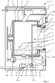
- Fig. 1 is shown in a purely schematic representation of a washing machine 1 with a trained as a tub 2 treatment tank.
- the position and direction information refer to the operational installation position of the washing machine 1.
- a rotatably mounted and driven by an electric motor 13 drum 3 is arranged, which moves the laundry items 8 located in the tub 2.
- the drum 3 is made in the present embodiment of stainless steel and provided with a plurality of openings for the flooding.
- the housing 4 has a loading opening 9, via which the interior of the drum 3 can be reached through the sealing sleeve 6.
- the loading opening 9 can be closed by means of a door 5.
- a radiator 7 is arranged, which can heat the washing liquid in the tub.
- an inlet valve 15 is sketched, which provides the running in of the water from the supply network.
- the water is passed through the connecting pipe 14 in the tub 2, wherein in the dispenser 11 entered detergent is flushed into the tub 2.
- a drain device 12 is arranged, which leads the spent washing liquid or the rinse water from the tub 2 to the drain line 12c, which usually opens into a sewer.
- the device control device 18 controls the inlet valve 15, the activity of the drain device 12, the drive motor 13, which is energized via the power unit or a frequency converter 16, and the radiator 7.
- the pump 17a is mounted in a flooding device.
- the pump 17a is connected to the drain pipe 12b on the inlet side and suction side, respectively, and can convey the washing liquid 19 therein through the pipe 17b into the upper portion of the tub 2 and the drum 3, respectively.
- the washing liquid 19 is injected or flows onto the laundry items 8 through the nozzle or the outlet 17c.
- Fig. 1 is also shown schematically that the pumps 12a and 17a each include an electric motor 12d, 17d, which serves to drive the pump 12a, 17a.
- both the motor 12d of the drain pump and the motor 17d of the bypass pump 17a are energized by the frequency converter 16.
- the frequency converter 16 is in operative connection with the device control device 18, so that the device controller 18 via a signal connection 18a the frequency converter 16 specifies the specifications when the respective pump motors 12d, 17d to be activated and when the operation should be done with the increased power supply ,
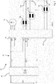
- Fig. 2 shows an embodiment of the inverter 16, which comprises a converter device 20, which provides from the AC input voltage, a first DC voltage UDC, another DC voltage UDC / 2 and a reference potential 0V.
- the inverter 24 includes 3 half-bridges, each comprising two electronic switches, such as bipolar transistors, combined field effect transistors or IGBTs, for energizing the 3-phase motor 13th is determined. The energization is carried out by means of three-phase alternating current, with which in the motor can produce the necessary for the rotation of the rotor rotating field. The half bridges are fed only from the first DC voltage UDC and the reference potential 0V of the intermediate circuit 22.
- 2-phase synchronous motors 12d, 17d, Xd each comprise an independently operated inverter 23.1, 23.2 ( Fig. 3 ).
- the windings 12u and 12v of the first motor 12d are each connected at their first end to a half-bridge of the first inverter 23.1.
- the respective second ends of the two windings 12u, 12v are connected together to form a star point 12k.
- the star point 12k is connected to the so-called middle or further DC voltage UDC / 2.
- the further motor 17d is connected with its windings 17u, 17v to the inverter 23.2 intended for it.
- the Fig. 3 shows the inverter 16 according to the invention with converter means 20 and the half-bridges S1A, S1B, S1C, S1D of the first inverter 23.1 connected in the intermediate circuit 22 for energizing the windings 12u, 12v of the first motor 12d.
- a further inverter S2A, S2B, S2C, S2D is connected in the same manner to the first DC voltage UDC and the reference potential 0V in order to provide the current supply for the further motor 17d.
- Other inverters for energizing further motors Xd can be added in the same way in the said intermediate circuit 22, depending on the requirements of the function.
- the control device 21 which comprises a microcontroller with memory, receives its commands and parameters by means of the data connection 18a from the device control device 18 (FIG. Fig. 1 ).
- the ports P1A to P1D for the first inverter 23.1 and the ports P2A to P2D are controlled for the further inverter 23.2 of the control device 21 or of the microcontroller uC, which in turn is connected to the electronic switches S1A, S1B, S1C, S1D their activation and deactivation are connected to effect current supply in the form of alternating currents with predetermined frequencies of the respective connected winding 12u, 12v by means of a pulse width modulation.
- s 4 ⁇ m2 of circuit breakers.
- 2-phase motors are only 4 circuit breakers.
- Two 2-phase motors result in 8 circuit breakers.
- two 2-phase motors can thus be a "commercial" microcontroller with e.g. use four independent PWM outputs (PWM pulse width modulation).
Description
Die Erfindung betrifft ein mechatronisches System mit einem Frequenzumrichter zum Betreiben eines elektrischen Motors.The invention relates to a mechatronic system with a frequency converter for operating an electric motor.
Bei motorischen Antrieben in Haushaltgeräten oder gewerblich eingesetzten Waschmaschinen, Trocknern oder Spülmaschinen werden zunehmend Frequenzumrichter verwendet, um die Leistung der Motoren optimal zu steuern. Ferner können die von den Geräten durchzuführenden Prozesse durch die Verwendung von Frequenzumrichtern zur Bestromung bzw. Steuerung der Motoren immer filigraner und optimaler gestaltet werden. Als Antriebe haben sich neben Asynchronmaschinen mit Kurzschlussläufer zunehmend Synchronmotoren mit Permanentmagnet-bestückten Rotoren verbreitet, die bei kompaktem und einfachem Aufbau eine hohe Leistung bereitstellen. Diese Motoren können als ein-, zwei-, oder dreiphasige Motoren konzipiert werden, je nach Anforderungen. Bei Pumpen haben sich ein-, oder zwei- oder dreiphasige Motoren als vorteilhaft erwiesen, da sie bei einfachem Aufbau ein hinreichendes Leistungsspektrum für den Verwendungszweck bieten. Für jede Phase eines dreiphasigen Motors ist dabei jeweils eine Halbbrücke mit jeweils zwei Leistungsschaltern notwendig; für jede Phase eines ein- oder zweiphasigen Motors ist für jede Phase eine sogenannte H-Brücke mit jeweils vier Leistungsschaltern vorgesehen.In motor drives in household appliances or commercially used washing machines, dryers or dishwashers increasingly frequency converters are used to optimally control the performance of the engines. Furthermore, the processes to be carried out by the devices by the use of frequency converters for energizing or controlling the motors can be made ever more filigree and optimal. As drives, in addition to asynchronous machines with squirrel-cage rotors, synchronous motors with permanent-magnet-equipped rotors have increasingly spread, providing high performance in a compact and simple design. These motors can be designed as single-, dual-, or three-phase motors, depending on requirements. In pumps, one-, two- or three-phase motors have proven to be advantageous because they offer a sufficient performance spectrum for the intended use with a simple structure. For each phase of a three-phase motor in each case a half-bridge with two circuit breakers is necessary; For each phase of a single- or two-phase motor, a so-called H-bridge with four circuit breakers is provided for each phase.
Für den Betrieb mehrerer 3-Phasen-Motoren sind üblicherweise sechs Leistungsschalter im Wechselrichter für jeweils einen Motor notwendig. Aus der
Aus der
Aus der
Aus der Veröffentlichung "
Der Erfindung liegt somit die Aufgabe zu Grunde, ein einfach aufgebautes und zu konfigurierendes mechatronisches System mit einem Frequenzumrichter und einer Mehrzahl von zu steuernden Motoren bereitzustellen.The invention is therefore based on the object to provide a simple design and to be configured mechatronic system with a frequency converter and a plurality of motors to be controlled.
Erfindungsgemäß wird die Aufgabe durch ein mechatronisches System gemäß Anspruch 1 und ein elektrisches Gerät gemäß Anspruch 6 gelöst. Vorteilhafte Ausgestaltungen und Weiterbildungen der Erfindung ergeben sich aus den jeweils nachfolgenden abhängigen Ansprüchen.According to the invention the object is achieved by a mechatronic system according to
Die mit der Erfindung erreichbaren Vorteile bestehen darin, dass im Vergleich zu herkömmlichen Wechselrichtern mit Modulation aller drei Halbbrücken für die Phasen des Motors nur zwei Halbbrücken gesteuert werden müssen, da der Sternpunktanschluss, den die miteinander verbundenen Wicklungsenden definieren, mit einem fest vordefinierten Potential versehen ist. Somit kann die maximal für einen Wicklungsstrang vorbestimmte Spannung an einem Wicklungsstrang des Motors angelegt werden, ohne dass zusätzliche und aufwändige Maßnahmen zur Spannungsbegrenzung oder Reduzierung nötig sind. Insbesondere ist diese Schaltungstopologie vorteilhaft anzuwenden bei Motoren mit sogenannter kleiner und mittlerer Leistung, beispielsweise für Gebläse oder Pumpen, bei denen die Ausnutzung der maximal möglichen Wechselrichter-Ausgangsspannung nicht erforderlich ist. Hierzu ist die Wandlereinrichtung des Umrichters dazu eingerichtet, zusätzlich zur ersten Gleichspannung im Zwischenkreis eine weitere Gleichspannung für den Zwischenkreis bereitzustellen, die einen Wert im Bereich zwischen der Zwischenkreisgleichspannung und dem Bezugspotential hat, wobei zumindest eine Wicklung mit einem Ende an der weiteren Gleichspannung angeschlossen ist. Die Bereitstellung der weiteren, vorzugsweise konstanten Gleichspannung dient zum Anschluss des Sternpunktes, der zwei Enden der Motorwicklung verbindet. Dadurch wird jede Motorwicklung jeweils nur mit einem Bruchteil der Spannung betrieben, die sich aus dem Potential der ersten Spannung gegenüber dem Bezugspotential ergibt.The achievable with the invention advantages are that compared to conventional inverters with modulation of all three half-bridges for the phases of the motor only two half-bridges must be controlled, since the neutral point terminal, which define the interconnected coil ends, is provided with a fixed predefined potential , Thus, the maximum voltage predetermined for one winding strand can be applied to one winding strand of the motor without the need for additional and expensive measures for limiting or reducing the voltage. In particular, this circuit topology is advantageous to apply to motors with so-called small and medium power, for example for blowers or pumps, where the utilization of the maximum possible inverter output voltage is not required. For this purpose, the converter means of the converter is adapted to provide in addition to the first DC voltage in the DC link a further DC voltage for the DC link, which has a value in the range between the intermediate DC voltage and the reference potential, wherein at least one winding is connected at one end to the further DC voltage. The provision of the further, preferably constant DC voltage serves to connect the star point, which connects two ends of the motor winding. As a result, each motor winding is operated in each case only with a fraction of the voltage resulting from the potential of the first voltage relative to the reference potential.
Der Wechselrichter des Umrichters umfasst zwei Halbbrücken zum Ansteuern eines 2-phasigen Motors, wobei die weitere Gleichspannung mit einem durch zwei miteinander verbundene Enden der Motorwicklungen gebildeten Sternpunkt verbunden werden kann. Ein zweiphasiger Motor, beispielsweise ein Synchronmotor mit Permanentmagnet-bestücktem Rotor, lässt sich besonders einfach und zuverlässig durch einen derartigen Frequenzumrichter bestromen, wobei die einzelnen Phasen auf die Teilspannungen ausgelegt sein müssen, die sich aus der Differenz von der ersten Gleichspannung abzüglich der weiteren Gleichspannung ergeben.The inverter of the inverter comprises two half-bridges for driving a 2-phase motor, wherein the further DC voltage can be connected to a star point formed by two mutually connected ends of the motor windings. A two-phase motor, for example, a synchronous motor with permanent magnet-equipped rotor, can be particularly simple and reliable powered by such a frequency converter, the individual phases must be designed for the partial voltages resulting from the difference from the first DC voltage minus the other DC voltage ,
Der Frequenzumrichter umfasst zumindest einen weiteren Wechselrichter im Gleichspannungszwischenkreis zum Betreiben eines weiteren Motors. Somit stellt die bereits besagte Wandlereinrichtung die Gleichspannung für mehrere Wechselrichter für mehrere Motoren bereit, was zu einer Einsparung von Bauteilen gegenüber separaten Frequenzumrichtern führt. Dies gilt ebenso für die Bereitstellung der weiteren Gleichspannung zum Anschluss jeweiliger Wicklungsenden weiterer Motoren. Zusammenfassend kann die Bereitstellung der ersten Gleichspannung, der weiteren Gleichspannung und des Bezugspotentials als DC-Bus bezeichnet werden, da an diesen Bus mehrere Wechselrichter unabhängig voneinander betrieben werden können.The frequency converter comprises at least one further inverter in the DC intermediate circuit for operating a further motor. Thus, the already mentioned converter device provides the DC voltage for several inverters for several motors, which leads to a saving of components compared to separate frequency converters. This also applies to the provision of further DC voltage for connecting respective winding ends of other motors. In summary, the provision of the first DC voltage, the further DC voltage and the reference potential can be referred to as a DC bus, since several inverters can be operated independently of one another on this bus.
In einer insgesamt zweckmäßigen Ausführung ist die Wandlereinrichtung dazu eingerichtet, die weitere Gleichspannung auf dem Wert etwa der halben Gleichspannung einzustellen bzw. bereitzustellen. Damit können symmetrisch aufgebaute, zweiphasige Synchronmotoren betrieben werden.In an overall expedient embodiment, the converter device is set up to set or provide the further DC voltage at the value of approximately half the DC voltage. Thus symmetrically constructed, two-phase synchronous motors can be operated.
Die Wandlereinrichtung umfasst einen elektronischen Schalter mit einem vordefinierten, kontinuierlichen, durch Pulsweitenmodulation bereitgestellten Tastgrad von zumindest etwa 0,5, zur Bereitstellung der weiteren Gleichspannung. In Kombination mit einem Gleichrichter, beispielsweise Dioden-Brückengleichrichter, kann auf einfache Weise eine zuverlässige Funktion bereitgestellt werden.The converter means comprises an electronic switch having a predefined continuous pulse width modulation duty cycle of at least about 0.5 to provide the further DC voltage. In combination with a rectifier, such as diode bridge rectifier, a reliable function can be provided in a simple manner.
Der Frequenzumrichter umfasst einen weiteren, separaten Wechselrichter mit gesteuerten Halbbrücken zum Ein- und Ausschalten der Stromzufuhr für zumindest eine Wicklung eines weiteren, dreiphasigen Synchronmotors oder Asynchronmotors. Für diesen Motor ist kein Anschluss an die weitere Gleichspannung vorgesehen, sodass für diesen Motor für jede Phase die maximal mögliche Spannung aus der ersten Gleichspannung gegenüber dem Bezugspotential zur Verfügung steht. Mit diesem Wechselrichter wird vorzugsweise die Bestromung für einen Antriebsmotor einer Trommel in einer Waschmaschine oder einem Trockner bereitgestellt.The frequency converter comprises a further, separate inverter with controlled half bridges for switching on and off the power supply for at least one winding of a further, three-phase synchronous motor or asynchronous motor. No connection to the additional DC voltage is provided for this motor, so that the maximum possible voltage from the first DC voltage compared to the reference potential is available for this motor for each phase. With this inverter, the energization is preferably provided for a drive motor of a drum in a washing machine or a dryer.
Insgesamt ist der Umrichter derart dimensioniert, dass bei einer Netznennspannung von 230V Wechselspannung eine erste Gleichspannung im Bereich von 230 V bis 400 V und eine weitere Gleichspannung im Bereich 115 V bis 200 V gegenüber dem Bezugspotential von 0V bereitgestellt wird.Overall, the inverter is dimensioned such that at a rated line voltage of 230V AC voltage, a first DC voltage in the range of 230 V to 400 V and another DC voltage in the range 115 V to 200 V compared to the reference potential of 0V is provided.
Die Erfindung betrifft ein mechatronisches System, umfassend einen Umrichter in wenigstens einer der vorstehend beschriebenen Ausführungen, und zumindest zwei zweiphasige Motoren, die zu ihrem Betrieb an dem Umrichter angeschlossen sind, wobei zumindest zwei Wicklungen mit jeweils einem Wicklungsende zu einem Sternpunkt zusammengeschaltet und an der weiteren Ausgangsspannung angeschlossen sind. Hierbei ist es möglich, die Bauteile des Frequenzumrichters sehr eng an die Eigenschaften des zu bestromenden Motors anzupassen bzw. entsprechend zu dimensionieren, sodass ein sehr effizientes und im Aufbau kostenoptimiertes System geschaffen wird.The invention relates to a mechatronic system, comprising an inverter in at least one of the embodiments described above, and at least two two-phase motors, which are connected to their operation on the inverter, wherein at least two windings, each connected to a winding end to a neutral point and connected to the further output voltage are connected. In this case, it is possible to adapt the components of the frequency converter very closely to the characteristics of the motor to be energized or to dimension them accordingly, so that a very efficient and cost-optimized system is created.
Das System umfasst einen weiteren 3- oder mehrphasigen Motor, beispielsweise einen Synchronmotor oder Asynchronmotor, der zur Ansteuerung bzw. zum Betrieb an den 3-phasigen Wechselrichter angeschlossen ist. Der dreiphasige Motor ist hierbei ausschließlich an die Ausgänge des Wechselrichters angeschlossen, mit nicht verbundenen bzw. nicht angeschlossenem/n Sternpunkt/en. Die zweiphasigen Motoren, die vorzugsweise für eine kleinere Leistung oder Phasenspannung ausgelegt sind, sind mit ihren Sternpunkten an den Mittelausgang für die weitere Gleichspannung angeschlossen. Somit wird mit einem einzigen, kompakten Frequenzumrichter eine Mehrzahl von unterschiedlichen Motoren, vorzugsweise Synchronmotoren mit Permanentmagnet bestückten Rotoren, für den Betrieb bestromt, sodass sich ein sehr übersichtlich gestaltetes System ergibt.The system comprises a further 3-phase or multi-phase motor, for example a synchronous motor or asynchronous motor, which is connected to the 3-phase inverter for control or operation. The three-phase motor is connected exclusively to the outputs of the inverter, with non-connected or not connected star point (s). The two-phase motors, which are preferably designed for a smaller power or phase voltage, are connected with their star points to the center output for the further DC voltage. Thus, with a single, compact frequency converter, a plurality of different motors, preferably synchronous motors equipped with permanent magnet rotors, energized for the operation, so that there is a very clearly designed system.
Die Erfindung betrifft ferner ein elektrisches Gerät, wie beispielsweise Waschmaschine, Trockner, Geschirrspüler, Kühlschrank, Dunstabzugshaube oder Gargerät, umfassend eine Geräte-Steuereinrichtung und ein mechatronisches System wenigstens einer Ausführung wie vorstehend beschrieben zum Antrieb einer Funktionsbaugruppe zum Betreiben des elektrischen Gerätes, wobei die Geräte-Steuereinrichtung mit der Steuereinrichtung des Frequenzumrichters in Wirkverbindung steht, um die Abläufe bzw. die programmgesteuerten Gerätefunktionen, die die Antriebe betreffen, einsprechend zu parametrieren oder zu bestimmen. Die Steuereinrichtung des Frequenzumrichters steuert dann anhand dieser Vorgaben die Schalter der Halbbrücken an, wodurch eine Pulsweitenmodulation zur Erzeugung der entsprechenden Frequenzen für die Phasenausgänge bereitgestellt wird. Bei einer Waschmaschine sind die 2-phasigen Motoren für Pumpen, Ablaufpumpe oder Umflutpumpe vorgesehen, wobei der dreiphasige Motor für den Drehantrieb der drehbar gelagerten Trommel vorgesehen ist.The invention further relates to an electrical device, such as a washing machine, dryer, dishwasher, refrigerator, extractor fan or cooking appliance, comprising a device control device and a mechatronic system of at least one embodiment as described above for driving a functional assembly for operating the electrical device, wherein the devices Control device is in operative connection with the control device of the frequency converter in order to appropriately parameterize or determine the sequences or the program-controlled device functions which relate to the drives. The controller of the frequency converter then controls the switches of the half-bridges based on these specifications, whereby a pulse width modulation is provided for generating the corresponding frequencies for the phase outputs. In a washing machine, the 2-phase motors for pumps, drain pump or Umflutpumpe are provided, wherein the three-phase motor is provided for the rotary drive of the rotatably mounted drum.
Ein Ausführungsbeispiel der Erfindung ist in den Zeichnungen rein schematisch dargestellt und wird nachfolgend näher beschrieben. Es zeigen
- Fig. 1
- ein elektrisches Gerät mit mehreren Motoren und einem Frequenzumrichter und
- Fig. 2, 3
- den Frequenzumrichter und ein mechatronisches System in einer schematischen Darstellung.
- Fig. 1
- an electrical device with multiple motors and a frequency converter and
- Fig. 2, 3rd
- the frequency converter and a mechatronic system in a schematic representation.
In
In
Die
Einige Vorteile der neuen Lösung lassen sich wie folgt zusammenfassen:
- Von jedem 2-Phasen-Motor ist jeweils ein Wicklungsende mit dem Potential UDC/2 vom DC-Bus (U DC, OV) des Spannungszwischenkreises verbunden. Die anderen beiden Wicklungsenden (Motorphasen) jedes 2-Phasen-Motors werden jeweils an eigene Halbbrücken, je bestehend aus zwei Leistungsschaltern S1A, S1B, S1C, S1D (Schalterpaar), angeschlossen. Das dem Frequenzumrichter zugeordnete Netzteil bzw. Wandlereinrichtung stellt an seinem Ausgang den DC-Bus zur Verfügung. Dieser umfasst zumindest die drei Potentiale UDC, UDC/2 und 0V. Die Bereitstellung von UDC/2 kann z.B. durch Modulation eines Schalterpaares (Halbbrücke) mit einem fixen Tastgrad in
etwa von
- Each of the two-phase motors has one winding end connected to the potential UDC / 2 from the DC bus (U DC, OV) of the voltage intermediate circuit. The other two Winding ends (motor phases) of each 2-phase motor are each connected to their own half-bridges, each consisting of two circuit breakers S1A, S1B, S1C, S1D (pair of switches). The power supply or converter device assigned to the frequency converter provides the DC bus at its output. This comprises at least the three potentials UDC, UDC / 2 and 0V. The provision of UDC / 2 can for example be done by modulating a pair of switches (half bridge) with a fixed duty cycle of about 0.5.
Der Wechselrichter 23 umfasst somit in der vorteilhaften Lösung für den Betrieb von (m2) 2-Phasen-Motoren nur eine Anzahl s = 4 · m2 Leistungsschaltern. Für den Betrieb von z.B. nur einem 2-Phasen-Motoren sind es also nur 4 Leistungsschalter. Für den Betrieb von z.B. zwei 2-Phasen-Motoren ergeben sich 8 Leistungsschalter.In the advantageous solution for the operation of (m2) 2-phase motors, the
Je mehr Motoren in einem Frequenzumrichter betrieben werden, desto größer ist das "Einsparpotential" an Leistungshalbleitern und Treibern bezogen auf die "klassischen" einzeln ausgebildeten Frequenzumrichter.The more motors are operated in a frequency converter, the greater the "savings potential" of power semiconductors and drivers relative to the "classic" individually designed frequency converter.
Ebenfalls reduziert sich damit die Peripherie zur Ansteuerung dieser Halbleiter.This also reduces the periphery for controlling these semiconductors.
Für den Betrieb von z.B. zwei 2-Phasen-Motoren lässt sich so ein "marktüblicher" Mikrocontroller mit z.B. vier unabhängigen PWM-Ausgängen (PWM-Puls-Weiten-Modulation) verwenden.For the operation of e.g. two 2-phase motors can thus be a "commercial" microcontroller with e.g. use four independent PWM outputs (PWM pulse width modulation).
Entsprechende Halbbrücken-Treiber können ebenfalls eingespart werden.Corresponding half-bridge drivers can also be saved.
Im Vergleich zu vorbekannten Wechselrichtern mit Modulation aller drei Ausgangsphasen, wie es in der
- Beliebiges Ein- und Ausschalten eines, mehrerer oder aller Motoren gleichzeitig und/oder sequentiell ist möglich.
- Geregelter Betrieb mit unterschiedlichen Drehzahlen (unterschiedlichen elektrischen Drehfrequenzen) der einzelnen Motoren möglich.
- Sensierung der Lastzustände jedes einzelnen Antriebs (zur weiteren Auswertung, z.B. "Schlürf-Erkennung" oder Blockierung oder Defekt, wie Unterbrechung oder Kurzschluss einer Wicklung eines Pumpenantriebs) ist möglich.
- Zusätzliche elektromechanische Bauteile, wie Relais, für eine Umschaltung der Phasenausgänge des Umrichters auf verschiedene Motoren kann entfallen.
- Any switching on and off of one, several or all motors simultaneously and / or sequentially is possible.
- Regulated operation with different speeds (different electrical rotation frequencies) of the individual motors possible.
- Sensing the load states of each individual drive (for further evaluation, eg "snore detection" or blocking or defect, such as interruption or short circuit of a winding of a pump drive) is possible.
- Additional electromechanical components, such as relays, for switching the phase outputs of the inverter to different motors can be omitted.
Claims (6)
- Mechatronic system, comprising:- a converter (16), comprising a converter device (20) that provides a direct voltage (UDC) and a reference potential (0V) from an AC input voltage (UN), the converter device (20) comprising an electronic switch having a predefined, continuous duty cycle, provided by pulse width modulation, of at least approximately 0.5, in order to provide, in a combination with a rectifier, an additional direct voltage (UDC/2) which is located in the range between the direct voltage (UDC) and the reference potential (0V);- a 3-phase motor (13) and an inverter (24) that comprises three half bridges for energising the 3-phase motor (13), the half bridges being fed only from the first direct voltage (UDC) and the reference potential (0V); and- at least two 2-phase synchronous motors (12d, 17d) and in each case an inverter (23.1, 23.2) having two half bridges, the first ends of the coils (12u, 12v, 17u, 17v) of each motor (12d, 17d) being connected to a corresponding half bridge of the associated inverter (23.1, 23.2) and the second ends of the coils (12u, 12v, 17u, 17v) being interconnected to form a neutral point (12k) that is connected to the additional direct voltage (UDC/2).
- Mechatronic system according to claim 1, wherein the additional direct voltage (UDC/2) is approximately the value of half the direct voltage (UDC).
- Mechatronic system according to either claim 1 or claim 2, wherein the rectifier is a full-wave diode bridge rectifier.
- Mechatronic system according to any of the preceding claims, the at least two 2-phase synchronous motors (12d, 17d) are motors having rotors that are equipped with permanent magnets.
- Mechatronic system according to any of the preceding claims, wherein the 3-phase motor (13) is formed as a synchronous motor or an asynchronous motor.
- Electric device (1), such as a washing machine, drier, dishwasher, refrigerator, extractor hood or cooking appliance, comprising an appliance control device (18) and a mechatronic system according to any of claims 1 to 5 for driving a functional unit (3, 12a, 17a) for operating the electric device (1), wherein the appliance control device (18) is operatively connected to the control device (21) of the convertor (16).
Priority Applications (1)
| Application Number | Priority Date | Filing Date | Title |
|---|---|---|---|
| EP12401248.5A EP2744095B1 (en) | 2012-12-12 | 2012-12-12 | Mechatronic system for an electrical device |
Applications Claiming Priority (1)
| Application Number | Priority Date | Filing Date | Title |
|---|---|---|---|
| EP12401248.5A EP2744095B1 (en) | 2012-12-12 | 2012-12-12 | Mechatronic system for an electrical device |
Publications (2)
| Publication Number | Publication Date |
|---|---|
| EP2744095A1 EP2744095A1 (en) | 2014-06-18 |
| EP2744095B1 true EP2744095B1 (en) | 2017-11-01 |
Family
ID=47681569
Family Applications (1)
| Application Number | Title | Priority Date | Filing Date |
|---|---|---|---|
| EP12401248.5A Active EP2744095B1 (en) | 2012-12-12 | 2012-12-12 | Mechatronic system for an electrical device |
Country Status (1)
| Country | Link |
|---|---|
| EP (1) | EP2744095B1 (en) |
Families Citing this family (5)
| Publication number | Priority date | Publication date | Assignee | Title |
|---|---|---|---|---|
| DE102015101043A1 (en) | 2015-01-26 | 2016-07-28 | Miele & Cie. Kg | Frequency converter for an electric motor, mechatronic system and washing machine |
| AT518721B1 (en) | 2016-05-25 | 2021-11-15 | B & R Ind Automation Gmbh | Control of long stator linear motor coils of a long stator linear motor stator |
| DE102016112636A1 (en) | 2016-07-11 | 2018-01-11 | Miele & Cie. Kg | Electrical supply circuit for supplying at least one inverter |
| DE102021132938A1 (en) | 2021-08-17 | 2023-02-23 | Miele & Cie. Kg | drive system |
| EP4199340A1 (en) | 2021-12-14 | 2023-06-21 | Miele & Cie. KG | Propulsion system |
Citations (1)
| Publication number | Priority date | Publication date | Assignee | Title |
|---|---|---|---|---|
| JP2008183087A (en) * | 2007-01-29 | 2008-08-14 | Matsushita Electric Ind Co Ltd | Motor driving device for washing and drying machine |
Family Cites Families (5)
| Publication number | Priority date | Publication date | Assignee | Title |
|---|---|---|---|---|
| JPS5771272A (en) * | 1980-10-17 | 1982-05-04 | Hitachi Ltd | Rectifying circuit |
| PL1691476T3 (en) | 2005-02-11 | 2009-10-30 | Grundfos Management As | Two phase permanent magnet motor |
| US7808201B2 (en) * | 2005-06-09 | 2010-10-05 | International Rectifier Corporation | Sensorless field oriented controller for two-phase motor |
| DE102007030072A1 (en) | 2007-06-29 | 2009-01-02 | BSH Bosch und Siemens Hausgeräte GmbH | Electric drive device for a water-conducting household appliance |
| JP4744505B2 (en) * | 2007-12-19 | 2011-08-10 | 三菱電機株式会社 | Motor drive control device, motor drive control method and coordinate conversion method, ventilation fan, liquid pump, blower, refrigerant compressor, air conditioner, and refrigerator |
-
2012
- 2012-12-12 EP EP12401248.5A patent/EP2744095B1/en active Active
Patent Citations (1)
| Publication number | Priority date | Publication date | Assignee | Title |
|---|---|---|---|---|
| JP2008183087A (en) * | 2007-01-29 | 2008-08-14 | Matsushita Electric Ind Co Ltd | Motor driving device for washing and drying machine |
Non-Patent Citations (2)
| Title |
|---|
| GUI-JIA SU ET AL: "An integrated traction and compressor drive system for EV/HEV applications", APPLIED POWER ELECTRONICS CONFERENCE AND EXPOSITION, 2005. APEC 2005. TWENTIETH ANNUAL IEEE AUSTIN, TX, USA 6-10 MARCH 2005, PISCATAWAY, NJ, USA,IEEE, US, vol. 2, 6 March 2005 (2005-03-06), pages 719 - 725Vol.2, XP010809315, ISBN: 978-0-7803-8975-5, DOI: 10.1109/APEC.2005.1453049 * |
| HOLMES D G ET AL: "VARIABLE SPEED CONTROL OF SINGLE AND TWO PHASE INDUCTION MOTORS USING A THREE PHASE VOLTAGE SOURCE INVERTER", CONFERENCE RECORD OF THE INDUSTRY APPLICATIONS CONFERENCE IAS ANNUAL MEETING. TORONTO, OCT. 3 - 6, 1993; [CONFERENCE RECORD OF THE INDUSTRY APPLICATIONS CONFERENCE IAS ANNUAL MEETING], NEW YORK, IEEE, US, vol. PART 01, 3 October 1993 (1993-10-03), pages 613 - 620, XP000427482 * |
Also Published As
| Publication number | Publication date |
|---|---|
| EP2744095A1 (en) | 2014-06-18 |
Similar Documents
| Publication | Publication Date | Title |
|---|---|---|
| EP2744095B1 (en) | Mechatronic system for an electrical device | |
| EP2162046B1 (en) | Electric drive unit for a water-bearing domestic appliance | |
| EP2217754B1 (en) | Circuit arrangements for operating a household appliance | |
| EP1284540A2 (en) | Dishwasher-pumpdrive | |
| DE102011108686A1 (en) | Electric engine system | |
| WO2016045920A1 (en) | Method for operating a circuit assembly | |
| EP1532306B1 (en) | Household machine | |
| DE102010042491A1 (en) | Pump device for a domestic appliance, domestic appliance and method for operating a drive motor | |
| EP3905512A1 (en) | Household appliance with a motor which can be switched on to an alternating voltage network | |
| EP1698032A1 (en) | Method for the operation of a converter circuit of a washing machine or a tumble dryer | |
| DE102011078917A1 (en) | Household appliance e.g. condensation dryer has separate electrical stators that are associated with rotors mounted in motor housing, so that rotors are driven independently | |
| DE102016001474A1 (en) | Drive comprising an electric motor, in particular a three-phase motor, which can be fed by a converter, and a method for operating a drive | |
| EP3301807B1 (en) | Two strand synchronous drive | |
| DE10127670A1 (en) | Controlling brushless 3-phase electric motor, involves using block commutation and operating motor with commutation angle less than 180 degrees and greater than 120 degrees | |
| EP1633039A1 (en) | Control method for an electrical motor and drive to carry out the method | |
| EP3061182B1 (en) | Method for controlling a brushless motor | |
| EP2086094A2 (en) | Permanently excited electric machine for a household appliance | |
| EP4199340A1 (en) | Propulsion system | |
| EP4358391A1 (en) | Propulsion system | |
| DE102007009604A1 (en) | Household device i.e. dishwasher, has inverter attached to electronically commutated motor or arranged in motor proximity, and supply unit spatially disconnected from motor and from inverter | |
| DE102015101043A1 (en) | Frequency converter for an electric motor, mechatronic system and washing machine | |
| DE102021132938A1 (en) | drive system | |
| EP4142146A1 (en) | Drive system | |
| EP3301808A1 (en) | Two-strand single-phase synchronous drive | |
| DE4215551A1 (en) | Drive unit for automatic washing machines - with asynchronous motor with two stator phases, one with AC coil for low speed range |
Legal Events
| Date | Code | Title | Description |
|---|---|---|---|
| PUAI | Public reference made under article 153(3) epc to a published international application that has entered the european phase |
Free format text: ORIGINAL CODE: 0009012 |
|
| 17P | Request for examination filed |
Effective date: 20121212 |
|
| AK | Designated contracting states |
Kind code of ref document: A1 Designated state(s): AL AT BE BG CH CY CZ DE DK EE ES FI FR GB GR HR HU IE IS IT LI LT LU LV MC MK MT NL NO PL PT RO RS SE SI SK SM TR |
|
| AX | Request for extension of the european patent |
Extension state: BA ME |
|
| R17P | Request for examination filed (corrected) |
Effective date: 20141218 |
|
| RBV | Designated contracting states (corrected) |
Designated state(s): AL AT BE BG CH CY CZ DE DK EE ES FI FR GB GR HR HU IE IS IT LI LT LU LV MC MK MT NL NO PL PT RO RS SE SI SK SM TR |
|
| 17Q | First examination report despatched |
Effective date: 20160127 |
|
| REG | Reference to a national code |
Ref country code: DE Ref legal event code: R079 Ref document number: 502012011567 Country of ref document: DE Free format text: PREVIOUS MAIN CLASS: H02M0007060000 Ipc: H02P0005740000 |
|
| GRAP | Despatch of communication of intention to grant a patent |
Free format text: ORIGINAL CODE: EPIDOSNIGR1 |
|
| RIC1 | Information provided on ipc code assigned before grant |
Ipc: H02P 6/04 20160101ALI20170530BHEP Ipc: H02P 5/74 20060101AFI20170530BHEP Ipc: H02M 7/06 20060101ALI20170530BHEP |
|
| INTG | Intention to grant announced |
Effective date: 20170619 |
|
| GRAS | Grant fee paid |
Free format text: ORIGINAL CODE: EPIDOSNIGR3 |
|
| GRAA | (expected) grant |
Free format text: ORIGINAL CODE: 0009210 |
|
| AK | Designated contracting states |
Kind code of ref document: B1 Designated state(s): AL AT BE BG CH CY CZ DE DK EE ES FI FR GB GR HR HU IE IS IT LI LT LU LV MC MK MT NL NO PL PT RO RS SE SI SK SM TR |
|
| REG | Reference to a national code |
Ref country code: GB Ref legal event code: FG4D Free format text: NOT ENGLISH |
|
| REG | Reference to a national code |
Ref country code: CH Ref legal event code: EP Ref country code: AT Ref legal event code: REF Ref document number: 942979 Country of ref document: AT Kind code of ref document: T Effective date: 20171115 Ref country code: DE Ref legal event code: R084 Ref document number: 502012011567 Country of ref document: DE |
|
| REG | Reference to a national code |
Ref country code: IE Ref legal event code: FG4D Free format text: LANGUAGE OF EP DOCUMENT: GERMAN |
|
| REG | Reference to a national code |
Ref country code: GB Ref legal event code: 746 Effective date: 20171115 |
|
| REG | Reference to a national code |
Ref country code: DE Ref legal event code: R096 Ref document number: 502012011567 Country of ref document: DE |
|
| REG | Reference to a national code |
Ref country code: FR Ref legal event code: PLFP Year of fee payment: 6 |
|
| REG | Reference to a national code |
Ref country code: NL Ref legal event code: MP Effective date: 20171101 |
|
| REG | Reference to a national code |
Ref country code: LT Ref legal event code: MG4D |
|
| PG25 | Lapsed in a contracting state [announced via postgrant information from national office to epo] |
Ref country code: SE Free format text: LAPSE BECAUSE OF FAILURE TO SUBMIT A TRANSLATION OF THE DESCRIPTION OR TO PAY THE FEE WITHIN THE PRESCRIBED TIME-LIMIT Effective date: 20171101 Ref country code: FI Free format text: LAPSE BECAUSE OF FAILURE TO SUBMIT A TRANSLATION OF THE DESCRIPTION OR TO PAY THE FEE WITHIN THE PRESCRIBED TIME-LIMIT Effective date: 20171101 Ref country code: NL Free format text: LAPSE BECAUSE OF FAILURE TO SUBMIT A TRANSLATION OF THE DESCRIPTION OR TO PAY THE FEE WITHIN THE PRESCRIBED TIME-LIMIT Effective date: 20171101 Ref country code: ES Free format text: LAPSE BECAUSE OF FAILURE TO SUBMIT A TRANSLATION OF THE DESCRIPTION OR TO PAY THE FEE WITHIN THE PRESCRIBED TIME-LIMIT Effective date: 20171101 Ref country code: LT Free format text: LAPSE BECAUSE OF FAILURE TO SUBMIT A TRANSLATION OF THE DESCRIPTION OR TO PAY THE FEE WITHIN THE PRESCRIBED TIME-LIMIT Effective date: 20171101 Ref country code: NO Free format text: LAPSE BECAUSE OF FAILURE TO SUBMIT A TRANSLATION OF THE DESCRIPTION OR TO PAY THE FEE WITHIN THE PRESCRIBED TIME-LIMIT Effective date: 20180201 |
|
| PG25 | Lapsed in a contracting state [announced via postgrant information from national office to epo] |
Ref country code: LV Free format text: LAPSE BECAUSE OF FAILURE TO SUBMIT A TRANSLATION OF THE DESCRIPTION OR TO PAY THE FEE WITHIN THE PRESCRIBED TIME-LIMIT Effective date: 20171101 Ref country code: RS Free format text: LAPSE BECAUSE OF FAILURE TO SUBMIT A TRANSLATION OF THE DESCRIPTION OR TO PAY THE FEE WITHIN THE PRESCRIBED TIME-LIMIT Effective date: 20171101 Ref country code: HR Free format text: LAPSE BECAUSE OF FAILURE TO SUBMIT A TRANSLATION OF THE DESCRIPTION OR TO PAY THE FEE WITHIN THE PRESCRIBED TIME-LIMIT Effective date: 20171101 Ref country code: BG Free format text: LAPSE BECAUSE OF FAILURE TO SUBMIT A TRANSLATION OF THE DESCRIPTION OR TO PAY THE FEE WITHIN THE PRESCRIBED TIME-LIMIT Effective date: 20180201 Ref country code: GR Free format text: LAPSE BECAUSE OF FAILURE TO SUBMIT A TRANSLATION OF THE DESCRIPTION OR TO PAY THE FEE WITHIN THE PRESCRIBED TIME-LIMIT Effective date: 20180202 Ref country code: IS Free format text: LAPSE BECAUSE OF FAILURE TO SUBMIT A TRANSLATION OF THE DESCRIPTION OR TO PAY THE FEE WITHIN THE PRESCRIBED TIME-LIMIT Effective date: 20180301 |
|
| PG25 | Lapsed in a contracting state [announced via postgrant information from national office to epo] |
Ref country code: EE Free format text: LAPSE BECAUSE OF FAILURE TO SUBMIT A TRANSLATION OF THE DESCRIPTION OR TO PAY THE FEE WITHIN THE PRESCRIBED TIME-LIMIT Effective date: 20171101 Ref country code: CY Free format text: LAPSE BECAUSE OF FAILURE TO SUBMIT A TRANSLATION OF THE DESCRIPTION OR TO PAY THE FEE WITHIN THE PRESCRIBED TIME-LIMIT Effective date: 20171101 Ref country code: CZ Free format text: LAPSE BECAUSE OF FAILURE TO SUBMIT A TRANSLATION OF THE DESCRIPTION OR TO PAY THE FEE WITHIN THE PRESCRIBED TIME-LIMIT Effective date: 20171101 Ref country code: SK Free format text: LAPSE BECAUSE OF FAILURE TO SUBMIT A TRANSLATION OF THE DESCRIPTION OR TO PAY THE FEE WITHIN THE PRESCRIBED TIME-LIMIT Effective date: 20171101 Ref country code: DK Free format text: LAPSE BECAUSE OF FAILURE TO SUBMIT A TRANSLATION OF THE DESCRIPTION OR TO PAY THE FEE WITHIN THE PRESCRIBED TIME-LIMIT Effective date: 20171101 |
|
| REG | Reference to a national code |
Ref country code: CH Ref legal event code: PL |
|
| REG | Reference to a national code |
Ref country code: DE Ref legal event code: R097 Ref document number: 502012011567 Country of ref document: DE |
|
| PG25 | Lapsed in a contracting state [announced via postgrant information from national office to epo] |
Ref country code: PL Free format text: LAPSE BECAUSE OF FAILURE TO SUBMIT A TRANSLATION OF THE DESCRIPTION OR TO PAY THE FEE WITHIN THE PRESCRIBED TIME-LIMIT Effective date: 20171101 Ref country code: RO Free format text: LAPSE BECAUSE OF FAILURE TO SUBMIT A TRANSLATION OF THE DESCRIPTION OR TO PAY THE FEE WITHIN THE PRESCRIBED TIME-LIMIT Effective date: 20171101 Ref country code: SM Free format text: LAPSE BECAUSE OF FAILURE TO SUBMIT A TRANSLATION OF THE DESCRIPTION OR TO PAY THE FEE WITHIN THE PRESCRIBED TIME-LIMIT Effective date: 20171101 |
|
| PLBE | No opposition filed within time limit |
Free format text: ORIGINAL CODE: 0009261 |
|
| STAA | Information on the status of an ep patent application or granted ep patent |
Free format text: STATUS: NO OPPOSITION FILED WITHIN TIME LIMIT |
|
| REG | Reference to a national code |
Ref country code: IE Ref legal event code: MM4A |
|
| PG25 | Lapsed in a contracting state [announced via postgrant information from national office to epo] |
Ref country code: LU Free format text: LAPSE BECAUSE OF NON-PAYMENT OF DUE FEES Effective date: 20171212 Ref country code: MT Free format text: LAPSE BECAUSE OF FAILURE TO SUBMIT A TRANSLATION OF THE DESCRIPTION OR TO PAY THE FEE WITHIN THE PRESCRIBED TIME-LIMIT Effective date: 20171101 |
|
| 26N | No opposition filed |
Effective date: 20180802 |
|
| REG | Reference to a national code |
Ref country code: BE Ref legal event code: MM Effective date: 20171231 |
|
| PG25 | Lapsed in a contracting state [announced via postgrant information from national office to epo] |
Ref country code: IE Free format text: LAPSE BECAUSE OF NON-PAYMENT OF DUE FEES Effective date: 20171212 |
|
| PG25 | Lapsed in a contracting state [announced via postgrant information from national office to epo] |
Ref country code: SI Free format text: LAPSE BECAUSE OF FAILURE TO SUBMIT A TRANSLATION OF THE DESCRIPTION OR TO PAY THE FEE WITHIN THE PRESCRIBED TIME-LIMIT Effective date: 20171101 Ref country code: CH Free format text: LAPSE BECAUSE OF NON-PAYMENT OF DUE FEES Effective date: 20171231 Ref country code: LI Free format text: LAPSE BECAUSE OF NON-PAYMENT OF DUE FEES Effective date: 20171231 Ref country code: BE Free format text: LAPSE BECAUSE OF NON-PAYMENT OF DUE FEES Effective date: 20171231 |
|
| REG | Reference to a national code |
Ref country code: AT Ref legal event code: MM01 Ref document number: 942979 Country of ref document: AT Kind code of ref document: T Effective date: 20171212 |
|
| PG25 | Lapsed in a contracting state [announced via postgrant information from national office to epo] |
Ref country code: AT Free format text: LAPSE BECAUSE OF NON-PAYMENT OF DUE FEES Effective date: 20171212 |
|
| PG25 | Lapsed in a contracting state [announced via postgrant information from national office to epo] |
Ref country code: HU Free format text: LAPSE BECAUSE OF FAILURE TO SUBMIT A TRANSLATION OF THE DESCRIPTION OR TO PAY THE FEE WITHIN THE PRESCRIBED TIME-LIMIT; INVALID AB INITIO Effective date: 20121212 Ref country code: MC Free format text: LAPSE BECAUSE OF FAILURE TO SUBMIT A TRANSLATION OF THE DESCRIPTION OR TO PAY THE FEE WITHIN THE PRESCRIBED TIME-LIMIT Effective date: 20171101 |
|
| PG25 | Lapsed in a contracting state [announced via postgrant information from national office to epo] |
Ref country code: MK Free format text: LAPSE BECAUSE OF FAILURE TO SUBMIT A TRANSLATION OF THE DESCRIPTION OR TO PAY THE FEE WITHIN THE PRESCRIBED TIME-LIMIT Effective date: 20171101 |
|
| PG25 | Lapsed in a contracting state [announced via postgrant information from national office to epo] |
Ref country code: PT Free format text: LAPSE BECAUSE OF FAILURE TO SUBMIT A TRANSLATION OF THE DESCRIPTION OR TO PAY THE FEE WITHIN THE PRESCRIBED TIME-LIMIT Effective date: 20171101 |
|
| PG25 | Lapsed in a contracting state [announced via postgrant information from national office to epo] |
Ref country code: AL Free format text: LAPSE BECAUSE OF FAILURE TO SUBMIT A TRANSLATION OF THE DESCRIPTION OR TO PAY THE FEE WITHIN THE PRESCRIBED TIME-LIMIT Effective date: 20171101 |
|
| P01 | Opt-out of the competence of the unified patent court (upc) registered |
Effective date: 20230529 |
|
| PGFP | Annual fee paid to national office [announced via postgrant information from national office to epo] |
Ref country code: GB Payment date: 20231219 Year of fee payment: 12 |
|
| PGFP | Annual fee paid to national office [announced via postgrant information from national office to epo] |
Ref country code: TR Payment date: 20231129 Year of fee payment: 12 Ref country code: IT Payment date: 20231221 Year of fee payment: 12 Ref country code: FR Payment date: 20231226 Year of fee payment: 12 Ref country code: DE Payment date: 20231231 Year of fee payment: 12 |