EP2744088A2 - Motor - Google Patents
Motor Download PDFInfo
- Publication number
- EP2744088A2 EP2744088A2 EP13197223.4A EP13197223A EP2744088A2 EP 2744088 A2 EP2744088 A2 EP 2744088A2 EP 13197223 A EP13197223 A EP 13197223A EP 2744088 A2 EP2744088 A2 EP 2744088A2
- Authority
- EP
- European Patent Office
- Prior art keywords
- sensing
- rotating shaft
- holes
- poles
- magnet
- Prior art date
- Legal status (The legal status is an assumption and is not a legal conclusion. Google has not performed a legal analysis and makes no representation as to the accuracy of the status listed.)
- Granted
Links
Images

Classifications
-
- H—ELECTRICITY
- H02—GENERATION; CONVERSION OR DISTRIBUTION OF ELECTRIC POWER
- H02K—DYNAMO-ELECTRIC MACHINES
- H02K11/00—Structural association of dynamo-electric machines with electric components or with devices for shielding, monitoring or protection
-
- G—PHYSICS
- G01—MEASURING; TESTING
- G01D—MEASURING NOT SPECIALLY ADAPTED FOR A SPECIFIC VARIABLE; ARRANGEMENTS FOR MEASURING TWO OR MORE VARIABLES NOT COVERED IN A SINGLE OTHER SUBCLASS; TARIFF METERING APPARATUS; MEASURING OR TESTING NOT OTHERWISE PROVIDED FOR
- G01D5/00—Mechanical means for transferring the output of a sensing member; Means for converting the output of a sensing member to another variable where the form or nature of the sensing member does not constrain the means for converting; Transducers not specially adapted for a specific variable
- G01D5/12—Mechanical means for transferring the output of a sensing member; Means for converting the output of a sensing member to another variable where the form or nature of the sensing member does not constrain the means for converting; Transducers not specially adapted for a specific variable using electric or magnetic means
- G01D5/14—Mechanical means for transferring the output of a sensing member; Means for converting the output of a sensing member to another variable where the form or nature of the sensing member does not constrain the means for converting; Transducers not specially adapted for a specific variable using electric or magnetic means influencing the magnitude of a current or voltage
- G01D5/142—Mechanical means for transferring the output of a sensing member; Means for converting the output of a sensing member to another variable where the form or nature of the sensing member does not constrain the means for converting; Transducers not specially adapted for a specific variable using electric or magnetic means influencing the magnitude of a current or voltage using Hall-effect devices
- G01D5/145—Mechanical means for transferring the output of a sensing member; Means for converting the output of a sensing member to another variable where the form or nature of the sensing member does not constrain the means for converting; Transducers not specially adapted for a specific variable using electric or magnetic means influencing the magnitude of a current or voltage using Hall-effect devices influenced by the relative movement between the Hall device and magnetic fields
-
- H—ELECTRICITY
- H02—GENERATION; CONVERSION OR DISTRIBUTION OF ELECTRIC POWER
- H02K—DYNAMO-ELECTRIC MACHINES
- H02K11/00—Structural association of dynamo-electric machines with electric components or with devices for shielding, monitoring or protection
- H02K11/20—Structural association of dynamo-electric machines with electric components or with devices for shielding, monitoring or protection for measuring, monitoring, testing, protecting or switching
- H02K11/21—Devices for sensing speed or position, or actuated thereby
-
- H—ELECTRICITY
- H02—GENERATION; CONVERSION OR DISTRIBUTION OF ELECTRIC POWER
- H02K—DYNAMO-ELECTRIC MACHINES
- H02K11/00—Structural association of dynamo-electric machines with electric components or with devices for shielding, monitoring or protection
- H02K11/20—Structural association of dynamo-electric machines with electric components or with devices for shielding, monitoring or protection for measuring, monitoring, testing, protecting or switching
- H02K11/21—Devices for sensing speed or position, or actuated thereby
- H02K11/215—Magnetic effect devices, e.g. Hall-effect or magneto-resistive elements
-
- H—ELECTRICITY
- H02—GENERATION; CONVERSION OR DISTRIBUTION OF ELECTRIC POWER
- H02K—DYNAMO-ELECTRIC MACHINES
- H02K11/00—Structural association of dynamo-electric machines with electric components or with devices for shielding, monitoring or protection
- H02K11/20—Structural association of dynamo-electric machines with electric components or with devices for shielding, monitoring or protection for measuring, monitoring, testing, protecting or switching
- H02K11/21—Devices for sensing speed or position, or actuated thereby
- H02K11/22—Optical devices
Definitions
- the present invention relates to a motor, and more particularly, to a sensing unit of a motor.
- a motor in general, includes a rotating shaft, a rotor that surrounds the rotating shaft, a stator that is spaced a predetermined interval from the rotor, and a housing that fixes the stator.
- the rotating shaft may be supported by the housing.
- the rotor includes a rotor core that surrounds the rotating shaft and a drive magnet that is coupled to the rotor core.
- the stator includes a plurality of stator cores and coils that are wound around each of the stator cores. When current is applied to the stator, the rotor rotates due to interaction between the stator and the rotor.
- the motor may include a sensor and a sensing magnet for detecting the amount of rotation of the motor.
- the sensing magnet is generally magnetized on an inner race, and includes main poles that are arranged to correspond to those of the drive magnet and frequency generator (FG) poles that are magnetized on an outer race and are arranged more densely than the main poles.
- FG frequency generator
- a rotation angle of the motor may be accurately measured, and the motor may be softly driven.
- magnetic flux interference between the main poles and the FG poles may occur, thereby leading to waveform distortion.
- a dummy track may be disposed between the main poles and the FG poles, there is a limitation on a size of the sensing magnet, and thus it is difficult to secure sufficient space for the dummy track.
- the present invention is directed to a structure of a sensing unit of a motor.
- a motor including: a rotating shaft; a rotor that surrounds the rotating shaft, rotates along with the rotating shaft, and includes a drive magnet; and a sensing unit that surrounds the rotating shaft, is disposed over the rotor, and detects rotation of the rotor, wherein the sensing unit includes: a sensing plate that includes a plurality of holes that are formed along with an edge of the sensing plate; a sensing magnet that is mounted on the sensing plate and is disposed closer to the rotating shaft than the plurality of holes; a first sensor that is disposed over the sensing plate and detects a change in the sensing plate; and a second sensor that is disposed over the sensing magnet and detects a change in the sensing magnet.
- the first sensor may be an optical sensor, and the second sensor may be a Hall integration chip (IC).
- IC Hall integration chip
- the drive magnet may be configured such that N poles and S poles are alternately arranged around the rotor, and the sensing magnet may include a plurality of poles that are arranged to correspond to poles of the drive magnet.
- a number of the plurality of holes of the sensing plate may be greater than a number ofN poles or S poles of the sensing magnet.
- a motor including: a rotating shaft; a rotor that surrounds the rotating shaft, rotates along with the rotating shaft, and includes a drive magnet; and a sensing unit that surrounds the rotating shaft, is disposed over the rotor, and detects rotation of the rotor, wherein the sensing unit includes: a sensing plate that includes a plurality of first holes that are formed along with an edge of the sensing plate and a plurality of second holes that are formed closer to the rotating shaft than the plurality of first holes to surround the rotating shaft; and first and second sensors that are respectively disposed over the plurality of first and second holes and detect a change in the sensing plate.
- the first and second sensors may be optical sensors.
- the drive magnet may be configured such that N poles and S poles are alternately arranged around the rotor, wherein the plurality of second hole are formed to correspond to the N poles or S poles of the drive magnet.
- a number of the plurality of first holes may be greater than a number of the plurality of second holes.
- a sensing unit including: a sensing plate that surrounds a rotating shaft and includes a plurality of holes that are formed includes edge of the sensing plate; a sensing magnet that is mounted on the sensing plate and is disposed closer to the rotating shaft than the plurality of holes; a first sensor that is disposed over the sensing plate and detects a change in the sensing plate; and a second sensor that is disposed over the sensing magnet and detects a change in the sensing magnet.
- a sensing unit including: a sensing plate that surrounds a rotating shaft and includes a plurality of first holes that are formed along with an edge of the sensing plate and a plurality of second holes that are formed closer to the rotating shaft than the plurality of first holes to surround the rotating shaft; and first and second sensors that are respectively disposed over the plurality of first and second holes and detect a change in the sensing plate.
- FIG. 1 is a view illustrating a sensing magnet 10.
- FIG. 2 is a partial cross-sectional view illustrating a motor on which the sensing magnet 1 of FIG. 1 is magnetized.
- the sensing magnet 10 has a disk shape, and a through-hole 1 through which a rotating shaft 30 may pass is formed in a central portion of the sensing magnet 10.
- the sensing magnet 10 includes main poles 2 that are arranged adjacent to the through-hole 1 in a circumferential direction and frequency generator (FG) poles 3 that are formed on an edge of the sensing magnet 10.
- FG frequency generator
- the main poles 2 include a plurality of poles that are arranged to correspond to those of a drive magnet that is inserted into a rotor of the motor.
- the FG poles 3 are arranged more densely than the main poles 2 and thus include more poles than the main poles 2. Accordingly, a rotation angle may be more accurately separately measured, and the motor may be more softly driven.
- the sensing magnet 10 is mounted on the sensing plate 20, and the sensing plate 20 surrounds the rotating shaft 30.
- the sensing plate 20 is disposed over the rotor that surrounds the rotating shaft 30 and rotates along with the rotating shaft 30.
- Hall integration chips (ICs) 40 and 50 are respectively disposed over the FG poles 3 that correspond to an outer race of the sensing magnet 10 and the main poles 2 that correspond to an inner race of the sensing magnet 10, and detect a change in a magnetic flux as the sensing magnet 10 rotates.
- the Hall ICs 40 and 50 detect rotation of the rotor by transmitting a detection signal to an electronic control unit (ECU).
- ECU electronice control unit
- magnetic flux interference occurs between the main poles 2 and the FG poles 3, thereby leading to waveform distortion.
- magnetic flux interference may be reduced by disposing a dummy track 4 between the main poles 2 and the FG poles 3, there is a limitation on a size of the sensing magnet 10, and thus it is difficult to secure sufficient space for the dummy track 4.
- waveform distortion due to magnetic flux interference may be prevented by removing the FG poles 3 that correspond to the outer race of the sensing magnet 10.
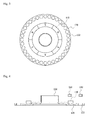
- FIG. 3 is a view illustrating a sensing magnet 110 and a sensing plate 120, according to another embodiment of the present invention.
- FIG. 4 is a partial cross-sectional view illustrating a motor including the sensing magnet 110 and the sensing plate 120 of FIG. 3 .
- the sensing magnet 110 includes main poles that are arranged adjacent to a through-hole in a circumferential direction.
- the main poles include a plurality of poles that are arranged to correspond to those of a drive magnet that is inserted into a rotor (not shown) of the motor. That is, the drive magnet is configured such that N poles and S poles are alternately arranged around the rotor, and a plurality of poles of the sensing magnet 110 are arranged to correspond to the N poles and the S poles of the drive magnet.
- the sensing magnet 110 is mounted on the sensing plate 120, and a plurality of holes 122 are formed along with an edge of the sensing plate 120.
- the number of the holes 122 is greater than the number of the N poles or the S poles of the sensing magnet 110.
- the sensing magnet 110 is mounted on the sensing plate 120, and the sensing plate 120 surrounds a rotating shaft 130.
- the rotor that rotates along with the rotating shaft 130 and includes the drive magnet surrounds the rotating shaft 130, and the sensing plate 120 is disposed over the rotor.
- Sensors 140 and 150 that respectively detect a change in the sensing plate 120 and the sensing magnet 110 are respectively disposed over the sensing plate 120 and the sensing magnet 110.
- the sensing magnet 110, the sensing plate 120, and the sensors 140 and 150 may be collectively referred to as a sensing unit.
- the sensing magnet 110 is disposed closer to the rotating shaft 130 than the holes that are formed in the sensing plate 120.
- the sensor 140 is disposed over the holes 122 that are formed in the sensing plate 120, and detects a change in the sensing plate 120.
- the sensor 140 may be an optical sensor that detects light passing through the holes 122.
- the optical sensor may be, for example, a tachometer.
- the sensor 150 is disposed over the sensing magnet 110, and detects a change in a magnetic flux of the sensing magnet 110.
- the sensor 150 may be a Hall IC.
- the plurality of holes 122 formed in the sensing plate 120 function as the FG poles 3 of the sensing magnet 10 of FIG. 1 . Accordingly, a rotation angle of the motor may be accurately measured while preventing magnetic flux interference between main poles and FG poles.
- waveform distortion due to magnetic flux interference may be prevented by removing the sensing magnet 110.
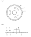
- FIG. 5 is a view illustrating a sensing plate 220 according to another embodiment of the present invention.
- FIG. 6 is a partial cross-sectional view illustrating a motor including the sensing plate 220 of FIG. 5 .
- the sensing plate 220 has a through-hole through which a rotating shaft 230 may pass, and has a disk shape.
- a plurality of holes 222 are formed along with an edge of the sensing plate 220.
- a plurality of holes 224 are formed closer to the rotating shaft 230 than the holes 222 in a circumferential direction to surround the rotating shaft 230.
- the holes 224 are formed to correspond to poles of a drive magnet that is inserted into a rotor of the motor. That is, the drive magnet is configured such that N poles and S poles are alternately arranged around the rotor, and the holes 224 are arranged to correspond to the N poles or the S poles of the drive magnet.
- the number of the holes 222 may be greater than the number of the holes 224.
- the sensing plate 220 surrounds the rotating shaft 230.
- the rotor that rotates along with the rotating shaft 230 and includes the drive magnet surrounds the rotating shaft 230, and the sensing plate 220 is disposed over the rotor.
- Sensors 240 and 250 that detect a change in the sensing plate 220 are respectively disposed over the holes 222 and 224 of the sensing plate 220.
- the sensing plate 220 and the sensors 240 and 250 may be collectively referred to as a sensing unit.
- the sensor 240 is disposed over the holes 222 that are formed along with the edge of the sensing plate 220, and detects a change in the sensing plate 220.
- the sensor 250 is disposed over the holes 224 that are formed closer to the rotating shaft 230 than the holes 222 to surround the rotating shaft 230, and detects a change in the sensing plate 220.
- the sensors 240 and 250 may be optical sensors that detect light passing through the holes 222 and 224.
- the optical sensors may be, for example, tachometers.
- the holes 222 that are formed in the sensing plate 220 may function as the FG poles 3 of the sensing magnet 10 of FIG. 1
- the holes 224 may function as the main poles 2 of the sensing magnet 10 of FIG. 1 . Accordingly, a rotation angle of the motor may be accurately measured while preventing magnetic flux interference between main poles and FG poles.
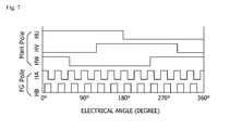
- FIG. 7 is a graph illustrating a waveform output from a sensing unit, according to an embodiment of the present invention.
- a Hall IC for the sensing magnet 110 may output 1 (On) at N poles and may output 0 (Off) at S poles, and an optical sensor for holes of the sensing plate 120 may output 1 (On) when light is reflected and may output 0 (Off) when light is not reflected.
- an optical sensor for holes of the sensing plate 120 may output 1 (On) when light is reflected and may output 0 (Off) when light is not reflected.
- an optical sensor for holes (corresponding to main poles) formed on an inner race of the sensing plate 220 and an optical sensor for holes (corresponding to FG poles) formed on an outer race of the sensing plate 220 may output 1 (On) when light is reflected and may output 0 (Off) when light is not reflected.
- rotation of the motor may be detected with the same detection effect as that obtained by using a magnet and a Hall IC while preventing waveform distortion.
- waveform distortion due to interference between main poles and FG poles of a sensing magnet may be prevented. Costs may be reduced by entirely or partially removing the sensing magnet.
Landscapes
- Engineering & Computer Science (AREA)
- Power Engineering (AREA)
- Microelectronics & Electronic Packaging (AREA)
- Physics & Mathematics (AREA)
- General Physics & Mathematics (AREA)
- Transmission And Conversion Of Sensor Element Output (AREA)
Abstract
Description
- This application claims priority to and the benefit of Korean Patent Application No.
2012-0147320, filed on December 17, 2012 - The present invention relates to a motor, and more particularly, to a sensing unit of a motor.
- In general, a motor includes a rotating shaft, a rotor that surrounds the rotating shaft, a stator that is spaced a predetermined interval from the rotor, and a housing that fixes the stator.
- The rotating shaft may be supported by the housing. The rotor includes a rotor core that surrounds the rotating shaft and a drive magnet that is coupled to the rotor core. The stator includes a plurality of stator cores and coils that are wound around each of the stator cores. When current is applied to the stator, the rotor rotates due to interaction between the stator and the rotor.
- The motor may include a sensor and a sensing magnet for detecting the amount of rotation of the motor. The sensing magnet is generally magnetized on an inner race, and includes main poles that are arranged to correspond to those of the drive magnet and frequency generator (FG) poles that are magnetized on an outer race and are arranged more densely than the main poles.
- Accordingly, a rotation angle of the motor may be accurately measured, and the motor may be softly driven. However, magnetic flux interference between the main poles and the FG poles may occur, thereby leading to waveform distortion.
- Although a dummy track may be disposed between the main poles and the FG poles, there is a limitation on a size of the sensing magnet, and thus it is difficult to secure sufficient space for the dummy track.
- The present invention is directed to a structure of a sensing unit of a motor.
- According to an aspect of the present invention, there is provided a motor including: a rotating shaft; a rotor that surrounds the rotating shaft, rotates along with the rotating shaft, and includes a drive magnet; and a sensing unit that surrounds the rotating shaft, is disposed over the rotor, and detects rotation of the rotor, wherein the sensing unit includes: a sensing plate that includes a plurality of holes that are formed along with an edge of the sensing plate; a sensing magnet that is mounted on the sensing plate and is disposed closer to the rotating shaft than the plurality of holes; a first sensor that is disposed over the sensing plate and detects a change in the sensing plate; and a second sensor that is disposed over the sensing magnet and detects a change in the sensing magnet.
- The first sensor may be an optical sensor, and the second sensor may be a Hall integration chip (IC).
- The drive magnet may be configured such that N poles and S poles are alternately arranged around the rotor, and the sensing magnet may include a plurality of poles that are arranged to correspond to poles of the drive magnet.
- A number of the plurality of holes of the sensing plate may be greater than a number ofN poles or S poles of the sensing magnet.
- According to another aspect of the present invention, there is provided a motor including: a rotating shaft; a rotor that surrounds the rotating shaft, rotates along with the rotating shaft, and includes a drive magnet; and a sensing unit that surrounds the rotating shaft, is disposed over the rotor, and detects rotation of the rotor, wherein the sensing unit includes: a sensing plate that includes a plurality of first holes that are formed along with an edge of the sensing plate and a plurality of second holes that are formed closer to the rotating shaft than the plurality of first holes to surround the rotating shaft; and first and second sensors that are respectively disposed over the plurality of first and second holes and detect a change in the sensing plate.
- The first and second sensors may be optical sensors.
- The drive magnet may be configured such that N poles and S poles are alternately arranged around the rotor, wherein the plurality of second hole are formed to correspond to the N poles or S poles of the drive magnet.
- A number of the plurality of first holes may be greater than a number of the plurality of second holes.
- According to another aspect of the present invention, there is provided a sensing unit including: a sensing plate that surrounds a rotating shaft and includes a plurality of holes that are formed includes edge of the sensing plate; a sensing magnet that is mounted on the sensing plate and is disposed closer to the rotating shaft than the plurality of holes; a first sensor that is disposed over the sensing plate and detects a change in the sensing plate; and a second sensor that is disposed over the sensing magnet and detects a change in the sensing magnet.
- According to another aspect of the present invention, there is provided a sensing unit including: a sensing plate that surrounds a rotating shaft and includes a plurality of first holes that are formed along with an edge of the sensing plate and a plurality of second holes that are formed closer to the rotating shaft than the plurality of first holes to surround the rotating shaft; and first and second sensors that are respectively disposed over the plurality of first and second holes and detect a change in the sensing plate.
- The above and other objects, features and advantages of the present invention will become more apparent to those of ordinary skill in the art by describing in detail exemplary embodiments thereof with reference to the accompanying drawings, in which:
-
FIG. 1 is a view illustrating a sensing magnet according to an embodiment of the present invention; -
FIG. 2 is a partial cross-sectional view illustrating a motor on which the sensing magnet ofFIG. 1 is magnetized; -
FIG. 3 is a view illustrating a sensing magnet and a sensing plate according to another embodiment of the present invention; -
FIG. 4 is a partial cross-sectional view illustrating a motor including the sensing magnet and the sensing plate ofFIG. 3 ; -
FIG. 5 is a view illustrating a sensing plate according to another embodiment of the present invention; -
FIG. 6 is a partial cross-sectional view illustrating a motor including the sensing plate ofFIG. 5 ; and -
FIG. 7 is a graph illustrating a waveform output from a sensing unit, according to an embodiment of the present invention. - As the invention allows for various changes and numerous embodiments, particular embodiments will be illustrated in the drawings and described in detail in the written description. However, this is not intended to limit the present invention to particular modes of practice, and it is to be appreciated that all changes, equivalents, and substitutes that do not depart from the spirit and technical scope of the present invention are encompassed in the present invention.
- It will be understood that, although the terms first, second, third etc. may be used herein to describe various elements, these elements should not be limited by these terms. These terms are only used to distinguish one element from another element. Thus, a first element discussed below could be termed a second element and, similarly, a second element could be termed a first element without departing from the teachings of exemplary embodiments. As used herein, the term "and/or," includes any and all combinations of one or more of the associated listed items.
- It will be understood that when an element is referred to as being "on", "connected to" or "coupled to" another element, it may be directly on, connected or coupled to the other element or intervening elements may be present. In contrast, when an element is referred to as being "directly on," "directly connected to" or "directly coupled to" another element, there are no intervening elements.
- The terminology used herein is for the purpose of describing particular embodiments only and is not intended to be limiting of exemplary embodiments. As used herein, the singular forms "a," "an," and "the," are intended to include the plural forms as well, unless the context clearly indicates otherwise. It will be further understood that the terms "comprises," "comprising," "includes," and/or "including," when used herein, specify the presence of stated features, integers, steps, operations, elements, components, or combinations thereof, but do not preclude the presence or addition of one or more other features, integers, steps, operations, elements, components, or combinations thereof.
- Unless otherwise defined, all terms (including technical and scientific terms) used herein have the same meaning as commonly understood by one of ordinary skill in the art to which exemplary embodiments belong. It will be further understood that terms, such as those defined in commonly used dictionaries, should be interpreted as having a meaning that is consistent with their meaning in the context of the relevant art and will not be interpreted in an idealized or overly formal sense unless expressly so defined herein.
- The present invention will now be described more fully with reference to the accompanying drawings, in which exemplary embodiments of the present invention are shown. In the drawings, the same elements are denoted by the same reference numerals and a repeated explanation thereof will not be given.
-
FIG. 1 is a view illustrating asensing magnet 10.FIG. 2 is a partial cross-sectional view illustrating a motor on which thesensing magnet 1 ofFIG. 1 is magnetized. - Referring to
FIG. 1 , thesensing magnet 10 has a disk shape, and a through-hole 1 through which a rotatingshaft 30 may pass is formed in a central portion of thesensing magnet 10. - The
sensing magnet 10 includesmain poles 2 that are arranged adjacent to the through-hole 1 in a circumferential direction and frequency generator (FG)poles 3 that are formed on an edge of thesensing magnet 10. - The
main poles 2 include a plurality of poles that are arranged to correspond to those of a drive magnet that is inserted into a rotor of the motor. TheFG poles 3 are arranged more densely than themain poles 2 and thus include more poles than themain poles 2. Accordingly, a rotation angle may be more accurately separately measured, and the motor may be more softly driven. - Referring to
FIGS. 1 and 2 , thesensing magnet 10 is mounted on thesensing plate 20, and thesensing plate 20 surrounds the rotatingshaft 30. Although not shown inFIGS. 1 and 2 , thesensing plate 20 is disposed over the rotor that surrounds the rotatingshaft 30 and rotates along with the rotatingshaft 30. - Hall integration chips (ICs) 40 and 50 are respectively disposed over the
FG poles 3 that correspond to an outer race of thesensing magnet 10 and themain poles 2 that correspond to an inner race of thesensing magnet 10, and detect a change in a magnetic flux as thesensing magnet 10 rotates. TheHall ICs - In this structure, magnetic flux interference occurs between the
main poles 2 and theFG poles 3, thereby leading to waveform distortion. Although magnetic flux interference may be reduced by disposing a dummy track 4 between themain poles 2 and theFG poles 3, there is a limitation on a size of thesensing magnet 10, and thus it is difficult to secure sufficient space for the dummy track 4. - Alternatively, waveform distortion due to magnetic flux interference may be prevented by removing the
FG poles 3 that correspond to the outer race of thesensing magnet 10. -
FIG. 3 is a view illustrating asensing magnet 110 and asensing plate 120, according to another embodiment of the present invention.FIG. 4 is a partial cross-sectional view illustrating a motor including thesensing magnet 110 and thesensing plate 120 ofFIG. 3 . - Referring to
FIG. 3 , thesensing magnet 110 includes main poles that are arranged adjacent to a through-hole in a circumferential direction. The main poles include a plurality of poles that are arranged to correspond to those of a drive magnet that is inserted into a rotor (not shown) of the motor. That is, the drive magnet is configured such that N poles and S poles are alternately arranged around the rotor, and a plurality of poles of thesensing magnet 110 are arranged to correspond to the N poles and the S poles of the drive magnet. - The
sensing magnet 110 is mounted on thesensing plate 120, and a plurality ofholes 122 are formed along with an edge of thesensing plate 120. The number of theholes 122 is greater than the number of the N poles or the S poles of thesensing magnet 110. - Referring to
FIGS. 3 and 4 , thesensing magnet 110 is mounted on thesensing plate 120, and thesensing plate 120 surrounds arotating shaft 130. The rotor that rotates along with therotating shaft 130 and includes the drive magnet surrounds therotating shaft 130, and thesensing plate 120 is disposed over the rotor.Sensors sensing plate 120 and thesensing magnet 110 are respectively disposed over thesensing plate 120 and thesensing magnet 110. - The
sensing magnet 110, thesensing plate 120, and thesensors - The
sensing magnet 110 is disposed closer to therotating shaft 130 than the holes that are formed in thesensing plate 120. - The
sensor 140 is disposed over theholes 122 that are formed in thesensing plate 120, and detects a change in thesensing plate 120. Thesensor 140 may be an optical sensor that detects light passing through theholes 122. The optical sensor may be, for example, a tachometer. - The
sensor 150 is disposed over thesensing magnet 110, and detects a change in a magnetic flux of thesensing magnet 110. To this end, thesensor 150 may be a Hall IC. - As such, the plurality of
holes 122 formed in thesensing plate 120 function as theFG poles 3 of thesensing magnet 10 ofFIG. 1 . Accordingly, a rotation angle of the motor may be accurately measured while preventing magnetic flux interference between main poles and FG poles. - Alternatively, waveform distortion due to magnetic flux interference may be prevented by removing the
sensing magnet 110. -
FIG. 5 is a view illustrating asensing plate 220 according to another embodiment of the present invention.FIG. 6 is a partial cross-sectional view illustrating a motor including thesensing plate 220 ofFIG. 5 . - Referring to
FIG. 5 , thesensing plate 220 has a through-hole through which arotating shaft 230 may pass, and has a disk shape. - A plurality of
holes 222 are formed along with an edge of thesensing plate 220. A plurality ofholes 224 are formed closer to therotating shaft 230 than theholes 222 in a circumferential direction to surround therotating shaft 230. Theholes 224 are formed to correspond to poles of a drive magnet that is inserted into a rotor of the motor. That is, the drive magnet is configured such that N poles and S poles are alternately arranged around the rotor, and theholes 224 are arranged to correspond to the N poles or the S poles of the drive magnet. The number of theholes 222 may be greater than the number of theholes 224. - Referring to
FIGS. 5 and 6 , thesensing plate 220 surrounds therotating shaft 230. Although not shown inFIGS. 5 and 6 , the rotor that rotates along with therotating shaft 230 and includes the drive magnet surrounds therotating shaft 230, and thesensing plate 220 is disposed over the rotor.Sensors sensing plate 220 are respectively disposed over theholes sensing plate 220. - The
sensing plate 220 and thesensors - The
sensor 240 is disposed over theholes 222 that are formed along with the edge of thesensing plate 220, and detects a change in thesensing plate 220. Thesensor 250 is disposed over theholes 224 that are formed closer to therotating shaft 230 than theholes 222 to surround therotating shaft 230, and detects a change in thesensing plate 220. To this end, thesensors holes - As such, the
holes 222 that are formed in thesensing plate 220 may function as theFG poles 3 of thesensing magnet 10 ofFIG. 1 , and theholes 224 may function as themain poles 2 of thesensing magnet 10 ofFIG. 1 . Accordingly, a rotation angle of the motor may be accurately measured while preventing magnetic flux interference between main poles and FG poles. -
FIG. 7 is a graph illustrating a waveform output from a sensing unit, according to an embodiment of the present invention. In the sensing unit ofFIG. 3 , a Hall IC for thesensing magnet 110 may output 1 (On) at N poles and may output 0 (Off) at S poles, and an optical sensor for holes of thesensing plate 120 may output 1 (On) when light is reflected and may output 0 (Off) when light is not reflected. In the sensing unit ofFIG. 5 , an optical sensor for holes (corresponding to main poles) formed on an inner race of thesensing plate 220 and an optical sensor for holes (corresponding to FG poles) formed on an outer race of thesensing plate 220 may output 1 (On) when light is reflected and may output 0 (Off) when light is not reflected. - As such, rotation of the motor may be detected with the same detection effect as that obtained by using a magnet and a Hall IC while preventing waveform distortion.
- According to the one or more embodiments of the present invention, waveform distortion due to interference between main poles and FG poles of a sensing magnet may be prevented. Costs may be reduced by entirely or partially removing the sensing magnet.
- It will be apparent to those skilled in the art that various modifications can be made to the above-described exemplary embodiments of the present invention without departing from the spirit or scope of the invention. Thus, it is intended that the present invention covers all such modifications provided they come within the scope of the appended claims and their equivalents.
Claims (14)
- A motor comprising:a rotating shaft(130);a rotor that surrounds the rotating shaft(130), rotates along with the rotating shaft, and comprises a drive magnet; anda sensing unit that surrounds the rotating shaft(130), is disposed over the rotor, and detects rotation of the rotor,wherein the sensing unit comprises:a sensing plate(120) that comprises a plurality of holes(122) that are formed along with an edge of the sensing plate(120);a sensing magnet(110) that is mounted on the sensing plate(120) and is disposed closer to the rotating shaft(130) than the plurality ofholes(122);a first sensor(140) that is disposed over the sensing plate(120) and detects a change in the sensing plate(120); anda second sensor(150) that is disposed over the sensing magnet(110) and detects a change in the sensing magnet(110).
- The motor of claim 1, wherein the first sensor(140) is an optical sensor, and the second sensor(150) is a Hall integration chip (IC).
- The motor of claim 1, wherein the drive magnet is configured such that N poles and S poles are alternately arranged around the rotor, and
the sensing magnet(110) comprises a plurality of poles that are arranged to correspond to poles of the drive magnet. - The motor of claim 3, wherein the number of the plurality of holes(122) of the sensing plate(120) is greater than the number of N poles or S poles of the sensing magnet(110).
- A motor comprising:a rotating shaft(230);a rotor that surrounds the rotating shaft(230), rotates along with the rotating shaft(230), and comprises a drive magnet; anda sensing unit that surrounds the rotating shaft(230), is disposed over the rotor, and detects rotation of the rotor,wherein the sensing unit comprises:a sensing plate(220) that comprises a plurality of first holes(222) that are formed along with an edge of the sensing plate(220), and a plurality of second holes(224) that are formed closer to the rotating shaft(230) than the plurality of first holes(222) to surround the rotating shaft(230); andfirst and second sensors(240, 250) that are respectively disposed over the plurality of first and second holes(222, 224) and detect a change in the sensing plate(220).
- The motor of claim 5, wherein the first and second sensors(240, 250) are optical sensors.
- The motor of claim 5, wherein the drive magnet is configured such that N poles and S poles are alternately arranged around the rotor,
wherein the plurality of second holes(224) are formed to correspond to the N poles or S poles of the drive magnet. - The motor of claim 5, wherein the number of the plurality of first holes(222) is greater than the number of the plurality of second holes(224).
- A sensing unit comprising:a sensing plate(120) that surrounds a rotating shaft(130) and comprises a plurality of holes(122) that are formed along with an edge of the sensing plate(120);a sensing magnet(110) that is mounted on the sensing plate(120) and is disposed closer to the rotating shaft(130) than the plurality ofholes(122);a first sensor(140) that is disposed over the sensing plate(120) and detects a change in the sensing plate(120); anda second sensor(150) that is disposed over the sensing magnet(110) and detects a change in the sensing magnet(110).
- The sensing unit of claim 9, wherein the first sensor(140) is an optical sensor, and the second sensor(150) is a Hall integration chip (IC).
- The sensing unit of claim 9, wherein the number of the plurality of holes(122) of the sensing plate(120) is greater than the number of N poles or S poles of the sensing magnet.
- A sensing unit comprising:a sensing plate(220) that surrounds a rotating shaft(230) and comprises a plurality of first holes(222) that are formed along with an edge of the sensing plate(220) and a plurality of second holes(224) that are formed closer to the rotating shaft(230) than the plurality of first holes(222) to surround the rotating shaft(230); andfirst and second sensors(240, 250) that are respectively disposed over the plurality of first and second holes(222, 224) and detect a change in the sensing plate(220).
- The sensing unit of claim 12, wherein the first and second sensors(240, 250) are optical sensors.
- The sensing unit of claim 12, wherein the number of the plurality of first holes(222) is greater than the number of the plurality of second holes(224).
Applications Claiming Priority (1)
| Application Number | Priority Date | Filing Date | Title |
|---|---|---|---|
| KR1020120147320A KR101987169B1 (en) | 2012-12-17 | 2012-12-17 | Motor |
Publications (3)
| Publication Number | Publication Date |
|---|---|
| EP2744088A2 true EP2744088A2 (en) | 2014-06-18 |
| EP2744088A3 EP2744088A3 (en) | 2017-07-19 |
| EP2744088B1 EP2744088B1 (en) | 2021-10-13 |
Family
ID=49766961
Family Applications (1)
| Application Number | Title | Priority Date | Filing Date |
|---|---|---|---|
| EP13197223.4A Not-in-force EP2744088B1 (en) | 2012-12-17 | 2013-12-13 | Motor |
Country Status (5)
| Country | Link |
|---|---|
| US (1) | US9995599B2 (en) |
| EP (1) | EP2744088B1 (en) |
| JP (1) | JP6385672B2 (en) |
| KR (1) | KR101987169B1 (en) |
| CN (1) | CN103872853A (en) |
Cited By (1)
| Publication number | Priority date | Publication date | Assignee | Title |
|---|---|---|---|---|
| CN106969786A (en) * | 2017-04-24 | 2017-07-21 | 上海市雷智电机有限公司 | A kind of encoder and its installation method |
Families Citing this family (21)
| Publication number | Priority date | Publication date | Assignee | Title |
|---|---|---|---|---|
| EP2549631B1 (en) * | 2011-07-22 | 2021-07-14 | LG Innotek Co., Ltd. | Holding structure of sensing magnet for EPS motor |
| JP6209486B2 (en) * | 2014-05-13 | 2017-10-04 | 双葉電子工業株式会社 | Angle detection device and servo device using the angle detection device |
| KR102491102B1 (en) * | 2015-10-28 | 2023-01-20 | 엘지이노텍 주식회사 | Detecting device for sensing the rotor position and motor having the same |
| US20170191851A1 (en) * | 2015-12-15 | 2017-07-06 | Mts Sensor Technologie Gmbh & Co. Kg | Position sensing system |
| KR102542138B1 (en) * | 2016-01-07 | 2023-06-12 | 엘지이노텍 주식회사 | Detecting device for sensing the rotor position and motor having the same |
| KR102146023B1 (en) * | 2016-01-07 | 2020-08-19 | 엘지이노텍 주식회사 | Motor and electronic power steering system having the same |
| FR3051083B1 (en) * | 2016-05-04 | 2018-04-27 | Valeo Systemes De Controle Moteur | MAGNETIC COMPONENT FOR A HALL EFFECT SENSOR, ELECTRICAL ASSEMBLY AND ELECTRICAL POWER COMPRESSOR COMPRISING SUCH A MAGNETIC COMPONENT |
| CN111355345B (en) * | 2016-09-05 | 2021-09-07 | Lg伊诺特有限公司 | Apparatus for sensing rotor position and motor including the same |
| KR102101177B1 (en) * | 2016-09-05 | 2020-05-29 | 엘지이노텍 주식회사 | Detecting device for sensing the rotor position and motor having the same |
| KR102516544B1 (en) * | 2017-11-13 | 2023-03-31 | 엘지이노텍 주식회사 | Sensing stator and motor having the same |
| WO2018135805A1 (en) * | 2017-01-19 | 2018-07-26 | 엘지이노텍 주식회사 | Sensing magnet assembly, rotor position sensing apparatus, and motor including same |
| JP6904803B2 (en) * | 2017-06-23 | 2021-07-21 | 日本電産サンキョー株式会社 | motor |
| JP7006107B2 (en) * | 2017-10-04 | 2022-01-24 | 株式会社デンソー | Motor control device |
| JP7255099B2 (en) * | 2018-07-09 | 2023-04-11 | 株式会社デンソー | motor |
| DE102018117600A1 (en) * | 2018-07-20 | 2020-01-23 | Fraba B.V. | Rotation angle measuring system |
| KR102741581B1 (en) * | 2019-03-12 | 2024-12-12 | 에이치엘만도 주식회사 | Motor position sensor |
| KR102896996B1 (en) * | 2019-12-18 | 2025-12-08 | 엘지이노텍 주식회사 | Motor |
| CN112117937B (en) * | 2020-09-08 | 2021-12-31 | 绍兴文理学院元培学院 | Permanent magnet synchronous motor control system and motor rotating speed measuring method |
| CN115224881B (en) * | 2021-04-16 | 2026-01-23 | 贺欣机械厂股份有限公司 | Rotation shaft sensing device of sewing machine motor |
| CN113726101A (en) * | 2021-09-24 | 2021-11-30 | 深圳市灵犀自动化技术有限公司 | Encoder, motor and driving system |
| KR102553716B1 (en) * | 2022-12-29 | 2023-07-10 | 유미희 | Motor state detection system in which the magnet and magnetic switch are located on two different planes |
Family Cites Families (20)
| Publication number | Priority date | Publication date | Assignee | Title |
|---|---|---|---|---|
| US4358735A (en) * | 1977-07-25 | 1982-11-09 | Sps Technologies, Inc. | Bidirectional incremental encoding system for measuring maximum forward angular displacement of a bidirectionally rotatable rotating shaft |
| JPS59127557A (en) | 1982-12-29 | 1984-07-23 | Matsushita Electric Works Ltd | Optically detecting device of rotating amount of motor |
| JPS60176439A (en) * | 1984-02-23 | 1985-09-10 | Matsushita Electric Ind Co Ltd | Electric motor |
| JPH0382359A (en) * | 1989-08-23 | 1991-04-08 | Hitachi Ltd | Brushless DC motor with encoder |
| US5223183A (en) | 1992-04-02 | 1993-06-29 | Uop | Baffled downcomer fractionation tray |
| DE4243778A1 (en) * | 1992-12-23 | 1994-06-30 | Bosch Gmbh Robert | Position detection method, e.g. for vehicle steering wheel angle |
| US5631508A (en) * | 1993-07-27 | 1997-05-20 | Mitsumi Electric Co., Ltd. | Cost-saving, small-sized motor with improved stability over wide speed range |
| JPH0829201A (en) * | 1994-07-18 | 1996-02-02 | Nikon Corp | Multi-turn absolute encoder |
| JPH08205479A (en) | 1995-01-30 | 1996-08-09 | Oriental Motor Co Ltd | Securing method for rotary disc in rotary encoder |
| US5900709A (en) * | 1996-02-23 | 1999-05-04 | Konica Corporation | Rotation control device |
| US5717268A (en) * | 1996-06-17 | 1998-02-10 | Philips Electronics North America Corp. | Electric motor with tachometer signal generator |
| JP4150133B2 (en) | 1999-07-09 | 2008-09-17 | 日本サーボ株式会社 | Multipolar rotating electrical machine and its sensing method |
| CN1210860C (en) * | 1999-07-16 | 2005-07-13 | 松下电器产业株式会社 | Permanent magnet synchronous motor |
| JP3757118B2 (en) * | 2001-01-10 | 2006-03-22 | 株式会社日立製作所 | Non-contact rotational position sensor and throttle valve assembly having non-contact rotational position sensor |
| JP2007135258A (en) * | 2005-11-08 | 2007-05-31 | Iai:Kk | Stepping motor controller and actuator |
| JP2007202382A (en) | 2005-12-28 | 2007-08-09 | Mabuchi Motor Co Ltd | Optical encoder of small motor and its manufacturing process |
| DE102009020570B4 (en) * | 2009-05-08 | 2012-06-14 | Ic - Haus Gmbh | Monolithic integrated sensor circuit and material testing apparatus comprising this circuit |
| JP5126290B2 (en) * | 2010-06-07 | 2013-01-23 | 株式会社安川電機 | Encoder, servo motor, servo unit, and encoder manufacturing method |
| JP2014013163A (en) | 2012-07-04 | 2014-01-23 | Yaskawa Electric Corp | Encoder, and motor |
| JP6278622B2 (en) * | 2012-07-31 | 2018-02-14 | キヤノン株式会社 | Motor control device and motor control method |
-
2012
- 2012-12-17 KR KR1020120147320A patent/KR101987169B1/en active Active
-
2013
- 2013-12-13 EP EP13197223.4A patent/EP2744088B1/en not_active Not-in-force
- 2013-12-17 CN CN201310693742.2A patent/CN103872853A/en active Pending
- 2013-12-17 US US14/109,147 patent/US9995599B2/en active Active
- 2013-12-17 JP JP2013259864A patent/JP6385672B2/en active Active
Non-Patent Citations (1)
| Title |
|---|
| None |
Cited By (1)
| Publication number | Priority date | Publication date | Assignee | Title |
|---|---|---|---|---|
| CN106969786A (en) * | 2017-04-24 | 2017-07-21 | 上海市雷智电机有限公司 | A kind of encoder and its installation method |
Also Published As
| Publication number | Publication date |
|---|---|
| US9995599B2 (en) | 2018-06-12 |
| JP2014121266A (en) | 2014-06-30 |
| CN103872853A (en) | 2014-06-18 |
| JP6385672B2 (en) | 2018-09-05 |
| KR101987169B1 (en) | 2019-06-10 |
| US20140167743A1 (en) | 2014-06-19 |
| KR20140078796A (en) | 2014-06-26 |
| EP2744088A3 (en) | 2017-07-19 |
| EP2744088B1 (en) | 2021-10-13 |
Similar Documents
| Publication | Publication Date | Title |
|---|---|---|
| EP2744088A2 (en) | Motor | |
| JP7006107B2 (en) | Motor control device | |
| US20060108881A1 (en) | Electric machine, particularly a brushless direct current motor | |
| US11799365B2 (en) | Sensing apparatus, rotor, and method for determining presence of abnormality in sensor | |
| US10069383B2 (en) | Electronically commuted electric motor with direct sampling of the magnetic field of the rotor | |
| KR102499547B1 (en) | Motor | |
| US20210135546A1 (en) | Brushless Electrical Machine | |
| CN102654385A (en) | Sensor arrangement | |
| US20170167897A1 (en) | Angle measurement device and electric motor | |
| JP7205488B2 (en) | Motors and electrical equipment containing the motors | |
| CN104246441A (en) | Device for detecting angular position of shaft of windscreen wiper motor using magnetoresitive sensor | |
| CN203811188U (en) | Magnetic rotation encoder | |
| CN105745824A (en) | Starter generator with engine control signal output function | |
| US20140001997A1 (en) | Motor and method of measuring and controlling distance of air gap between rotor and stator assembly | |
| EP2830199A2 (en) | Rotating electric machine and saddle-ride type vehicle | |
| KR20100138163A (en) | Rotor position detecting device and brushless motor having same | |
| CN108370202B (en) | Sensor arrangement in an electric machine | |
| CN113632341A (en) | Motor | |
| EP3402056B1 (en) | Device for detecting position of rotor, and motor comprising same | |
| CN106662469B (en) | motor | |
| CN112970175B (en) | electric motor | |
| JP4877599B2 (en) | SR motor rotation angle detection device | |
| EP4135171A1 (en) | Single phase brushless dc motor | |
| CN112865435A (en) | Motor vehicle and sensor thereof | |
| JP3071958U (en) | Rotary drum motor rotation position detector |
Legal Events
| Date | Code | Title | Description |
|---|---|---|---|
| PUAI | Public reference made under article 153(3) epc to a published international application that has entered the european phase |
Free format text: ORIGINAL CODE: 0009012 |
|
| 17P | Request for examination filed |
Effective date: 20140331 |
|
| AK | Designated contracting states |
Kind code of ref document: A2 Designated state(s): AL AT BE BG CH CY CZ DE DK EE ES FI FR GB GR HR HU IE IS IT LI LT LU LV MC MK MT NL NO PL PT RO RS SE SI SK SM TR |
|
| AX | Request for extension of the european patent |
Extension state: BA ME |
|
| RAP1 | Party data changed (applicant data changed or rights of an application transferred) |
Owner name: LG INNOTEK CO., LTD. |
|
| PUAL | Search report despatched |
Free format text: ORIGINAL CODE: 0009013 |
|
| AK | Designated contracting states |
Kind code of ref document: A3 Designated state(s): AL AT BE BG CH CY CZ DE DK EE ES FI FR GB GR HR HU IE IS IT LI LT LU LV MC MK MT NL NO PL PT RO RS SE SI SK SM TR |
|
| AX | Request for extension of the european patent |
Extension state: BA ME |
|
| RIC1 | Information provided on ipc code assigned before grant |
Ipc: H02K 11/00 20160101AFI20170609BHEP |
|
| STAA | Information on the status of an ep patent application or granted ep patent |
Free format text: STATUS: EXAMINATION IS IN PROGRESS |
|
| 17Q | First examination report despatched |
Effective date: 20190626 |
|
| GRAP | Despatch of communication of intention to grant a patent |
Free format text: ORIGINAL CODE: EPIDOSNIGR1 |
|
| STAA | Information on the status of an ep patent application or granted ep patent |
Free format text: STATUS: GRANT OF PATENT IS INTENDED |
|
| INTG | Intention to grant announced |
Effective date: 20210503 |
|
| GRAS | Grant fee paid |
Free format text: ORIGINAL CODE: EPIDOSNIGR3 |
|
| GRAA | (expected) grant |
Free format text: ORIGINAL CODE: 0009210 |
|
| STAA | Information on the status of an ep patent application or granted ep patent |
Free format text: STATUS: THE PATENT HAS BEEN GRANTED |
|
| AK | Designated contracting states |
Kind code of ref document: B1 Designated state(s): AL AT BE BG CH CY CZ DE DK EE ES FI FR GB GR HR HU IE IS IT LI LT LU LV MC MK MT NL NO PL PT RO RS SE SI SK SM TR |
|
| REG | Reference to a national code |
Ref country code: GB Ref legal event code: FG4D |
|
| REG | Reference to a national code |
Ref country code: CH Ref legal event code: EP |
|
| REG | Reference to a national code |
Ref country code: DE Ref legal event code: R096 Ref document number: 602013079624 Country of ref document: DE |
|
| REG | Reference to a national code |
Ref country code: IE Ref legal event code: FG4D |
|
| REG | Reference to a national code |
Ref country code: AT Ref legal event code: REF Ref document number: 1438890 Country of ref document: AT Kind code of ref document: T Effective date: 20211115 |
|
| REG | Reference to a national code |
Ref country code: NL Ref legal event code: FP |
|
| REG | Reference to a national code |
Ref country code: LT Ref legal event code: MG9D |
|
| REG | Reference to a national code |
Ref country code: DE Ref legal event code: R082 Ref document number: 602013079624 Country of ref document: DE |
|
| REG | Reference to a national code |
Ref country code: AT Ref legal event code: MK05 Ref document number: 1438890 Country of ref document: AT Kind code of ref document: T Effective date: 20211013 |
|
| PG25 | Lapsed in a contracting state [announced via postgrant information from national office to epo] |
Ref country code: RS Free format text: LAPSE BECAUSE OF FAILURE TO SUBMIT A TRANSLATION OF THE DESCRIPTION OR TO PAY THE FEE WITHIN THE PRESCRIBED TIME-LIMIT Effective date: 20211013 Ref country code: LT Free format text: LAPSE BECAUSE OF FAILURE TO SUBMIT A TRANSLATION OF THE DESCRIPTION OR TO PAY THE FEE WITHIN THE PRESCRIBED TIME-LIMIT Effective date: 20211013 Ref country code: FI Free format text: LAPSE BECAUSE OF FAILURE TO SUBMIT A TRANSLATION OF THE DESCRIPTION OR TO PAY THE FEE WITHIN THE PRESCRIBED TIME-LIMIT Effective date: 20211013 Ref country code: BG Free format text: LAPSE BECAUSE OF FAILURE TO SUBMIT A TRANSLATION OF THE DESCRIPTION OR TO PAY THE FEE WITHIN THE PRESCRIBED TIME-LIMIT Effective date: 20220113 Ref country code: AT Free format text: LAPSE BECAUSE OF FAILURE TO SUBMIT A TRANSLATION OF THE DESCRIPTION OR TO PAY THE FEE WITHIN THE PRESCRIBED TIME-LIMIT Effective date: 20211013 |
|
| PG25 | Lapsed in a contracting state [announced via postgrant information from national office to epo] |
Ref country code: IS Free format text: LAPSE BECAUSE OF FAILURE TO SUBMIT A TRANSLATION OF THE DESCRIPTION OR TO PAY THE FEE WITHIN THE PRESCRIBED TIME-LIMIT Effective date: 20220213 Ref country code: SE Free format text: LAPSE BECAUSE OF FAILURE TO SUBMIT A TRANSLATION OF THE DESCRIPTION OR TO PAY THE FEE WITHIN THE PRESCRIBED TIME-LIMIT Effective date: 20211013 Ref country code: PT Free format text: LAPSE BECAUSE OF FAILURE TO SUBMIT A TRANSLATION OF THE DESCRIPTION OR TO PAY THE FEE WITHIN THE PRESCRIBED TIME-LIMIT Effective date: 20220214 Ref country code: PL Free format text: LAPSE BECAUSE OF FAILURE TO SUBMIT A TRANSLATION OF THE DESCRIPTION OR TO PAY THE FEE WITHIN THE PRESCRIBED TIME-LIMIT Effective date: 20211013 Ref country code: NO Free format text: LAPSE BECAUSE OF FAILURE TO SUBMIT A TRANSLATION OF THE DESCRIPTION OR TO PAY THE FEE WITHIN THE PRESCRIBED TIME-LIMIT Effective date: 20220113 Ref country code: LV Free format text: LAPSE BECAUSE OF FAILURE TO SUBMIT A TRANSLATION OF THE DESCRIPTION OR TO PAY THE FEE WITHIN THE PRESCRIBED TIME-LIMIT Effective date: 20211013 Ref country code: HR Free format text: LAPSE BECAUSE OF FAILURE TO SUBMIT A TRANSLATION OF THE DESCRIPTION OR TO PAY THE FEE WITHIN THE PRESCRIBED TIME-LIMIT Effective date: 20211013 Ref country code: GR Free format text: LAPSE BECAUSE OF FAILURE TO SUBMIT A TRANSLATION OF THE DESCRIPTION OR TO PAY THE FEE WITHIN THE PRESCRIBED TIME-LIMIT Effective date: 20220114 Ref country code: ES Free format text: LAPSE BECAUSE OF FAILURE TO SUBMIT A TRANSLATION OF THE DESCRIPTION OR TO PAY THE FEE WITHIN THE PRESCRIBED TIME-LIMIT Effective date: 20211013 |
|
| REG | Reference to a national code |
Ref country code: DE Ref legal event code: R097 Ref document number: 602013079624 Country of ref document: DE |
|
| PG25 | Lapsed in a contracting state [announced via postgrant information from national office to epo] |
Ref country code: SM Free format text: LAPSE BECAUSE OF FAILURE TO SUBMIT A TRANSLATION OF THE DESCRIPTION OR TO PAY THE FEE WITHIN THE PRESCRIBED TIME-LIMIT Effective date: 20211013 Ref country code: SK Free format text: LAPSE BECAUSE OF FAILURE TO SUBMIT A TRANSLATION OF THE DESCRIPTION OR TO PAY THE FEE WITHIN THE PRESCRIBED TIME-LIMIT Effective date: 20211013 Ref country code: RO Free format text: LAPSE BECAUSE OF FAILURE TO SUBMIT A TRANSLATION OF THE DESCRIPTION OR TO PAY THE FEE WITHIN THE PRESCRIBED TIME-LIMIT Effective date: 20211013 Ref country code: MC Free format text: LAPSE BECAUSE OF FAILURE TO SUBMIT A TRANSLATION OF THE DESCRIPTION OR TO PAY THE FEE WITHIN THE PRESCRIBED TIME-LIMIT Effective date: 20211013 Ref country code: EE Free format text: LAPSE BECAUSE OF FAILURE TO SUBMIT A TRANSLATION OF THE DESCRIPTION OR TO PAY THE FEE WITHIN THE PRESCRIBED TIME-LIMIT Effective date: 20211013 Ref country code: DK Free format text: LAPSE BECAUSE OF FAILURE TO SUBMIT A TRANSLATION OF THE DESCRIPTION OR TO PAY THE FEE WITHIN THE PRESCRIBED TIME-LIMIT Effective date: 20211013 Ref country code: CZ Free format text: LAPSE BECAUSE OF FAILURE TO SUBMIT A TRANSLATION OF THE DESCRIPTION OR TO PAY THE FEE WITHIN THE PRESCRIBED TIME-LIMIT Effective date: 20211013 |
|
| REG | Reference to a national code |
Ref country code: CH Ref legal event code: PL |
|
| PLBE | No opposition filed within time limit |
Free format text: ORIGINAL CODE: 0009261 |
|
| STAA | Information on the status of an ep patent application or granted ep patent |
Free format text: STATUS: NO OPPOSITION FILED WITHIN TIME LIMIT |
|
| 26N | No opposition filed |
Effective date: 20220714 |
|
| REG | Reference to a national code |
Ref country code: BE Ref legal event code: MM Effective date: 20211231 |
|
| GBPC | Gb: european patent ceased through non-payment of renewal fee |
Effective date: 20220113 |
|
| PG25 | Lapsed in a contracting state [announced via postgrant information from national office to epo] |
Ref country code: LU Free format text: LAPSE BECAUSE OF NON-PAYMENT OF DUE FEES Effective date: 20211213 Ref country code: IE Free format text: LAPSE BECAUSE OF NON-PAYMENT OF DUE FEES Effective date: 20211213 Ref country code: GB Free format text: LAPSE BECAUSE OF NON-PAYMENT OF DUE FEES Effective date: 20220113 Ref country code: AL Free format text: LAPSE BECAUSE OF FAILURE TO SUBMIT A TRANSLATION OF THE DESCRIPTION OR TO PAY THE FEE WITHIN THE PRESCRIBED TIME-LIMIT Effective date: 20211013 |
|
| PG25 | Lapsed in a contracting state [announced via postgrant information from national office to epo] |
Ref country code: SI Free format text: LAPSE BECAUSE OF FAILURE TO SUBMIT A TRANSLATION OF THE DESCRIPTION OR TO PAY THE FEE WITHIN THE PRESCRIBED TIME-LIMIT Effective date: 20211013 Ref country code: BE Free format text: LAPSE BECAUSE OF NON-PAYMENT OF DUE FEES Effective date: 20211231 |
|
| PG25 | Lapsed in a contracting state [announced via postgrant information from national office to epo] |
Ref country code: LI Free format text: LAPSE BECAUSE OF NON-PAYMENT OF DUE FEES Effective date: 20211231 Ref country code: CH Free format text: LAPSE BECAUSE OF NON-PAYMENT OF DUE FEES Effective date: 20211231 |
|
| PG25 | Lapsed in a contracting state [announced via postgrant information from national office to epo] |
Ref country code: IT Free format text: LAPSE BECAUSE OF FAILURE TO SUBMIT A TRANSLATION OF THE DESCRIPTION OR TO PAY THE FEE WITHIN THE PRESCRIBED TIME-LIMIT Effective date: 20211013 Ref country code: HU Free format text: LAPSE BECAUSE OF FAILURE TO SUBMIT A TRANSLATION OF THE DESCRIPTION OR TO PAY THE FEE WITHIN THE PRESCRIBED TIME-LIMIT; INVALID AB INITIO Effective date: 20131213 |
|
| PG25 | Lapsed in a contracting state [announced via postgrant information from national office to epo] |
Ref country code: CY Free format text: LAPSE BECAUSE OF FAILURE TO SUBMIT A TRANSLATION OF THE DESCRIPTION OR TO PAY THE FEE WITHIN THE PRESCRIBED TIME-LIMIT Effective date: 20211013 |
|
| PGFP | Annual fee paid to national office [announced via postgrant information from national office to epo] |
Ref country code: NL Payment date: 20231121 Year of fee payment: 11 |
|
| PGFP | Annual fee paid to national office [announced via postgrant information from national office to epo] |
Ref country code: FR Payment date: 20231121 Year of fee payment: 11 Ref country code: DE Payment date: 20231120 Year of fee payment: 11 |
|
| PG25 | Lapsed in a contracting state [announced via postgrant information from national office to epo] |
Ref country code: MK Free format text: LAPSE BECAUSE OF FAILURE TO SUBMIT A TRANSLATION OF THE DESCRIPTION OR TO PAY THE FEE WITHIN THE PRESCRIBED TIME-LIMIT Effective date: 20211013 |
|
| PG25 | Lapsed in a contracting state [announced via postgrant information from national office to epo] |
Ref country code: MT Free format text: LAPSE BECAUSE OF FAILURE TO SUBMIT A TRANSLATION OF THE DESCRIPTION OR TO PAY THE FEE WITHIN THE PRESCRIBED TIME-LIMIT Effective date: 20211013 |
|
| REG | Reference to a national code |
Ref country code: DE Ref legal event code: R119 Ref document number: 602013079624 Country of ref document: DE |
|
| REG | Reference to a national code |
Ref country code: NL Ref legal event code: MM Effective date: 20250101 |
|
| PG25 | Lapsed in a contracting state [announced via postgrant information from national office to epo] |
Ref country code: NL Free format text: LAPSE BECAUSE OF NON-PAYMENT OF DUE FEES Effective date: 20250101 |
|
| PG25 | Lapsed in a contracting state [announced via postgrant information from national office to epo] |
Ref country code: DE Free format text: LAPSE BECAUSE OF NON-PAYMENT OF DUE FEES Effective date: 20250701 |
|
| PG25 | Lapsed in a contracting state [announced via postgrant information from national office to epo] |
Ref country code: FR Free format text: LAPSE BECAUSE OF NON-PAYMENT OF DUE FEES Effective date: 20241231 |
|
| PG25 | Lapsed in a contracting state [announced via postgrant information from national office to epo] |
Ref country code: TR Free format text: LAPSE BECAUSE OF FAILURE TO SUBMIT A TRANSLATION OF THE DESCRIPTION OR TO PAY THE FEE WITHIN THE PRESCRIBED TIME-LIMIT Effective date: 20211013 |