EP2743672A2 - Particulate matter sensor unit - Google Patents
Particulate matter sensor unit Download PDFInfo
- Publication number
- EP2743672A2 EP2743672A2 EP13197603.7A EP13197603A EP2743672A2 EP 2743672 A2 EP2743672 A2 EP 2743672A2 EP 13197603 A EP13197603 A EP 13197603A EP 2743672 A2 EP2743672 A2 EP 2743672A2
- Authority
- EP
- European Patent Office
- Prior art keywords
- particulate matter
- body portion
- heating
- lines
- sensor unit
- Prior art date
- Legal status (The legal status is an assumption and is not a legal conclusion. Google has not performed a legal analysis and makes no representation as to the accuracy of the status listed.)
- Ceased
Links
Images



Classifications
-
- G—PHYSICS
- G01—MEASURING; TESTING
- G01N—INVESTIGATING OR ANALYSING MATERIALS BY DETERMINING THEIR CHEMICAL OR PHYSICAL PROPERTIES
- G01N27/00—Investigating or analysing materials by the use of electric, electrochemical, or magnetic means
- G01N27/26—Investigating or analysing materials by the use of electric, electrochemical, or magnetic means by investigating electrochemical variables; by using electrolysis or electrophoresis
- G01N27/403—Cells and electrode assemblies
- G01N27/406—Cells and probes with solid electrolytes
- G01N27/407—Cells and probes with solid electrolytes for investigating or analysing gases
-
- F—MECHANICAL ENGINEERING; LIGHTING; HEATING; WEAPONS; BLASTING
- F01—MACHINES OR ENGINES IN GENERAL; ENGINE PLANTS IN GENERAL; STEAM ENGINES
- F01N—GAS-FLOW SILENCERS OR EXHAUST APPARATUS FOR MACHINES OR ENGINES IN GENERAL; GAS-FLOW SILENCERS OR EXHAUST APPARATUS FOR INTERNAL-COMBUSTION ENGINES
- F01N13/00—Exhaust or silencing apparatus characterised by constructional features
- F01N13/008—Mounting or arrangement of exhaust sensors in or on exhaust apparatus
-
- G—PHYSICS
- G01—MEASURING; TESTING
- G01N—INVESTIGATING OR ANALYSING MATERIALS BY DETERMINING THEIR CHEMICAL OR PHYSICAL PROPERTIES
- G01N15/00—Investigating characteristics of particles; Investigating permeability, pore-volume or surface-area of porous materials
- G01N15/06—Investigating concentration of particle suspensions
- G01N15/0656—Investigating concentration of particle suspensions using electric, e.g. electrostatic methods or magnetic methods
-
- F—MECHANICAL ENGINEERING; LIGHTING; HEATING; WEAPONS; BLASTING
- F01—MACHINES OR ENGINES IN GENERAL; ENGINE PLANTS IN GENERAL; STEAM ENGINES
- F01N—GAS-FLOW SILENCERS OR EXHAUST APPARATUS FOR MACHINES OR ENGINES IN GENERAL; GAS-FLOW SILENCERS OR EXHAUST APPARATUS FOR INTERNAL-COMBUSTION ENGINES
- F01N2560/00—Exhaust systems with means for detecting or measuring exhaust gas components or characteristics
- F01N2560/05—Exhaust systems with means for detecting or measuring exhaust gas components or characteristics the means being a particulate sensor
-
- F—MECHANICAL ENGINEERING; LIGHTING; HEATING; WEAPONS; BLASTING
- F01—MACHINES OR ENGINES IN GENERAL; ENGINE PLANTS IN GENERAL; STEAM ENGINES
- F01N—GAS-FLOW SILENCERS OR EXHAUST APPARATUS FOR MACHINES OR ENGINES IN GENERAL; GAS-FLOW SILENCERS OR EXHAUST APPARATUS FOR INTERNAL-COMBUSTION ENGINES
- F01N2560/00—Exhaust systems with means for detecting or measuring exhaust gas components or characteristics
- F01N2560/20—Sensor having heating means
Definitions
- the present invention relates to a particulate matter sensor unit for precisely and effectively sensing damage to a particulate filter configured to filter particulate matter (or an exhaust gas) contained in an exhaust gas and maintaining sensitivity.
- a particulate filter (PF) for reducing an exhaust gas is applied to a vehicle.
- a differential pressure sensor is used to sense the amount of an exhaust gas collected by the particulate filter.
- the particulate filter can be selectively applied to all internal combustion engines, such as a diesel vehicle, a gasoline vehicle, and a gas vehicle.
- the sensing precision of particulate matter collected by a diesel particulate filter by using the existing differential pressure sensor can be lowered, and it is not easy to sense damage to the diesel particulate filter.
- the present invention has been made in an effort to provide a particular matter sensor unit having advantages of precisely sensing the amount of an exhaust gas slipped into the rear part of a particulate filter, precisely sensing the amount of an exhaust gas collected by the particulate filter and whether the particulate filter has been damaged or not based on the amount of the sensed exhaust gas, and easily removing particulate matter adhered to an electrode portion.
- a particulate matter sensor unit in accordance with various aspects of the present invention may include a sensor disposed on one side of an exhaust line and configured to employ an electrostatic induction for generating electric charges by a particulate matter contained in an exhaust gas when the particulate matter passes the sensor or flows adjacent to the sensor.
- the sensor may include a body portion, an electrode portion formed in a front of the body portion on one side of the front and configured to be adjacent to the particulate matter, a heating portion formed in a rear of the body portion on a respective side of the rear corresponding to the electrode portion, a power input portion formed in the rear of the body portion on the other side of the rear and configured to supply a power to the heating portion, and connection lines configured to connect the power input portion to the heating portion, wherein the heating portion uses the supplied power to generate heat for removing the particulate matter adhered to the electrode portion by burning the particulate matter.
- the electrode portion may have a furrow or a plurality of furrows extending substantially in a cross direction with respect to a flow direction of the exhaust gas, and the electrode portion may be formed substantially vertically with respect to the flow direction of the exhaust gas.
- the heating portion, the connection lines, and the power input portions may be made of a material comprising platinum (Pt).
- the body portion may be made of a material comprising silicon (Si).
- the power inputted to the power input portions may be about 15 W to 25 W, and an external temperature of the body portion may be about 150 °C to 700 °C.
- the connection lines configured to connect the heating portion to the power input portion may be formed along the edges of the body portion.
- the heating portion may include first heating lines extended from the respective ends of the connection lines in the width direction of the body portion and configured to be adjacent to the center line of the body portion in the length direction of the body portion at both edges of the body portion, second heating lines extended from the respective ends of the first heating lines substantially parallel to the center line and configured to be adjacent to the center line, third heating lines extended from the respective edges of the second heating lines in the width direction of the body portion and configured to be adjacent to both the edges of the body portion, and fourth heating lines extended from the respective edges of the third heating lines along both the edges of the body portion.
- the heating portion may have a symmetric shape with respect to the center line in the length direction of the body portion.
- the heating portion may include an edge line extended along an edge of the body portion, first heating lines extended from the end of the edge line in a width direction of the body portion and configured to be adjacent to the edge of the body portion on another side of the edge line with respect to the edge of the body portion, second heating lines extended from the respective ends of the first heating lines along the edge of the body portion, third heating lines extended from the respective ends of the second heating lines in the width direction of the body portion and configured to be adjacent to the edge line, and fourth heating lines extended from the respective edges of the third heating lines substantially parallel to the edge line.
- Each of the first, the second, the third, and the fourth heating lines may have a predetermined width, and a predetermined gap may be formed between the first, the second, the third, and the fourth heating lines.
- the particulate matter sensor unit in accordance with various aspects of the present invention can precisely sense the amount of collected particulate matter, such as an exhaust gas of a Diesel Particulate Filter (DPF), or the amount of particulate matter contained in an exhaust gas and easily removing particulate matter adhered to an electrode portion by heating the adhered particulate matter using a heating portion.
- DPF Diesel Particulate Filter
- a sensor 120 is applied to a diesel particulate filter
- the sensor can be selectively applied to all internal combustion engines that discharge particulate matter, such as a gasoline engine, a gas engine, and a bio engine using bio fuel. Accordingly, the sensor in accordance with various embodiments of the present invention can be changed into and applied to a particulate filter, a diesel particulate filter, and a gasoline particulate filter.
- FIG. 1 is a graph showing the amount of particulate matter collected by a diesel particulate filter
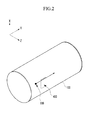
- FIG. 2 is a schematic internal perspective view showing a state in which a particulate matter sensor is disposed in an exhaust line
- FIG. 3 is a graph showing the amount of electric charges generated from a sensor unit in relation to a change of the distance from the particulate matter sensor
- FIG. 4 is a perspective view showing the front of the particulate matter sensor, in accordance with various embodiments of the present invention.
- a horizontal axis indicates the differential pressure and a vertical axis indicates collection efficiency.
- a first region 140 substantially in the center of the graph is the differential pressure region of a sensor unit in which collection efficiency of a diesel particulate filter is high, and a second region 12 is a region in which collection efficiency of a diesel particulate filter by a common or existing differential pressure sensor is 50% or less.
- a third region 10 is a region in which collection efficiency is close to zero (0) because the diesel particulate filter is damaged.
- the existing differential pressure sensor is problematic in that sensitivity in terms of collection efficiency and differential pressure is low and a sensing region is limited. Accordingly, there is a need for a new type of a differential pressure sensor or a particulate matter sensor.
- an exhaust gas flows within an exhaust line 100, and particulate matter 110 is contained in the exhaust gas.
- the particulate matter 110 passes close to the electrode portion 410 of a sensor 400 (i.e., a particulate matter sensor).
- the sensor 400 When the particulate matter 110 passes, the sensor 400 generates a signal.
- a factor that the signal is generated from the sensor 400 lies in that when charged particulate matter passes, the signal is generated by electric charges induced to the electrode portion 410 of the sensor 400.
- FIG. 3 shows an induced charge signal graph in relation to a distance x between the sensor 400 and the particulate matter.
- V x ⁇ y ⁇ z Q 4 ⁇ ⁇ ⁇ ⁇ 0 ⁇ 1 x 2 + y 2 + z - d 2 - 1 x 2 + y 2 + z + d 2
- ⁇ s ⁇ 0 ⁇ E z ⁇
- a x , a y , a z indicate respective unit vectors in the x, y, and z-axis directions in the orthogonal coordinate system.
- a signal having a pulse form is generated as shown in FIG. 3 according to a change in the distance between the charged particles and the sensing electrode.
- the senor 400 includes a body portion 430, the electrode portion 410 formed in the front of the body portion 430 on one side of the front, and power connection portions 420 formed in the front of the body portion 430 on the other side of the front.
- the electrode portion 410 formed in the front of the body portion 430 on one side of the front
- power connection portions 420 formed in the front of the body portion 430 on the other side of the front.
- FIG. 5 is a perspective view showing the rear of the particulate matter sensor in accordance with various embodiments of the present invention.
- the sensor 400 includes the body portion 430, a heating portion 500 formed in the rear of the body portion 430 on one side of the rear, and power input portion or portions 520 formed in the rear of the body portion 430 on the other side of the rear. Furthermore, the heating portion 500 and the power input portions 520 are electrically connected to each other by connection lines 510.
- the body portion 430 contains a silicon (Si) component or is made of a material comprising Si
- the heating portion 500, the connection lines 510, and the power input portions 520 contain a platinum (Pt) component or are made of a material comprising Pt.
- FIG. 6 is a detailed top plan view showing symmetrical heating portion at the rear of the particulate matter sensor in accordance with various embodiments of the present invention.
- the heating portion 500 is formed in the rear of the body portion 430 on one side of the rear, and the connection lines 510 are connected to the heating portion 500.
- the heating portion 500 has a symmetrical form on the basis of a center line 600 in the length direction of the body portion 430. More particularly, in some embodiments, the heating portion 500 include first heating lines 602 extended from the respective ends of the connection lines 510 in the width direction of the body portion 430 and configured to be adjacent to the center line 600 of the body portion 430 in the length direction of the body portion 430 at both edges of the body portion 430, second heating lines 604 extended from the respective ends of the first heating lines 602 in parallel to the center line 600 and configured to be adjacent to the center line 600, third heating lines 606 extended from the respective edges of the second heating lines 604 in the width direction of the body portion 430 and configured to be adjacent to both the edges of the body portion 430, and fourth heating lines 608 extended from the respective edges of the third heating lines 604 along both the edges of the body portion 430.
- first heating lines 602 extended from the respective ends of the connection lines 510 in the width direction of the body portion 430 and configured to be adjacent to the center line 600 of the body
- Each of the first, the second, the third, and the fourth heating lines 602, 604, 606, and 608 of the heating portion 500 has a predetermined width W1, and a predetermined gap G1 is formed between the first, the second, the third, and the fourth heating lines.
- the width and gap can be varied depending on design specifications.
- FIG. 7 is a detailed top plan view showing an asymmetrical heating portion at the rear of the particulate matter sensor in accordance with various embodiments of the present invention.
- the heating portion 500 has an asymmetrical form on the basis of the center line 600 in the length direction of the body portion 430.
- the heating portion 500 includes an edge line 700 extended along an edge of the body portion 430, first heating lines 702 extended from the end of the edge line 700 in the width direction of the body portion 430 and configured to be adjacent to an edge of the body portion 430 on the other side of the edge line 700, second heating lines 704 extended from the respective ends of the first heating lines 702 along an edge of the body portion 430, third heating lines 706 extended from the respective ends of the second heating lines 704 in the width direction of the body portion 430 and configured to be adjacent to the edge line 700, and fourth heating lines 708 extended from the respective edges of the third heating lines 706 in parallel to the edge line 700.
- Each of the first, the second, the third, the fourth, and the fifth heating lines 702, 704, 706, and 708 of the heating portion 500 has a predetermined width W1, and a predetermined gap G1 is formed between the first, the second, the third, the fourth, and the fifth heating lines.
- the width and gap can be varied depending on design specifications.
- FIG. 8 is a table showing the characteristics of the particulate matter sensor in accordance with various embodiments of the present invention.
- the body portion 430 is made of a silicon material
- the heating portion 500, the connection lines 510, and the power input portions 520 are made of a platinum material.
- a power source inputted to the power input portions 520 can be set to 20 W or about 15 W to 25 W, which can be readily varied depending on design specifications. Furthermore, temperature of an exhaust gas near the electrode portion 410 can be set to 500°C, and the temperature of the exhaust gas can vary in a range of about 150°C to 700°C.
- FIG. 9 is a table showing the experiment results of the particulate matter sensor in accordance with various embodiments of the present invention.
- max. Temp. is a maximum temperature
- min Temp. is a minimum temperature
- uniformity is the uniformity of temperature.
- Symmetric indicates that the heating portion 500 has a symmetrical line type
- asymmetric 1:1 indicates a case where a ratio of the gap and width of the line is 1:1
- asymmetric 2:1 indicates a case where a ratio of the gap and width of the line is 2:1
- asymmetric 3:1 indicates a case where a ratio of the gap and width of the line is 3:1.
- the sensor when the electrode portion 410 has a furrow type, the sensor is for removing particulate matter within the furrows of the electrode portion 410 by burning the particulate matter and can easily remove the particulate matter by burning the particulate matter at 650°C. As shown in FIG. 9 , a minimum temperature of the heating portion 500 exceeds 650°C.
Landscapes
- Chemical & Material Sciences (AREA)
- Engineering & Computer Science (AREA)
- Analytical Chemistry (AREA)
- Health & Medical Sciences (AREA)
- Life Sciences & Earth Sciences (AREA)
- Pathology (AREA)
- Biochemistry (AREA)
- General Health & Medical Sciences (AREA)
- General Physics & Mathematics (AREA)
- Immunology (AREA)
- Physics & Mathematics (AREA)
- Combustion & Propulsion (AREA)
- Dispersion Chemistry (AREA)
- Mechanical Engineering (AREA)
- General Engineering & Computer Science (AREA)
- Chemical Kinetics & Catalysis (AREA)
- Electrochemistry (AREA)
- Molecular Biology (AREA)
- Processes For Solid Components From Exhaust (AREA)
- Investigating Or Analyzing Materials By The Use Of Electric Means (AREA)
- Exhaust Gas After Treatment (AREA)
Abstract
Description
- The present application claims priority of Korean Patent Application Number
10-2012-0147764 filed December 17, 2012 - The present invention relates to a particulate matter sensor unit for precisely and effectively sensing damage to a particulate filter configured to filter particulate matter (or an exhaust gas) contained in an exhaust gas and maintaining sensitivity.
- A particulate filter (PF) for reducing an exhaust gas is applied to a vehicle. A differential pressure sensor is used to sense the amount of an exhaust gas collected by the particulate filter.
- The particulate filter can be selectively applied to all internal combustion engines, such as a diesel vehicle, a gasoline vehicle, and a gas vehicle.
- In use, in accordance with exhaust gas control, the sensing precision of particulate matter collected by a diesel particulate filter by using the existing differential pressure sensor can be lowered, and it is not easy to sense damage to the diesel particulate filter.
- Meanwhile, research into a sensor for sensing particulate matter continues to be carried out, and research is also being carried out in order to maintain the sensitivity of a sensor by removing particulate matter when the particulate matter is adhered to the sensor.
- The information disclosed in this Background section is only for enhancement of understanding of the general background of the invention and should not be taken as an acknowledgement or any form of suggestion that this information forms the prior art already known to a person skilled in the art.
- The present invention has been made in an effort to provide a particular matter sensor unit having advantages of precisely sensing the amount of an exhaust gas slipped into the rear part of a particulate filter, precisely sensing the amount of an exhaust gas collected by the particulate filter and whether the particulate filter has been damaged or not based on the amount of the sensed exhaust gas, and easily removing particulate matter adhered to an electrode portion.
- A particulate matter sensor unit in accordance with various aspects of the present invention may include a sensor disposed on one side of an exhaust line and configured to employ an electrostatic induction for generating electric charges by a particulate matter contained in an exhaust gas when the particulate matter passes the sensor or flows adjacent to the sensor. The sensor may include a body portion, an electrode portion formed in a front of the body portion on one side of the front and configured to be adjacent to the particulate matter, a heating portion formed in a rear of the body portion on a respective side of the rear corresponding to the electrode portion, a power input portion formed in the rear of the body portion on the other side of the rear and configured to supply a power to the heating portion, and connection lines configured to connect the power input portion to the heating portion, wherein the heating portion uses the supplied power to generate heat for removing the particulate matter adhered to the electrode portion by burning the particulate matter.
- The electrode portion may have a furrow or a plurality of furrows extending substantially in a cross direction with respect to a flow direction of the exhaust gas, and the electrode portion may be formed substantially vertically with respect to the flow direction of the exhaust gas.
- The heating portion, the connection lines, and the power input portions may be made of a material comprising platinum (Pt). The body portion may be made of a material comprising silicon (Si). The power inputted to the power input portions may be about 15 W to 25 W, and an external temperature of the body portion may be about 150 °C to 700 °C. The connection lines configured to connect the heating portion to the power input portion may be formed along the edges of the body portion.
- The heating portion may include first heating lines extended from the respective ends of the connection lines in the width direction of the body portion and configured to be adjacent to the center line of the body portion in the length direction of the body portion at both edges of the body portion, second heating lines extended from the respective ends of the first heating lines substantially parallel to the center line and configured to be adjacent to the center line, third heating lines extended from the respective edges of the second heating lines in the width direction of the body portion and configured to be adjacent to both the edges of the body portion, and fourth heating lines extended from the respective edges of the third heating lines along both the edges of the body portion.
- The heating portion may have a symmetric shape with respect to the center line in the length direction of the body portion.
- The heating portion may include an edge line extended along an edge of the body portion, first heating lines extended from the end of the edge line in a width direction of the body portion and configured to be adjacent to the edge of the body portion on another side of the edge line with respect to the edge of the body portion, second heating lines extended from the respective ends of the first heating lines along the edge of the body portion, third heating lines extended from the respective ends of the second heating lines in the width direction of the body portion and configured to be adjacent to the edge line, and fourth heating lines extended from the respective edges of the third heating lines substantially parallel to the edge line.
- Each of the first, the second, the third, and the fourth heating lines may have a predetermined width, and a predetermined gap may be formed between the first, the second, the third, and the fourth heating lines.
- The particulate matter sensor unit in accordance with various aspects of the present invention can precisely sense the amount of collected particulate matter, such as an exhaust gas of a Diesel Particulate Filter (DPF), or the amount of particulate matter contained in an exhaust gas and easily removing particulate matter adhered to an electrode portion by heating the adhered particulate matter using a heating portion.
- The methods and apparatuses of the present invention have other features and advantages which will be apparent from or are set forth in more detail in the accompanying drawings, which are incorporated herein, and the following Detailed Description, which together serve to explain certain principles of the present invention.
-
-
FIG. 1 is a graph showing the amount of particulate matter collected by a diesel particulate filter in relation to differential pressure. -
FIG. 2 is a schematic internal perspective view showing a state in which an exemplary particulate matter sensor in accordance with the present invention is disposed in an exhaust line. -
FIG. 3 is a graph showing the amount of electric charges generated from an exemplary sensor unit in relation to a distance between a particulate matter sensor and the particulate matter in accordance with the present invention. -
FIG. 4 is a perspective view showing the front of an exemplary particulate matter sensor in accordance with the present invention. -
FIG. 5 is a perspective view showing the rear of an exemplary particulate matter sensor in accordance with the present invention. -
FIG. 6 is a detailed top plan view showing a symmetrical heating portion at the rear of an exemplary particulate matter sensor in accordance with the present invention. -
FIG. 7 is a detailed top plan view showing an asymmetrical heating portion at the rear of an exemplary particulate matter sensor in accordance with the present invention. -
FIG. 8 is a table showing the characteristics of an exemplary particulate matter sensor in accordance with the present invention. -
FIG. 9 is a table showing the experiment results of an exemplary particulate matter sensor in accordance with the present invention. - Reference will now be made in detail to various embodiments of the present invention(s), examples of which are illustrated in the accompanying drawings and described below. While the invention(s) will be described in conjunction with exemplary embodiments, it will be understood that present description is not intended to limit the invention(s) to those exemplary embodiments. On the contrary, the invention(s) is/are intended to cover not only the exemplary embodiments, but also various alternatives, modifications, equivalents and other embodiments, which may be included within the spirit and scope of the invention as defined by the appended claims.
- In various embodiments of the present invention, an example in which a sensor 120 is applied to a diesel particulate filter is illustrated, but the present invention is not limited thereto. The sensor can be selectively applied to all internal combustion engines that discharge particulate matter, such as a gasoline engine, a gas engine, and a bio engine using bio fuel. Accordingly, the sensor in accordance with various embodiments of the present invention can be changed into and applied to a particulate filter, a diesel particulate filter, and a gasoline particulate filter.
-
FIG. 1 is a graph showing the amount of particulate matter collected by a diesel particulate filter,FIG. 2 is a schematic internal perspective view showing a state in which a particulate matter sensor is disposed in an exhaust line,FIG. 3 is a graph showing the amount of electric charges generated from a sensor unit in relation to a change of the distance from the particulate matter sensor, andFIG. 4 is a perspective view showing the front of the particulate matter sensor, in accordance with various embodiments of the present invention. - Referring to
FIG. 1 , a horizontal axis indicates the differential pressure and a vertical axis indicates collection efficiency. Afirst region 140 substantially in the center of the graph is the differential pressure region of a sensor unit in which collection efficiency of a diesel particulate filter is high, and asecond region 12 is a region in which collection efficiency of a diesel particulate filter by a common or existing differential pressure sensor is 50% or less. Furthermore, athird region 10 is a region in which collection efficiency is close to zero (0) because the diesel particulate filter is damaged. - As shown in
FIG. 1 , the existing differential pressure sensor is problematic in that sensitivity in terms of collection efficiency and differential pressure is low and a sensing region is limited. Accordingly, there is a need for a new type of a differential pressure sensor or a particulate matter sensor. - Referring to
FIGS. 2 and4 , an exhaust gas flows within anexhaust line 100, andparticulate matter 110 is contained in the exhaust gas. Theparticulate matter 110 passes close to theelectrode portion 410 of a sensor 400 (i.e., a particulate matter sensor). When theparticulate matter 110 passes, thesensor 400 generates a signal. A factor that the signal is generated from thesensor 400 lies in that when charged particulate matter passes, the signal is generated by electric charges induced to theelectrode portion 410 of thesensor 400. -
FIG. 3 shows an induced charge signal graph in relation to a distance x between thesensor 400 and the particulate matter. In general, an electric field generated by charged particles is represented by the following equation:
where Q is the amount of electric charges of the charged particles, and r is a distance from the charged particles. Furthermore, εo is a dielectric constant in vacuum. - Surface charges having the same value as a value of an electric field generated by charged particulate matter at the interface of a sensor electrode are generated in the sensor electrode. The induced charges can be solved by Laplace's equation. Assuming that charged dot charges having the amount of electric charges of a Q value in related to a flat conductor plate that is placed on a plane in which z is zero (0) in an orthogonal coordinate system are placed at (0,0,d), potential generated by the dot charges and the density of surface charges induced by the dot charges can be represented by the following equations.
- For the potential generated by the dot charges:

- For the electric field generated by the dot charges:

- For the density of induced surface charges:

whereax ,ay ,az indicate respective unit vectors in the x, y, and z-axis directions in the orthogonal coordinate system. - If the amount of electric charges induced into the sensing electrode by the charged particles in relation to the distance x is represented by a graph, a signal having a pulse form is generated as shown in
FIG. 3 according to a change in the distance between the charged particles and the sensing electrode. - Referring to
FIG. 4 , thesensor 400 includes abody portion 430, theelectrode portion 410 formed in the front of thebody portion 430 on one side of the front, andpower connection portions 420 formed in the front of thebody portion 430 on the other side of the front. When particulate matter contained in an exhaust gas passes close to theelectrode portion 410, electric charges are generated and then transferred to an external control unit through thepower connection portions 420. -
FIG. 5 is a perspective view showing the rear of the particulate matter sensor in accordance with various embodiments of the present invention. Referring toFIG. 5 , thesensor 400 includes thebody portion 430, aheating portion 500 formed in the rear of thebody portion 430 on one side of the rear, and power input portion orportions 520 formed in the rear of thebody portion 430 on the other side of the rear. Furthermore, theheating portion 500 and thepower input portions 520 are electrically connected to each other byconnection lines 510. - In various embodiments of the present invention, the
body portion 430 contains a silicon (Si) component or is made of a material comprising Si, and theheating portion 500, theconnection lines 510, and thepower input portions 520 contain a platinum (Pt) component or are made of a material comprising Pt. -
FIG. 6 is a detailed top plan view showing symmetrical heating portion at the rear of the particulate matter sensor in accordance with various embodiments of the present invention. Referring toFIG. 6 , theheating portion 500 is formed in the rear of thebody portion 430 on one side of the rear, and theconnection lines 510 are connected to theheating portion 500. - In some embodiments, the
heating portion 500 has a symmetrical form on the basis of acenter line 600 in the length direction of thebody portion 430. More particularly, in some embodiments, theheating portion 500 includefirst heating lines 602 extended from the respective ends of theconnection lines 510 in the width direction of thebody portion 430 and configured to be adjacent to thecenter line 600 of thebody portion 430 in the length direction of thebody portion 430 at both edges of thebody portion 430,second heating lines 604 extended from the respective ends of thefirst heating lines 602 in parallel to thecenter line 600 and configured to be adjacent to thecenter line 600,third heating lines 606 extended from the respective edges of thesecond heating lines 604 in the width direction of thebody portion 430 and configured to be adjacent to both the edges of thebody portion 430, andfourth heating lines 608 extended from the respective edges of thethird heating lines 604 along both the edges of thebody portion 430. - Each of the first, the second, the third, and the
fourth heating lines heating portion 500 has a predetermined width W1, and a predetermined gap G1 is formed between the first, the second, the third, and the fourth heating lines. The width and gap can be varied depending on design specifications. -
FIG. 7 is a detailed top plan view showing an asymmetrical heating portion at the rear of the particulate matter sensor in accordance with various embodiments of the present invention. In some embodiments, theheating portion 500 has an asymmetrical form on the basis of thecenter line 600 in the length direction of thebody portion 430. - More particularly, in some embodiments, the
heating portion 500 includes anedge line 700 extended along an edge of thebody portion 430,first heating lines 702 extended from the end of theedge line 700 in the width direction of thebody portion 430 and configured to be adjacent to an edge of thebody portion 430 on the other side of theedge line 700, second heating lines 704 extended from the respective ends of thefirst heating lines 702 along an edge of thebody portion 430,third heating lines 706 extended from the respective ends of the second heating lines 704 in the width direction of thebody portion 430 and configured to be adjacent to theedge line 700, andfourth heating lines 708 extended from the respective edges of thethird heating lines 706 in parallel to theedge line 700. - Each of the first, the second, the third, the fourth, and the
fifth heating lines heating portion 500 has a predetermined width W1, and a predetermined gap G1 is formed between the first, the second, the third, the fourth, and the fifth heating lines. The width and gap can be varied depending on design specifications. -
FIG. 8 is a table showing the characteristics of the particulate matter sensor in accordance with various embodiments of the present invention. Referring toFIG. 8 , thebody portion 430 is made of a silicon material, and theheating portion 500, theconnection lines 510, and thepower input portions 520 are made of a platinum material. - A power source inputted to the
power input portions 520 can be set to 20 W or about 15 W to 25 W, which can be readily varied depending on design specifications. Furthermore, temperature of an exhaust gas near theelectrode portion 410 can be set to 500°C, and the temperature of the exhaust gas can vary in a range of about 150°C to 700°C. -
FIG. 9 is a table showing the experiment results of the particulate matter sensor in accordance with various embodiments of the present invention. InFIG. 9 , max. Temp. is a maximum temperature, min Temp. is a minimum temperature, and uniformity is the uniformity of temperature. Symmetric indicates that theheating portion 500 has a symmetrical line type, asymmetric 1:1 indicates a case where a ratio of the gap and width of the line is 1:1, asymmetric 2:1 indicates a case where a ratio of the gap and width of the line is 2:1, and asymmetric 3:1 indicates a case where a ratio of the gap and width of the line is 3:1. - In various embodiments of the present invention, when the
electrode portion 410 has a furrow type, the sensor is for removing particulate matter within the furrows of theelectrode portion 410 by burning the particulate matter and can easily remove the particulate matter by burning the particulate matter at 650°C. As shown inFIG. 9 , a minimum temperature of theheating portion 500 exceeds 650°C. - For convenience in explanation and accurate definition in the appended claims, the terms "front" or "rear", and etc. are used to describe features of the exemplary embodiments with reference to the positions of such features as displayed in the figures.
- The foregoing descriptions of specific exemplary embodiments of the present invention have been presented for purposes of illustration and description. They are not intended to be exhaustive or to limit the invention to the precise forms disclosed, and obviously many modifications and variations are possible in light of the above teachings. The exemplary embodiments were chosen and described in order to explain certain principles of the invention and their practical application, to thereby enable others skilled in the art to make and utilize various exemplary embodiments of the present invention, as well as various alternatives and modifications thereof. It is intended that the scope of the invention be defined by the Claims appended hereto and their equivalents.
Claims (11)
- A particulate matter sensor unit, comprising:a sensor (400) disposed on one side of an exhaust line (100) and configured to employ an electrostatic induction for generating electric charges by a particulate matter (110) contained in an exhaust gas when the particulate matter passes the sensor or flows adjacent to the sensor, wherein the sensor comprises:a body portion (430);an electrode portion (410) formed in a front of the body portion on one side of the front and configured to be adjacent to the particulate matter;a heating portion (500) formed in a rear of the body portion on a respective side of the rear corresponding to the electrode portion;a power input portion (520) formed in the rear of the body portion on the other side of the rear and configured to supply a power to the heating portion; andconnection lines (510) configured to connect the power input portion to the heating portion,wherein the heating portion uses the supplied power to generate heat for removing the particulate matter adhered to the electrode portion by burning the particulate matter.
- The particulate matter sensor unit of claim 1, wherein the electrode portion (410) has a furrow or a plurality of furrows extending substantially in a cross direction with respect to a flow direction of the exhaust gas, and the electrode portion is formed substantially vertically with respect to the flow direction of the exhaust gas.
- The particulate matter sensor unit of claim 1 or 2, wherein the heating portion (500), the connection lines (510), and/or the power input portion (520) are made of a material comprising platinum (Pt).
- The particulate matter sensor unit of any of claims 1-3, wherein the body portion (430) is made of a material comprising silicon (Si).
- The particulate matter sensor unit of any of claims 1-4, wherein the power inputted to the power input portion (520) is about 15 W to 25 W, and an external temperature of the body portion (430) is about 150 °C to 700 °C.
- The particulate matter sensor unit of any of claims 1-5, wherein the connection lines (510) configured to connect the heating portion (500) to the power input portion (520) are formed along edges of the body portion (430).
- The particulate matter sensor unit of any of claims 1-6, wherein the heating portion (500) comprises:first heating lines (602) extended from respective ends of the connection lines in a width direction of the body portion and configured to be adjacent to a center line of the body portion in a length direction of the body portion at both edges of the body portion;second heating lines (604) extended from respective ends of the first heating lines substantially parallel to the center line and configured to be adjacent to the center line;third heating lines (606) extended from respective edges of the second heating lines in the width direction of the body portion and configured to be adj acent to both the edges of the body portion; andfourth heating lines (608) extended from respective edges of the third heating lines along both the edges of the body portion.
- The particulate matter sensor unit of claim 7, wherein the heating portion (500) has a symmetric shape with respect to the center line in the length direction of the body portion.
- The particulate matter sensor unit of any of claims 1-6, wherein the heating portion (500) comprises:an edge line (700) extended along an edge of the body portion;first heating lines (702) extended from an end of the edge line in a width direction of the body portion and configured to be adjacent to the edge of the body portion on another side of the edge line with respect to the edge of the body portion;second heating lines (704) extended from respective ends of the first heating lines along the edge of the body portion;third heating lines (706) extended from respective ends of the second heating lines in the width direction of the body portion and configured to be adjacent to the edge line; andfourth heating lines (708) extended from respective edges of the third heating lines substantially parallel to the edge line.
- The particulate matter sensor unit of claim 7 or 8, wherein each of the first, the second, the third, and the fourth heating lines has a predetermined width, and a predetermined gap is formed between the first, the second, the third, and the fourth heating lines.
- The particulate matter sensor unit of claim 9, wherein each of the first, the second, the third, and the fourth heating lines has a predetermined width, and a predetermined gap is formed between the first, the second, the third, and the fourth heating lines.
Applications Claiming Priority (1)
| Application Number | Priority Date | Filing Date | Title |
|---|---|---|---|
| KR20120147764 | 2012-12-17 |
Publications (2)
| Publication Number | Publication Date |
|---|---|
| EP2743672A2 true EP2743672A2 (en) | 2014-06-18 |
| EP2743672A3 EP2743672A3 (en) | 2017-12-06 |
Family
ID=49911195
Family Applications (1)
| Application Number | Title | Priority Date | Filing Date |
|---|---|---|---|
| EP13197603.7A Ceased EP2743672A3 (en) | 2012-12-17 | 2013-12-17 | Particulate matter sensor unit |
Country Status (4)
| Country | Link |
|---|---|
| US (1) | US9354196B2 (en) |
| EP (1) | EP2743672A3 (en) |
| JP (1) | JP2014118968A (en) |
| CN (1) | CN103868826A (en) |
Families Citing this family (4)
| Publication number | Priority date | Publication date | Assignee | Title |
|---|---|---|---|---|
| RU2707983C2 (en) * | 2015-02-17 | 2019-12-03 | Форд Глобал Текнолоджиз, Ллк | System (embodiments) and method of measuring parameters of solid particles |
| US10078043B2 (en) * | 2016-03-08 | 2018-09-18 | Ford Global Technologies, Llc | Method and system for exhaust particulate matter sensing |
| US10018098B2 (en) * | 2016-04-14 | 2018-07-10 | Ford Global Technologies, Llc | Method and system for exhaust particulate matter sensing |
| DE112018004042T5 (en) * | 2017-09-06 | 2020-08-06 | Ngk Insulators, Ltd. | PARTICLE DETECTING ELEMENT AND PARTICLE DETECTOR |
Citations (4)
| Publication number | Priority date | Publication date | Assignee | Title |
|---|---|---|---|---|
| WO2006077197A1 (en) * | 2005-01-21 | 2006-07-27 | Robert Bosch Gmbh | Sensor element for particle sensors and method for operating the same |
| JP2008151524A (en) * | 2006-12-14 | 2008-07-03 | Matsushita Electric Ind Co Ltd | Condensation sensor |
| US20080265870A1 (en) * | 2007-04-27 | 2008-10-30 | Nair Balakrishnan G | Particulate Matter Sensor |
| EP2725339A2 (en) * | 2012-10-25 | 2014-04-30 | Hyundai Motor Company | Particulate matter sensor unit |
Family Cites Families (27)
| Publication number | Priority date | Publication date | Assignee | Title |
|---|---|---|---|---|
| US4656832A (en) * | 1982-09-30 | 1987-04-14 | Nippondenso Co., Ltd. | Detector for particulate density and filter with detector for particulate density |
| US4456883A (en) * | 1982-10-04 | 1984-06-26 | Ambac Industries, Incorporated | Method and apparatus for indicating an operating characteristic of an internal combustion engine |
| JPS6039542A (en) * | 1983-08-12 | 1985-03-01 | Ngk Spark Plug Co Ltd | Smoke density detecting method |
| US4512200A (en) * | 1983-11-30 | 1985-04-23 | The Babcock & Wilcox Company | Pulverized coal relative distribution meter |
| JPH0639938B2 (en) * | 1986-11-21 | 1994-05-25 | 日本特殊陶業株式会社 | Smoke detection device for diesel engine |
| US4939466A (en) * | 1989-04-10 | 1990-07-03 | Board Of Control Of Michigan Technological University | Method and apparatus for sensing the regeneration of a diesel engine particulate trap |
| CN1162118A (en) * | 1996-04-09 | 1997-10-15 | Lg电子株式会社 | Method and device for measuring meat with gas sensor and method for making gas sensor |
| DE10124907A1 (en) * | 2001-05-22 | 2002-11-28 | Bosch Gmbh Robert | Electrode assembly for monitoring soot in the exhaust channel of an IC engine, or a oil heating system, has an insulation holder body with a working electrode, and a test electrode to monitor the body insulation resistance |
| JP2003057200A (en) * | 2001-08-20 | 2003-02-26 | Kansai Ootomeishiyon Kk | Powder concentration measurement device |
| JP2003098136A (en) * | 2001-09-27 | 2003-04-03 | Horiba Ltd | Granular substance sensor and method for measuring granular substance using the same |
| JP2005010083A (en) | 2003-06-20 | 2005-01-13 | Sharp Corp | Particle detection sensor and particle detection measurement apparatus using the same. |
| DE102004043121A1 (en) * | 2004-09-07 | 2006-03-09 | Robert Bosch Gmbh | Sensor element for particle sensors and method for operating the same |
| DE102005030134A1 (en) * | 2005-06-28 | 2007-01-04 | Siemens Ag | Sensor and operating method for the detection of soot |
| US7765792B2 (en) * | 2005-10-21 | 2010-08-03 | Honeywell International Inc. | System for particulate matter sensor signal processing |
| DE102005053120A1 (en) * | 2005-11-08 | 2007-05-10 | Robert Bosch Gmbh | Sensor element for gas sensors and method for operating the same |
| JP4898902B2 (en) * | 2007-03-27 | 2012-03-21 | 日本碍子株式会社 | Particle sensor |
| US20090056416A1 (en) * | 2007-08-30 | 2009-03-05 | Nair Balakrishnan G | Ceramic Particulate Matter Sensor With Low Electrical Leakage |
| JP4758488B2 (en) * | 2009-02-16 | 2011-08-31 | 本田技研工業株式会社 | Particulate matter detector |
| JP2010210534A (en) * | 2009-03-12 | 2010-09-24 | Ngk Insulators Ltd | Particulate matter detector |
| JP2011080781A (en) | 2009-10-05 | 2011-04-21 | Nippon Soken Inc | Particulate sensing element and particulate sensor using the same |
| JP2011080942A (en) | 2009-10-09 | 2011-04-21 | Nippon Soken Inc | Particulate detection sensor |
| JP5463935B2 (en) | 2010-01-27 | 2014-04-09 | いすゞ自動車株式会社 | PM sensor and exhaust system |
| WO2011106625A1 (en) * | 2010-02-25 | 2011-09-01 | Stoneridge, Inc. | Soot sensor system |
| JP2012012960A (en) * | 2010-06-29 | 2012-01-19 | Nippon Soken Inc | Particulate matter detection sensor |
| JP2012083210A (en) | 2010-10-12 | 2012-04-26 | Denso Corp | Particulate substance detection sensor |
| JP5418611B2 (en) * | 2011-04-21 | 2014-02-19 | 株式会社デンソー | Method for correcting particulate matter detection device |
| KR101305198B1 (en) * | 2011-12-09 | 2013-09-26 | 현대자동차주식회사 | Particulate matters sensor unit |
-
2013
- 2013-06-20 JP JP2013129676A patent/JP2014118968A/en active Pending
- 2013-12-06 US US14/099,144 patent/US9354196B2/en not_active Expired - Fee Related
- 2013-12-16 CN CN201310690506.5A patent/CN103868826A/en active Pending
- 2013-12-17 EP EP13197603.7A patent/EP2743672A3/en not_active Ceased
Patent Citations (4)
| Publication number | Priority date | Publication date | Assignee | Title |
|---|---|---|---|---|
| WO2006077197A1 (en) * | 2005-01-21 | 2006-07-27 | Robert Bosch Gmbh | Sensor element for particle sensors and method for operating the same |
| JP2008151524A (en) * | 2006-12-14 | 2008-07-03 | Matsushita Electric Ind Co Ltd | Condensation sensor |
| US20080265870A1 (en) * | 2007-04-27 | 2008-10-30 | Nair Balakrishnan G | Particulate Matter Sensor |
| EP2725339A2 (en) * | 2012-10-25 | 2014-04-30 | Hyundai Motor Company | Particulate matter sensor unit |
Also Published As
| Publication number | Publication date |
|---|---|
| US9354196B2 (en) | 2016-05-31 |
| CN103868826A (en) | 2014-06-18 |
| EP2743672A3 (en) | 2017-12-06 |
| JP2014118968A (en) | 2014-06-30 |
| US20140165699A1 (en) | 2014-06-19 |
Similar Documents
| Publication | Publication Date | Title |
|---|---|---|
| US9354196B2 (en) | Particulate matter sensor unit | |
| US20150316448A1 (en) | Particulate matter sensor unit | |
| DE102012105533B4 (en) | particle sensor unit | |
| US8539817B2 (en) | Particulate matter detection device | |
| CN107883863A (en) | Live body is close to distance detection device | |
| EP3368882B1 (en) | Method and apparatus for measuring aerosol particles of exhaust gas | |
| CN101896808B (en) | Device for characterizing a size distribution of electrically-charged airborne particles in an air flow | |
| US20140223887A1 (en) | Method and device for measuring the concentration of soot particles in an exhaust gas, in particular from an internal combustion engine | |
| US7707875B2 (en) | Soot collection quantity measuring device for diesel particulate filter | |
| DE112015004134T5 (en) | Temperature sensor device | |
| EP3159685A1 (en) | Sensor | |
| US20190323941A1 (en) | Method and system for exhaust particulate matter sensing | |
| EP3056700A1 (en) | Exhaust purification system | |
| US20200200667A1 (en) | Particle detection element and particle detector | |
| KR101558373B1 (en) | Sensor unit that senses particulate matters | |
| CN106795793B (en) | sensor | |
| US9422853B2 (en) | Trapped soot measurement | |
| DE112016002988T9 (en) | Particle sensor and particle scanning system | |
| CN107709967A (en) | Particle-like substance sensor and the waste gas cleaning system for including it | |
| CN104512257A (en) | Vehicle operational cost display system and method | |
| Sherwood | Electrostatic Induction Electrode Systems for Beam-Position Detection | |
| JP2019045504A (en) | Fine particle detection element and fine particle detector | |
| CN108303355A (en) | Device and method for detecting particulate matter | |
| CN110132807A (en) | Particulate detector | |
| Ramechecandane et al. | Modelling Particulate Removal in Tubular Wet Electrostatic Precipitators Using a Modified Drift Flux Model. |
Legal Events
| Date | Code | Title | Description |
|---|---|---|---|
| PUAI | Public reference made under article 153(3) epc to a published international application that has entered the european phase |
Free format text: ORIGINAL CODE: 0009012 |
|
| 17P | Request for examination filed |
Effective date: 20131217 |
|
| AK | Designated contracting states |
Kind code of ref document: A2 Designated state(s): AL AT BE BG CH CY CZ DE DK EE ES FI FR GB GR HR HU IE IS IT LI LT LU LV MC MK MT NL NO PL PT RO RS SE SI SK SM TR |
|
| AX | Request for extension of the european patent |
Extension state: BA ME |
|
| PUAL | Search report despatched |
Free format text: ORIGINAL CODE: 0009013 |
|
| AK | Designated contracting states |
Kind code of ref document: A3 Designated state(s): AL AT BE BG CH CY CZ DE DK EE ES FI FR GB GR HR HU IE IS IT LI LT LU LV MC MK MT NL NO PL PT RO RS SE SI SK SM TR |
|
| AX | Request for extension of the european patent |
Extension state: BA ME |
|
| RIC1 | Information provided on ipc code assigned before grant |
Ipc: G01N 15/06 20060101AFI20171030BHEP Ipc: F01N 13/00 20100101ALI20171030BHEP |
|
| STAA | Information on the status of an ep patent application or granted ep patent |
Free format text: STATUS: REQUEST FOR EXAMINATION WAS MADE |
|
| R17P | Request for examination filed (corrected) |
Effective date: 20180605 |
|
| RBV | Designated contracting states (corrected) |
Designated state(s): AL AT BE BG CH CY CZ DE DK EE ES FI FR GB GR HR HU IE IS IT LI LT LU LV MC MK MT NL NO PL PT RO RS SE SI SK SM TR |
|
| STAA | Information on the status of an ep patent application or granted ep patent |
Free format text: STATUS: EXAMINATION IS IN PROGRESS |
|
| 17Q | First examination report despatched |
Effective date: 20200205 |
|
| STAA | Information on the status of an ep patent application or granted ep patent |
Free format text: STATUS: THE APPLICATION HAS BEEN REFUSED |
|
| 18R | Application refused |
Effective date: 20201008 |