EP2743586A2 - Systems and methods for late lean injection premixing - Google Patents
Systems and methods for late lean injection premixing Download PDFInfo
- Publication number
- EP2743586A2 EP2743586A2 EP13196758.0A EP13196758A EP2743586A2 EP 2743586 A2 EP2743586 A2 EP 2743586A2 EP 13196758 A EP13196758 A EP 13196758A EP 2743586 A2 EP2743586 A2 EP 2743586A2
- Authority
- EP
- European Patent Office
- Prior art keywords
- fuel
- interior
- elongate
- premixing
- compressor discharge
- Prior art date
- Legal status (The legal status is an assumption and is not a legal conclusion. Google has not performed a legal analysis and makes no representation as to the accuracy of the status listed.)
- Withdrawn
Links
- 238000002347 injection Methods 0.000 title claims abstract description 18
- 239000007924 injection Substances 0.000 title claims abstract description 18
- 238000000034 method Methods 0.000 title claims description 17
- 239000000446 fuel Substances 0.000 claims abstract description 116
- 239000012530 fluid Substances 0.000 claims abstract description 19
- 238000004891 communication Methods 0.000 claims abstract description 15
- 238000002485 combustion reaction Methods 0.000 claims description 12
- 230000008878 coupling Effects 0.000 claims 1
- 238000010168 coupling process Methods 0.000 claims 1
- 238000005859 coupling reaction Methods 0.000 claims 1
- 239000007789 gas Substances 0.000 description 20
- 230000007704 transition Effects 0.000 description 7
- 239000000567 combustion gas Substances 0.000 description 5
- 239000000203 mixture Substances 0.000 description 5
- UGFAIRIUMAVXCW-UHFFFAOYSA-N Carbon monoxide Chemical compound [O+]#[C-] UGFAIRIUMAVXCW-UHFFFAOYSA-N 0.000 description 3
- 230000004323 axial length Effects 0.000 description 3
- 229910002091 carbon monoxide Inorganic materials 0.000 description 3
- 238000010586 diagram Methods 0.000 description 3
- 238000001816 cooling Methods 0.000 description 2
- 239000003344 environmental pollutant Substances 0.000 description 2
- 239000000463 material Substances 0.000 description 2
- VNWKTOKETHGBQD-UHFFFAOYSA-N methane Chemical compound C VNWKTOKETHGBQD-UHFFFAOYSA-N 0.000 description 2
- 231100000719 pollutant Toxicity 0.000 description 2
- 238000010248 power generation Methods 0.000 description 2
- GQPLMRYTRLFLPF-UHFFFAOYSA-N Nitrous Oxide Chemical class [O-][N+]#N GQPLMRYTRLFLPF-UHFFFAOYSA-N 0.000 description 1
- 230000000712 assembly Effects 0.000 description 1
- 238000000429 assembly Methods 0.000 description 1
- 230000018109 developmental process Effects 0.000 description 1
- 230000005611 electricity Effects 0.000 description 1
- 239000003345 natural gas Substances 0.000 description 1
- 238000011144 upstream manufacturing Methods 0.000 description 1
Images

Classifications
-
- F—MECHANICAL ENGINEERING; LIGHTING; HEATING; WEAPONS; BLASTING
- F23—COMBUSTION APPARATUS; COMBUSTION PROCESSES
- F23R—GENERATING COMBUSTION PRODUCTS OF HIGH PRESSURE OR HIGH VELOCITY, e.g. GAS-TURBINE COMBUSTION CHAMBERS
- F23R3/00—Continuous combustion chambers using liquid or gaseous fuel
- F23R3/28—Continuous combustion chambers using liquid or gaseous fuel characterised by the fuel supply
- F23R3/36—Supply of different fuels
-
- F—MECHANICAL ENGINEERING; LIGHTING; HEATING; WEAPONS; BLASTING
- F23—COMBUSTION APPARATUS; COMBUSTION PROCESSES
- F23R—GENERATING COMBUSTION PRODUCTS OF HIGH PRESSURE OR HIGH VELOCITY, e.g. GAS-TURBINE COMBUSTION CHAMBERS
- F23R3/00—Continuous combustion chambers using liquid or gaseous fuel
- F23R3/02—Continuous combustion chambers using liquid or gaseous fuel characterised by the air-flow or gas-flow configuration
- F23R3/04—Air inlet arrangements
- F23R3/06—Arrangement of apertures along the flame tube
-
- F—MECHANICAL ENGINEERING; LIGHTING; HEATING; WEAPONS; BLASTING
- F23—COMBUSTION APPARATUS; COMBUSTION PROCESSES
- F23R—GENERATING COMBUSTION PRODUCTS OF HIGH PRESSURE OR HIGH VELOCITY, e.g. GAS-TURBINE COMBUSTION CHAMBERS
- F23R3/00—Continuous combustion chambers using liquid or gaseous fuel
- F23R3/28—Continuous combustion chambers using liquid or gaseous fuel characterised by the fuel supply
- F23R3/286—Continuous combustion chambers using liquid or gaseous fuel characterised by the fuel supply having fuel-air premixing devices
-
- F—MECHANICAL ENGINEERING; LIGHTING; HEATING; WEAPONS; BLASTING
- F23—COMBUSTION APPARATUS; COMBUSTION PROCESSES
- F23R—GENERATING COMBUSTION PRODUCTS OF HIGH PRESSURE OR HIGH VELOCITY, e.g. GAS-TURBINE COMBUSTION CHAMBERS
- F23R3/00—Continuous combustion chambers using liquid or gaseous fuel
- F23R3/28—Continuous combustion chambers using liquid or gaseous fuel characterised by the fuel supply
- F23R3/34—Feeding into different combustion zones
-
- F—MECHANICAL ENGINEERING; LIGHTING; HEATING; WEAPONS; BLASTING
- F23—COMBUSTION APPARATUS; COMBUSTION PROCESSES
- F23R—GENERATING COMBUSTION PRODUCTS OF HIGH PRESSURE OR HIGH VELOCITY, e.g. GAS-TURBINE COMBUSTION CHAMBERS
- F23R3/00—Continuous combustion chambers using liquid or gaseous fuel
- F23R3/28—Continuous combustion chambers using liquid or gaseous fuel characterised by the fuel supply
- F23R3/34—Feeding into different combustion zones
- F23R3/346—Feeding into different combustion zones for staged combustion
Definitions
- Embodiments of the present application relate generally to gas turbine engines and more particularly to combustor assemblies including late lean injection (LLI) premixing.
- LLI late lean injection
- LLI involves the injection of combustible materials into the flow of the high energy fluids at a location downstream from the normal combustion zone in the combustor. This downstream location could be defined as a section of the combustor liner or at a section of the transition piece. In any case, the combustible materials injected at this location increase the temperature and energy of the high energy fluids and lead to an increased consumption of CO with little to no significant increase in NOx for reasonable levels of LLI fuel flow.
- the LLI combustor assembly may include a first interior in which a first fuel supplied thereto is combustible.
- the LLI combustor assembly may also include a flow sleeve annulus including a second interior in which a second fuel supplied thereto is combustible.
- the flow sleeve annulus may fluidly couple the first interior and the second interior.
- the LLI combustor assembly may also include at least one fuel injector disposed about the second interior. The at least one fuel injector may be configured to supply the second fuel to the second interior.
- the LLI combustor assembly may also include at least one elongate premixing conduit disposed about the flow sleeve annulus and in fluid communication with the at least one fuel injector.
- the at least one elongate premixing conduit may be in fluid communication with a compressor discharge air and the second fuel such that the compressor discharge air and the second fuel are premixed within the elongate premixing conduit before entering the second interior by way of the at least one fuel injector.
- the gas turbine engine assembly may include a combustor having a first interior in which a first fuel supplied thereto is combustible.
- the gas turbine engine assembly may also include a turbine that receives the products of at least the combustion of the first fuel.
- the gas turbine engine assembly may also include a flow sleeve annulus including a second interior in which a second fuel supplied thereto and the products of the combustion of the first fuel are combustible.
- the flow sleeve annulus may fluidly couple the combustor and the turbine.
- the gas turbine engine assembly may also include at least one fuel injector disposed about the second interior and configured to supply the second fuel to the second interior.
- the gas turbine engine assembly may also include at least one elongate premixing conduit disposed about the flow sleeve annulus and in fluid communication with the at least one fuel injector.
- the at least one elongate premixing conduit may be in fluid communication with a compressor discharge air and the second fuel such that the compressor discharge air and the second fuel are premixed within the elongate premixing conduit before entering the second interior by way of the at least one fuel injector.
- the method may include providing a first fuel to a first interior of a combustor.
- the method may also include providing a second fuel to at least one elongate premixing conduit disposed about a flow sleeve annulus.
- the method may also include providing compressor discharge air to the at least one elongate premixing conduit.
- the method may also include premixing the second fuel with the compressor discharge air within the at least one elongate premixing conduit.
- the method may also include injecting the premixed second fuel/compressor discharge air into a second interior of the combustor with at least one fuel injector.
- Illustrative embodiments are directed to, among other things, a combustor assembly including LLI premixing.
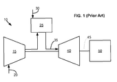
- Fig. 1 shows a schematic view of a gas turbine engine 10 as may be used herein.
- the gas turbine engine 10 may include a compressor 15.
- the compressor 15 may compress an incoming flow of air 20.
- the compressor 15 may deliver the compressed flow of air 20 to a combustor 25.
- the combustor 25 may mix the compressed flow of air 20 with a pressurized flow of fuel 30 and ignite the mixture to create a flow of combustion gases 35.
- the gas turbine engine 10 may include any number of combustors 25.
- the flow of combustion gases 35 is in turn delivered to a turbine 40.
- the flow of combustion gases 35 may drive the turbine 40 so as to produce mechanical work.
- the mechanical work produced in the turbine 40 may drive the compressor 15 via a shaft 45 and an external load 50 such as an electrical generator or the like.
- the gas turbine engine 10 may use natural gas, various types of syngas, and/or other types of fuels.
- the gas turbine engine 10 may be any one of a number of different gas turbine engines offered by General Electric Company of Schenectady, New York, including, but not limited to, those such as a 7 or a 9 series heavy duty gas turbine engine and the like.
- the gas turbine engine 10 may have different configurations and may use other types of components.
- gas turbine engines may also be used herein.
- multiple gas turbine engines, other types of turbines, and other types of power generation equipment may be used herein together.
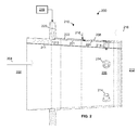
- Fig. 2 depicts an embodiment of a LLI combustor assembly 200 of the present application for facilitating LLI premixing.
- the LLI combustor assembly 200 may include a first interior 202 in which a first fuel supplied thereto is combustible.
- the first interior 202 may be a primary combustion zone of a combustor.
- the first fuel may be a primary fuel that is injected into the primary combustion zone.
- the primary fuel may be premixed with a compressor discharge air before, during, or after being injected into the primary combustion zone.
- one or more premixing nozzles may inject the first fuel, having been premixed, into the first interior 202.
- the first fuel may be injected directly into the first interior 202.
- the first interior 202 may include a flow of primary combustion gases 204 from the primary combustion zone.
- the first interior 202 and the associated combustor components for creating the primary combustion gasses 204 are not illustrated in detail. That is, any number of combustor or nozzle arrangements may be used to provide the primary combustion gases 204.
- a flow sleeve annulus 210 may connect the first interior 202 with a transition piece 212.
- the transition piece 212 may direct the contents of the combustor assembly 200 to a turbine (not shown).
- the flow sleeve annulus 210 may include a liner 211 forming a passageway for a cooling flow 213.
- the cooling flow may include, among other things, compressor discharge air 216.
- the flow sleeve annulus 210 may include a second interior 206 in which a second fuel 215 (having been mixed with air) may be supplied.
- the second fuel 215 may be supplied to the second interior 206 via a fuel manifold 220 and associated fuel conduit 221 disposed about the flow sleeve annulus 210.
- the first fuel and the second fuel may initiate from the same source or different sources.
- the first fuel and the second fuel may be the same, dissimilar, or any combination thereof.
- the first fuel and the second fuel may be any fuel.
- one or more fuel injectors 214 may be structurally supported by the flow sleeve annulus 210.
- the fuel injectors 214 may be disposed about the second interior 202 and may be configured to supply the second fuel 215 (having been mixed with air) to the second interior 206.
- the fuel injectors 214 may be disposed about the second interior 206 in any one of a single axial stage, multiple axial stages, a single axial circumferential stage, multiple axial circumferential stages, or the like. In this manner, the fuel injectors 214 may supply the second fuel 215 to the second interior 206 in a direction that is substantially traverse to a predominant flow of the flow sleeve annulus 210. Any number, type, or arrangement of fuel injector nozzles 214 may be used.
- At least one elongate premixing conduit 208 may be disposed about the flow sleeve annulus 210.
- the elongate premixing conduit 208 may include any passageway, channel, slot, duct, or the like that facilitates the mixing of fuel and air.
- the elongate premixing conduit 208 may be formed between an inner and outer wall of the flow sleeve annulus 210 and may extend wholly or partially along the axial length of the flow sleeve annulus 210.
- the elongate premixing conduit 208 may be in fluid communication with the fuel injectors 214, a compressor discharge air 216, and the second fuel 215.
- the compressor discharge air 216 and the second fuel 215 may be premixed within the elongate premixing conduit 208 before entering the second interior 206 by way of the fuel injectors 214.
- the fuel manifold 220 may be in fluid communication with the elongate premixing conduit 208 via the fuel conduit 221 for supplying the second fuel 215 to the elongate premixing conduit 208, as denoted by the dotted line 222.
- Compressor discharge air 216 may enter the elongate premixing conduit 208 at inlet 218 such that the second fuel 215 and the compressor discharge air 216 may be premixed within the elongate premixing conduit 208 thereby forming an air/fuel mixture as denoted by dashed line 224. Accordingly, in this embodiment, a portion of the axial length of the flow sleeve annulus 210 may be utilized to premix the second fuel 215 with the compressor discharge air 216. The premixed air/fuel mixture may then be directed into the second interior 206 by the fuel injector nozzles 214.
- the second fuel 215 and the compressor discharge air 216 may be supplied to the elongate premixing conduit 208 by any number of circuit arrangements.
- the LLI combustor assembly 200 may include one or more fuel conduits 221 (or feeds) in fluid communication with the elongate premixing conduit 208 and/or one or more compressor discharge air inlets 218 (or feeds) in fluid communication with the elongate premixing conduit 208.
- any number or combination of conduits or passageways may be used to supply the fuel 215 and/or air 216 to the elongate premixing conduits 208.
- any number or combination of elongate premixing conduits 208 may be used.
- the transition piece 212 may also include a similar configuration for facilitating LLI premixing. That is, the transition piece may include any number or combination of fuel manifolds, fuel conduits, air inlets, elongate premixing conduits, fuel injectors, or the like disposed about the transition piece 212 in a similar fashion to the flow sleeve annulus 210 described above.
- FIG. 3 illustrates an example flow diagram of a method 300 for facilitating late lean injection.
- the method 300 may begin at block 302 of FIG. 3 in which the method 300 may include providing a first fuel to a first interior of a combustor.
- the first interior may be a primary combustion zone of a combustor.
- the method 300 may include providing a second fuel to at least one elongate premixing conduit disposed about a flow sleeve annulus.
- the second fuel may be supplied to the elongate premixing conduit via a fuel manifold and associated fuel conduit disposed about the flow sleeve annulus.
- the method 300 may include providing compressor discharge air to the at least one elongate premixing conduit.
- the compressor discharge air may be provided to the elongate premixing conduit via any number of openings or slots about the elongate premixing conduit.
- the compressor discharge air may be provided before and/or after the second fuel enters the elongate premixing conduit.
- the method 300 may include premixing the second fuel with the compressor discharge air within the at least one elongate premixing conduit. In this manner, the second fuel and the compressor discharge air may be mixed along the axial length of all or part of the flow sleeve annulus.
- the method 300 may include injecting the premixed second fuel/compressor discharge air into a second interior of the combustor with at least one fuel injector.
Landscapes
- Engineering & Computer Science (AREA)
- Chemical & Material Sciences (AREA)
- Combustion & Propulsion (AREA)
- Mechanical Engineering (AREA)
- General Engineering & Computer Science (AREA)
Abstract
Description
- Embodiments of the present application relate generally to gas turbine engines and more particularly to combustor assemblies including late lean injection (LLI) premixing.
- In gas turbine engines, mixtures of fuel and gas are combusted within a combustor disposed upstream from a transition piece and a turbine. The combustor produces high energy fluids from which mechanical energy can be derived for the generation of power and electricity. The high energy fluids are continually reused until significant levels of power generation cannot be derived at which point they are exhausted into the atmosphere. This exhaust often includes pollutants produced during the combustion, such as nitrous oxides (NOx) and carbon monoxide (CO).
- Efforts have been expended to reduce the amount of pollutants produced by the combustion processes and include the development of LLI. LLI involves the injection of combustible materials into the flow of the high energy fluids at a location downstream from the normal combustion zone in the combustor. This downstream location could be defined as a section of the combustor liner or at a section of the transition piece. In any case, the combustible materials injected at this location increase the temperature and energy of the high energy fluids and lead to an increased consumption of CO with little to no significant increase in NOx for reasonable levels of LLI fuel flow.
- Some or all of the above needs and/or problems may be addressed by certain embodiments of the present application. According to one embodiment, there is disclosed a LLI combustor assembly. The LLI combustor assembly may include a first interior in which a first fuel supplied thereto is combustible. The LLI combustor assembly may also include a flow sleeve annulus including a second interior in which a second fuel supplied thereto is combustible. The flow sleeve annulus may fluidly couple the first interior and the second interior. The LLI combustor assembly may also include at least one fuel injector disposed about the second interior. The at least one fuel injector may be configured to supply the second fuel to the second interior. The LLI combustor assembly may also include at least one elongate premixing conduit disposed about the flow sleeve annulus and in fluid communication with the at least one fuel injector. In this manner, the at least one elongate premixing conduit may be in fluid communication with a compressor discharge air and the second fuel such that the compressor discharge air and the second fuel are premixed within the elongate premixing conduit before entering the second interior by way of the at least one fuel injector.
- According to another embodiment, there is disclosed a gas turbine engine assembly. The gas turbine engine assembly may include a combustor having a first interior in which a first fuel supplied thereto is combustible. The gas turbine engine assembly may also include a turbine that receives the products of at least the combustion of the first fuel. The gas turbine engine assembly may also include a flow sleeve annulus including a second interior in which a second fuel supplied thereto and the products of the combustion of the first fuel are combustible. The flow sleeve annulus may fluidly couple the combustor and the turbine. The gas turbine engine assembly may also include at least one fuel injector disposed about the second interior and configured to supply the second fuel to the second interior. The gas turbine engine assembly may also include at least one elongate premixing conduit disposed about the flow sleeve annulus and in fluid communication with the at least one fuel injector. In this manner, the at least one elongate premixing conduit may be in fluid communication with a compressor discharge air and the second fuel such that the compressor discharge air and the second fuel are premixed within the elongate premixing conduit before entering the second interior by way of the at least one fuel injector.
- Further, according to another embodiment, there is disclosed a method for facilitating LLI. The method may include providing a first fuel to a first interior of a combustor. The method may also include providing a second fuel to at least one elongate premixing conduit disposed about a flow sleeve annulus. The method may also include providing compressor discharge air to the at least one elongate premixing conduit. The method may also include premixing the second fuel with the compressor discharge air within the at least one elongate premixing conduit. The method may also include injecting the premixed second fuel/compressor discharge air into a second interior of the combustor with at least one fuel injector.
- Other embodiments, aspects, and features of the invention will become apparent to those skilled in the art from the following detailed description, the accompanying drawings, and the appended claims.
- Reference will now be made to the accompanying drawings, which are not necessarily drawn to scale, and wherein:
-
FIG. 1 is a schematic of an example diagram of a gas turbine engine with a compressor, a combustor, and a turbine. -
FIG. 2 is a cross-sectional view of a portion of a combustor assembly, according to an embodiment. -
FIG. 3 is an example flow diagram of a method, according to an embodiment. - Illustrative embodiments will now be described more fully hereinafter with reference to the accompanying drawings, in which some, but not all embodiments are shown. The present application may be embodied in many different forms and should not be construed as limited to the embodiments set forth herein. Like numbers refer to like elements throughout.
- Illustrative embodiments are directed to, among other things, a combustor assembly including LLI premixing.
Fig. 1 shows a schematic view of agas turbine engine 10 as may be used herein. As is known, thegas turbine engine 10 may include acompressor 15. Thecompressor 15 may compress an incoming flow ofair 20. Thecompressor 15 may deliver the compressed flow ofair 20 to acombustor 25. Thecombustor 25 may mix the compressed flow ofair 20 with a pressurized flow offuel 30 and ignite the mixture to create a flow ofcombustion gases 35. Although only asingle combustor 25 is shown, thegas turbine engine 10 may include any number ofcombustors 25. The flow ofcombustion gases 35 is in turn delivered to aturbine 40. The flow ofcombustion gases 35 may drive theturbine 40 so as to produce mechanical work. The mechanical work produced in theturbine 40 may drive thecompressor 15 via ashaft 45 and anexternal load 50 such as an electrical generator or the like. - The
gas turbine engine 10 may use natural gas, various types of syngas, and/or other types of fuels. Thegas turbine engine 10 may be any one of a number of different gas turbine engines offered by General Electric Company of Schenectady, New York, including, but not limited to, those such as a 7 or a 9 series heavy duty gas turbine engine and the like. Thegas turbine engine 10 may have different configurations and may use other types of components. - Other types of gas turbine engines may also be used herein. Moreover, multiple gas turbine engines, other types of turbines, and other types of power generation equipment may be used herein together.
-
Fig. 2 depicts an embodiment of aLLI combustor assembly 200 of the present application for facilitating LLI premixing. The LLIcombustor assembly 200 may include afirst interior 202 in which a first fuel supplied thereto is combustible. For example, thefirst interior 202 may be a primary combustion zone of a combustor. In this manner, the first fuel may be a primary fuel that is injected into the primary combustion zone. In some instances, the primary fuel may be premixed with a compressor discharge air before, during, or after being injected into the primary combustion zone. For example, one or more premixing nozzles may inject the first fuel, having been premixed, into thefirst interior 202. In other instances, the first fuel may be injected directly into thefirst interior 202. Accordingly, thefirst interior 202 may include a flow ofprimary combustion gases 204 from the primary combustion zone. Thefirst interior 202 and the associated combustor components for creating theprimary combustion gasses 204 are not illustrated in detail. That is, any number of combustor or nozzle arrangements may be used to provide theprimary combustion gases 204. - Still referring to
Fig. 2 , in an embodiment, aflow sleeve annulus 210 may connect thefirst interior 202 with atransition piece 212. Thetransition piece 212 may direct the contents of thecombustor assembly 200 to a turbine (not shown). In some instances, theflow sleeve annulus 210 may include aliner 211 forming a passageway for acooling flow 213. The cooling flow may include, among other things,compressor discharge air 216. Theflow sleeve annulus 210 may include asecond interior 206 in which a second fuel 215 (having been mixed with air) may be supplied. For example, in certain embodiments, thesecond fuel 215 may be supplied to thesecond interior 206 via afuel manifold 220 and associatedfuel conduit 221 disposed about theflow sleeve annulus 210. The first fuel and the second fuel may initiate from the same source or different sources. Moreover, the first fuel and the second fuel may be the same, dissimilar, or any combination thereof. Indeed, the first fuel and the second fuel may be any fuel. - In one embodiment, one or
more fuel injectors 214 may be structurally supported by theflow sleeve annulus 210. Thefuel injectors 214 may be disposed about thesecond interior 202 and may be configured to supply the second fuel 215 (having been mixed with air) to thesecond interior 206. Thefuel injectors 214 may be disposed about thesecond interior 206 in any one of a single axial stage, multiple axial stages, a single axial circumferential stage, multiple axial circumferential stages, or the like. In this manner, thefuel injectors 214 may supply thesecond fuel 215 to thesecond interior 206 in a direction that is substantially traverse to a predominant flow of theflow sleeve annulus 210. Any number, type, or arrangement offuel injector nozzles 214 may be used. - In certain aspects, at least one
elongate premixing conduit 208 may be disposed about theflow sleeve annulus 210. Theelongate premixing conduit 208 may include any passageway, channel, slot, duct, or the like that facilitates the mixing of fuel and air. For example, in some instances, theelongate premixing conduit 208 may be formed between an inner and outer wall of theflow sleeve annulus 210 and may extend wholly or partially along the axial length of theflow sleeve annulus 210. - In an embodiment, the
elongate premixing conduit 208 may be in fluid communication with thefuel injectors 214, acompressor discharge air 216, and thesecond fuel 215. In this manner, thecompressor discharge air 216 and thesecond fuel 215 may be premixed within theelongate premixing conduit 208 before entering thesecond interior 206 by way of thefuel injectors 214. For example, thefuel manifold 220 may be in fluid communication with theelongate premixing conduit 208 via thefuel conduit 221 for supplying thesecond fuel 215 to theelongate premixing conduit 208, as denoted by the dottedline 222.Compressor discharge air 216 may enter theelongate premixing conduit 208 atinlet 218 such that thesecond fuel 215 and thecompressor discharge air 216 may be premixed within theelongate premixing conduit 208 thereby forming an air/fuel mixture as denoted by dashedline 224. Accordingly, in this embodiment, a portion of the axial length of theflow sleeve annulus 210 may be utilized to premix thesecond fuel 215 with thecompressor discharge air 216. The premixed air/fuel mixture may then be directed into thesecond interior 206 by thefuel injector nozzles 214. - The
second fuel 215 and thecompressor discharge air 216 may be supplied to theelongate premixing conduit 208 by any number of circuit arrangements. For example, theLLI combustor assembly 200 may include one or more fuel conduits 221 (or feeds) in fluid communication with theelongate premixing conduit 208 and/or one or more compressor discharge air inlets 218 (or feeds) in fluid communication with theelongate premixing conduit 208. In this manner, any number or combination of conduits or passageways may be used to supply thefuel 215 and/orair 216 to theelongate premixing conduits 208. Moreover, any number or combination ofelongate premixing conduits 208 may be used. - The
transition piece 212 may also include a similar configuration for facilitating LLI premixing. That is, the transition piece may include any number or combination of fuel manifolds, fuel conduits, air inlets, elongate premixing conduits, fuel injectors, or the like disposed about thetransition piece 212 in a similar fashion to theflow sleeve annulus 210 described above. -
FIG. 3 illustrates an example flow diagram of amethod 300 for facilitating late lean injection. In this particular embodiment, themethod 300 may begin atblock 302 ofFIG. 3 in which themethod 300 may include providing a first fuel to a first interior of a combustor. For example, the first interior may be a primary combustion zone of a combustor. Atblock 304, themethod 300 may include providing a second fuel to at least one elongate premixing conduit disposed about a flow sleeve annulus. For example, the second fuel may be supplied to the elongate premixing conduit via a fuel manifold and associated fuel conduit disposed about the flow sleeve annulus. Atblock 306, themethod 300 may include providing compressor discharge air to the at least one elongate premixing conduit. The compressor discharge air may be provided to the elongate premixing conduit via any number of openings or slots about the elongate premixing conduit. For example, the compressor discharge air may be provided before and/or after the second fuel enters the elongate premixing conduit. Atblock 308, themethod 300 may include premixing the second fuel with the compressor discharge air within the at least one elongate premixing conduit. In this manner, the second fuel and the compressor discharge air may be mixed along the axial length of all or part of the flow sleeve annulus. Atblock 310, themethod 300 may include injecting the premixed second fuel/compressor discharge air into a second interior of the combustor with at least one fuel injector. - Although embodiments have been described in language specific to structural features and/or methodological acts, it is to be understood that the disclosure is not necessarily limited to the specific features or acts described. Rather, the specific features and acts are disclosed as illustrative forms of implementing the embodiments.
Claims (12)
- A late lean injection combustor assembly (200) including a first fuel, a second fuel (215), and compressor discharge air (216), the late lean injection combustor assembly (200) comprising:a first interior (202) in which the first fuel supplied thereto is combustible;a flow sleeve annulus (210) comprising a second interior (206) in which the second fuel (215) supplied thereto is combustible, the flow sleeve annulus (210) fluidly coupling the first interior (202) and the second interior (206);at least one fuel injector (214) disposed about the second interior (206), the at least one fuel injector (214) configured to supply the second fuel (215) to the second interior (206);at least one elongate premixing conduit (208) disposed about the flow sleeve annulus (210) and in fluid communication with the at least one fuel injector (214); andthe at least one elongate premixing conduit (208) being in fluid communication with the compressor discharge air (216) and the second fuel (215) such that the compressor discharge air (216) and the second fuel are premixed within the elongate premixing conduit (208) before entering the second interior (206) by way of the at least one fuel injector (214).
- The late lean injection combustor assembly of claim 1, further comprising a fuel manifold (220) inlet (218) disposed about the flow sleeve annulus (206), the fuel manifold inlet (218) being in fluid communication with the at least one elongate premixing conduit (208) for supplying the second fuel (215) thereto.
- The late lean injection combustor assembly of claim 1 or 2, further comprising one or more fuel injection feeds (221) in fluid communication with the at least one elongate premixing conduit (208).
- The late lean injection combustor assembly of any of claims 1 to 3, further comprising one or more compressor discharge air feeds (218) in fluid communication with the at least one elongate premixing conduit (208).
- The late lean injection combustor assembly of any of claims 1 to 4, wherein the second fuel (215) is injected into the at least one elongate premixing conduit (208) before the compressor discharge air (216).
- The late lean injection combustor assembly of any preceding claim, wherein the second fuel (215) is injected into the at least one elongate premixing conduit (208) after the compressor discharge air (216).
- The late lean injection combustor assembly of any preceding claim, wherein the at least one fuel injector (214) is disposed about the second interior (206) in any one of a single axial stage, multiple axial stages, a single axial circumferential stage, or multiple axial circumferential stages.
- The late lean injection combustor assembly of any preceding claim, further comprising one or more premixing nozzles to inject the first fuel, having been premixed, into the first interior (202).
- The late lean injection combustor assembly of any preceding claim, wherein the at least one fuel injector (214) supplies the second fuel (215) to the second interior (206) in a direction that is substantially traverse to a predominant flow of the flow sleeve annulus (210).
- A gas turbine engine assembly (10), comprising: the late lean injection combustor assembly (200) of any preceding claim; and
a combustor (25) having the first interior (202);
a turbine (40) that receives the products of at least the combustion of the first fuel;
wherein the flow sleeve annulus (210) fluidly couples the combustor (25) and the turbine (40). - A method (300) for late lean injection, comprising:providing (302) a first fuel to a first interior (202) of a combustor (25);providing (304) a second fuel (215) to at least one elongate premixing conduit (208) disposed about a flow sleeve annulus (200);providing (306) compressor discharge air (216) to the at least one elongate premixing conduit (208);premixing (308) the second fuel (215) with the compressor discharge air (216) within the at least one elongate premixing conduit (208); andinjecting (310) the premixed second fuel (215)/compressor discharge air (216) into a second interior (206) of the combustor (25) with at least one fuel injector (214).
- The method of claim 11, further comprising premixing the first fuel with a compressor discharge (216).
Applications Claiming Priority (1)
| Application Number | Priority Date | Filing Date | Title |
|---|---|---|---|
| US13/716,821 US9404659B2 (en) | 2012-12-17 | 2012-12-17 | Systems and methods for late lean injection premixing |
Publications (2)
| Publication Number | Publication Date |
|---|---|
| EP2743586A2 true EP2743586A2 (en) | 2014-06-18 |
| EP2743586A3 EP2743586A3 (en) | 2014-08-20 |
Family
ID=49753073
Family Applications (1)
| Application Number | Title | Priority Date | Filing Date |
|---|---|---|---|
| EP13196758.0A Withdrawn EP2743586A3 (en) | 2012-12-17 | 2013-12-11 | Systems and methods for late lean injection premixing |
Country Status (4)
| Country | Link |
|---|---|
| US (1) | US9404659B2 (en) |
| EP (1) | EP2743586A3 (en) |
| JP (1) | JP2014119250A (en) |
| CN (1) | CN203907670U (en) |
Families Citing this family (10)
| Publication number | Priority date | Publication date | Assignee | Title |
|---|---|---|---|---|
| US6541083B1 (en) | 2000-01-11 | 2003-04-01 | Guardian Industries Corp. | Vacuum IG unit with alkali silicate edge seal and/or spacers |
| US9140455B2 (en) * | 2012-01-04 | 2015-09-22 | General Electric Company | Flowsleeve of a turbomachine component |
| US20150159877A1 (en) * | 2013-12-06 | 2015-06-11 | General Electric Company | Late lean injection manifold mixing system |
| US10788212B2 (en) * | 2015-01-12 | 2020-09-29 | General Electric Company | System and method for an oxidant passageway in a gas turbine system with exhaust gas recirculation |
| US9897322B2 (en) * | 2015-07-07 | 2018-02-20 | General Electric Company | Combustor assembly for a gas turbine engine and method of making same |
| CN105042637A (en) * | 2015-07-09 | 2015-11-11 | 中国航空工业集团公司沈阳发动机设计研究所 | Combustion chamber |
| EP3228937B1 (en) * | 2016-04-08 | 2018-11-07 | Ansaldo Energia Switzerland AG | Method for combusting a fuel, and combustion device |
| US11156164B2 (en) | 2019-05-21 | 2021-10-26 | General Electric Company | System and method for high frequency accoustic dampers with caps |
| US11174792B2 (en) | 2019-05-21 | 2021-11-16 | General Electric Company | System and method for high frequency acoustic dampers with baffles |
| US11933216B2 (en) * | 2022-01-04 | 2024-03-19 | General Electric Company | Systems and methods for providing output products to a combustion chamber of a gas turbine engine |
Citations (1)
| Publication number | Priority date | Publication date | Assignee | Title |
|---|---|---|---|---|
| US6732527B2 (en) * | 2001-05-15 | 2004-05-11 | Rolls-Royce Plc | Combustion chamber |
Family Cites Families (36)
| Publication number | Priority date | Publication date | Assignee | Title |
|---|---|---|---|---|
| US4581581A (en) | 1983-06-30 | 1986-04-08 | General Electric Company | Method of projection reconstruction imaging with reduced sensitivity to motion-related artifacts |
| US4843884A (en) | 1986-11-06 | 1989-07-04 | Gas Research Institute | Method and system for ultrasonic detection of flaws in test objects |
| GB2233094B (en) | 1989-05-26 | 1994-02-09 | Circulation Res Ltd | Methods and apparatus for the examination and treatment of internal organs |
| FR2662525B1 (en) | 1990-05-25 | 1992-08-28 | Gen Electric Cgr | METHOD FOR VISUALIZATION OF A PART OF THE IMAGE OF A PHYSICAL STRUCTURE. |
| JP3109749B2 (en) | 1991-04-17 | 2000-11-20 | 株式会社東芝 | Ultrasound imaging device |
| JP3335713B2 (en) * | 1993-06-28 | 2002-10-21 | 株式会社東芝 | Gas turbine combustor |
| GB2284884B (en) * | 1993-12-16 | 1997-12-10 | Rolls Royce Plc | A gas turbine engine combustion chamber |
| US5544655A (en) | 1994-09-16 | 1996-08-13 | Atlantis Diagnostics International, Llc | Ultrasonic multiline beamforming with interleaved sampling |
| US5647215A (en) | 1995-11-07 | 1997-07-15 | Westinghouse Electric Corporation | Gas turbine combustor with turbulence enhanced mixing fuel injectors |
| JPH09238944A (en) | 1996-03-13 | 1997-09-16 | Fujitsu Ltd | Ultrasound diagnostic equipment |
| US20010049932A1 (en) | 1996-05-02 | 2001-12-13 | Beebe Kenneth W. | Premixing dry low NOx emissions combustor with lean direct injection of gas fuel |
| US5991239A (en) | 1996-05-08 | 1999-11-23 | Mayo Foundation For Medical Education And Research | Confocal acoustic force generator |
| US6171247B1 (en) | 1997-06-13 | 2001-01-09 | Mayo Foundation For Medical Education And Research | Underfluid catheter system and method having a rotatable multiplane transducer |
| US6556695B1 (en) | 1999-02-05 | 2003-04-29 | Mayo Foundation For Medical Education And Research | Method for producing high resolution real-time images, of structure and function during medical procedures |
| GB0019533D0 (en) * | 2000-08-10 | 2000-09-27 | Rolls Royce Plc | A combustion chamber |
| JP4309683B2 (en) | 2002-03-25 | 2009-08-05 | オリンパス株式会社 | Ultrasound observation system |
| US7618373B2 (en) | 2003-02-14 | 2009-11-17 | Siemens Medical Solutions Usa, Inc. | Microfabricated ultrasonic transducer array for 3-D imaging and method of operating the same |
| WO2005009244A1 (en) | 2003-07-24 | 2005-02-03 | HER MAJESTY THE QUEEN IN RIGHT OF CANADA asrepres ented by THE MINISTER OF NATIONAL DEFENSE | Non-invasive monitoring of intracranial dynamic effects and brain density fluctuations |
| JP4286621B2 (en) | 2003-09-19 | 2009-07-01 | 富士フイルム株式会社 | Ultrasonic transceiver |
| US7542544B2 (en) | 2004-01-06 | 2009-06-02 | The Regents Of The University Of Michigan | Ultrasound gating of cardiac CT scans |
| US7324910B2 (en) | 2005-12-22 | 2008-01-29 | General Electric Company | Sensor array for navigation on surfaces |
| US20070239020A1 (en) | 2006-01-19 | 2007-10-11 | Kazuhiro Iinuma | Ultrasonography apparatus |
| US7751989B2 (en) | 2006-11-30 | 2010-07-06 | Fbs, Inc. | Guided wave pipeline inspection system with enhanced focusing capability |
| US7970214B2 (en) | 2007-01-25 | 2011-06-28 | University Of Utah Research Foundation | Rotate and slant projector for fast fully-3D iterative tomographic reconstruction |
| US20090048789A1 (en) | 2007-04-13 | 2009-02-19 | University Of South Carolina | Optimized Embedded Ultrasonics Structural Radar System With Piezoelectric Wafer Active Sensor Phased Arrays For In-Situ Wide-Area Damage Detection |
| WO2008141301A1 (en) | 2007-05-10 | 2008-11-20 | Veeco Instruments Inc. | Non-destructive wafer-scale sub-surface ultrasonic microscopy employing near field afm detection |
| DE102007028876A1 (en) | 2007-06-20 | 2009-05-07 | Ge Inspection Technologies Gmbh | Method for nondestructive detection of a rotational movement on the surface of a test object, device for this purpose, and test unit |
| JP5208124B2 (en) | 2007-11-15 | 2013-06-12 | 国立大学法人北海道大学 | Ultrasonic multiphase flow meter, ultrasonic multiphase flow measurement program, and multiphase flow measurement method using ultrasonic |
| DE102008002445B4 (en) | 2008-01-04 | 2017-12-28 | Ge Inspection Technologies Gmbh | Method for the non-destructive testing of a test specimen by means of ultrasound and device for this purpose |
| DE102008037173A1 (en) | 2008-01-04 | 2009-07-09 | Ge Inspection Technologies Gmbh | Method for the non-destructive testing of a specimen by means of ultrasound and devices therefor |
| JP4999776B2 (en) | 2008-05-19 | 2012-08-15 | 中部電力株式会社 | Defect evaluation method for long member and defect evaluation apparatus for long member |
| US8701383B2 (en) | 2009-01-07 | 2014-04-22 | General Electric Company | Late lean injection system configuration |
| CA2705731A1 (en) | 2009-02-23 | 2010-08-23 | Sunnybrook Health Sciences Centre | Method for automatic segmentation of images |
| JP5508765B2 (en) | 2009-06-03 | 2014-06-04 | 株式会社東芝 | 3D ultrasonic diagnostic equipment |
| DE102009030721B4 (en) | 2009-06-26 | 2013-04-04 | Siemens Aktiengesellschaft | SAR calculation for multi-channel MR transmission systems |
| US8316714B2 (en) | 2009-07-22 | 2012-11-27 | Siemens Medical Solutions Usa, Inc. | Scan patterns for electronically positioned apertures on an array |
-
2012
- 2012-12-17 US US13/716,821 patent/US9404659B2/en active Active
-
2013
- 2013-12-11 EP EP13196758.0A patent/EP2743586A3/en not_active Withdrawn
- 2013-12-13 JP JP2013257550A patent/JP2014119250A/en active Pending
- 2013-12-17 CN CN201320833334.8U patent/CN203907670U/en not_active Expired - Fee Related
Patent Citations (1)
| Publication number | Priority date | Publication date | Assignee | Title |
|---|---|---|---|---|
| US6732527B2 (en) * | 2001-05-15 | 2004-05-11 | Rolls-Royce Plc | Combustion chamber |
Also Published As
| Publication number | Publication date |
|---|---|
| US20140165577A1 (en) | 2014-06-19 |
| EP2743586A3 (en) | 2014-08-20 |
| CN203907670U (en) | 2014-10-29 |
| US9404659B2 (en) | 2016-08-02 |
| JP2014119250A (en) | 2014-06-30 |
Similar Documents
| Publication | Publication Date | Title |
|---|---|---|
| US9404659B2 (en) | Systems and methods for late lean injection premixing | |
| US9074773B2 (en) | Combustor assembly with trapped vortex cavity | |
| US9212822B2 (en) | Fuel injection assembly for use in turbine engines and method of assembling same | |
| US8863525B2 (en) | Combustor with fuel staggering for flame holding mitigation | |
| US9151500B2 (en) | System for supplying a fuel and a working fluid through a liner to a combustion chamber | |
| CN107923620B (en) | System and method for multi-fuel premixing nozzle with integral liquid injector/evaporator | |
| EP2613091B1 (en) | Flowsleeve of a turbomachine component | |
| EP2664854A2 (en) | Secondary combustion system | |
| US8893501B2 (en) | Combustor crossfire tube | |
| US11371709B2 (en) | Combustor air flow path | |
| US9068750B2 (en) | Combustor with a pre-nozzle mixing cap assembly | |
| EP2618052A1 (en) | Fuel Nozzle | |
| US20130227928A1 (en) | Fuel nozzle assembly for use in turbine engines and method of assembling same | |
| US20140260302A1 (en) | DIFFUSION COMBUSTOR FUEL NOZZLE FOR LIMITING NOx EMISSIONS | |
| US20180245792A1 (en) | Combustion System with Axially Staged Fuel Injection | |
| US20130199190A1 (en) | Fuel injection assembly for use in turbine engines and method of assembling same | |
| US20240263590A1 (en) | Fuel system with pilot and main injectors for hydrogen-driven gas turbine engine | |
| US20250067436A1 (en) | Ammonia combustor | |
| EP2626632A2 (en) | Fuel injection assembly for use in turbine engines and method of assembling same | |
| US9500367B2 (en) | Combustion casing manifold for high pressure air delivery to a fuel nozzle pilot system |
Legal Events
| Date | Code | Title | Description |
|---|---|---|---|
| PUAI | Public reference made under article 153(3) epc to a published international application that has entered the european phase |
Free format text: ORIGINAL CODE: 0009012 |
|
| 17P | Request for examination filed |
Effective date: 20131211 |
|
| AK | Designated contracting states |
Kind code of ref document: A2 Designated state(s): AL AT BE BG CH CY CZ DE DK EE ES FI FR GB GR HR HU IE IS IT LI LT LU LV MC MK MT NL NO PL PT RO RS SE SI SK SM TR |
|
| AX | Request for extension of the european patent |
Extension state: BA ME |
|
| PUAL | Search report despatched |
Free format text: ORIGINAL CODE: 0009013 |
|
| AK | Designated contracting states |
Kind code of ref document: A3 Designated state(s): AL AT BE BG CH CY CZ DE DK EE ES FI FR GB GR HR HU IE IS IT LI LT LU LV MC MK MT NL NO PL PT RO RS SE SI SK SM TR |
|
| AX | Request for extension of the european patent |
Extension state: BA ME |
|
| RIC1 | Information provided on ipc code assigned before grant |
Ipc: F23R 3/34 20060101ALI20140714BHEP Ipc: F23R 3/28 20060101ALI20140714BHEP Ipc: F23R 3/06 20060101AFI20140714BHEP |
|
| R17P | Request for examination filed (corrected) |
Effective date: 20150220 |
|
| RBV | Designated contracting states (corrected) |
Designated state(s): AL AT BE BG CH CY CZ DE DK EE ES FI FR GB GR HR HU IE IS IT LI LT LU LV MC MK MT NL NO PL PT RO RS SE SI SK SM TR |
|
| 17Q | First examination report despatched |
Effective date: 20150722 |
|
| GRAP | Despatch of communication of intention to grant a patent |
Free format text: ORIGINAL CODE: EPIDOSNIGR1 |
|
| INTG | Intention to grant announced |
Effective date: 20160324 |
|
| STAA | Information on the status of an ep patent application or granted ep patent |
Free format text: STATUS: THE APPLICATION IS DEEMED TO BE WITHDRAWN |
|
| 18D | Application deemed to be withdrawn |
Effective date: 20160804 |