EP2743576A2 - LED-Beleuchtungsvorrichtung mit unabhängig ein- oder ausschaltbaren LED-Gruppen - Google Patents
LED-Beleuchtungsvorrichtung mit unabhängig ein- oder ausschaltbaren LED-Gruppen Download PDFInfo
- Publication number
- EP2743576A2 EP2743576A2 EP20130196482 EP13196482A EP2743576A2 EP 2743576 A2 EP2743576 A2 EP 2743576A2 EP 20130196482 EP20130196482 EP 20130196482 EP 13196482 A EP13196482 A EP 13196482A EP 2743576 A2 EP2743576 A2 EP 2743576A2
- Authority
- EP
- European Patent Office
- Prior art keywords
- heat dissipation
- dissipation unit
- led
- leds
- lighting apparatus
- Prior art date
- Legal status (The legal status is an assumption and is not a legal conclusion. Google has not performed a legal analysis and makes no representation as to the accuracy of the status listed.)
- Granted
Links
Images

Classifications
-
- F—MECHANICAL ENGINEERING; LIGHTING; HEATING; WEAPONS; BLASTING
- F21—LIGHTING
- F21V—FUNCTIONAL FEATURES OR DETAILS OF LIGHTING DEVICES OR SYSTEMS THEREOF; STRUCTURAL COMBINATIONS OF LIGHTING DEVICES WITH OTHER ARTICLES, NOT OTHERWISE PROVIDED FOR
- F21V29/00—Protecting lighting devices from thermal damage; Cooling or heating arrangements specially adapted for lighting devices or systems
- F21V29/50—Cooling arrangements
- F21V29/70—Cooling arrangements characterised by passive heat-dissipating elements, e.g. heat-sinks
- F21V29/74—Cooling arrangements characterised by passive heat-dissipating elements, e.g. heat-sinks with fins or blades
- F21V29/76—Cooling arrangements characterised by passive heat-dissipating elements, e.g. heat-sinks with fins or blades with essentially identical parallel planar fins or blades, e.g. with comb-like cross-section
- F21V29/763—Cooling arrangements characterised by passive heat-dissipating elements, e.g. heat-sinks with fins or blades with essentially identical parallel planar fins or blades, e.g. with comb-like cross-section the planes containing the fins or blades having the direction of the light emitting axis
-
- F—MECHANICAL ENGINEERING; LIGHTING; HEATING; WEAPONS; BLASTING
- F21—LIGHTING
- F21K—NON-ELECTRIC LIGHT SOURCES USING LUMINESCENCE; LIGHT SOURCES USING ELECTROCHEMILUMINESCENCE; LIGHT SOURCES USING CHARGES OF COMBUSTIBLE MATERIAL; LIGHT SOURCES USING SEMICONDUCTOR DEVICES AS LIGHT-GENERATING ELEMENTS; LIGHT SOURCES NOT OTHERWISE PROVIDED FOR
- F21K2/00—Non-electric light sources using luminescence; Light sources using electrochemiluminescence
-
- F—MECHANICAL ENGINEERING; LIGHTING; HEATING; WEAPONS; BLASTING
- F21—LIGHTING
- F21S—NON-PORTABLE LIGHTING DEVICES; SYSTEMS THEREOF; VEHICLE LIGHTING DEVICES SPECIALLY ADAPTED FOR VEHICLE EXTERIORS
- F21S2/00—Systems of lighting devices, not provided for in main groups F21S4/00 - F21S10/00 or F21S19/00, e.g. of modular construction
- F21S2/005—Systems of lighting devices, not provided for in main groups F21S4/00 - F21S10/00 or F21S19/00, e.g. of modular construction of modular construction
-
- F—MECHANICAL ENGINEERING; LIGHTING; HEATING; WEAPONS; BLASTING
- F21—LIGHTING
- F21V—FUNCTIONAL FEATURES OR DETAILS OF LIGHTING DEVICES OR SYSTEMS THEREOF; STRUCTURAL COMBINATIONS OF LIGHTING DEVICES WITH OTHER ARTICLES, NOT OTHERWISE PROVIDED FOR
- F21V17/00—Fastening of component parts of lighting devices, e.g. shades, globes, refractors, reflectors, filters, screens, grids or protective cages
- F21V17/10—Fastening of component parts of lighting devices, e.g. shades, globes, refractors, reflectors, filters, screens, grids or protective cages characterised by specific fastening means or way of fastening
-
- F—MECHANICAL ENGINEERING; LIGHTING; HEATING; WEAPONS; BLASTING
- F21—LIGHTING
- F21V—FUNCTIONAL FEATURES OR DETAILS OF LIGHTING DEVICES OR SYSTEMS THEREOF; STRUCTURAL COMBINATIONS OF LIGHTING DEVICES WITH OTHER ARTICLES, NOT OTHERWISE PROVIDED FOR
- F21V17/00—Fastening of component parts of lighting devices, e.g. shades, globes, refractors, reflectors, filters, screens, grids or protective cages
- F21V17/10—Fastening of component parts of lighting devices, e.g. shades, globes, refractors, reflectors, filters, screens, grids or protective cages characterised by specific fastening means or way of fastening
- F21V17/107—Fastening of component parts of lighting devices, e.g. shades, globes, refractors, reflectors, filters, screens, grids or protective cages characterised by specific fastening means or way of fastening using hinge joints
-
- F—MECHANICAL ENGINEERING; LIGHTING; HEATING; WEAPONS; BLASTING
- F21—LIGHTING
- F21V—FUNCTIONAL FEATURES OR DETAILS OF LIGHTING DEVICES OR SYSTEMS THEREOF; STRUCTURAL COMBINATIONS OF LIGHTING DEVICES WITH OTHER ARTICLES, NOT OTHERWISE PROVIDED FOR
- F21V17/00—Fastening of component parts of lighting devices, e.g. shades, globes, refractors, reflectors, filters, screens, grids or protective cages
- F21V17/10—Fastening of component parts of lighting devices, e.g. shades, globes, refractors, reflectors, filters, screens, grids or protective cages characterised by specific fastening means or way of fastening
- F21V17/12—Fastening of component parts of lighting devices, e.g. shades, globes, refractors, reflectors, filters, screens, grids or protective cages characterised by specific fastening means or way of fastening by screwing
-
- F—MECHANICAL ENGINEERING; LIGHTING; HEATING; WEAPONS; BLASTING
- F21—LIGHTING
- F21V—FUNCTIONAL FEATURES OR DETAILS OF LIGHTING DEVICES OR SYSTEMS THEREOF; STRUCTURAL COMBINATIONS OF LIGHTING DEVICES WITH OTHER ARTICLES, NOT OTHERWISE PROVIDED FOR
- F21V23/00—Arrangement of electric circuit elements in or on lighting devices
- F21V23/04—Arrangement of electric circuit elements in or on lighting devices the elements being switches
-
- F—MECHANICAL ENGINEERING; LIGHTING; HEATING; WEAPONS; BLASTING
- F21—LIGHTING
- F21V—FUNCTIONAL FEATURES OR DETAILS OF LIGHTING DEVICES OR SYSTEMS THEREOF; STRUCTURAL COMBINATIONS OF LIGHTING DEVICES WITH OTHER ARTICLES, NOT OTHERWISE PROVIDED FOR
- F21V21/00—Supporting, suspending, or attaching arrangements for lighting devices; Hand grips
- F21V21/14—Adjustable mountings
- F21V21/30—Pivoted housings or frames
-
- F—MECHANICAL ENGINEERING; LIGHTING; HEATING; WEAPONS; BLASTING
- F21—LIGHTING
- F21V—FUNCTIONAL FEATURES OR DETAILS OF LIGHTING DEVICES OR SYSTEMS THEREOF; STRUCTURAL COMBINATIONS OF LIGHTING DEVICES WITH OTHER ARTICLES, NOT OTHERWISE PROVIDED FOR
- F21V31/00—Gas-tight or water-tight arrangements
- F21V31/005—Sealing arrangements therefor
-
- F—MECHANICAL ENGINEERING; LIGHTING; HEATING; WEAPONS; BLASTING
- F21—LIGHTING
- F21W—INDEXING SCHEME ASSOCIATED WITH SUBCLASSES F21K, F21L, F21S and F21V, RELATING TO USES OR APPLICATIONS OF LIGHTING DEVICES OR SYSTEMS
- F21W2131/00—Use or application of lighting devices or systems not provided for in codes F21W2102/00-F21W2121/00
- F21W2131/10—Outdoor lighting
-
- F—MECHANICAL ENGINEERING; LIGHTING; HEATING; WEAPONS; BLASTING
- F21—LIGHTING
- F21W—INDEXING SCHEME ASSOCIATED WITH SUBCLASSES F21K, F21L, F21S and F21V, RELATING TO USES OR APPLICATIONS OF LIGHTING DEVICES OR SYSTEMS
- F21W2131/00—Use or application of lighting devices or systems not provided for in codes F21W2102/00-F21W2121/00
- F21W2131/40—Lighting for industrial, commercial, recreational or military use
-
- F—MECHANICAL ENGINEERING; LIGHTING; HEATING; WEAPONS; BLASTING
- F21—LIGHTING
- F21Y—INDEXING SCHEME ASSOCIATED WITH SUBCLASSES F21K, F21L, F21S and F21V, RELATING TO THE FORM OR THE KIND OF THE LIGHT SOURCES OR OF THE COLOUR OF THE LIGHT EMITTED
- F21Y2105/00—Planar light sources
- F21Y2105/10—Planar light sources comprising a two-dimensional [2D] array of point-like light-generating elements
-
- F—MECHANICAL ENGINEERING; LIGHTING; HEATING; WEAPONS; BLASTING
- F21—LIGHTING
- F21Y—INDEXING SCHEME ASSOCIATED WITH SUBCLASSES F21K, F21L, F21S and F21V, RELATING TO THE FORM OR THE KIND OF THE LIGHT SOURCES OR OF THE COLOUR OF THE LIGHT EMITTED
- F21Y2115/00—Light-generating elements of semiconductor light sources
- F21Y2115/10—Light-emitting diodes [LED]
Definitions
- the present invention relates, in general, to LED lighting apparatuses used for landscape lighting, stage lighting, display lighting, task lighting, driving lighting, etc. and, more particularly, to an LED lighting apparatus having LED arrays turned on or off independently, in which LEDs of an LED module constitute a plurality of LED arrays that are independently turned on or off, so that, when an LED has a failure, only the LED array having the associated LED is turned off and other LED arrays are continuously turned on, thus preventing a problem from occurring in illumination, and in which waterproofing properties are enhanced, thus preventing moisture from permeating the LED module, and which makes it easy to adjust an illumination angle and to assemble components with each other.
- LEDs are relatively expensive, they are widely used as a light source of a lighting apparatus because the LEDs have many advantages, namely, high efficiency, environmental friendliness, semi-permanency, high luminance, etc.
- the LED is used.
- the lighting apparatus using LEDs utilizes an LED module having a plurality of LEDs mounted on a PCB.
- the LEDs of the LED module are usually connected to each other in series in terms of a circuit. If there are many LEDs, among the LEDs connected to each other in series, a predetermined number of LEDs may be connected to each other in parallel.
- the lighting apparatus for landscape lighting, stage lighting, display lighting, task lighting, driving lighting, etc. is installed at the exterior, it is likely to make contact with moisture such as rainwater. Furthermore, the LED that is a semiconductor device is vulnerable to moisture.
- a waterproofing property is very important in the lighting apparatus using the LED module.
- the related art does not concentrate on increasing the waterproofing property.
- the lighting apparatus which is installed at the exterior and used for landscape lighting, stage lighting, display lighting, task lighting, driving lighting, etc., frequently needs to adjust its illumination angle, and needs to be stably secured at the adjusted angle to continuously perform illumination at the adjusted angle without being affected by external shocks or vibrations.
- the present invention has been made keeping in mind the above problems occurring in the related art, and the present invention is intended to propose an LED lighting apparatus having LED arrays turned on or off independently, in which an LED module comprises a plurality of LED arrays that are independently turned on or off, so that, even if any individual LED has a problem, only the LED array having the associated LED is turned off and other LED arrays are continuously turned on, thus enabling stable illumination without interruption, and in which waterproofing properties are enhanced, thus preventing the LED, that is a semiconductor device vulnerable to moisture, from being in contact with the moisture and being damaged, thereby achieving high durability, and which makes it easy to adjust an illumination angle and can be stably fixed at the adjusted angle, thus realizing excellent illumination quality.
- an LED lighting apparatus having LED arrays turned on or off independently, the apparatus including:
- the LED lighting apparatus may further include a protective cover for covering the LED module; a mounting frame surrounding an edge of the protective cover, and mounted to a front edge of the heat dissipation unit; and a waterproof packing provided on a rear edge of the protective cover, and pressurized against the front of the heat dissipation unit, thus sealing a gap between the protective cover and the heat dissipation unit.
- the LED lighting apparatus may further include a light conversion plate having a collimated lens disposed in front of the LEDs of the LED module to convert light emitted from the LEDs into parallel beams; and a holder holding the collimated lens.
- the LED lighting apparatus may further include a first hinge hole formed in a vertical part of the locking bracket; a guide hole formed in the vertical part to have a shape of an arc around the first hinge hole; a second hinge hole formed in a side surface of the heat dissipation unit to correspond to the first hinge hole; a locking hole formed in the side surface of the heat dissipation unit to correspond to the guide hole; a hinge pin inserted into the first hinge hole and the second hinge hole to hingedly couple the locking bracket to the heat dissipation unit; and an angle adjusting means passing through the guide hole to be fastened to the locking hole, guiding rotation of the heat dissipation unit, and locking the heat dissipation unit to the locking bracket.
- the LED lighting apparatus having the LED arrays turned on or off independently is advantageous in that the LED module comprises the plurality of LED arrays that are independently turned on or off, so that, when any one of the LEDs has a problem, all of the LEDs are not affected negatively, but only the LED array having the defective LED is turned off and other LED arrays can stably continue an illuminating function, and in which waterproofing properties are enhanced, thus guaranteeing the illuminating function for a lengthy period of time without a damage resulting from moisture, and in which components are rapidly assembled with each other, thus achieving high productivity, and in which light beams emitted from the LED are radiated in parallel via a collimated lens, thus realizing excellent illumination quality. Consequently, this apparatus is very useful in industrial applications.
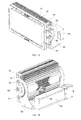
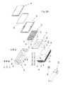
- an LED lighting apparatus capable of adjusting its angle mainly includes an LED module 10, a light conversion panel 20, a heat dissipation unit 30, a protective cover 40, a mounting frame 50, a hinge pin 60, a locking pin 70, a locking bracket 80, a waterproof packing 90, and other components.
- the LED module 10 includes LEDs 11, and a PCB 13 on which the LEDs 11 are mounted.
- Each LED 11 may preferably comprise a chip-type LED 11 that is thin to occupy a small installation space and emits light of high luminance.
- the LEDs 11 of the LED module 10 are divided into a plurality of LED arrays 11A, 11B and 11C, so that each LED array 11A, 11B, 11C is independently turned on or off without being affected by other LED arrays.
- the LED array 11A, 11B, 11C means a combination of a plurality of LEDs 11 that are electrically connected to each other in series or in parallel to be supplied with the same power and are not electrically connected to the remaining LED arrays 11A, 11B, 11C.
- a power supply PS that supplies power to turn the LED module 10 on supplies power to the respective LED arrays 11A, 11B and 11C, independently.
- the power supply PS can stably supply power to the remaining LED arrays 11A, 11B and 11C.
- the PCB 13 may be divided into several portions corresponding to the respective LED arrays 11A, 11B and 11C.
- the PCB 13 of the LED module 10 may comprise unit PCBs 13A, 13B and 13C that are divided into each other to correspond to the respective LED arrays 11A, 11B and 11C.
- the PCB 13 may comprise a single PCB, with cut grooves 15 provided to allow the PCB to be divided into portions corresponding to the respective LED arrays 11A, 11B and 11C.
- the light conversion panel 20 is disposed in front of the LED module 10, and converts light, emitted from the LEDs 11, into parallel beams, thus uniformly radiating light to the front without diffusion or concentration and thereby enhancing an illumination quality.
- the light conversion panel 20 surrounds the periphery of the LEDs 11 to allow the incidence of all of the light emitted from the LEDs 11 without loss.
- the light conversion panel 20 includes a collimated lens 21 that converts the incident light into parallel beams and then radiates them, a holder 25 that holds the collimated lens 21, and a mounting board 23 to which the holder 25 is mounted.
- the LED module 10 is mounted to the front of the heat dissipation unit 30 in such a way as to be in contact therewith, and serves to dissipate heat, generated in the LED module 10, to the exterior.
- the heat dissipation unit 30 is made of aluminum that is high in heat conductivity and superior in workability, so that the heat dissipation unit 30 is high in heat dissipation properties and may be produced by extrusion, thus ensuring high productivity.
- a bolt hole 31 and a through hole 32 On the front of the heat dissipation unit 30 are formed a bolt hole 31 and a through hole 32.
- a bolt is inserted into the bolt hole 31 to fasten the LED module 10 to the heat dissipation unit 30.
- a cable (not shown) for supplying power to the LED module 10 passes through the through hole 32.
- the heat dissipation wings 33 serve to rapidly dissipate heat transferred from the LED module 10 to the exterior.
- the guide block 39 guides the cable connected to the power supply PS to the front.
- a hinge hole 34 and a locking hole 35 On a side surface of the heat dissipation unit 30 are formed a hinge hole 34 and a locking hole 35.
- the hinge hole 34 is used to rotatably hinge the heat dissipation unit 30 to the locking bracket 80.
- the locking hole 35 is used to lock the heat dissipation unit 30 to the locking bracket 80.
- the protective cover 40 covers the front of the heat dissipation unit 30 to protect the LED module 10 and the light conversion panel 20 accommodated therein.
- a rear (inner) edge of the protective cover 40 is in contact with a front edge of the heat dissipation unit 30, with a packing groove 41 formed on a contact portion.
- the waterproof packing 90 is inserted and seated in the packing groove 41.
- the waterproof packing 41 is pressurized by the protective cover 40 and the heat dissipation unit 30 to seal a gap therebetween, thus preventing moisture from penetrating into the lighting apparatus.
- the mounting frame 50 surrounds an edge of the protective cover 40 and is fastened to the front edge of the heat dissipation unit 30 via a bolt (not shown).
- the mounting frame 50 fastened via the bolt tightens the protective cover 40 towards the heat dissipation unit 30, thus allowing the waterproof packing 90 to be pressurized and come into close contact with the protective cover 40 and the heat dissipation unit 30.
- the hinge pin 60 hingedly joins the protective cover 40 to the mounting frame 50, thus allowing the protective cover 40 and the heat dissipation unit 30 coupled thereto to be rotated. Further, the hinge pin 60 tightens or loosens the protective cover 40, thus causing a gear part 43 to engage with or disengage from a corresponding gear part 53.
- the gear part 43 engages with the corresponding gear part 53 the protective cover 40 is not rotated and is fixed at this angle.
- the gear part 43 disengages from the corresponding gear part 53 the protective cover 40 is rotated to be adjusted at a desired angle.
- the locking bracket 80 includes a horizontal part 85 that is secured to an exterior fixing structure, vertical part 87 that are vertically connected to both ends of the horizontal part 85 to allow an angle of the heat dissipation unit 30 to be adjusted, and a mounting part 89 on which the power supply PS for supplying power to the LED module 10 is mounted.
- a plurality of bolt insert holes 86 is formed in the horizontal part 85, so that fastening bolts for fastening the locking bracket 80 to the exterior fixing structure are inserted into the bolt insert holes 86.
- a hinge hole 81 is formed in the vertical part 87 in such a way as to correspond to the hinge hole 34 of the heat dissipation unit 30, with the hinge pin 60 inserted into the hinge hole 81.
- a guide hole 83 is formed in the vertical part 87 in such a way as to correspond to the locking hole 35 of the heat dissipation unit 30, so that the locking pin 70 is inserted into the guide hole 83, and thereby the guide hole 83 guides the movement of the locking pin 70.
- Heads of the hinge pin 60 and the locking pin 70 are disposed outside the locking bracket 80, and inner ends thereof are screwed into the hinge hole 34 and the locking hole 35 of the heat dissipation unit 30, respectively, thus tightening or loosening the heat dissipation unit 30 to or from the locking bracket 80.
- the heat dissipation unit 30 may rotate via the hinge pin 60.
- the locking pin 70 moves along the guide hole 83 during the rotation of the heat dissipation unit 30, thus guiding the rotation of the heat dissipation unit 30.
- the hinge pin 60 and the locking pin 70 tightening the heat dissipation unit 30 and the locking bracket 80, they are fastened to each other.
- the heat dissipation unit 30 and the locking bracket 80 are simultaneously tightened at two places, so that stronger and more stable tightening force is obtained.
- the hinge hole 81, the guide hole 83, the hinge hole 34, the locking hole 35, the hinge pin 60, and the locking pin 70 constitute the angle adjusting means.
- locking pins 70 are provided on opposite sides above and below the hinge pin 60, thus limiting an angle at which the heat dissipation unit 30 rotates forwards or rearwards.
- a user desires to further rotate the heat dissipation unit 30 forwards or rearwards beyond the limited angle, he or she only has to remove the locking pin 70 above or below the hinge pin 60.
- an additional locking hole 38 is formed in the heat dissipation unit 30, and the locking bracket 80 has an additional bolt insert hole 88 corresponding to the additional locking hole 38, thus allowing the additional fastening bolt (not shown) to be fastened to the additional locking hole 38 and the additional bolt insert hole 88.
Landscapes
- Engineering & Computer Science (AREA)
- General Engineering & Computer Science (AREA)
- Physics & Mathematics (AREA)
- Electromagnetism (AREA)
- Arrangement Of Elements, Cooling, Sealing, Or The Like Of Lighting Devices (AREA)
- Fastening Of Light Sources Or Lamp Holders (AREA)
Applications Claiming Priority (1)
| Application Number | Priority Date | Filing Date | Title |
|---|---|---|---|
| KR20120143198A KR101284156B1 (ko) | 2012-12-11 | 2012-12-11 | 독자적으로 점소등되는 led어레이들을 갖는 led 조명장치 |
Publications (3)
| Publication Number | Publication Date |
|---|---|
| EP2743576A2 true EP2743576A2 (de) | 2014-06-18 |
| EP2743576A3 EP2743576A3 (de) | 2015-04-15 |
| EP2743576B1 EP2743576B1 (de) | 2016-07-20 |
Family
ID=48996947
Family Applications (1)
| Application Number | Title | Priority Date | Filing Date |
|---|---|---|---|
| EP13196482.7A Active EP2743576B1 (de) | 2012-12-11 | 2013-12-10 | LED-Beleuchtungsvorrichtung mit unabhängig ein- oder ausschaltbaren LED-Gruppen |
Country Status (3)
| Country | Link |
|---|---|
| EP (1) | EP2743576B1 (de) |
| KR (1) | KR101284156B1 (de) |
| AU (1) | AU2013267063A1 (de) |
Cited By (4)
| Publication number | Priority date | Publication date | Assignee | Title |
|---|---|---|---|---|
| EP2902702A1 (de) * | 2014-01-31 | 2015-08-05 | Toshiba Lighting & Technology Corporation | Beleuchtungsvorrichtung |
| CN104832838A (zh) * | 2015-05-04 | 2015-08-12 | 广州市升龙灯光设备有限公司 | 隐藏式防水导风结构 |
| US20240065154A1 (en) * | 2022-08-30 | 2024-02-29 | Cnh Industrial America Llc | Hydraulic cooler pressure isolation circuit for a header of an agricultural harvester |
| EP4685394A1 (de) * | 2024-07-25 | 2026-01-28 | GEWISS S.p.A. | Beleuchtungsvorrichtung mit einer halterung und einer einstellvorrichtung des beleuchtungskörpers |
Families Citing this family (5)
| Publication number | Priority date | Publication date | Assignee | Title |
|---|---|---|---|---|
| KR101475143B1 (ko) * | 2013-04-25 | 2014-12-22 | 장경 | 방송용 led 조명 장치 |
| CN204005325U (zh) | 2014-05-27 | 2014-12-10 | 广州盛龙照明有限公司 | 一种多功能模组式灯 |
| CN104033868B (zh) * | 2014-06-05 | 2017-05-17 | 江苏泛亚微透科技股份有限公司 | 汽车车灯用透湿栓 |
| KR102193041B1 (ko) * | 2020-05-13 | 2020-12-18 | 김미애 | 각도조절수단이 지상에 구비된 가로등 |
| KR102243895B1 (ko) * | 2020-05-13 | 2021-04-23 | 김미애 | 각도조절 수단을 포함하는 가로등용 led 모듈 |
Citations (3)
| Publication number | Priority date | Publication date | Assignee | Title |
|---|---|---|---|---|
| KR100460370B1 (ko) | 2000-12-13 | 2004-12-08 | 아사히 가세이 가부시키가이샤 | 산화 또는 가암모니아 산화 반응용 산화물 촉매 |
| KR20090023959A (ko) | 2007-09-03 | 2009-03-06 | 임선택 | 진열용 조명장치 |
| KR101115550B1 (ko) | 2011-10-06 | 2012-03-05 | 김종천 | 야외용 led 조명장치 |
Family Cites Families (11)
| Publication number | Priority date | Publication date | Assignee | Title |
|---|---|---|---|---|
| GB0420632D0 (en) * | 2004-09-17 | 2004-10-20 | Lumidrives Ltd | Light emitting diode (LED) control |
| US7217006B2 (en) * | 2004-11-20 | 2007-05-15 | Automatic Power, Inc. | Variation of power levels within an LED array |
| KR100944521B1 (ko) * | 2007-10-29 | 2010-03-03 | 주식회사 웰라이트 | 가로등용 조명장치 |
| US7696698B2 (en) * | 2007-12-31 | 2010-04-13 | Lumination Llc | LEDs tricolor power signal |
| US7988346B2 (en) * | 2008-03-24 | 2011-08-02 | Ibis Tek, Llc | All-LED visible light and IR light headlamp |
| KR200460370Y1 (ko) * | 2009-01-08 | 2012-05-21 | 비전엑스아시아 주식회사 | 차량용 조명기구 고정구조 |
| US7936135B2 (en) * | 2009-07-17 | 2011-05-03 | Bridgelux, Inc | Reconfigurable LED array and use in lighting system |
| US8517566B2 (en) * | 2009-09-25 | 2013-08-27 | Musco Corporation | Apparatus, method, and system for roadway lighting using solid-state light sources |
| KR101123077B1 (ko) * | 2009-09-30 | 2012-03-16 | 주식회사 아모럭스 | 블록 조립 구조를 갖는 led 조명장치 |
| DK177579B1 (en) * | 2010-04-23 | 2013-10-28 | Martin Professional As | Led light fixture with background lighting |
| EP2614301A1 (de) * | 2010-09-10 | 2013-07-17 | Robe Lighting, Inc | Leiterplatte für eine led-leuchte |
-
2012
- 2012-12-11 KR KR20120143198A patent/KR101284156B1/ko active Active
-
2013
- 2013-12-06 AU AU2013267063A patent/AU2013267063A1/en not_active Abandoned
- 2013-12-10 EP EP13196482.7A patent/EP2743576B1/de active Active
Patent Citations (3)
| Publication number | Priority date | Publication date | Assignee | Title |
|---|---|---|---|---|
| KR100460370B1 (ko) | 2000-12-13 | 2004-12-08 | 아사히 가세이 가부시키가이샤 | 산화 또는 가암모니아 산화 반응용 산화물 촉매 |
| KR20090023959A (ko) | 2007-09-03 | 2009-03-06 | 임선택 | 진열용 조명장치 |
| KR101115550B1 (ko) | 2011-10-06 | 2012-03-05 | 김종천 | 야외용 led 조명장치 |
Cited By (4)
| Publication number | Priority date | Publication date | Assignee | Title |
|---|---|---|---|---|
| EP2902702A1 (de) * | 2014-01-31 | 2015-08-05 | Toshiba Lighting & Technology Corporation | Beleuchtungsvorrichtung |
| CN104832838A (zh) * | 2015-05-04 | 2015-08-12 | 广州市升龙灯光设备有限公司 | 隐藏式防水导风结构 |
| US20240065154A1 (en) * | 2022-08-30 | 2024-02-29 | Cnh Industrial America Llc | Hydraulic cooler pressure isolation circuit for a header of an agricultural harvester |
| EP4685394A1 (de) * | 2024-07-25 | 2026-01-28 | GEWISS S.p.A. | Beleuchtungsvorrichtung mit einer halterung und einer einstellvorrichtung des beleuchtungskörpers |
Also Published As
| Publication number | Publication date |
|---|---|
| AU2013267063A1 (en) | 2014-06-26 |
| KR101284156B1 (ko) | 2013-07-10 |
| EP2743576B1 (de) | 2016-07-20 |
| EP2743576A3 (de) | 2015-04-15 |
Similar Documents
| Publication | Publication Date | Title |
|---|---|---|
| EP2743576B1 (de) | LED-Beleuchtungsvorrichtung mit unabhängig ein- oder ausschaltbaren LED-Gruppen | |
| EP3076073B1 (de) | Verbesserungen für oder verbauden mit modularen leuchtvorrichtungen | |
| US11935440B2 (en) | Display apparatus and hinge assembly of display module | |
| US20100254148A1 (en) | Lamp holder structure having heat dissipation fins | |
| KR101017118B1 (ko) | 엘이디 조명기구 | |
| US7637638B2 (en) | Lighting apparatus | |
| US9470407B2 (en) | Airfield lighting apparatus | |
| US9506631B2 (en) | Profile rail, connecting element, illuminating module, lighting system and light box | |
| US20100172132A1 (en) | Structure of overhead lamp and mounting bracket for constructional vehicle | |
| JP5704703B2 (ja) | トンネル用照明装置 | |
| US20140321054A1 (en) | Carrier for a display module and display apparatus having such a carrier | |
| KR101276786B1 (ko) | 각도조절이 가능한 led 조명장치 | |
| EP3055610B1 (de) | Beleuchtungsvorrichtung mit hochleistungs-led | |
| US20140313778A1 (en) | Multi-Wing Edge-Lit Structure | |
| US9494301B2 (en) | Lighting housing having self-adjusting hinge mechanism | |
| AU2015100673A4 (en) | Led lighting apparatus having led arrays turned on or off independently | |
| US20210239305A1 (en) | Adjustable, modular flood light fixture | |
| US20120293994A1 (en) | LED Lighting Fixture | |
| US11081027B2 (en) | Front-illuminated sign | |
| JP6241726B2 (ja) | 光源モジュール及び照明装置 | |
| US20160170134A1 (en) | Backlight Module and Liquid Crystal Display | |
| CN210462873U (zh) | 车灯镜头组件及车灯模块 | |
| CN212901066U (zh) | 一种可单独调角度的模组式路灯 | |
| JP6355038B2 (ja) | 光源モジュール及び照明装置 | |
| US9341347B2 (en) | Method for mounting lighting modules and equipment therefor |
Legal Events
| Date | Code | Title | Description |
|---|---|---|---|
| PUAI | Public reference made under article 153(3) epc to a published international application that has entered the european phase |
Free format text: ORIGINAL CODE: 0009012 |
|
| 17P | Request for examination filed |
Effective date: 20131210 |
|
| AK | Designated contracting states |
Kind code of ref document: A2 Designated state(s): AL AT BE BG CH CY CZ DE DK EE ES FI FR GB GR HR HU IE IS IT LI LT LU LV MC MK MT NL NO PL PT RO RS SE SI SK SM TR |
|
| AX | Request for extension of the european patent |
Extension state: BA ME |
|
| PUAL | Search report despatched |
Free format text: ORIGINAL CODE: 0009013 |
|
| AK | Designated contracting states |
Kind code of ref document: A3 Designated state(s): AL AT BE BG CH CY CZ DE DK EE ES FI FR GB GR HR HU IE IS IT LI LT LU LV MC MK MT NL NO PL PT RO RS SE SI SK SM TR |
|
| AX | Request for extension of the european patent |
Extension state: BA ME |
|
| RIC1 | Information provided on ipc code assigned before grant |
Ipc: F21Y 101/02 20060101ALN20150306BHEP Ipc: F21V 31/00 20060101ALN20150306BHEP Ipc: H05B 33/08 20060101ALI20150306BHEP Ipc: F21V 29/00 20150101AFI20150306BHEP Ipc: F21W 131/40 20060101ALN20150306BHEP Ipc: F21W 131/10 20060101ALN20150306BHEP Ipc: F21Y 105/00 20060101ALN20150306BHEP Ipc: F21V 21/30 20060101ALN20150306BHEP |
|
| R17P | Request for examination filed (corrected) |
Effective date: 20151007 |
|
| RBV | Designated contracting states (corrected) |
Designated state(s): AL AT BE BG CH CY CZ DE DK EE ES FI FR GB GR HR HU IE IS IT LI LT LU LV MC MK MT NL NO PL PT RO RS SE SI SK SM TR |
|
| REG | Reference to a national code |
Ref country code: DE Ref legal event code: R079 Ref document number: 602013009546 Country of ref document: DE Free format text: PREVIOUS MAIN CLASS: F21V0029000000 Ipc: F21V0029760000 |
|
| GRAP | Despatch of communication of intention to grant a patent |
Free format text: ORIGINAL CODE: EPIDOSNIGR1 |
|
| RIC1 | Information provided on ipc code assigned before grant |
Ipc: F21Y 105/10 20160101ALN20160128BHEP Ipc: F21V 29/76 20150101AFI20160128BHEP Ipc: F21W 131/40 20060101ALN20160128BHEP Ipc: F21W 131/10 20060101ALN20160128BHEP Ipc: H05B 33/08 20060101ALI20160128BHEP Ipc: F21V 21/30 20060101ALI20160128BHEP Ipc: F21V 31/00 20060101ALN20160128BHEP Ipc: F21Y 115/10 20160101ALN20160128BHEP |
|
| INTG | Intention to grant announced |
Effective date: 20160224 |
|
| GRAS | Grant fee paid |
Free format text: ORIGINAL CODE: EPIDOSNIGR3 |
|
| GRAA | (expected) grant |
Free format text: ORIGINAL CODE: 0009210 |
|
| AK | Designated contracting states |
Kind code of ref document: B1 Designated state(s): AL AT BE BG CH CY CZ DE DK EE ES FI FR GB GR HR HU IE IS IT LI LT LU LV MC MK MT NL NO PL PT RO RS SE SI SK SM TR |
|
| REG | Reference to a national code |
Ref country code: GB Ref legal event code: FG4D |
|
| REG | Reference to a national code |
Ref country code: CH Ref legal event code: EP |
|
| REG | Reference to a national code |
Ref country code: IE Ref legal event code: FG4D |
|
| REG | Reference to a national code |
Ref country code: AT Ref legal event code: REF Ref document number: 814421 Country of ref document: AT Kind code of ref document: T Effective date: 20160815 |
|
| REG | Reference to a national code |
Ref country code: NL Ref legal event code: FP |
|
| REG | Reference to a national code |
Ref country code: DE Ref legal event code: R096 Ref document number: 602013009546 Country of ref document: DE |
|
| REG | Reference to a national code |
Ref country code: NO Ref legal event code: T2 Effective date: 20160720 |
|
| REG | Reference to a national code |
Ref country code: SE Ref legal event code: TRGR |
|
| REG | Reference to a national code |
Ref country code: LT Ref legal event code: MG4D |
|
| REG | Reference to a national code |
Ref country code: FR Ref legal event code: PLFP Year of fee payment: 4 |
|
| REG | Reference to a national code |
Ref country code: AT Ref legal event code: MK05 Ref document number: 814421 Country of ref document: AT Kind code of ref document: T Effective date: 20160720 |
|
| PG25 | Lapsed in a contracting state [announced via postgrant information from national office to epo] |
Ref country code: LT Free format text: LAPSE BECAUSE OF FAILURE TO SUBMIT A TRANSLATION OF THE DESCRIPTION OR TO PAY THE FEE WITHIN THE PRESCRIBED TIME-LIMIT Effective date: 20160720 Ref country code: IS Free format text: LAPSE BECAUSE OF FAILURE TO SUBMIT A TRANSLATION OF THE DESCRIPTION OR TO PAY THE FEE WITHIN THE PRESCRIBED TIME-LIMIT Effective date: 20161120 Ref country code: RS Free format text: LAPSE BECAUSE OF FAILURE TO SUBMIT A TRANSLATION OF THE DESCRIPTION OR TO PAY THE FEE WITHIN THE PRESCRIBED TIME-LIMIT Effective date: 20160720 Ref country code: HR Free format text: LAPSE BECAUSE OF FAILURE TO SUBMIT A TRANSLATION OF THE DESCRIPTION OR TO PAY THE FEE WITHIN THE PRESCRIBED TIME-LIMIT Effective date: 20160720 |
|
| PG25 | Lapsed in a contracting state [announced via postgrant information from national office to epo] |
Ref country code: LV Free format text: LAPSE BECAUSE OF FAILURE TO SUBMIT A TRANSLATION OF THE DESCRIPTION OR TO PAY THE FEE WITHIN THE PRESCRIBED TIME-LIMIT Effective date: 20160720 Ref country code: ES Free format text: LAPSE BECAUSE OF FAILURE TO SUBMIT A TRANSLATION OF THE DESCRIPTION OR TO PAY THE FEE WITHIN THE PRESCRIBED TIME-LIMIT Effective date: 20160720 Ref country code: PL Free format text: LAPSE BECAUSE OF FAILURE TO SUBMIT A TRANSLATION OF THE DESCRIPTION OR TO PAY THE FEE WITHIN THE PRESCRIBED TIME-LIMIT Effective date: 20160720 Ref country code: AT Free format text: LAPSE BECAUSE OF FAILURE TO SUBMIT A TRANSLATION OF THE DESCRIPTION OR TO PAY THE FEE WITHIN THE PRESCRIBED TIME-LIMIT Effective date: 20160720 Ref country code: GR Free format text: LAPSE BECAUSE OF FAILURE TO SUBMIT A TRANSLATION OF THE DESCRIPTION OR TO PAY THE FEE WITHIN THE PRESCRIBED TIME-LIMIT Effective date: 20161021 Ref country code: PT Free format text: LAPSE BECAUSE OF FAILURE TO SUBMIT A TRANSLATION OF THE DESCRIPTION OR TO PAY THE FEE WITHIN THE PRESCRIBED TIME-LIMIT Effective date: 20161121 |
|
| REG | Reference to a national code |
Ref country code: DE Ref legal event code: R097 Ref document number: 602013009546 Country of ref document: DE |
|
| PG25 | Lapsed in a contracting state [announced via postgrant information from national office to epo] |
Ref country code: EE Free format text: LAPSE BECAUSE OF FAILURE TO SUBMIT A TRANSLATION OF THE DESCRIPTION OR TO PAY THE FEE WITHIN THE PRESCRIBED TIME-LIMIT Effective date: 20160720 Ref country code: RO Free format text: LAPSE BECAUSE OF FAILURE TO SUBMIT A TRANSLATION OF THE DESCRIPTION OR TO PAY THE FEE WITHIN THE PRESCRIBED TIME-LIMIT Effective date: 20160720 |
|
| PLBE | No opposition filed within time limit |
Free format text: ORIGINAL CODE: 0009261 |
|
| STAA | Information on the status of an ep patent application or granted ep patent |
Free format text: STATUS: NO OPPOSITION FILED WITHIN TIME LIMIT |
|
| PG25 | Lapsed in a contracting state [announced via postgrant information from national office to epo] |
Ref country code: BG Free format text: LAPSE BECAUSE OF FAILURE TO SUBMIT A TRANSLATION OF THE DESCRIPTION OR TO PAY THE FEE WITHIN THE PRESCRIBED TIME-LIMIT Effective date: 20161020 Ref country code: SM Free format text: LAPSE BECAUSE OF FAILURE TO SUBMIT A TRANSLATION OF THE DESCRIPTION OR TO PAY THE FEE WITHIN THE PRESCRIBED TIME-LIMIT Effective date: 20160720 Ref country code: SK Free format text: LAPSE BECAUSE OF FAILURE TO SUBMIT A TRANSLATION OF THE DESCRIPTION OR TO PAY THE FEE WITHIN THE PRESCRIBED TIME-LIMIT Effective date: 20160720 Ref country code: CZ Free format text: LAPSE BECAUSE OF FAILURE TO SUBMIT A TRANSLATION OF THE DESCRIPTION OR TO PAY THE FEE WITHIN THE PRESCRIBED TIME-LIMIT Effective date: 20160720 Ref country code: DK Free format text: LAPSE BECAUSE OF FAILURE TO SUBMIT A TRANSLATION OF THE DESCRIPTION OR TO PAY THE FEE WITHIN THE PRESCRIBED TIME-LIMIT Effective date: 20160720 |
|
| 26N | No opposition filed |
Effective date: 20170421 |
|
| REG | Reference to a national code |
Ref country code: CH Ref legal event code: PL |
|
| PG25 | Lapsed in a contracting state [announced via postgrant information from national office to epo] |
Ref country code: SI Free format text: LAPSE BECAUSE OF FAILURE TO SUBMIT A TRANSLATION OF THE DESCRIPTION OR TO PAY THE FEE WITHIN THE PRESCRIBED TIME-LIMIT Effective date: 20160720 |
|
| PG25 | Lapsed in a contracting state [announced via postgrant information from national office to epo] |
Ref country code: MC Free format text: LAPSE BECAUSE OF FAILURE TO SUBMIT A TRANSLATION OF THE DESCRIPTION OR TO PAY THE FEE WITHIN THE PRESCRIBED TIME-LIMIT Effective date: 20160720 |
|
| REG | Reference to a national code |
Ref country code: IE Ref legal event code: MM4A |
|
| PG25 | Lapsed in a contracting state [announced via postgrant information from national office to epo] |
Ref country code: LU Free format text: LAPSE BECAUSE OF NON-PAYMENT OF DUE FEES Effective date: 20161210 Ref country code: LI Free format text: LAPSE BECAUSE OF NON-PAYMENT OF DUE FEES Effective date: 20161231 Ref country code: CH Free format text: LAPSE BECAUSE OF NON-PAYMENT OF DUE FEES Effective date: 20161231 |
|
| REG | Reference to a national code |
Ref country code: FR Ref legal event code: PLFP Year of fee payment: 5 |
|
| PG25 | Lapsed in a contracting state [announced via postgrant information from national office to epo] |
Ref country code: IE Free format text: LAPSE BECAUSE OF NON-PAYMENT OF DUE FEES Effective date: 20161210 |
|
| PG25 | Lapsed in a contracting state [announced via postgrant information from national office to epo] |
Ref country code: HU Free format text: LAPSE BECAUSE OF FAILURE TO SUBMIT A TRANSLATION OF THE DESCRIPTION OR TO PAY THE FEE WITHIN THE PRESCRIBED TIME-LIMIT; INVALID AB INITIO Effective date: 20131210 |
|
| PG25 | Lapsed in a contracting state [announced via postgrant information from national office to epo] |
Ref country code: MK Free format text: LAPSE BECAUSE OF FAILURE TO SUBMIT A TRANSLATION OF THE DESCRIPTION OR TO PAY THE FEE WITHIN THE PRESCRIBED TIME-LIMIT Effective date: 20160720 Ref country code: CY Free format text: LAPSE BECAUSE OF FAILURE TO SUBMIT A TRANSLATION OF THE DESCRIPTION OR TO PAY THE FEE WITHIN THE PRESCRIBED TIME-LIMIT Effective date: 20160720 |
|
| PG25 | Lapsed in a contracting state [announced via postgrant information from national office to epo] |
Ref country code: MT Free format text: LAPSE BECAUSE OF NON-PAYMENT OF DUE FEES Effective date: 20161210 |
|
| PG25 | Lapsed in a contracting state [announced via postgrant information from national office to epo] |
Ref country code: TR Free format text: LAPSE BECAUSE OF FAILURE TO SUBMIT A TRANSLATION OF THE DESCRIPTION OR TO PAY THE FEE WITHIN THE PRESCRIBED TIME-LIMIT Effective date: 20160720 Ref country code: AL Free format text: LAPSE BECAUSE OF FAILURE TO SUBMIT A TRANSLATION OF THE DESCRIPTION OR TO PAY THE FEE WITHIN THE PRESCRIBED TIME-LIMIT Effective date: 20160720 |
|
| PGFP | Annual fee paid to national office [announced via postgrant information from national office to epo] |
Ref country code: FI Payment date: 20191209 Year of fee payment: 7 Ref country code: NO Payment date: 20191210 Year of fee payment: 7 Ref country code: NL Payment date: 20191212 Year of fee payment: 7 |
|
| PGFP | Annual fee paid to national office [announced via postgrant information from national office to epo] |
Ref country code: FR Payment date: 20191115 Year of fee payment: 7 |
|
| PGFP | Annual fee paid to national office [announced via postgrant information from national office to epo] |
Ref country code: GB Payment date: 20191206 Year of fee payment: 7 |
|
| REG | Reference to a national code |
Ref country code: FI Ref legal event code: MAE |
|
| REG | Reference to a national code |
Ref country code: NO Ref legal event code: MMEP |
|
| PG25 | Lapsed in a contracting state [announced via postgrant information from national office to epo] |
Ref country code: FI Free format text: LAPSE BECAUSE OF NON-PAYMENT OF DUE FEES Effective date: 20201210 |
|
| REG | Reference to a national code |
Ref country code: NL Ref legal event code: MM Effective date: 20210101 |
|
| GBPC | Gb: european patent ceased through non-payment of renewal fee |
Effective date: 20201210 |
|
| PG25 | Lapsed in a contracting state [announced via postgrant information from national office to epo] |
Ref country code: NL Free format text: LAPSE BECAUSE OF NON-PAYMENT OF DUE FEES Effective date: 20210101 |
|
| REG | Reference to a national code |
Ref country code: DE Ref legal event code: R081 Ref document number: 602013009546 Country of ref document: DE Owner name: BROWN & WATSON INTERNATIONAL LIMITED, HWASEONG, KR Free format text: FORMER OWNERS: KO, IN-HONG, SEOUL, KR; VISION X ASIA CO., LTD., INCHEON-SI, KR Ref country code: DE Ref legal event code: R081 Ref document number: 602013009546 Country of ref document: DE Owner name: VISION X ASIA CO., LTD., HWASEONG-SI, KR Free format text: FORMER OWNERS: KO, IN-HONG, SEOUL, KR; VISION X ASIA CO., LTD., INCHEON-SI, KR |
|
| PG25 | Lapsed in a contracting state [announced via postgrant information from national office to epo] |
Ref country code: FR Free format text: LAPSE BECAUSE OF NON-PAYMENT OF DUE FEES Effective date: 20201231 |
|
| REG | Reference to a national code |
Ref country code: BE Ref legal event code: PD Owner name: VISION X ASIA CO., LTD.; KR Free format text: DETAILS ASSIGNMENT: CHANGE OF OWNER(S), ASSIGNMENT; FORMER OWNER NAME: KO, IN-HONG Effective date: 20211015 |
|
| PG25 | Lapsed in a contracting state [announced via postgrant information from national office to epo] |
Ref country code: NO Free format text: LAPSE BECAUSE OF NON-PAYMENT OF DUE FEES Effective date: 20201231 Ref country code: GB Free format text: LAPSE BECAUSE OF NON-PAYMENT OF DUE FEES Effective date: 20201210 |
|
| REG | Reference to a national code |
Ref country code: DE Ref legal event code: R082 Country of ref document: DE Ref country code: DE Ref legal event code: R082 Ref document number: 602013009546 Country of ref document: DE Representative=s name: MANITZ FINSTERWALD PATENT- UND RECHTSANWALTSPA, DE |
|
| REG | Reference to a national code |
Ref country code: DE Ref legal event code: R081 Ref document number: 602013009546 Country of ref document: DE Owner name: BROWN & WATSON INTERNATIONAL LIMITED, HWASEONG, KR Free format text: FORMER OWNER: VISION X ASIA CO., LTD., HWASEONG-SI, GYEONGGI-DO, KR Ref country code: DE Ref legal event code: R082 Ref document number: 602013009546 Country of ref document: DE Representative=s name: MANITZ FINSTERWALD PATENT- UND RECHTSANWALTSPA, DE |
|
| REG | Reference to a national code |
Ref country code: BE Ref legal event code: PD Owner name: BROWN & WATSON INTERNATIONAL LIMITED; KR Free format text: DETAILS ASSIGNMENT: CHANGE OF OWNER(S), ASSIGNMENT; FORMER OWNER NAME: KO, IN-HONG Effective date: 20211202 |
|
| PGFP | Annual fee paid to national office [announced via postgrant information from national office to epo] |
Ref country code: DE Payment date: 20250930 Year of fee payment: 13 |
|
| PGFP | Annual fee paid to national office [announced via postgrant information from national office to epo] |
Ref country code: IT Payment date: 20251121 Year of fee payment: 13 |
|
| PGFP | Annual fee paid to national office [announced via postgrant information from national office to epo] |
Ref country code: BE Payment date: 20251003 Year of fee payment: 13 |
|
| PGFP | Annual fee paid to national office [announced via postgrant information from national office to epo] |
Ref country code: SE Payment date: 20251001 Year of fee payment: 13 |