EP2743368A1 - Metal strip stabilizer, method for manufacturing hot dipped metal strip, and metal strip - Google Patents
Metal strip stabilizer, method for manufacturing hot dipped metal strip, and metal strip Download PDFInfo
- Publication number
- EP2743368A1 EP2743368A1 EP12821917.7A EP12821917A EP2743368A1 EP 2743368 A1 EP2743368 A1 EP 2743368A1 EP 12821917 A EP12821917 A EP 12821917A EP 2743368 A1 EP2743368 A1 EP 2743368A1
- Authority
- EP
- European Patent Office
- Prior art keywords
- coil
- metal strip
- position correction
- vibration suppression
- signal
- Prior art date
- Legal status (The legal status is an assumption and is not a legal conclusion. Google has not performed a legal analysis and makes no representation as to the accuracy of the status listed.)
- Granted
Links
Images


Classifications
-
- B—PERFORMING OPERATIONS; TRANSPORTING
- B65—CONVEYING; PACKING; STORING; HANDLING THIN OR FILAMENTARY MATERIAL
- B65H—HANDLING THIN OR FILAMENTARY MATERIAL, e.g. SHEETS, WEBS, CABLES
- B65H23/00—Registering, tensioning, smoothing or guiding webs
-
- C—CHEMISTRY; METALLURGY
- C23—COATING METALLIC MATERIAL; COATING MATERIAL WITH METALLIC MATERIAL; CHEMICAL SURFACE TREATMENT; DIFFUSION TREATMENT OF METALLIC MATERIAL; COATING BY VACUUM EVAPORATION, BY SPUTTERING, BY ION IMPLANTATION OR BY CHEMICAL VAPOUR DEPOSITION, IN GENERAL; INHIBITING CORROSION OF METALLIC MATERIAL OR INCRUSTATION IN GENERAL
- C23C—COATING METALLIC MATERIAL; COATING MATERIAL WITH METALLIC MATERIAL; SURFACE TREATMENT OF METALLIC MATERIAL BY DIFFUSION INTO THE SURFACE, BY CHEMICAL CONVERSION OR SUBSTITUTION; COATING BY VACUUM EVAPORATION, BY SPUTTERING, BY ION IMPLANTATION OR BY CHEMICAL VAPOUR DEPOSITION, IN GENERAL
- C23C2/00—Hot-dipping or immersion processes for applying the coating material in the molten state without affecting the shape; Apparatus therefor
- C23C2/003—Apparatus
- C23C2/0034—Details related to elements immersed in bath
- C23C2/00342—Moving elements, e.g. pumps or mixers
- C23C2/00344—Means for moving substrates, e.g. immersed rollers or immersed bearings
-
- C—CHEMISTRY; METALLURGY
- C23—COATING METALLIC MATERIAL; COATING MATERIAL WITH METALLIC MATERIAL; CHEMICAL SURFACE TREATMENT; DIFFUSION TREATMENT OF METALLIC MATERIAL; COATING BY VACUUM EVAPORATION, BY SPUTTERING, BY ION IMPLANTATION OR BY CHEMICAL VAPOUR DEPOSITION, IN GENERAL; INHIBITING CORROSION OF METALLIC MATERIAL OR INCRUSTATION IN GENERAL
- C23C—COATING METALLIC MATERIAL; COATING MATERIAL WITH METALLIC MATERIAL; SURFACE TREATMENT OF METALLIC MATERIAL BY DIFFUSION INTO THE SURFACE, BY CHEMICAL CONVERSION OR SUBSTITUTION; COATING BY VACUUM EVAPORATION, BY SPUTTERING, BY ION IMPLANTATION OR BY CHEMICAL VAPOUR DEPOSITION, IN GENERAL
- C23C2/00—Hot-dipping or immersion processes for applying the coating material in the molten state without affecting the shape; Apparatus therefor
- C23C2/003—Apparatus
- C23C2/0038—Apparatus characterised by the pre-treatment chambers located immediately upstream of the bath or occurring locally before the dipping process
-
- C—CHEMISTRY; METALLURGY
- C23—COATING METALLIC MATERIAL; COATING MATERIAL WITH METALLIC MATERIAL; CHEMICAL SURFACE TREATMENT; DIFFUSION TREATMENT OF METALLIC MATERIAL; COATING BY VACUUM EVAPORATION, BY SPUTTERING, BY ION IMPLANTATION OR BY CHEMICAL VAPOUR DEPOSITION, IN GENERAL; INHIBITING CORROSION OF METALLIC MATERIAL OR INCRUSTATION IN GENERAL
- C23C—COATING METALLIC MATERIAL; COATING MATERIAL WITH METALLIC MATERIAL; SURFACE TREATMENT OF METALLIC MATERIAL BY DIFFUSION INTO THE SURFACE, BY CHEMICAL CONVERSION OR SUBSTITUTION; COATING BY VACUUM EVAPORATION, BY SPUTTERING, BY ION IMPLANTATION OR BY CHEMICAL VAPOUR DEPOSITION, IN GENERAL
- C23C2/00—Hot-dipping or immersion processes for applying the coating material in the molten state without affecting the shape; Apparatus therefor
- C23C2/34—Hot-dipping or immersion processes for applying the coating material in the molten state without affecting the shape; Apparatus therefor characterised by the shape of the material to be treated
- C23C2/36—Elongated material
- C23C2/40—Plates; Strips
-
- C—CHEMISTRY; METALLURGY
- C23—COATING METALLIC MATERIAL; COATING MATERIAL WITH METALLIC MATERIAL; CHEMICAL SURFACE TREATMENT; DIFFUSION TREATMENT OF METALLIC MATERIAL; COATING BY VACUUM EVAPORATION, BY SPUTTERING, BY ION IMPLANTATION OR BY CHEMICAL VAPOUR DEPOSITION, IN GENERAL; INHIBITING CORROSION OF METALLIC MATERIAL OR INCRUSTATION IN GENERAL
- C23C—COATING METALLIC MATERIAL; COATING MATERIAL WITH METALLIC MATERIAL; SURFACE TREATMENT OF METALLIC MATERIAL BY DIFFUSION INTO THE SURFACE, BY CHEMICAL CONVERSION OR SUBSTITUTION; COATING BY VACUUM EVAPORATION, BY SPUTTERING, BY ION IMPLANTATION OR BY CHEMICAL VAPOUR DEPOSITION, IN GENERAL
- C23C2/00—Hot-dipping or immersion processes for applying the coating material in the molten state without affecting the shape; Apparatus therefor
- C23C2/50—Controlling or regulating the coating processes
- C23C2/51—Computer-controlled implementation
-
- C—CHEMISTRY; METALLURGY
- C23—COATING METALLIC MATERIAL; COATING MATERIAL WITH METALLIC MATERIAL; CHEMICAL SURFACE TREATMENT; DIFFUSION TREATMENT OF METALLIC MATERIAL; COATING BY VACUUM EVAPORATION, BY SPUTTERING, BY ION IMPLANTATION OR BY CHEMICAL VAPOUR DEPOSITION, IN GENERAL; INHIBITING CORROSION OF METALLIC MATERIAL OR INCRUSTATION IN GENERAL
- C23C—COATING METALLIC MATERIAL; COATING MATERIAL WITH METALLIC MATERIAL; SURFACE TREATMENT OF METALLIC MATERIAL BY DIFFUSION INTO THE SURFACE, BY CHEMICAL CONVERSION OR SUBSTITUTION; COATING BY VACUUM EVAPORATION, BY SPUTTERING, BY ION IMPLANTATION OR BY CHEMICAL VAPOUR DEPOSITION, IN GENERAL
- C23C2/00—Hot-dipping or immersion processes for applying the coating material in the molten state without affecting the shape; Apparatus therefor
- C23C2/50—Controlling or regulating the coating processes
- C23C2/52—Controlling or regulating the coating processes with means for measuring or sensing
- C23C2/524—Position of the substrate
- C23C2/5245—Position of the substrate for reducing vibrations of the substrate
-
- B—PERFORMING OPERATIONS; TRANSPORTING
- B65—CONVEYING; PACKING; STORING; HANDLING THIN OR FILAMENTARY MATERIAL
- B65H—HANDLING THIN OR FILAMENTARY MATERIAL, e.g. SHEETS, WEBS, CABLES
- B65H2557/00—Means for control not provided for in groups B65H2551/00 - B65H2555/00
- B65H2557/20—Calculating means; Controlling methods
- B65H2557/264—Calculating means; Controlling methods with key characteristics based on closed loop control
- B65H2557/2644—Calculating means; Controlling methods with key characteristics based on closed loop control characterised by PID control
-
- B—PERFORMING OPERATIONS; TRANSPORTING
- B65—CONVEYING; PACKING; STORING; HANDLING THIN OR FILAMENTARY MATERIAL
- B65H—HANDLING THIN OR FILAMENTARY MATERIAL, e.g. SHEETS, WEBS, CABLES
- B65H2557/00—Means for control not provided for in groups B65H2551/00 - B65H2555/00
- B65H2557/50—Use of particular electromagnetic waves, e.g. light, radiowaves or microwaves
-
- B—PERFORMING OPERATIONS; TRANSPORTING
- B65—CONVEYING; PACKING; STORING; HANDLING THIN OR FILAMENTARY MATERIAL
- B65H—HANDLING THIN OR FILAMENTARY MATERIAL, e.g. SHEETS, WEBS, CABLES
- B65H2601/00—Problem to be solved or advantage achieved
- B65H2601/50—Diminishing, minimizing or reducing
- B65H2601/52—Diminishing, minimizing or reducing entities relating to handling machine
- B65H2601/524—Vibration
-
- B—PERFORMING OPERATIONS; TRANSPORTING
- B65—CONVEYING; PACKING; STORING; HANDLING THIN OR FILAMENTARY MATERIAL
- B65H—HANDLING THIN OR FILAMENTARY MATERIAL, e.g. SHEETS, WEBS, CABLES
- B65H2701/00—Handled material; Storage means
- B65H2701/10—Handled articles or webs
- B65H2701/17—Nature of material
- B65H2701/173—Metal
Definitions
- the present invention relates to a metal strip stabilizer, a method of manufacturing a hot-dip coated metal strip using that, and a metal strip manufactured by using that.
- suppressing vibration or warp of a metal strip to maintain a stable metal strip pass line contributes to improve not only quality of the metal strip but also efficiency of the manufacturing line.
- a process of adhering molten metal to a surface of a metal strip by passing and immersing the metal strip through a hot-dip metal bath there is a process of adhering molten metal to a surface of a metal strip by passing and immersing the metal strip through a hot-dip metal bath.
- an adjustment is performed to shake off the molten metal excessively adhering to the metal strip by discharging wiping gas from a gas wiper provided subsequent to the hot-dip metal bath.
- a technique that stabilizes the metal strip pass line by suppressing the warp or the vibration of a metal strip in a non-contact manner by using an electromagnet.
- a method is known that disposes a pair of electromagnets to face each other with respect to a pass line moving a metal strip and makes attraction forces of the electromagnets, while being switched alternatively in accordance with a signal from a position detector disposed separately, act on the metal strip (see Patent Document 1).
- the above-described metal strip vibration control using the electromagnets requires responsiveness of the electromagnets, and the warp correction and the pass line correction require the attraction forces of the electromagnets.
- a combination of warp correction and pass line correction is hereinafter called the position correction. That is, in order to realize suppressing of vibration and correction of position of a metal strip simultaneously, mutually contradictory characteristics of responsiveness and attraction force are necessary. That is because responsiveness of the electromagnet becomes worsened if the winding number of a coil is increased to increase attraction force of the electromagnet, and on the other hand, attraction force of the electromagnet decreases if the winding number is decreased to improve responsiveness of the electromagnet.
- the metal strip stabilizer using the electromagnets having two independent systems of coils one for suppressing vibration and the other for correcting position, can perform the control with establishing both vibration-control performance and position correction performance, there was a problem that a mutual induction between the vibration suppression coil and the position correction coil decreased the vibration suppression performance.
- the present invention has been made in view of the above-mentioned circumstances and an object thereof is to provide a metal strip stabilizer which is capable of avoiding lowering of vibration suppression performance caused by an induced current between a vibration suppression coil and a position correction coil and a method of manufacturing a hot-dip coated metal strip using that.
- a metal strip stabilizer includes: a non-contact displacement sensor that measures displacement of a metal strip during online running; a control unit that outputs a vibration suppression signal for suppressing vibration of the metal strip and a position correction signal for correcting a position of the metal strip after a signal is input from the non-contact displacement sensor; a first coil that generates a magnetic force in accordance with the vibration suppression signal output from the control unit; a second coil that generates a magnetic force in accordance with the position correction signal output from the control unit, a winding number of the second coil being larger than a winding number of the first coil; a core around which the first coil and the second coil are wound concentrically and that induces the magnetic force generated by the first coil and the second coil to the metal strip; and a third coil that is disposed in series to an electric circuit supplying electricity to the second coil.
- the metal strip stabilizer of the present invention and the method of manufacturing a hot-dip coated metal strip, it is possible to avoid lowering of the vibration suppression performance caused by an induced current between the vibration suppression coil and the position correction coil.
- FIG. 1 is a schematic view showing a configuration of a metal strip stabilizer 1 according to the embodiment of the present invention.
- the stabilizer 1 according to the embodiment of the present invention includes a pair of electromagnets 3a and 3b disposed to face each other and to put therebetween a metal strip 2 running in a direction of an arrow A in the drawing, a non-contact displacement sensor 4 disposed in the vicinity of the electromagnets 3a and 3b, and a control unit 5 controlling the electromagnets 3a and 3b based on input from the non-contact displacement sensor 4.
- FIG. 2 is a schematic view showing an example of the electromagnet 3a used in the metal strip stabilizer 1 according to the embodiment of the present invention. It should be noted that herein only the electromagnet 3a for use of an obverse surface of the metal strip 2 will be explained, the following explanation is effective for the electromagnet 3b for use of a reverse surface of the metal strip 2.
- the electromagnet 3a shown in FIG. 2 is configured as a concentric coil consisting of a coil 7a and a coil 7b constituted by winding two coils concentrically around a core 6. Two coils 7a and 7b are configured by changing their winding numbers, one of the coils 7a and 7b having a smaller winding number is the vibration suppression coil 7a and the other one having a larger winding number is the position correction coil 7b.
- the vibration suppression coil 7a Although high responsiveness is required for the vibration suppression coil 7a in order to be capable of fully following a vibration frequency (usually, a natural vibration frequency of bending or warp of a metal strip) of the target metal strip 2, but, for suppressing vibration at a natural frequency of a metal strip, a large attraction force is not required. Therefore, the winding number of the vibration suppression coil 7a is configured to be smaller than that of the position correction coil 7b.
- the winding number of the position correction coil 7b is large within a range in which a size and a value of electric resistance of the electromagnet 3a are not too large.
- e Ldi / dt + Ri
- e an applied voltage
- i an electric current flowing in the coil
- L indicates an inductance of the coil
- R indicates resistance of the coil
- the attraction force F of the electromagnet is in proportion with the square of the winding number N of the coil and the square of the electric current i flowing in the coil.
- F ⁇ N 2 ⁇ i 2 Therefore, for obtaining the larger attraction force with the same current, it is advantageous to increase the winding number N of the coil.
- the winding number of the vibration suppression coil 7a which needs the high responsiveness but no large attraction force is configured to be smaller than the winding number of the position correction coil 7b.
- the winding number of the position correction coil 7b which needs the large attraction force but no high responsiveness is configured to be larger than the winding number of the vibration suppression coil 7a.
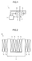
- FIG. 3 is a block diagram showing a configuration of the control unit 5 in the metal strip stabilizer 1 according to the embodiment of the present invention.
- the control unit 5 of the metal strip stabilizer 1 according to the embodiment of the present invention includes an operation amount calculation unit 8, obverse/reverse distribution units 9a and 9b, amplifiers 10a, 10b, 10c, and 10d, and inductors 11a and 11b.
- the operation amount calculation unit 8 performs a so-called PID control such as proportion, differentiation, and integration, etc. to a difference signal between a measured value of displacement of a metal strip by the non-contact displacement sensor 4 and a target value set by an input unit 12, and thereafter outputs a vibration suppression signal and a position correction signal.
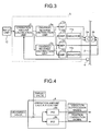
- FIG. 4 is a block diagram explaining an example of a configuration of the operation amount calculation unit 8.
- the operation amount calculation unit 8 includes a vibration suppression PID control unit 8a and a position correction PID control unit 8b.
- the vibration suppression PID control unit 8a is a calculation means to which a difference signal between a measured value and a target value of displacement of a metal strip is input and from which a vibration suppression signal is output
- the position correction PID control unit 8b is a calculation means to which a difference signal between a measured value and a target value of displacement of the metal strip and from which a position correction signal is output.
- the calculation by the vibration suppression PID control unit 8a is responsiveness-focused calculation
- the calculation by the position correction PID control unit 8b is static-attraction-force-focused calculation. That is, the calculation by the vibration suppression PID control unit 8a is set so that a gain for a high frequency component included in an input signal is larger, and the calculation by the position correction PID control unit 8b is set so that a gain for a low frequency component included in an input signal is larger. For example, by setting a derivative gain larger in the vibration suppression PID control unit 8a and setting an integral gain larger in the position correction PID control unit 8b, the above-described setting is realized.
- the high frequency and the low frequency mentioned here mean relatively high or low in comparison between the vibration suppression PID control unit 8a and the position correction PID control unit 8b.
- the fact that the vibration suppression signal includes a lot of the high frequency component and the position correction signal includes a lot of low frequency component means that an average value of the frequency components of the vibration suppression signal is higher than an average value of the frequency components of the position correction signal, and the above-described configuration allows existence of overlapping portion between a frequency distribution of the vibration suppression signal and a frequency distribution of the position correction signal.
- the operation amount calculation unit 8 separates the component used for suppressing vibration and the component used for correcting position from the measured value of displacement of a metal strip by the non-contact displacement sensor 4, and transmits the vibration suppression signal and the position correction signal to the vibration suppression obverse/reverse distribution unit 9a and the position correction obverse/reverse distribution unit 9b, respectively.
- the explanation returns to reference to FIG. 3 .
- the obverse/reverse distribution units 9a and 9b distributes the vibration suppression signal and the position correction signal calculated by the operation amount calculation unit 8 to the electromagnet 3a for use on an obverse surface and the electromagnet 3b for use on a reverse surface of the metal strip 2.
- the amplifier 10a supplies power to the vibration suppression coil of the electromagnet 3a in accordance with the vibration suppression signal distributed by the obverse/reverse distribution unit 9a for use on the obverse surface
- the amplifier 10b supplies power to the position correction coil of the electromagnet 3a in accordance with the position correction signal distributed by the obverse/reverse distribution unit 9b for use at the obverse surface.
- the amplifier 10c supplies power to the vibration suppression coil of the electromagnet 3b in accordance with the vibration suppression signal distributed by the obverse/reverse distribution unit 9a for use on the reverse surface
- the amplifier 10d supplies power to the position correction coil of the electromagnet 3b in accordance with the position correction signal distributed by the obverse/reverse distribution unit 9b for use on the reverse surface.
- FIG. 5 is a schematic view showing an electric circuit of the electromagnet 3a in the metal strip stabilizer 1 according to the embodiment of the present invention.
- an electric circuit corresponding to the electromagnet 3a for use on the obverse surface of the metal strip 2 is schematically shown.
- the vibration suppression amplifier 10a and the position correction amplifier 10b are connected to the vibration suppression coil 7a and the position correction coil 7b, respectively.
- the vibration suppression amplifier 10a supplies power to the vibration suppression coil 7a via an electric circuit in accordance with the input vibration suppression signal.
- the position correction amplifier 10b supplies power to the position correction coil 7b via an electric circuit in accordance with the input position correction signal.
- an electric circuit including the position correction coil 7b and the position correction amplifier 10b includes coils 13a in series as an inductor 11a.
- this is called the counter induced current coil 13a.
- the counter induced current coil 13a In an example of the counter induced current coil 13a shown in FIG. 5 , an example of a coil in which the magnetic circuit 13b is configured by a closed circuit is shown. It should be noted that the coil in which the magnetic circuit 13b is configured by the closed circuit is called a toroidal coil.
- the magnetic circuit 13b of the counter induced current coil 13a can obtain the effect even if it is configured by an open circuit, it is preferable to configure the magnetic circuit 13b of the counter induced current coil 13a by the closed circuit for not being affected by an environmental change by leak, etc. of magnetic flux.
- the counter induced current coil 13a configured in the above-described manner operates as follows in the metal strip stabilizer 1 according to the embodiment of the present invention.
- High frequency current is supposed to flow in the vibration suppression coil 7a in accordance with the vibration frequency of the metal strip 2. Then, since the vibration suppression coil 7a and the position correction coil 7b are configured as concentric coils, a high frequency electromotive force is generated in the position correction coil 7b by a mutual induction.
- the electric current in the position correction coil 7b fluctuated by the electromotive force of the mutual induction, thereby the attraction force of the position correction coil 7b fluctuated, and a bad influence was exerted to the vibration control.
- the counter induced current coil 13a is connected to the electric circuit of the position correction coil 7b, a change in the electric current in the electric circuit of the position correction coil 7b can be suppressed by the inductance of the counter induced current coil 13a.
- a mechanism of suppressing fluctuation in the electric current in the electric circuit of the position correction coil 7b by the counter induced current coil 13a will be explained.
- the induced electromotive force e 1 generated in the vibration suppression coil 7a and the induced electromotive force e 2 generated in the position correction coil 7b are represented by the following equations.
- e 1 - Mdi 2 / dt
- e 2 - Mdi 1 / dt
- M is mutual inductance between the vibration suppression coil 7a and the position correction coil 7b and is represented by the following equation.
- M k ⁇ ⁇ L 1 ⁇ L 2
- k is a coefficient determined in accordance with a shape or a mutual position of the coils
- L 1 is the inductance of the vibration suppression coil 7a
- L 2 is the inductance of the position correction coil 7b.
- a static current for conducting the position correction is supposed to flow in the position correction coil 7b, and a temporal change di 2 /dt in the electric current becomes substantially zero. Therefore, as understood from the above-described equation (4), the very little induced electromotive force e 1 is generated in the vibration suppression coil 7a. That is, the position correction current flowing in the position correction coil 7b exerts a very little influence to the vibration suppression control by the vibration suppression coil 7a.
- the counter induced current coil 13a is connected to the electric circuit of the position correction coil 7b, the current generated by the induced electromotive force is suppressed by a combined inductance of the position correction coil 7b and the counter induced current coil 13a.
- the combined inductance L of the position correction coil 7b and the counter induced current coil 13a is represented by the following equation.
- L L 2 + L 3 where L 2 and L 3 are the inductances of the position correction coil 7b and the counter induced current coil 13a, respectively.
- reactance of alternating current flowing in a coil is in proportion with a frequency of the alternating current and an inductance.
- the vibration suppression signal is a signal including a lot of the high frequency components
- the position correction signal is a signal including a lot of the low frequency components. Therefore, the electric current induced from the vibration suppression coil 7a to the position correction coil 7b is an electric current including a lot of the high frequency components and is affected to a significant degree by a magnitude of the combined inductance L, and thus suppressed.
- the electric current flowing in the position correction coil 7b is not affected to a significant degree by the magnitude of the combined inductance L.
- the movement of the electromagnet is in the primary delay system, and its time constant is given by the equation (2). Therefore, the larger the combined inductance L is, the larger the time constant is, and thus, it is possible to suppress the fluctuation in the electric current.
- the combined inductance L can be increased by increasing the winding number of the counter induced current coil 13a, there are disadvantages in case where the winding number is larger, that a load to an amplifier becomes larger as resistance of an entire circuit becomes larger and more space is necessary for disposing as the counter induced current coil 13a becomes larger in size.
- L 2 and L 3 are the inductances of the position correction coil 7b and the counter induced current coil 13a, respectively, and R 2 and R 3 are resistances of the position correction coil 7b and the counter induced current coil 13a, respectively.
- FIG. 6 is a schematic view showing a part of a commonly used manufacturing line for a hot-dip coated metal strip.
- the metal strip 2 is transferred from a previous step such as a cold-rolling process, undergoes annealing treatment in an annealing furnace 14 of which inside is maintained at non-oxidizing or reducing atmosphere, thereafter undergoes cooling treatment to a level similar to the temperature of molten metal, and is introduced into a hot-dip metal bath 15.
- the metal strip 2 is immersed and passes through the molten metal, and the molten metal adheres on a surface of the metal strip 2. After that, excessive molten metal of the metal strip 2 pulled out from the hot-dip metal bath 15 is shaken off by a gas discharged from a gas wiper 16 to adj ust the adhering amount of the molten metal.
- the metal strip is reheated by using an alloying furnace 17 to conduct an alloying treatment for making a uniform alloy layer depending on usage, for example, in case where the metal strip 2 is used as an outer panel of an automobile.
- the metal strip 2 undergoes a special rust-inhibiting and corrosion-resistant treatment by a chemical processing unit 19 and is wound in a coil, and then shipped.
- FIG. 7 is an enlarged view showing the vicinity (an area indicated by a dotted line in FIG. 6 ) of the gas wiper of the manufacturing line for the hot-dip coated metal strip.
- a drawing roller 20 draws the metal strip 2 into the hot-dip metal bath 15 to make molten metal adhered to the metal strip 2 in the hot-dip metal bath 15, and a pull-up roller 21 pulls up the metal strip 2 to outside the hot-dip metal bath 15.
- the gas wiper 16 is disposed in the middle of a pass line of the pull-up roller 21 pulling up the metal strip 2 and adjusts the adhering amount of the molten metal by shaking off the excessive molten metal adhered to the metal strip 2.
- the electromagnets 3a and 3b and the non-contact displacement sensor 4 of the metal strip stabilizer 1 according to the embodiment of the present invention are disposed at the pass line immediately above the gas wiper 16 to control vibration and position of the metal strip.
- FIG. 8 is a graph showing data measured by a metal strip stabilizer according to a comparative example
- FIG. 9 is a graph showing data measured by the metal strip stabilizer 1 according to the embodiment of the present invention
- FIG. 10 is a graph in which magnitudes of noise included in the measured data shown in FIG. 8 and the measured data shown in FIG. 9 are compared.
- the graph shown in FIG. 8 plots actual values of an electric current in a metal strip stabilizer without the counter induced current coil 13a when a vibration control command at an electric current of 3A at a frequency of 10 Hz is given to the vibration suppression coil 7a, and a control command at a constant current of 0A is given to the position correction coil 7b. It should be noted that, in the graph shown in FIG. 8 , the values of the electric current of the vibration control command is described together.
- the graph shown in FIG. 9 plots actual values of an electric current in the metal strip stabilizer 1 according to the embodiment of the present invention when a vibration control command at an electric current of 3A at a frequency of 10 Hz is given to the vibration suppression coil 7a, and a control command at a constant current of 0A is given to the position correction coil 7b.
- the inductance of the counter induced current coil 13a in this verification experiment is designed so that the serially-combined time constant of the position correction coil 7b and the counter induced current coil 13a is five times of the position correction coil 7b.
- the metal strip stabilizer 1 according to the embodiment of the present invention can avoid lowering of the vibration-controlling performance due to the induced current between the vibration suppression coil and the position correction coil.
- the metal strip stabilizer 1 since the metal strip stabilizer 1 according to the embodiment of the present invention includes the non-contact displacement sensor 4 that measures displacement of the metal strip 2 during online running, the control unit 5 that outputs the vibration suppression signal for suppressing vibration of the metal strip 2 and the position correction signal for correcting a position of the metal strip 2 after a signal is input from the non-contact displacement sensor 4, the vibration suppression coil 7a that generates a magnetic force in accordance with the vibration suppression signal output from the control unit 5, the position correction coil 7b that generates a magnetic force in accordance with the position correction signal output from the control unit 5, the winding number of the second coil being larger than a winding number of the vibration suppression coil 7a, the core 6 around which the vibration suppression coil 7a and the position correction coil 7b are wound concentrically and that induces the magnetic force generated by the vibration suppression coil 7a and the position correction coil 7b to the metal strip 2, and the counter induced current coil 13a that is disposed in series to the electric circuit supplying electricity to the position correction coil 7b; therefore, loss in the
- control unit 5 of the metal strip stabilizer 1 outputs the vibration suppression signal by performing calculation to a difference signal between the signal input from the non-contact displacement sensor 4 and a target value such that the gain of the high frequency component becomes larger than the position correction signal, and outputs the position correction signal by performing calculation such that the gain of the low frequency component becomes larger than the vibration suppression signal; therefore, it is possible to allot an appropriate signal for the vibration control and an appropriate signal for the position correction from the measured displacement amount.
- control unit 5 of the metal strip stabilizer 1 outputs the vibration suppression signal by performing the PID control calculation, in which the derivative gain is set to be larger than the position correction signal, to the difference signal between the signal input from the non-contact displacement sensor 4 and a target value, and outputs the position correction signal by performing the PID control calculation, in which the integral gain is set to be larger than the vibration suppression signal.
- the serially-combined time constant of the position correction coil 7b and the counter induced current coil 13a of the metal strip stabilizer 1 according to the embodiment of the present invention is designed to be within a range of four to ten times of the time constant of the position correction coil 7b.
- the position correction coil 7b and the counter induced current coil 13a of the metal strip stabilizer 1 satisfy the below-described equation: 4 ⁇ L 2 / R 2 ⁇ L 2 + L 3 / R 2 + R 3 ⁇ 10 ⁇ L 2 / R 2 where L 2 and L 3 are the inductances of the position correction coil 7b and the counter induced current coil 13a, respectively, and R 2 and R 3 are the resistances of the position correction coil 7b and the counter induced current coil 13a, respectively.
- the metal strip stabilizer 1 disposes the vibration suppression coils 7a, the position correction coils 7b and the cores 6 on the obverse and the reverse surfaces of the metal strip 2, wherein the vibration suppression coil 7a, the position correction coil 7b and the core 6 for the obverse surface are disposed on the obverse surface, and the vibration suppression coil 7a, the position correction coil 7b and the core 6 for the reverse surface are disposed on the reverse surface; therefore, vibration to and displacement of the obverse and the reverse surfaces of the metal strip 2 can be suppressed.
- control unit 5 of the metal strip stabilizer 1 includes the operation amount calculation unit 8 that outputs the vibration suppression signal suppressing vibration of the metal strip 2 and the position correction signal for correcting the position of the metal strip 2 after a signal is input from the non-contact displacement sensor 4, the obverse/reverse distribution unit 9a that distributes the vibration suppression signal output from the operation amount calculation unit 8 to the vibration suppression coil 7a for the obverse surface and the vibration suppression coil 7a for the reverse surface, the obverse/reverse distribution unit 9b that distributes the position correction signal output from the operation amount calculation unit 8 to the position correction coil 7b for the obverse surface and the position correction coil 7b for the reverse surface, the amplifier 10a that supplies power to the vibration suppression coil 7a for the obverse surface in accordance with the vibration suppression signal for the obverse surface distributed by the obverse/reverse distribution unit 9a, the amplifier 10b that supplies power to the position correction coil 7b for the obverse surface in accordance with the position
- a magnetic circuit 13b of the counter induced current coil 13a is configured as a closed circuit, the metal strip stabilizer 1 according to the embodiment of the present invention is hardly affected by an environmental change due to leak, etc. of magnetic flux.
- a method of manufacturing a hot-dip coated metal strip includes the steps of adhering molten metal to the metal strip 2 passing through the manufacturing line, adjusting the adhering amount of the molten metal by the gas wiper 16 shaking off the excessive molten metal adhering to the metal strip 2, and controlling vibration and a position of the metal strip 2 in a non-contact manner by the above-described metal strip stabilizer 1; therefore, unevenness in the amount of the molten metal adhered to the metal strip 2 can be suppressed.
- the metal strip according to the embodiment of the present invention is manufactured by the above-described manufacturing method, unevenness in the adhering amount of the molten metal can be suppressed.
- the present invention is useful for a manufacturing line for a metal strip, and in particular, a manufacturing line for a hot-dip coated metal strip.
Landscapes
- Chemical & Material Sciences (AREA)
- Engineering & Computer Science (AREA)
- Chemical Kinetics & Catalysis (AREA)
- Materials Engineering (AREA)
- Mechanical Engineering (AREA)
- Metallurgy (AREA)
- Organic Chemistry (AREA)
- Computer Hardware Design (AREA)
- Coating With Molten Metal (AREA)
- Registering, Tensioning, Guiding Webs, And Rollers Therefor (AREA)
- Vibration Prevention Devices (AREA)
- Controlling Rewinding, Feeding, Winding, Or Abnormalities Of Webs (AREA)
Abstract
Description
- The present invention relates to a metal strip stabilizer, a method of manufacturing a hot-dip coated metal strip using that, and a metal strip manufactured by using that.
- In a metal-strip-manufacturing line, suppressing vibration or warp of a metal strip to maintain a stable metal strip pass line contributes to improve not only quality of the metal strip but also efficiency of the manufacturing line.
- For example, in a manufacturing line for a hot-dip coated metal strip, there is a process of adhering molten metal to a surface of a metal strip by passing and immersing the metal strip through a hot-dip metal bath. In this process, in order to suppress generation of unevenness in an amount of the adhering molten metal, an adjustment is performed to shake off the molten metal excessively adhering to the metal strip by discharging wiping gas from a gas wiper provided subsequent to the hot-dip metal bath.
- In this adjustment of the molten metal, it is necessary to discharge the wiping gas from the gas wiper so that pressure is applied to obverse and reverse surfaces of the metal strip uniformly in a plate width direction. Therefore, when a distance between the gas wiper and the metal strip is not constant, that is, in cases where the metal strip is vibrating, the metal strip is warping, or the pass line of the metal strip is leaning to either one of the obverse and reverse surfaces, the pressure of the wiping gas is not uniform in the plate width direction or in a direction in which the metal strip passes. As a result, a problem occurs that unevenness in the amount of the adhering molten metal occurs between the obverse and reverse surfaces of the metal strip, in the plate width direction, or in the direction in which the metal strip passes.
- As a method of solving such a problem, a technique is known that stabilizes the metal strip pass line by suppressing the warp or the vibration of a metal strip in a non-contact manner by using an electromagnet. For example, a method is known that disposes a pair of electromagnets to face each other with respect to a pass line moving a metal strip and makes attraction forces of the electromagnets, while being switched alternatively in accordance with a signal from a position detector disposed separately, act on the metal strip (see Patent Document 1).
- The above-described metal strip vibration control using the electromagnets requires responsiveness of the electromagnets, and the warp correction and the pass line correction require the attraction forces of the electromagnets. It should be noted that a combination of warp correction and pass line correction is hereinafter called the position correction. That is, in order to realize suppressing of vibration and correction of position of a metal strip simultaneously, mutually contradictory characteristics of responsiveness and attraction force are necessary. That is because responsiveness of the electromagnet becomes worsened if the winding number of a coil is increased to increase attraction force of the electromagnet, and on the other hand, attraction force of the electromagnet decreases if the winding number is decreased to improve responsiveness of the electromagnet.
- Then, to address this problem, proposed is a technique for controlling a metal strip in a non-contact manner by using electromagnets having two independent systems of coils, one is for vibration control and the other is for position correction (see Patent Document 2). According to the technique, since vibration control is possible by a vibration suppression coil having a smaller winding number, and warp correction and pass line correction is possible by a position correction coil having a larger winding number, it is possible to perform a control while establishing both vibration-control performance and position-correction performance.
-
- Patent Literature 1: Japanese Laid-open Patent Publication No.
02-62355 - Patent Literature 2: Japanese Laid-open Patent Publication No.
2004-124191 - However, in the above-explained technique for controlling a metal strip in a non-contact manner by using independent electromagnets having two systems of coils, due to mutual induction between the vibration suppression coil and the position correction coil, a change in an electric current in the vibration suppression coil affects an electric current in the position correction coil, and in contrast, a change in the electric current in the position correction coil affects the electric current in the vibration suppression coil. As a result of this, the above-described control technique had a problem that an attraction force different from an attraction force required by a control signal was generated. That is, although the metal strip stabilizer using the electromagnets having two independent systems of coils, one for suppressing vibration and the other for correcting position, can perform the control with establishing both vibration-control performance and position correction performance, there was a problem that a mutual induction between the vibration suppression coil and the position correction coil decreased the vibration suppression performance.
- The present invention has been made in view of the above-mentioned circumstances and an object thereof is to provide a metal strip stabilizer which is capable of avoiding lowering of vibration suppression performance caused by an induced current between a vibration suppression coil and a position correction coil and a method of manufacturing a hot-dip coated metal strip using that.
- To solve the problem described above and achieve the object, a metal strip stabilizer according to the present invention includes: a non-contact displacement sensor that measures displacement of a metal strip during online running; a control unit that outputs a vibration suppression signal for suppressing vibration of the metal strip and a position correction signal for correcting a position of the metal strip after a signal is input from the non-contact displacement sensor; a first coil that generates a magnetic force in accordance with the vibration suppression signal output from the control unit; a second coil that generates a magnetic force in accordance with the position correction signal output from the control unit, a winding number of the second coil being larger than a winding number of the first coil; a core around which the first coil and the second coil are wound concentrically and that induces the magnetic force generated by the first coil and the second coil to the metal strip; and a third coil that is disposed in series to an electric circuit supplying electricity to the second coil.
- According to the metal strip stabilizer of the present invention and the method of manufacturing a hot-dip coated metal strip, it is possible to avoid lowering of the vibration suppression performance caused by an induced current between the vibration suppression coil and the position correction coil.
-
-
FIG. 1 is a schematic view showing a configuration of a metal strip stabilizer according to an embodiment of the present invention. -
FIG. 2 is a schematic view showing an example of an electromagnet used in the metal strip stabilizer according to the embodiment of the present invention. -
FIG. 3 is a block diagram showing a configuration of a control unit in the metal strip stabilizer according to the embodiment of the present invention. -
FIG. 4 is a block diagram explaining an example of a configuration of an operation amount calculation unit. -
FIG. 5 is a schematic view showing an electric circuit of the electromagnet in the metal strip stabilizer according to the embodiment of the present invention. -
FIG. 6 is a schematic view showing a part of a commonly used manufacturing line for a hot-dip coated metal strip. -
FIG. 7 is an enlarged view showing the vicinity of a gas wiper of the manufacturing line for a hot-dip coated metal strip. -
FIG. 8 is a graph showing data measured by a metal strip stabilizer according to a comparative example. -
FIG. 9 is a graph showing data measured by the metal strip stabilizer according to the embodiment of the present invention. -
FIG. 10 is a graph in which magnitudes of noise included in the measured data shown inFIG. 8 and the measured data shown inFIG. 9 are compared. - Hereinafter, a metal strip stabilizer according to an embodiment of the present invention will be explained with reference to the drawings.
-
FIG. 1 is a schematic view showing a configuration of ametal strip stabilizer 1 according to the embodiment of the present invention. As shown inFIG. 1 , thestabilizer 1 according to the embodiment of the present invention includes a pair ofelectromagnets metal strip 2 running in a direction of an arrow A in the drawing, anon-contact displacement sensor 4 disposed in the vicinity of theelectromagnets control unit 5 controlling theelectromagnets non-contact displacement sensor 4. -
FIG. 2 is a schematic view showing an example of theelectromagnet 3a used in themetal strip stabilizer 1 according to the embodiment of the present invention. It should be noted that herein only theelectromagnet 3a for use of an obverse surface of themetal strip 2 will be explained, the following explanation is effective for theelectromagnet 3b for use of a reverse surface of themetal strip 2. Theelectromagnet 3a shown inFIG. 2 is configured as a concentric coil consisting of acoil 7a and acoil 7b constituted by winding two coils concentrically around acore 6. Twocoils coils vibration suppression coil 7a and the other one having a larger winding number is theposition correction coil 7b. - Although high responsiveness is required for the
vibration suppression coil 7a in order to be capable of fully following a vibration frequency (usually, a natural vibration frequency of bending or warp of a metal strip) of thetarget metal strip 2, but, for suppressing vibration at a natural frequency of a metal strip, a large attraction force is not required. Therefore, the winding number of thevibration suppression coil 7a is configured to be smaller than that of theposition correction coil 7b. - On the other hand, although high responsiveness is not required for the
position correction coil 7b, it is desirable to be capable of generating a larger attraction force with a smaller current. Therefore, it is preferable that the winding number of theposition correction coil 7b is large within a range in which a size and a value of electric resistance of theelectromagnet 3a are not too large. - In the following, relationship between the winding number of a coil and responsiveness and attraction force of an electromagnet will be explained.
- The movement of the electromagnet is represented by an equation (1):

where e indicates an applied voltage, i indicates an electric current flowing in the coil, L indicates an inductance of the coil, and R indicates resistance of the coil. - As shown in the equation (1), the electric current i flowing in the coil is in the primary delay system relative to the applied voltage e, and its time constant T is represented by an equation (2):

where the inductance L of the coil is in proportion with the square of a winding number N of the coil, and the resistance R of the coil is in proportion with the winding number N of the coil. Therefore, according to the equation (2), the time constant T is supposed to be in proportion with the winding number N of the coil. This means that, the larger the winding number of the coil is, the larger the time constant becomes and the more responsiveness decreases. - On the other hand, as shown in an equation (3), the attraction force F of the electromagnet is in proportion with the square of the winding number N of the coil and the square of the electric current i flowing in the coil.

Therefore, for obtaining the larger attraction force with the same current, it is advantageous to increase the winding number N of the coil. - The above indicates that, although it is preferable to decrease the winding number N of the coil to improve responsiveness, it is preferable to increase the winding number N of the coil to intensify an attraction force. Therefore, in the
electromagnet 3a according to the embodiment of the present invention, the winding number of thevibration suppression coil 7a which needs the high responsiveness but no large attraction force is configured to be smaller than the winding number of theposition correction coil 7b. On the other hand, the winding number of theposition correction coil 7b which needs the large attraction force but no high responsiveness is configured to be larger than the winding number of thevibration suppression coil 7a. -
FIG. 3 is a block diagram showing a configuration of thecontrol unit 5 in themetal strip stabilizer 1 according to the embodiment of the present invention. As shown inFIG. 3 , thecontrol unit 5 of themetal strip stabilizer 1 according to the embodiment of the present invention includes an operationamount calculation unit 8, obverse/reverse distribution units 9a and 9b,amplifiers inductors - The operation
amount calculation unit 8 performs a so-called PID control such as proportion, differentiation, and integration, etc. to a difference signal between a measured value of displacement of a metal strip by thenon-contact displacement sensor 4 and a target value set by aninput unit 12, and thereafter outputs a vibration suppression signal and a position correction signal.FIG. 4 is a block diagram explaining an example of a configuration of the operationamount calculation unit 8. - As shown in
FIG. 4 , the operationamount calculation unit 8 includes a vibration suppressionPID control unit 8a and a position correctionPID control unit 8b. The vibration suppressionPID control unit 8a is a calculation means to which a difference signal between a measured value and a target value of displacement of a metal strip is input and from which a vibration suppression signal is output, and the position correctionPID control unit 8b is a calculation means to which a difference signal between a measured value and a target value of displacement of the metal strip and from which a position correction signal is output. - Herein the calculation by the vibration suppression
PID control unit 8a is responsiveness-focused calculation, and the calculation by the position correctionPID control unit 8b is static-attraction-force-focused calculation. That is, the calculation by the vibration suppressionPID control unit 8a is set so that a gain for a high frequency component included in an input signal is larger, and the calculation by the position correctionPID control unit 8b is set so that a gain for a low frequency component included in an input signal is larger. For example, by setting a derivative gain larger in the vibration suppressionPID control unit 8a and setting an integral gain larger in the position correctionPID control unit 8b, the above-described setting is realized. - The high frequency and the low frequency mentioned here mean relatively high or low in comparison between the vibration suppression
PID control unit 8a and the position correctionPID control unit 8b. In addition, according to the above-described configuration, the fact that the vibration suppression signal includes a lot of the high frequency component and the position correction signal includes a lot of low frequency component means that an average value of the frequency components of the vibration suppression signal is higher than an average value of the frequency components of the position correction signal, and the above-described configuration allows existence of overlapping portion between a frequency distribution of the vibration suppression signal and a frequency distribution of the position correction signal. - By configuring the operation
amount calculation unit 8 in the above-described manner, the operationamount calculation unit 8 separates the component used for suppressing vibration and the component used for correcting position from the measured value of displacement of a metal strip by thenon-contact displacement sensor 4, and transmits the vibration suppression signal and the position correction signal to the vibration suppression obverse/reverse distribution unit 9a and the position correction obverse/reverse distribution unit 9b, respectively. - The explanation returns to reference to
FIG. 3 . The obverse/reverse distribution units 9a and 9b distributes the vibration suppression signal and the position correction signal calculated by the operationamount calculation unit 8 to theelectromagnet 3a for use on an obverse surface and theelectromagnet 3b for use on a reverse surface of themetal strip 2. Theamplifier 10a supplies power to the vibration suppression coil of theelectromagnet 3a in accordance with the vibration suppression signal distributed by the obverse/reverse distribution unit 9a for use on the obverse surface, and theamplifier 10b supplies power to the position correction coil of theelectromagnet 3a in accordance with the position correction signal distributed by the obverse/reverse distribution unit 9b for use at the obverse surface. On the other hand, theamplifier 10c supplies power to the vibration suppression coil of theelectromagnet 3b in accordance with the vibration suppression signal distributed by the obverse/reverse distribution unit 9a for use on the reverse surface, and theamplifier 10d supplies power to the position correction coil of theelectromagnet 3b in accordance with the position correction signal distributed by the obverse/reverse distribution unit 9b for use on the reverse surface. -
FIG. 5 is a schematic view showing an electric circuit of theelectromagnet 3a in themetal strip stabilizer 1 according to the embodiment of the present invention. Herein, due to limitations of a space, only an electric circuit corresponding to theelectromagnet 3a for use on the obverse surface of themetal strip 2 is schematically shown. - As shown in
FIG. 5 , thevibration suppression amplifier 10a and theposition correction amplifier 10b are connected to thevibration suppression coil 7a and theposition correction coil 7b, respectively. Thevibration suppression amplifier 10a supplies power to thevibration suppression coil 7a via an electric circuit in accordance with the input vibration suppression signal. Theposition correction amplifier 10b supplies power to theposition correction coil 7b via an electric circuit in accordance with the input position correction signal. - Furthermore, an electric circuit including the
position correction coil 7b and theposition correction amplifier 10b includescoils 13a in series as aninductor 11a. Hereinafter, this is called the counter inducedcurrent coil 13a. In an example of the counter inducedcurrent coil 13a shown inFIG. 5 , an example of a coil in which themagnetic circuit 13b is configured by a closed circuit is shown. It should be noted that the coil in which themagnetic circuit 13b is configured by the closed circuit is called a toroidal coil. Although themagnetic circuit 13b of the counter inducedcurrent coil 13a can obtain the effect even if it is configured by an open circuit, it is preferable to configure themagnetic circuit 13b of the counter inducedcurrent coil 13a by the closed circuit for not being affected by an environmental change by leak, etc. of magnetic flux. - The counter induced
current coil 13a configured in the above-described manner operates as follows in themetal strip stabilizer 1 according to the embodiment of the present invention. - High frequency current is supposed to flow in the
vibration suppression coil 7a in accordance with the vibration frequency of themetal strip 2. Then, since thevibration suppression coil 7a and theposition correction coil 7b are configured as concentric coils, a high frequency electromotive force is generated in theposition correction coil 7b by a mutual induction. - In a conventional metal strip stabilizer, the electric current in the
position correction coil 7b fluctuated by the electromotive force of the mutual induction, thereby the attraction force of theposition correction coil 7b fluctuated, and a bad influence was exerted to the vibration control. However, in themetal strip stabilizer 1 according to the embodiment of the present invention, since the counter inducedcurrent coil 13a is connected to the electric circuit of theposition correction coil 7b, a change in the electric current in the electric circuit of theposition correction coil 7b can be suppressed by the inductance of the counter inducedcurrent coil 13a. Hereinafter, a mechanism of suppressing fluctuation in the electric current in the electric circuit of theposition correction coil 7b by the counter inducedcurrent coil 13a will be explained. - When the electric current flowing in the
vibration suppression coil 7a is i1 and the electric current flowing in theposition correction coil 7b is i2, the induced electromotive force e1 generated in thevibration suppression coil 7a and the induced electromotive force e2 generated in theposition correction coil 7b are represented by the following equations.

where M is mutual inductance between thevibration suppression coil 7a and theposition correction coil 7b and is represented by the following equation.
where k is a coefficient determined in accordance with a shape or a mutual position of the coils, L1 is the inductance of thevibration suppression coil 7a, and L2 is the inductance of theposition correction coil 7b. - A static current for conducting the position correction is supposed to flow in the
position correction coil 7b, and a temporal change di2/dt in the electric current becomes substantially zero. Therefore, as understood from the above-described equation (4), the very little induced electromotive force e1 is generated in thevibration suppression coil 7a. That is, the position correction current flowing in theposition correction coil 7b exerts a very little influence to the vibration suppression control by thevibration suppression coil 7a. - On the other hand, a dynamic current for suppressing vibration is supposed to flow in the
vibration suppression coil 7a, and so a temporal change di1/dt in the current is large. Therefore, as understood from the above-described equation (5), the large induced electromotive force e2 is generated in theposition correction coil 7b. - However, in the
metal strip stabilizer 1 according to the embodiment of the present invention, since the counter inducedcurrent coil 13a is connected to the electric circuit of theposition correction coil 7b, the current generated by the induced electromotive force is suppressed by a combined inductance of theposition correction coil 7b and the counter inducedcurrent coil 13a. - As explained with reference to
FIG. 5 , since theposition correction coil 7b and the counter inducedcurrent coil 13a are connected in series, the combined inductance L of theposition correction coil 7b and the counter inducedcurrent coil 13a is represented by the following equation.
where L2 and L3 are the inductances of theposition correction coil 7b and the counter inducedcurrent coil 13a, respectively. - By the way, reactance of alternating current flowing in a coil is in proportion with a frequency of the alternating current and an inductance. On the other hand, as described above, the vibration suppression signal is a signal including a lot of the high frequency components, and the position correction signal is a signal including a lot of the low frequency components. Therefore, the electric current induced from the
vibration suppression coil 7a to theposition correction coil 7b is an electric current including a lot of the high frequency components and is affected to a significant degree by a magnitude of the combined inductance L, and thus suppressed. On the other hand, the electric current flowing in theposition correction coil 7b is not affected to a significant degree by the magnitude of the combined inductance L. In addition, as understood from the equation (7), since the magnitude of the inductance L2 of theposition correction coil 7b does not change even if the counter inducedcurrent coil 13a is connected and the combined inductance L becomes large, characteristics of an electromagnet by theposition correction coil 7b do not change. - As described above, the movement of the electromagnet is in the primary delay system, and its time constant is given by the equation (2). Therefore, the larger the combined inductance L is, the larger the time constant is, and thus, it is possible to suppress the fluctuation in the electric current. On the other hand, although the combined inductance L can be increased by increasing the winding number of the counter induced
current coil 13a, there are disadvantages in case where the winding number is larger, that a load to an amplifier becomes larger as resistance of an entire circuit becomes larger and more space is necessary for disposing as the counter inducedcurrent coil 13a becomes larger in size.. - Then, it is necessary to determine the inductance of the counter induced current coil in consideration of the vibration-controlling performance and the above-described disadvantage. Based on the later-described demonstration experiment for the effect according to the embodiment of the present invention, it is preferable to set a serially-combined time constant for the
position correction coil 7b and the counter inducedcurrent coil 13a within a range of four to ten times of theposition correction coil 7b. In another expression of this condition based on the relation of the equation (2), it is preferable to design themetal strip stabilizer 1 according to the embodiment of the present invention so that thevibration suppression coil 7a, theposition correction coil 7b, and the countercurrent coil 13a satisfy the range of the following equation.
where L2 and L3 are the inductances of theposition correction coil 7b and the counter inducedcurrent coil 13a, respectively, and R2 and R3 are resistances of theposition correction coil 7b and the counter inducedcurrent coil 13a, respectively. - It should be noted that, disposing the counter induced
current coil 13a worsens the responsiveness of theposition correction coil 7b intentionally. However, as described above, since the responsiveness is not required for theposition correction coil 7b, it is not affected to the position correction for the metal strip. As a result, it is possible to suppress the mutual induced current by thevibration suppression coil 7a and theposition correction coil 7b, to avoid a bad influence to the vibration control, and to make the responsiveness of thevibration suppression coil 7a consistent with the attraction force of theposition correction coil 7b. - Next, an example of a configuration is explained in which the
metal strip stabilizer 1 according to the embodiment of the present invention is disposed in a manufacturing line for a hot-dip coated metal strip. -
FIG. 6 is a schematic view showing a part of a commonly used manufacturing line for a hot-dip coated metal strip. In the manufacturing line for the hot-dip coated metal strip shown inFIG. 6 , themetal strip 2 is transferred from a previous step such as a cold-rolling process, undergoes annealing treatment in anannealing furnace 14 of which inside is maintained at non-oxidizing or reducing atmosphere, thereafter undergoes cooling treatment to a level similar to the temperature of molten metal, and is introduced into a hot-dip metal bath 15. - In the hot-
dip metal bath 15, themetal strip 2 is immersed and passes through the molten metal, and the molten metal adheres on a surface of themetal strip 2. After that, excessive molten metal of themetal strip 2 pulled out from the hot-dip metal bath 15 is shaken off by a gas discharged from agas wiper 16 to adj ust the adhering amount of the molten metal. - In a subsequent process, there is a case where the metal strip is reheated by using an alloying
furnace 17 to conduct an alloying treatment for making a uniform alloy layer depending on usage, for example, in case where themetal strip 2 is used as an outer panel of an automobile. After passing through acooling zone 18, themetal strip 2 undergoes a special rust-inhibiting and corrosion-resistant treatment by achemical processing unit 19 and is wound in a coil, and then shipped. -
FIG. 7 is an enlarged view showing the vicinity (an area indicated by a dotted line inFIG. 6 ) of the gas wiper of the manufacturing line for the hot-dip coated metal strip. As shown inFIG. 7 , in the vicinity of thegas wiper 16 of the manufacturing line for a hot-dip coated metal strip, a drawingroller 20 draws themetal strip 2 into the hot-dip metal bath 15 to make molten metal adhered to themetal strip 2 in the hot-dip metal bath 15, and a pull-uproller 21 pulls up themetal strip 2 to outside the hot-dip metal bath 15. Thegas wiper 16 is disposed in the middle of a pass line of the pull-uproller 21 pulling up themetal strip 2 and adjusts the adhering amount of the molten metal by shaking off the excessive molten metal adhered to themetal strip 2. - The
electromagnets non-contact displacement sensor 4 of themetal strip stabilizer 1 according to the embodiment of the present invention are disposed at the pass line immediately above thegas wiper 16 to control vibration and position of the metal strip. By this disposition, as a result that distance between thegas wiper 16 and themetal strip 2 becomes constant, pressure by the wiping gas becomes uniform, and unevenness in the amount of the molten metal adhering to themetal strip 2 can be suppressed. - Finally, a verification experiment for the effect of the
metal strip stabilizer 1 according to the embodiment of the present invention will be explained.FIG. 8 is a graph showing data measured by a metal strip stabilizer according to a comparative example, andFIG. 9 is a graph showing data measured by themetal strip stabilizer 1 according to the embodiment of the present invention. In addition,FIG. 10 is a graph in which magnitudes of noise included in the measured data shown inFIG. 8 and the measured data shown inFIG. 9 are compared. - The graph shown in
FIG. 8 plots actual values of an electric current in a metal strip stabilizer without the counter inducedcurrent coil 13a when a vibration control command at an electric current of 3A at a frequency of 10 Hz is given to thevibration suppression coil 7a, and a control command at a constant current of 0A is given to theposition correction coil 7b. It should be noted that, in the graph shown inFIG. 8 , the values of the electric current of the vibration control command is described together. - As understood from the graph shown in
FIG. 8 , in the comparative example, although the constant current of 0A is supposed to flow in theposition correction coil 7b, a current is detected as an actual value. This current flowing in theposition correction coil 7b is an induced current which is generated at theposition correction coil 7b side by electromagnetic induction due to the fluctuation in the current for the vibration control flowing in thevibration suppression coil 7a. Furthermore, according to the graph shown inFIG. 8 , by the fluctuation in the induced current flowing in theposition correction coil 7b, an induced current also flows at thevibration suppression coil 7a side and disturbance is generated in the actual current for the vibration control. - The graph shown in
FIG. 9 plots actual values of an electric current in themetal strip stabilizer 1 according to the embodiment of the present invention when a vibration control command at an electric current of 3A at a frequency of 10 Hz is given to thevibration suppression coil 7a, and a control command at a constant current of 0A is given to theposition correction coil 7b. It should be noted that the inductance of the counter inducedcurrent coil 13a in this verification experiment is designed so that the serially-combined time constant of theposition correction coil 7b and the counter inducedcurrent coil 13a is five times of theposition correction coil 7b. - As understood from the graph shown in
FIG. 9 , influence by the induced current is very little in thevibration suppression coil 7a and theposition correction coil 7b according to the embodiment of the present invention, and the control precisely following the control commands is realized. In addition, as understood from a comparison of the graphs shown inFIGS. 8 and9 , although, in thevibration suppression coil 7a and theposition correction coil 7b in the comparative example, a vicious circle occurs in which the fluctuation in the induced current induced to theposition correction coil 7b further affects thevibration suppression coil 7a, this vicious cycle does not occur in thevibration suppression coil 7a and theposition correction coil 7b according to the embodiment of the present invention. Moreover, as understood from the graph shown inFIG. 10 , according to themetal strip stabilizer 1 according to the embodiment of the present invention, it is possible to reduce the induced current which disturbs the vibration control to one-eleventh. That is, themetal strip stabilizer 1 according to the embodiment of the present invention can avoid lowering of the vibration-controlling performance due to the induced current between the vibration suppression coil and the position correction coil. - As above described, since the
metal strip stabilizer 1 according to the embodiment of the present invention includes thenon-contact displacement sensor 4 that measures displacement of themetal strip 2 during online running, thecontrol unit 5 that outputs the vibration suppression signal for suppressing vibration of themetal strip 2 and the position correction signal for correcting a position of themetal strip 2 after a signal is input from thenon-contact displacement sensor 4, thevibration suppression coil 7a that generates a magnetic force in accordance with the vibration suppression signal output from thecontrol unit 5, theposition correction coil 7b that generates a magnetic force in accordance with the position correction signal output from thecontrol unit 5, the winding number of the second coil being larger than a winding number of thevibration suppression coil 7a, thecore 6 around which thevibration suppression coil 7a and theposition correction coil 7b are wound concentrically and that induces the magnetic force generated by thevibration suppression coil 7a and theposition correction coil 7b to themetal strip 2, and the counter inducedcurrent coil 13a that is disposed in series to the electric circuit supplying electricity to theposition correction coil 7b; therefore, loss in the vibration suppression performance caused by the induced current between thevibration suppression coil 7a and theposition correction coil 7b may be prevented. - Here, the
control unit 5 of themetal strip stabilizer 1 according to the embodiment of the present invention outputs the vibration suppression signal by performing calculation to a difference signal between the signal input from thenon-contact displacement sensor 4 and a target value such that the gain of the high frequency component becomes larger than the position correction signal, and outputs the position correction signal by performing calculation such that the gain of the low frequency component becomes larger than the vibration suppression signal; therefore, it is possible to allot an appropriate signal for the vibration control and an appropriate signal for the position correction from the measured displacement amount. Moreover, it is preferable that thecontrol unit 5 of themetal strip stabilizer 1 according to the embodiment of the present invention outputs the vibration suppression signal by performing the PID control calculation, in which the derivative gain is set to be larger than the position correction signal, to the difference signal between the signal input from thenon-contact displacement sensor 4 and a target value, and outputs the position correction signal by performing the PID control calculation, in which the integral gain is set to be larger than the vibration suppression signal. - Moreover, it is preferable that the serially-combined time constant of the
position correction coil 7b and the counter inducedcurrent coil 13a of themetal strip stabilizer 1 according to the embodiment of the present invention is designed to be within a range of four to ten times of the time constant of theposition correction coil 7b. Alternatively, it is preferable that theposition correction coil 7b and the counter inducedcurrent coil 13a of themetal strip stabilizer 1 according to the embodiment of the present invention satisfy the below-described equation:
where L2 and L3 are the inductances of theposition correction coil 7b and the counter inducedcurrent coil 13a, respectively, and R2 and R3 are the resistances of theposition correction coil 7b and the counter inducedcurrent coil 13a, respectively. - Moreover, since the
metal strip stabilizer 1 according to the embodiment of the present invention disposes thevibration suppression coils 7a, the position correction coils 7b and thecores 6 on the obverse and the reverse surfaces of themetal strip 2, wherein thevibration suppression coil 7a, theposition correction coil 7b and thecore 6 for the obverse surface are disposed on the obverse surface, and thevibration suppression coil 7a, theposition correction coil 7b and thecore 6 for the reverse surface are disposed on the reverse surface; therefore, vibration to and displacement of the obverse and the reverse surfaces of themetal strip 2 can be suppressed. - Since the control unit 5 of the metal strip stabilizer 1 according to the embodiment of the present invention includes the operation amount calculation unit 8 that outputs the vibration suppression signal suppressing vibration of the metal strip 2 and the position correction signal for correcting the position of the metal strip 2 after a signal is input from the non-contact displacement sensor 4, the obverse/reverse distribution unit 9a that distributes the vibration suppression signal output from the operation amount calculation unit 8 to the vibration suppression coil 7a for the obverse surface and the vibration suppression coil 7a for the reverse surface, the obverse/reverse distribution unit 9b that distributes the position correction signal output from the operation amount calculation unit 8 to the position correction coil 7b for the obverse surface and the position correction coil 7b for the reverse surface, the amplifier 10a that supplies power to the vibration suppression coil 7a for the obverse surface in accordance with the vibration suppression signal for the obverse surface distributed by the obverse/reverse distribution unit 9a, the amplifier 10b that supplies power to the position correction coil 7b for the obverse surface in accordance with the position correction signal for the obverse surface distributed by the obverse/reverse distribution unit 9b, the amplifier 10c that supplies power to the vibration suppression coil 7a for the reverse surface in accordance with the vibration suppression signal for the reverse surface distributed by the obverse/reverse distribution unit 9a, and the amplifier 10d that supplies power to the position correction coil 7b for the reverse surface in accordance with the position correction signal for the reverse surface distributed by the obverse/reverse distribution unit 9b, and the counter induced current coils 13a are disposed at electric circuits between the amplifier 10b and the position correction coil 7b for the obverse surface and between the amplifier 10d and the position correction coil 7b for the reverse surface, respectively; therefore, both vibration to and displacement of the obverse and the reverse surfaces of the metal strip 2 can be suppressed.
- Moreover, since a
magnetic circuit 13b of the counter inducedcurrent coil 13a is configured as a closed circuit, themetal strip stabilizer 1 according to the embodiment of the present invention is hardly affected by an environmental change due to leak, etc. of magnetic flux. - Furthermore, a method of manufacturing a hot-dip coated metal strip according to the embodiment of the present invention includes the steps of adhering molten metal to the
metal strip 2 passing through the manufacturing line, adjusting the adhering amount of the molten metal by thegas wiper 16 shaking off the excessive molten metal adhering to themetal strip 2, and controlling vibration and a position of themetal strip 2 in a non-contact manner by the above-describedmetal strip stabilizer 1; therefore, unevenness in the amount of the molten metal adhered to themetal strip 2 can be suppressed. - Moreover, since the metal strip according to the embodiment of the present invention is manufactured by the above-described manufacturing method, unevenness in the adhering amount of the molten metal can be suppressed.
- As described above, although the present invention is explained based on the embodiment, when carrying out the present invention, the present invention is not limited by the wordings and the drawings constituting a part of the disclosure of the present invention by the present embodiment.
- The present invention is useful for a manufacturing line for a metal strip, and in particular, a manufacturing line for a hot-dip coated metal strip.
-
- 1
- metal strip stabilizer
- 2
- metal strip
- 3a, 3b
- electromagnet
- 4
- non-contact displacement sensor
- 5
- control unit
- 6
- core
- 7a
- vibration suppression coil
- 7b
- position correction coil
- 8
- operation amount calculation unit
- 9a,
- 9b obverse/reverse distribution unit
- 10a to 10d
- amplifier
- 11a, 11b
- inductor
- 12
- input unit
- 13a
- counter induced current coil
- 13b
- magnetic circuit
- 14
- annealing furnace
- 15
- hot-dip metal bath
- 16
- gas wiper
- 17
- alloying furnace
- 18
- cooling zone
- 19
- chemical processing unit
- 20
- drawing roller
- 21
- pull-up roller
Claims (8)
- A metal strip stabilizer comprising:a non-contact displacement sensor that measures displacement of a metal strip during online running;a control unit that outputs a vibration suppression signal for suppressing vibration of the metal strip and a position correction signal for correcting a position of the metal strip after a signal is input from the non-contact displacement sensor;a first coil that generates a magnetic force in accordance with the vibration suppression signal output from the control unit;a second coil that generates a magnetic force in accordance with the position correction signal output from the control unit, a winding number of the second coil being larger than a winding number of the first coil;a core around which the first coil and the second coil are wound concentrically and that induces the magnetic force generated by the first coil and the second coil to the metal strip; anda third coil that is disposed in series to an electric circuit supplying electricity to the second coil.
- The metal strip stabilizer according to claim 1, wherein the control unit outputs the vibration suppression signal by performing calculation to a difference signal between the signal input from the non-contact displacement sensor and a target value such that a gain of a high frequency component becomes larger than the position correction signal, and outputs the position correction signal by performing calculation such that a gain of a low frequency component becomes larger than the vibration suppression signal.
- The metal strip stabilizer according to claim 1 or 2, wherein the control unit outputs the vibration suppression signal by performing a PID control calculation, in which derivative gain is set to be larger than the position correction signal, to a difference signal between the signal input from the non-contact displacement sensor and a target value, and outputs the position correction signal by performing a PID control calculation, in which integral gain is set to be larger than the vibration suppression signal.
- The metal strip stabilizer according to any one of claims 1 to 3, wherein a serially-combined time constant of the second coil and the third coil is designed to be within a range of four to ten times of a time constant of the second coil.
- The metal strip stabilizer according to any one of claims 1 to 4, wherein the second coil and the third coil satisfy an equation:

where L2 and L3 are inductances of the second coil and the third coil, respectively, and R2 and R3 are resistances of the second coil and the third coil, respectively. - The metal strip stabilizer according to any one of claims 1 to 5, wherein a magnetic circuit of the third coil is configured as a closed circuit.
- A method of manufacturing a hot-dip coated metal strip, the method comprising the steps of:adhering molten metal to a metal strip passing through a manufacturing line;adjusting a adhering amount of the molten metal by a gas wiper shaking off excessive molten metal adhering to the metal strip; andcontrolling vibration and a position of the metal strip in a non-contact manner by the metal strip stabilizer of any one of claims 1 to 6.
- A metal strip manufactured by the method according to claim 7.
Applications Claiming Priority (3)
| Application Number | Priority Date | Filing Date | Title |
|---|---|---|---|
| JP2011174204 | 2011-08-09 | ||
| JP2012168154A JP5263433B2 (en) | 2011-08-09 | 2012-07-30 | Metal strip stabilizer and hot-plated metal strip manufacturing method |
| PCT/JP2012/070115 WO2013022004A1 (en) | 2011-08-09 | 2012-08-07 | Metal strip stabilizer, method for manufacturing hot dipped metal strip, and metal strip |
Publications (3)
| Publication Number | Publication Date |
|---|---|
| EP2743368A1 true EP2743368A1 (en) | 2014-06-18 |
| EP2743368A4 EP2743368A4 (en) | 2015-04-08 |
| EP2743368B1 EP2743368B1 (en) | 2016-06-01 |
Family
ID=47668511
Family Applications (1)
| Application Number | Title | Priority Date | Filing Date |
|---|---|---|---|
| EP12821917.7A Active EP2743368B1 (en) | 2011-08-09 | 2012-08-07 | Metal strip stabilizer |
Country Status (5)
| Country | Link |
|---|---|
| EP (1) | EP2743368B1 (en) |
| JP (1) | JP5263433B2 (en) |
| KR (1) | KR101470906B1 (en) |
| CN (1) | CN103717778B (en) |
| WO (1) | WO2013022004A1 (en) |
Cited By (2)
| Publication number | Priority date | Publication date | Assignee | Title |
|---|---|---|---|---|
| AU2016374757B2 (en) * | 2015-12-25 | 2019-07-04 | Jfe Steel Corporation | Metal Strip Stabilizer and Method for Manufacturing Hot-Dip Coated Metal Strip |
| US10876194B2 (en) | 2014-11-20 | 2020-12-29 | Jfe Steel Corporation | Metal strip stabilization apparatus and method for manufacturing hot-dip coated metal strip using same |
Families Citing this family (1)
| Publication number | Priority date | Publication date | Assignee | Title |
|---|---|---|---|---|
| JP6112040B2 (en) * | 2014-02-26 | 2017-04-12 | Jfeスチール株式会社 | Non-contact control device for metal strip and method of manufacturing hot-dip metal strip |
Family Cites Families (7)
| Publication number | Priority date | Publication date | Assignee | Title |
|---|---|---|---|---|
| JP2629029B2 (en) | 1988-08-26 | 1997-07-09 | 川崎製鉄株式会社 | Steel plate vibration suppression and position control device |
| DE10014867A1 (en) * | 2000-03-24 | 2001-09-27 | Sms Demag Ag | Process for the hot dip galvanizing of steel strips comprises continuously correcting the electrochemical field vertically to the surface of the strip to stabilize a middle |
| JP3876810B2 (en) * | 2002-10-03 | 2007-02-07 | Jfeスチール株式会社 | Metal band damping device and metal band manufacturing method |
| DE10255994A1 (en) * | 2002-11-30 | 2004-06-09 | Sms Demag Ag | Method and device for hot-dip coating a metal strand |
| DE102004060425B3 (en) * | 2004-08-24 | 2006-04-27 | Betriebsforschungsinstitut VDEh - Institut für angewandte Forschung GmbH | Process for coil coating |
| JP2009141255A (en) * | 2007-12-10 | 2009-06-25 | Kobe Steel Ltd | Superconductive electromagnet |
| JP5223451B2 (en) * | 2008-05-17 | 2013-06-26 | Jfeスチール株式会社 | Method for producing hot-dip metal strip |
-
2012
- 2012-07-30 JP JP2012168154A patent/JP5263433B2/en active Active
- 2012-08-07 WO PCT/JP2012/070115 patent/WO2013022004A1/en not_active Ceased
- 2012-08-07 CN CN201280038441.XA patent/CN103717778B/en active Active
- 2012-08-07 KR KR1020147003123A patent/KR101470906B1/en active Active
- 2012-08-07 EP EP12821917.7A patent/EP2743368B1/en active Active
Cited By (2)
| Publication number | Priority date | Publication date | Assignee | Title |
|---|---|---|---|---|
| US10876194B2 (en) | 2014-11-20 | 2020-12-29 | Jfe Steel Corporation | Metal strip stabilization apparatus and method for manufacturing hot-dip coated metal strip using same |
| AU2016374757B2 (en) * | 2015-12-25 | 2019-07-04 | Jfe Steel Corporation | Metal Strip Stabilizer and Method for Manufacturing Hot-Dip Coated Metal Strip |
Also Published As
| Publication number | Publication date |
|---|---|
| JP5263433B2 (en) | 2013-08-14 |
| CN103717778B (en) | 2015-04-29 |
| EP2743368B1 (en) | 2016-06-01 |
| JP2013053367A (en) | 2013-03-21 |
| KR20140035516A (en) | 2014-03-21 |
| EP2743368A4 (en) | 2015-04-08 |
| WO2013022004A1 (en) | 2013-02-14 |
| KR101470906B1 (en) | 2014-12-09 |
| CN103717778A (en) | 2014-04-09 |
Similar Documents
| Publication | Publication Date | Title |
|---|---|---|
| KR101997790B1 (en) | Metal strip stabilization apparatus and method for manufacturing hot-dipped metal strip using same | |
| EP2743368B1 (en) | Metal strip stabilizer | |
| Liu et al. | A real-time controllable electromagnetic vibration isolator based on magnetorheological elastomer with quasi-zero stiffness characteristic | |
| EP2265089B1 (en) | Induction heating apparatus and induction heating method | |
| JP2015515143A (en) | Soft magnetic core with position-dependent permeability | |
| CA2697194C (en) | Process and hot-dip coating system for stabilizing a strip guided between stripping dies of the hot-dip coating system and provided with a coating | |
| CN104765406B (en) | Field regulator | |
| JP2012503101A (en) | Method and apparatus for draining coated liquid metal at the outlet of an immersion metal coating bath | |
| US20210017624A1 (en) | Metal strip induction heating method and induction heating apparatus | |
| US9881735B2 (en) | Fe-based amorphous transformer magnetic core, production method therefor, and transformer | |
| JP6911631B2 (en) | Transformer noise prediction method | |
| JP3876810B2 (en) | Metal band damping device and metal band manufacturing method | |
| JP7099457B2 (en) | Proportional solenoid, its manufacturing method, and characteristic control method of proportional solenoid | |
| JP5644141B2 (en) | Metal band damping and position correcting apparatus, and hot-dip plated metal band manufacturing method using the apparatus | |
| TWI617701B (en) | Stability device for metal belt and method for manufacturing hot dip metal strip | |
| US9460839B2 (en) | Electromagnetic stabilizer | |
| Byerly et al. | Permeability engineered soft magnetics for power dense energy conversion | |
| JP6648650B2 (en) | Metal strip stabilizer and method for manufacturing hot-dip coated metal strip | |
| US20210045198A1 (en) | Method for Inductive Heat Treatment, and Process-Engineering Arrangement for Execution of the Method | |
| JP2002294348A (en) | Steel plate vibration suppression device | |
| Wicks et al. | A dynamic circuit-based ferromagnetic model | |
| JP2001015336A (en) | Electromagnet for non-contact control | |
| JP2006274404A (en) | Annealing method for cold-rolled steel sheet |
Legal Events
| Date | Code | Title | Description |
|---|---|---|---|
| PUAI | Public reference made under article 153(3) epc to a published international application that has entered the european phase |
Free format text: ORIGINAL CODE: 0009012 |
|
| 17P | Request for examination filed |
Effective date: 20140203 |
|
| AK | Designated contracting states |
Kind code of ref document: A1 Designated state(s): AL AT BE BG CH CY CZ DE DK EE ES FI FR GB GR HR HU IE IS IT LI LT LU LV MC MK MT NL NO PL PT RO RS SE SI SK SM TR |
|
| DAX | Request for extension of the european patent (deleted) | ||
| RA4 | Supplementary search report drawn up and despatched (corrected) |
Effective date: 20150305 |
|
| RIC1 | Information provided on ipc code assigned before grant |
Ipc: F16F 15/02 20060101ALI20150227BHEP Ipc: B65H 23/00 20060101ALI20150227BHEP Ipc: C23C 2/00 20060101ALI20150227BHEP Ipc: C23C 2/40 20060101AFI20150227BHEP |
|
| GRAP | Despatch of communication of intention to grant a patent |
Free format text: ORIGINAL CODE: EPIDOSNIGR1 |
|
| RIC1 | Information provided on ipc code assigned before grant |
Ipc: B65H 23/00 20060101ALI20151130BHEP Ipc: C23C 2/00 20060101ALI20151130BHEP Ipc: F16F 15/02 20060101ALI20151130BHEP Ipc: C23C 2/40 20060101AFI20151130BHEP |
|
| INTG | Intention to grant announced |
Effective date: 20151222 |
|
| GRAS | Grant fee paid |
Free format text: ORIGINAL CODE: EPIDOSNIGR3 |
|
| GRAA | (expected) grant |
Free format text: ORIGINAL CODE: 0009210 |
|
| AK | Designated contracting states |
Kind code of ref document: B1 Designated state(s): AL AT BE BG CH CY CZ DE DK EE ES FI FR GB GR HR HU IE IS IT LI LT LU LV MC MK MT NL NO PL PT RO RS SE SI SK SM TR |
|
| REG | Reference to a national code |
Ref country code: GB Ref legal event code: FG4D |
|
| REG | Reference to a national code |
Ref country code: CH Ref legal event code: EP Ref country code: AT Ref legal event code: REF Ref document number: 803933 Country of ref document: AT Kind code of ref document: T Effective date: 20160615 |
|
| REG | Reference to a national code |
Ref country code: IE Ref legal event code: FG4D |
|
| REG | Reference to a national code |
Ref country code: DE Ref legal event code: R096 Ref document number: 602012019257 Country of ref document: DE |
|
| REG | Reference to a national code |
Ref country code: FR Ref legal event code: PLFP Year of fee payment: 5 |
|
| REG | Reference to a national code |
Ref country code: LT Ref legal event code: MG4D |
|
| REG | Reference to a national code |
Ref country code: NL Ref legal event code: MP Effective date: 20160601 |
|
| PG25 | Lapsed in a contracting state [announced via postgrant information from national office to epo] |
Ref country code: NO Free format text: LAPSE BECAUSE OF FAILURE TO SUBMIT A TRANSLATION OF THE DESCRIPTION OR TO PAY THE FEE WITHIN THE PRESCRIBED TIME-LIMIT Effective date: 20160901 Ref country code: LT Free format text: LAPSE BECAUSE OF FAILURE TO SUBMIT A TRANSLATION OF THE DESCRIPTION OR TO PAY THE FEE WITHIN THE PRESCRIBED TIME-LIMIT Effective date: 20160601 Ref country code: FI Free format text: LAPSE BECAUSE OF FAILURE TO SUBMIT A TRANSLATION OF THE DESCRIPTION OR TO PAY THE FEE WITHIN THE PRESCRIBED TIME-LIMIT Effective date: 20160601 |
|
| REG | Reference to a national code |
Ref country code: AT Ref legal event code: MK05 Ref document number: 803933 Country of ref document: AT Kind code of ref document: T Effective date: 20160601 |
|
| PG25 | Lapsed in a contracting state [announced via postgrant information from national office to epo] |
Ref country code: RS Free format text: LAPSE BECAUSE OF FAILURE TO SUBMIT A TRANSLATION OF THE DESCRIPTION OR TO PAY THE FEE WITHIN THE PRESCRIBED TIME-LIMIT Effective date: 20160601 Ref country code: ES Free format text: LAPSE BECAUSE OF FAILURE TO SUBMIT A TRANSLATION OF THE DESCRIPTION OR TO PAY THE FEE WITHIN THE PRESCRIBED TIME-LIMIT Effective date: 20160601 Ref country code: HR Free format text: LAPSE BECAUSE OF FAILURE TO SUBMIT A TRANSLATION OF THE DESCRIPTION OR TO PAY THE FEE WITHIN THE PRESCRIBED TIME-LIMIT Effective date: 20160601 Ref country code: SE Free format text: LAPSE BECAUSE OF FAILURE TO SUBMIT A TRANSLATION OF THE DESCRIPTION OR TO PAY THE FEE WITHIN THE PRESCRIBED TIME-LIMIT Effective date: 20160601 Ref country code: NL Free format text: LAPSE BECAUSE OF FAILURE TO SUBMIT A TRANSLATION OF THE DESCRIPTION OR TO PAY THE FEE WITHIN THE PRESCRIBED TIME-LIMIT Effective date: 20160601 Ref country code: GR Free format text: LAPSE BECAUSE OF FAILURE TO SUBMIT A TRANSLATION OF THE DESCRIPTION OR TO PAY THE FEE WITHIN THE PRESCRIBED TIME-LIMIT Effective date: 20160902 Ref country code: LV Free format text: LAPSE BECAUSE OF FAILURE TO SUBMIT A TRANSLATION OF THE DESCRIPTION OR TO PAY THE FEE WITHIN THE PRESCRIBED TIME-LIMIT Effective date: 20160601 |
|
| PG25 | Lapsed in a contracting state [announced via postgrant information from national office to epo] |
Ref country code: BE Free format text: LAPSE BECAUSE OF NON-PAYMENT OF DUE FEES Effective date: 20160831 |
|
| PG25 | Lapsed in a contracting state [announced via postgrant information from national office to epo] |
Ref country code: EE Free format text: LAPSE BECAUSE OF FAILURE TO SUBMIT A TRANSLATION OF THE DESCRIPTION OR TO PAY THE FEE WITHIN THE PRESCRIBED TIME-LIMIT Effective date: 20160601 Ref country code: RO Free format text: LAPSE BECAUSE OF FAILURE TO SUBMIT A TRANSLATION OF THE DESCRIPTION OR TO PAY THE FEE WITHIN THE PRESCRIBED TIME-LIMIT Effective date: 20160601 Ref country code: CZ Free format text: LAPSE BECAUSE OF FAILURE TO SUBMIT A TRANSLATION OF THE DESCRIPTION OR TO PAY THE FEE WITHIN THE PRESCRIBED TIME-LIMIT Effective date: 20160601 Ref country code: IS Free format text: LAPSE BECAUSE OF FAILURE TO SUBMIT A TRANSLATION OF THE DESCRIPTION OR TO PAY THE FEE WITHIN THE PRESCRIBED TIME-LIMIT Effective date: 20161001 Ref country code: IT Free format text: LAPSE BECAUSE OF FAILURE TO SUBMIT A TRANSLATION OF THE DESCRIPTION OR TO PAY THE FEE WITHIN THE PRESCRIBED TIME-LIMIT Effective date: 20160601 Ref country code: SK Free format text: LAPSE BECAUSE OF FAILURE TO SUBMIT A TRANSLATION OF THE DESCRIPTION OR TO PAY THE FEE WITHIN THE PRESCRIBED TIME-LIMIT Effective date: 20160601 |
|
| PG25 | Lapsed in a contracting state [announced via postgrant information from national office to epo] |
Ref country code: AT Free format text: LAPSE BECAUSE OF FAILURE TO SUBMIT A TRANSLATION OF THE DESCRIPTION OR TO PAY THE FEE WITHIN THE PRESCRIBED TIME-LIMIT Effective date: 20160601 Ref country code: PT Free format text: LAPSE BECAUSE OF FAILURE TO SUBMIT A TRANSLATION OF THE DESCRIPTION OR TO PAY THE FEE WITHIN THE PRESCRIBED TIME-LIMIT Effective date: 20161003 Ref country code: BE Free format text: LAPSE BECAUSE OF FAILURE TO SUBMIT A TRANSLATION OF THE DESCRIPTION OR TO PAY THE FEE WITHIN THE PRESCRIBED TIME-LIMIT Effective date: 20160601 Ref country code: PL Free format text: LAPSE BECAUSE OF FAILURE TO SUBMIT A TRANSLATION OF THE DESCRIPTION OR TO PAY THE FEE WITHIN THE PRESCRIBED TIME-LIMIT Effective date: 20160601 Ref country code: SM Free format text: LAPSE BECAUSE OF FAILURE TO SUBMIT A TRANSLATION OF THE DESCRIPTION OR TO PAY THE FEE WITHIN THE PRESCRIBED TIME-LIMIT Effective date: 20160601 |
|
| REG | Reference to a national code |
Ref country code: DE Ref legal event code: R097 Ref document number: 602012019257 Country of ref document: DE |
|
| PG25 | Lapsed in a contracting state [announced via postgrant information from national office to epo] |
Ref country code: MC Free format text: LAPSE BECAUSE OF FAILURE TO SUBMIT A TRANSLATION OF THE DESCRIPTION OR TO PAY THE FEE WITHIN THE PRESCRIBED TIME-LIMIT Effective date: 20160601 |
|
| REG | Reference to a national code |
Ref country code: CH Ref legal event code: PL |
|
| PLBE | No opposition filed within time limit |
Free format text: ORIGINAL CODE: 0009261 |
|
| STAA | Information on the status of an ep patent application or granted ep patent |
Free format text: STATUS: NO OPPOSITION FILED WITHIN TIME LIMIT |
|
| PG25 | Lapsed in a contracting state [announced via postgrant information from national office to epo] |
Ref country code: LI Free format text: LAPSE BECAUSE OF NON-PAYMENT OF DUE FEES Effective date: 20160831 Ref country code: CH Free format text: LAPSE BECAUSE OF NON-PAYMENT OF DUE FEES Effective date: 20160831 |
|
| 26N | No opposition filed |
Effective date: 20170302 |
|
| PG25 | Lapsed in a contracting state [announced via postgrant information from national office to epo] |
Ref country code: DK Free format text: LAPSE BECAUSE OF FAILURE TO SUBMIT A TRANSLATION OF THE DESCRIPTION OR TO PAY THE FEE WITHIN THE PRESCRIBED TIME-LIMIT Effective date: 20160601 Ref country code: SI Free format text: LAPSE BECAUSE OF FAILURE TO SUBMIT A TRANSLATION OF THE DESCRIPTION OR TO PAY THE FEE WITHIN THE PRESCRIBED TIME-LIMIT Effective date: 20160601 |
|
| REG | Reference to a national code |
Ref country code: IE Ref legal event code: MM4A |
|
| REG | Reference to a national code |
Ref country code: FR Ref legal event code: PLFP Year of fee payment: 6 |
|
| PG25 | Lapsed in a contracting state [announced via postgrant information from national office to epo] |
Ref country code: IE Free format text: LAPSE BECAUSE OF NON-PAYMENT OF DUE FEES Effective date: 20160807 |
|
| PG25 | Lapsed in a contracting state [announced via postgrant information from national office to epo] |
Ref country code: LU Free format text: LAPSE BECAUSE OF NON-PAYMENT OF DUE FEES Effective date: 20160807 |
|
| PG25 | Lapsed in a contracting state [announced via postgrant information from national office to epo] |
Ref country code: HU Free format text: LAPSE BECAUSE OF FAILURE TO SUBMIT A TRANSLATION OF THE DESCRIPTION OR TO PAY THE FEE WITHIN THE PRESCRIBED TIME-LIMIT; INVALID AB INITIO Effective date: 20120807 Ref country code: CY Free format text: LAPSE BECAUSE OF FAILURE TO SUBMIT A TRANSLATION OF THE DESCRIPTION OR TO PAY THE FEE WITHIN THE PRESCRIBED TIME-LIMIT Effective date: 20160601 |
|
| PG25 | Lapsed in a contracting state [announced via postgrant information from national office to epo] |
Ref country code: MT Free format text: LAPSE BECAUSE OF NON-PAYMENT OF DUE FEES Effective date: 20160831 Ref country code: MK Free format text: LAPSE BECAUSE OF FAILURE TO SUBMIT A TRANSLATION OF THE DESCRIPTION OR TO PAY THE FEE WITHIN THE PRESCRIBED TIME-LIMIT Effective date: 20160601 |
|
| REG | Reference to a national code |
Ref country code: FR Ref legal event code: PLFP Year of fee payment: 7 |
|
| PG25 | Lapsed in a contracting state [announced via postgrant information from national office to epo] |
Ref country code: BG Free format text: LAPSE BECAUSE OF FAILURE TO SUBMIT A TRANSLATION OF THE DESCRIPTION OR TO PAY THE FEE WITHIN THE PRESCRIBED TIME-LIMIT Effective date: 20160601 |
|
| PG25 | Lapsed in a contracting state [announced via postgrant information from national office to epo] |
Ref country code: AL Free format text: LAPSE BECAUSE OF FAILURE TO SUBMIT A TRANSLATION OF THE DESCRIPTION OR TO PAY THE FEE WITHIN THE PRESCRIBED TIME-LIMIT Effective date: 20160601 Ref country code: TR Free format text: LAPSE BECAUSE OF FAILURE TO SUBMIT A TRANSLATION OF THE DESCRIPTION OR TO PAY THE FEE WITHIN THE PRESCRIBED TIME-LIMIT Effective date: 20160601 |
|
| PGFP | Annual fee paid to national office [announced via postgrant information from national office to epo] |
Ref country code: DE Payment date: 20250702 Year of fee payment: 14 |
|
| PGFP | Annual fee paid to national office [announced via postgrant information from national office to epo] |
Ref country code: GB Payment date: 20250703 Year of fee payment: 14 |
|
| PGFP | Annual fee paid to national office [announced via postgrant information from national office to epo] |
Ref country code: FR Payment date: 20250703 Year of fee payment: 14 |