EP2743120A2 - Lock device and electronic key system - Google Patents
Lock device and electronic key system Download PDFInfo
- Publication number
- EP2743120A2 EP2743120A2 EP13196608.7A EP13196608A EP2743120A2 EP 2743120 A2 EP2743120 A2 EP 2743120A2 EP 13196608 A EP13196608 A EP 13196608A EP 2743120 A2 EP2743120 A2 EP 2743120A2
- Authority
- EP
- European Patent Office
- Prior art keywords
- lock
- switch
- unlock
- electronic key
- request signal
- Prior art date
- Legal status (The legal status is an assumption and is not a legal conclusion. Google has not performed a legal analysis and makes no representation as to the accuracy of the status listed.)
- Withdrawn
Links
- 238000004891 communication Methods 0.000 claims abstract description 74
- 230000007246 mechanism Effects 0.000 claims abstract description 29
- 238000012795 verification Methods 0.000 description 42
- 238000000034 method Methods 0.000 description 9
- 230000008569 process Effects 0.000 description 9
- 230000008901 benefit Effects 0.000 description 5
- 230000004044 response Effects 0.000 description 5
- 238000012545 processing Methods 0.000 description 3
- 230000002457 bidirectional effect Effects 0.000 description 2
- 238000010586 diagram Methods 0.000 description 2
- 239000000446 fuel Substances 0.000 description 2
- 230000004913 activation Effects 0.000 description 1
- 230000005540 biological transmission Effects 0.000 description 1
- 238000001514 detection method Methods 0.000 description 1
- 230000006870 function Effects 0.000 description 1
- 230000004048 modification Effects 0.000 description 1
- 238000012986 modification Methods 0.000 description 1
- 230000003287 optical effect Effects 0.000 description 1
Images


Classifications
-
- B—PERFORMING OPERATIONS; TRANSPORTING
- B60—VEHICLES IN GENERAL
- B60L—PROPULSION OF ELECTRICALLY-PROPELLED VEHICLES; SUPPLYING ELECTRIC POWER FOR AUXILIARY EQUIPMENT OF ELECTRICALLY-PROPELLED VEHICLES; ELECTRODYNAMIC BRAKE SYSTEMS FOR VEHICLES IN GENERAL; MAGNETIC SUSPENSION OR LEVITATION FOR VEHICLES; MONITORING OPERATING VARIABLES OF ELECTRICALLY-PROPELLED VEHICLES; ELECTRIC SAFETY DEVICES FOR ELECTRICALLY-PROPELLED VEHICLES
- B60L53/00—Methods of charging batteries, specially adapted for electric vehicles; Charging stations or on-board charging equipment therefor; Exchange of energy storage elements in electric vehicles
- B60L53/10—Methods of charging batteries, specially adapted for electric vehicles; Charging stations or on-board charging equipment therefor; Exchange of energy storage elements in electric vehicles characterised by the energy transfer between the charging station and the vehicle
- B60L53/14—Conductive energy transfer
- B60L53/16—Connectors, e.g. plugs or sockets, specially adapted for charging electric vehicles
-
- G—PHYSICS
- G07—CHECKING-DEVICES
- G07C—TIME OR ATTENDANCE REGISTERS; REGISTERING OR INDICATING THE WORKING OF MACHINES; GENERATING RANDOM NUMBERS; VOTING OR LOTTERY APPARATUS; ARRANGEMENTS, SYSTEMS OR APPARATUS FOR CHECKING NOT PROVIDED FOR ELSEWHERE
- G07C9/00—Individual registration on entry or exit
- G07C9/00174—Electronically operated locks; Circuits therefor; Nonmechanical keys therefor, e.g. passive or active electrical keys or other data carriers without mechanical keys
-
- Y—GENERAL TAGGING OF NEW TECHNOLOGICAL DEVELOPMENTS; GENERAL TAGGING OF CROSS-SECTIONAL TECHNOLOGIES SPANNING OVER SEVERAL SECTIONS OF THE IPC; TECHNICAL SUBJECTS COVERED BY FORMER USPC CROSS-REFERENCE ART COLLECTIONS [XRACs] AND DIGESTS
- Y02—TECHNOLOGIES OR APPLICATIONS FOR MITIGATION OR ADAPTATION AGAINST CLIMATE CHANGE
- Y02T—CLIMATE CHANGE MITIGATION TECHNOLOGIES RELATED TO TRANSPORTATION
- Y02T10/00—Road transport of goods or passengers
- Y02T10/60—Other road transportation technologies with climate change mitigation effect
- Y02T10/70—Energy storage systems for electromobility, e.g. batteries
-
- Y—GENERAL TAGGING OF NEW TECHNOLOGICAL DEVELOPMENTS; GENERAL TAGGING OF CROSS-SECTIONAL TECHNOLOGIES SPANNING OVER SEVERAL SECTIONS OF THE IPC; TECHNICAL SUBJECTS COVERED BY FORMER USPC CROSS-REFERENCE ART COLLECTIONS [XRACs] AND DIGESTS
- Y02—TECHNOLOGIES OR APPLICATIONS FOR MITIGATION OR ADAPTATION AGAINST CLIMATE CHANGE
- Y02T—CLIMATE CHANGE MITIGATION TECHNOLOGIES RELATED TO TRANSPORTATION
- Y02T10/00—Road transport of goods or passengers
- Y02T10/60—Other road transportation technologies with climate change mitigation effect
- Y02T10/7072—Electromobility specific charging systems or methods for batteries, ultracapacitors, supercapacitors or double-layer capacitors
-
- Y—GENERAL TAGGING OF NEW TECHNOLOGICAL DEVELOPMENTS; GENERAL TAGGING OF CROSS-SECTIONAL TECHNOLOGIES SPANNING OVER SEVERAL SECTIONS OF THE IPC; TECHNICAL SUBJECTS COVERED BY FORMER USPC CROSS-REFERENCE ART COLLECTIONS [XRACs] AND DIGESTS
- Y02—TECHNOLOGIES OR APPLICATIONS FOR MITIGATION OR ADAPTATION AGAINST CLIMATE CHANGE
- Y02T—CLIMATE CHANGE MITIGATION TECHNOLOGIES RELATED TO TRANSPORTATION
- Y02T90/00—Enabling technologies or technologies with a potential or indirect contribution to GHG emissions mitigation
- Y02T90/10—Technologies relating to charging of electric vehicles
- Y02T90/12—Electric charging stations
-
- Y—GENERAL TAGGING OF NEW TECHNOLOGICAL DEVELOPMENTS; GENERAL TAGGING OF CROSS-SECTIONAL TECHNOLOGIES SPANNING OVER SEVERAL SECTIONS OF THE IPC; TECHNICAL SUBJECTS COVERED BY FORMER USPC CROSS-REFERENCE ART COLLECTIONS [XRACs] AND DIGESTS
- Y02—TECHNOLOGIES OR APPLICATIONS FOR MITIGATION OR ADAPTATION AGAINST CLIMATE CHANGE
- Y02T—CLIMATE CHANGE MITIGATION TECHNOLOGIES RELATED TO TRANSPORTATION
- Y02T90/00—Enabling technologies or technologies with a potential or indirect contribution to GHG emissions mitigation
- Y02T90/10—Technologies relating to charging of electric vehicles
- Y02T90/14—Plug-in electric vehicles
-
- Y—GENERAL TAGGING OF NEW TECHNOLOGICAL DEVELOPMENTS; GENERAL TAGGING OF CROSS-SECTIONAL TECHNOLOGIES SPANNING OVER SEVERAL SECTIONS OF THE IPC; TECHNICAL SUBJECTS COVERED BY FORMER USPC CROSS-REFERENCE ART COLLECTIONS [XRACs] AND DIGESTS
- Y02—TECHNOLOGIES OR APPLICATIONS FOR MITIGATION OR ADAPTATION AGAINST CLIMATE CHANGE
- Y02T—CLIMATE CHANGE MITIGATION TECHNOLOGIES RELATED TO TRANSPORTATION
- Y02T90/00—Enabling technologies or technologies with a potential or indirect contribution to GHG emissions mitigation
- Y02T90/10—Technologies relating to charging of electric vehicles
- Y02T90/16—Information or communication technologies improving the operation of electric vehicles
Definitions
- the present invention relates to a lock device that locks a power plug connected to an inlet.
- Battery-powered electric vehicles such as electric vehicles and hybrid electric vehicles, are environment-friendly and have become popular.
- a battery-powered electric vehicle includes an inlet connectable to a power plug extending from, for example, a household commercial power supply to charge the battery of the vehicle.
- a plug lock device may be used to lock the power plug to the inlet and restrict unauthorized removal of the power plug.
- the plug lock device may include an LF antenna.
- the plug lock device transmits a request signal from the LF antenna to the surrounding of the inlet.
- a request signal is received from an electronic key
- wireless communication is performed between the electronic key and the vehicle.
- an unlock switch arranged near the inlet is operated, the power plug is unlocked (refer to, for example, Japanese Laid-Open Patent Publication No. 2011-244590 ).
- the user who is carrying the authentic electronic key, may unlock the power plug and remove the power plug from the inlet.
- the plug lock device described in the '590 publication has a complicated structure due to the unlock switch physically arranged near the inlet.
- One aspect of the present invention is a lock device arranged in a vehicle including an inlet used for charging.
- the vehicle is configured to perform a predetermined control operation in accordance with a control request signal transmitted through wireless communication from an electronic key when a normal operation is performed on a control switch of the electronic key.
- the lock device includes a lock mechanism configured to switch a locking subject related with the inlet between a lock state and an unlock state.
- a controller controls the lock mechanism to switch the locking subject between a lock state and an unlock state when detecting a special operation performed on the control switch.
- An aspect of the present invention is an electronic key system including an electronic key and a controller.
- the electronic key transmits through wireless communication a door unlock request signal and a first special request signal.
- the controller is programmed to control a door lock device and a power plug lock mechanism that are arranged in a vehicle.
- the electronic key includes a first switch button and a key control unit, which holds a threshold and is connected to the first switch button.
- the key control unit is programmed to generate either one of the door unlock request signal and the first special request signal when the first switch button is pushed in accordance with a comparison of the threshold with a pushed period or pushed number of times of the first switch button.
- the controller is configured to control the door lock device to unlock doors in accordance with the door unlock request received from the electronic key.
- the controller is configured to control the power plug lock mechanism to unlock the power plug in accordance with the first special request signal received from the electronic key.
- the electronic key includes a first switch button and a key control unit, which transmits through wireless communication a door unlock request signal when the first switch button is pushed.
- the controller is programmed to control a door lock device and a power plug lock mechanism that are arranged in a vehicle.
- the controller is configured to control the door lock device to unlock doors in accordance with the door unlock request that is received when the doors are locked by the door lock device.
- the controller is configured to control the power plug lock mechanism to unlock the power plug in accordance with the door unlock request signal that is received when the doors are unlocked by the door lock device.
- a lock device according to a first embodiment of the present invention will now be described with reference to Figs. 1 to 3 .
- a hybrid electric vehicle 1 performs wireless communication with an electronic key 80 to permit or perform the locking and unlocking of vehicle doors, the switching to a drivable state, and the activation of the power plug lock device.
- an electronic key system 70 includes a wireless key system and a smart system.
- the wireless key system locks and unlocks the vehicle doors when the electronic key 80 is manually operated.
- the smart system locks and unlocks the vehicle doors when bidirectional wireless communication is established between the vehicle 1 and the electronic key 80. Bidirectional wireless communication is performed automatically and periodically between the vehicle 1 and the electronic key 80.
- the electronic key 80 will now be described.
- the electronic key 80 includes a key control unit 81, an LF receiver 82, a UHF transmitter 83, a lock switch 85, and an unlock switch 86.
- the key control unit 81 includes a non-volatile memory 81 a that stores a key ID code unique to the electronic key 80.
- the key control unit 81 receives a request signal S req , which is transmitted through wireless communication on the low frequency (LF) band, from the vehicle 1 with the LF receiver 82, generates a key ID code signal S id including the key ID code stored in the memory 81a on the ultrahigh frequency (UHF) band, and transmits through wireless communication the key ID code signal S id to the vehicle from the UHF transmitter 83.
- LF low frequency
- UHF ultrahigh frequency
- the lock switch 85 and the unlock switch 86 each provide the key control unit 81 with an operation signal. Based on the operation signal from the lock switch 85 or the unlock switch 86, the key control unit 81 determines which one of the switches 85 and 86 was operated and how it was operated. More specifically, a normal operation, which is a short push of the lock switch 85 or the unlock switch 86, and a special operation, which is a long push of the lock switch 85 or the unlock switch 86, may be performed. A long push is the pushing of the switch 85 or 86 over a predetermined time or longer.
- the key control unit 81 holds a threshold indicating the predetermined time or a special request signal determination reference value.
- Each of the lock switch 85 and the unlock switch 86 is an example of a control switch. Further, each of the lock switch 85 and the unlock switch 86 is an example of a switch button.
- the key control unit 81 determines that the unlock switch 86 has been short-pushed, the key control unit 81 generates an unlock request signal S un , which includes the key ID code stored in the memory 81 a. Then, the key control unit 81 provides the generated unlock request signal S un to the UHF transmitter 83.
- the UHF transmitter 83 transmits through wireless communication the unlock request signal S un .
- the unlock request signal S un may be modulated to a UHF band signal by the key control unit 81 or the UHF transmitter 83.
- the key control unit 81 determines that the lock switch 85 has been short-pushed, the key control unit 81 generates a lock request signal S lo , which includes the key ID code stored in the memory 81 a. Then, the key control unit 81 transmits through wireless communication the generated lock request signal S lo from the UHF transmitter 83.
- the lock request signal S lo may be modulated to a UHF band signal by the key control unit 81 or the UHF transmitter 83.
- the key control unit 81 determines that the lock switch 85 or the unlock switch 86 has been long-pushed from an operation signal of the lock switch 85 or the unlock switch 86, the key control unit 81 generates a special request signal S sp and transmits the generated special request signal S sp from the UHF transmitter 83 as a wireless signal on the UHF band.
- the special request signal S sp is in correspondence with a special operation performed on the lock switch 85 or the unlock switch 86.
- the vehicle 1 will now be described.
- a controller 11 is installed in the vehicle 1.
- the controller includes a verification electronic control unit (ECU) 71, a charge ECU 61, a body ECU 51, and a lock ECU 35.
- the ECUs 35, 51, 61, and 71 are communicable with one another through an in-vehicle local area network (LAN) 78.
- LAN local area network
- the vehicle 1 includes a hybrid vehicle power train system (hybrid system) 3, a battery 4, and a plug lock device 31.
- the hybrid system 3 uses the power of an engine 3a and the power of a motor 3b to drive the drive wheels 2 of the vehicle 1.
- the battery 4 supplies electric power to the motor 3b.
- the plug lock device 31 locks a power plug 10, which is used to charge the battery 4.
- An inlet 34 is arranged in a side wall of the vehicle 1 (e.g., behind rear right vehicle door).
- a power plug 10 is connected to the inlet 34.
- the inlet 34 is arranged in a power port 34a formed in the side wall of the vehicle 1.
- a lid 36 closes the power port 34a and hides the inlet 34.
- a lid lock mechanism 33 closes the lid 36.
- the lid lock mechanism 33 opens the lid 36.
- the lid 36 opens, the inlet 34 is exposed.
- the power plug 10 When the lid 36 is open, the power plug 10 is connectable to the inlet 34.
- the inlet 34 and a converter 6 connects the power plug 10 to the battery 4.
- a charge cable 12 supplies the power plug 10 with electric power from an external power supply 91. Accordingly, when the power plug 10 is connected to the inlet 34, the power plug 10 can supply the converter 6 with AC power from the external power supply 91 via the inlet 34.
- the converter 6 converts AC power from the power plug 10 to DC power and supplies the battery 4 with DC power.
- the charge ECU 61 controls the converter 6 to charge the battery 4.
- the body ECU 51 is connected to a door lock device 55, door switches 57a to 57d, and a start switch 58.
- the door switches 57a to 57d are arranged on outer door handles of the vehicle doors, respectively. When pushed, each of the door switches 57a to 57d provides an operation signal to the body ECU 51.
- the door switch 57a is arranged on the front right door (driver door)
- the door switch 57b is arranged on the rear right door
- the door switch 57c is arranged on the front left door
- the door switch 57d is arranged on the rear left door.
- the start switch 58 is arranged in the passenger compartment near the driver seat. When pushed, the start switch 58 provides an operation signal to the body ECU 51.
- the verification ECU 71 includes a memory 71 a storing the key ID code of the registered electronic key 80.
- the verification ECU 71 is connected to an exterior LF transmitter 72, an interior LF transmitter 73, and a UHF receiver 74.
- the exterior LF transmitter 72 is arranged in each outer door handle to transmit a wireless signal on the LF band to the surrounding of the vehicle 1.
- the interior LF transmitter 73 is arranged in the passenger compartment to transmit a wireless signal on the LF band in the passenger compartment.
- the UHF receiver 74 receives and demodulates wireless signals on the UHF band from inside and outside the vehicle 1.
- the verification ECU 71 When, for example, the engine is stopped and the vehicle doors are locked, the verification ECU 71 intermittently transmits a request signal S req to the surrounding of the vehicle 1 from each exterior LF transmitter 72.
- the external LF transmitters 72 on the vehicle doors respectively form exterior communication areas A1 to A4 and transmit request signals S req to the corresponding exterior communication areas A1 to A4.
- the verification ECU 71 transmits request signals S req from the exterior LF transmitters 72 to the exterior communication areas A1 to A4 in a predetermined order.
- the verification ECU 71 receives a key ID code S id returned from the electronic key 80 in response to the request signal S req from the UHF receiver 74. Then, the verification ECU 71 performs ID verification (door lock exterior verification) with the key ID code in the received key ID code signal S id and the key ID code registered to the memory 71 a. Under a situation in which the verification ECU 71 accomplishes exterior verification, when the body ECU 51 detects operation of any one of the door switches 57a to 57d, the body ECU 51 activates the door lock device 55 to lock or unlock the vehicle doors. In this manner, the smart system locks and unlocks the vehicle doors. The verification ECU 71 may recognize in which one of the exterior communication areas A1 to A4 the electronic key 80 was located when exterior communication was accomplished.
- the verification ECU 71 When the verification ECU 71 receives an unlock request signal S un through the UHF receiver 74, the verification ECU 71 verifies the ID code in the received unlock request signal S un with the ID code stored in the memory 71a. Then, when the verification is accomplished, the verification ECU 71 activates the door lock device 55 to unlock the vehicle doors. When receiving a lock request signal S lo , the verification ECU 71 performs ID code verification in the same manner. Then, when the verification is accomplished, the verification ECU 71 activates the door lock device 55 to lock the vehicle doors. In this manner, the wireless key system locks and unlocks the vehicle doors.
- the verification ECU 71 determines that the driver has entered the vehicle 1 and transmits a request signal S req from the interior LF transmitter 73.
- the interior LF transmitter 73 forms an interior communication area B1 about the interior LF transmitter 73 and transmits the request signal S req to the interior communication area B1.
- the verification ECU 71 When the verification ECU 71 receives a key ID code signal S id from the electronic key 80 through the UHF receiver 74, the verification ECU 71 performs ID verification (interior verification) with the key ID code registered in the memory 71a and the key ID code in the key ID code signal S id . Under a situation in which interior verification is accomplished, when the start switch 58 is operated, the verification ECU 71 activates the hybrid system 3 and permits driving of the vehicle 1.
- ID verification internal verification
- the inlet 34 is arranged in the rear right side of the vehicle 1, that is, behind the rear right door.
- the exterior communication area A2 is closest to the inlet 34.
- the inlet 34 includes a plug lock mechanism 32 that locks the power plug 10 to the inlet 34. Under the control of the charge ECU 61, the battery 4 may be charged through the power plug 10 connected to the inlet 34.
- the controller 11 If the door lock exterior verification is accomplished when the electronic key 80 is located in exterior communication area A2, which is formed near the rear right door and, at the same time, the controller 11 detects a special request signal S sp received with the UHF receiver 74, the controller 11 activates the plug lock mechanism 32 and locks or unlocks the power plug 10. For example, if the power plug 10 is locked when exterior verification is accomplished, the controller 11 unlocks the power plug 10 in response to the special request signal S sp . The unlocked power plug 10 may be removed from the inlet 34.
- the plug lock device 31 includes the lock ECU 35 and the plug lock mechanism 32.
- the detection of the special request signal S sp is one example of a first condition.
- the accomplishment of the door lock exterior verification of the electronic key 80 located in the exterior communication area A2 is one example of a second condition.
- the verification ECU 71 locks or unlocks the power plug 10.
- the power plug 10 that is connected to the inlet 34 is one example of a locking subject.
- the flowchart of Fig. 3 will now be described.
- the flowchart briefly illustrates a process performed cooperatively by all or some of the ECUs 35, 51, 61, and 71 forming the controller 11.
- the controller 11 determines that there is a high probability of the user who is carrying the electronic key 80 standing outside the vehicle 1, the controller 11 repeats the process of Fig. 3 .
- the controller 11 also performs in parallel a process related to the locking and unlocking of the vehicle doors.
- the controller 11 checks whether or not the electronic key 80 is located in the exterior communication area A2 formed near the rear right door, that is, whether or not exterior verification has been accomplished in the exterior communication area A2 (S101). When the controller 11 determines that the electronic key 80 is not located in the exterior communication area A2 (NO in S101), the controller 11 ends the process of Fig. 3 without switching the lock state of the power plug 10.
- the controller 11 determines whether or not a special request signal S sp has been received (S102).
- the controller 11 determines that a special request signal S sp has not been received (NO in S102)
- the controller 11 ends the process of Fig. 3 without switching the lock state of the power plug 10.
- the controller 11 determines that a special request signal S sp has been received (YES in S102)
- the controller 11 switches the lock state of the power plug 10 (S103).
- the controller 11 includes computer-readable instructions to be executed by the controller 11.
- the instructions may be stored in a computer-readable storage device, such as a magnetic disk or an optical disc, coupled to, accessed by, or included in the controller 11.
- a computer-readable storage device such as a magnetic disk or an optical disc
- one or more of the ECUs 35, 51, 61, and 71 function as a controller of a lock device.
- the first embodiment has the advantages described below.
- the controller 11 shifts the lock state of the power plug 10 when receiving a special request signal S sp under a situation in which exterior verification is accomplished with the electronic key 80 located in the exterior communication area A2.
- the lock state of the power plug 10 may be switched regardless of whether or not the controller 11 accomplishes exterior verification.
- the lock state of the power plug 10 may be switched from a position that is separated from the vehicle 1. This is convenient.
- the lock state of the power plug 10 may be switched in response to a special operation performed on the lock switch 85 or the unlock switch 86.
- the controller 11 may activate the lid lock mechanism 33 to switch the lid 36 between a lock state and an unlock state in response to the special operation.
- the lid 36 cannot be opened when locked and can be opened when unlocked.
- the lock ECU 35 provides the lid lock mechanism 33 with a drive signal to switch the lid 36 between a lock state and an unlock state.
- the controller 11 activates the lid lock mechanism 33 and switches the lid 36 between closed and open states.
- the lid 36 corresponds to a locking subject.
- the special operation is a long push of the lock switch 85 or the unlock switch 86.
- the special operation may be short pushes performed a number of times on the lock switch 85 or the unlock switch 86.
- the key control unit 81 may determine whether or not a special operation was performed on the electronic key 80 based on an operation signal from the lock switch 85 or the unlock switch 86.
- the controller 11 may determine whether or not a special operation was performed on the electronic key 80 by receiving the lock request signal S lo or the unlock request signal S un for a number of times.
- the lock switch 85 and the unlock switch 86 may be simultaneously pushed as the special operation. In this case, when the key control unit 81 simultaneously receives operation signals from the lock switch 85 and the unlock switch 86, the key control unit 81 may transmit through wireless communication the special request signal S sp from the UHF transmitter 83.
- the power plug 10 if a special request signal S sp is detected when door lock exterior verification is accomplished on the electronic key 80 located in the exterior communication area A2 that is closest to the inlet 34, the power plug 10 is switched between an unlock state and a lock state.
- the lock states of the power plug 10 may also be switched when the electronic keys 80 are located in the other exterior communication areas A1, A3, and A4.
- the controller 11 switches the power plug 10 to a lock state.
- the location where an operation is performed to switch the lock state of the power plug 10 (exterior communication area A1) is close to where a fuel lid lever is located, which is the vicinity of the driver seat, in a conventional vehicle.
- a user accustomed to the structure of a conventional vehicle may switch the lock state of the power plug 10 without being confused.
- This configuration may be employed especially in vehicles that do not include exterior communication areas A2 and A4 set for the rear doors.
- the exterior communication area A2 is closest to the back door.
- the door switch 37e and the exterior LF transmitter 72 may be arranged in a handle of a back door.
- the controller 11 forms an exterior communication area by transmitting the request signal S req to the surrounding of the back door from the exterior LF transmitter 72 of the back door.
- the power plug 10 may be stored in the luggage compartment.
- the user may open the back door to remove the power plug 10 from the luggage compartment and then perform a special operation on the lock switch 85 or the unlock switch 86 near the back door to open the lid 36.
- the user may smoothly carry out a sequence of tasks from the removal of the power plug 10 to the connection of the power plug 10 to the inlet 34.
- a touch sensor 59 may be arranged in each door handle. If the controller 11 recognizes with a touch sensor 59 that the user has touched a door handle, the controller 11 switches the vehicle doors from a lock state to an unlock state.
- the inlet 34 (including the lid 36 and the lock mechanisms 32 and 33) is arranged in the right rear side of the vehicle body but may be arranged at other locations, such as the left rear side or front portion of the vehicle body.
- the one of the exterior communication areas A1 to A4 closest to the inlet 34 differs in accordance with the location of the inlet 34.
- the user may switch the lock state of the power plug 10 by performing a special operation on the lock switch 85 or the unlock switch 86 in the exterior communication areas A1 to A4.
- the user may switch the lock state of the power plug 10 by performing a special operation or a normal operation (short push) on the lock switch 85 or the unlock switch 86 in the interior communication area B1.
- the location where an operation is performed to switch the lock state of the power plug 10 is close to where a fuel lid lever is located, which is the vicinity of the driver seat, in a conventional vehicle.
- a user accustomed to the structure of a conventional vehicle may switch the lock state of the power plug 10 without being confused.
- the lock state of the power plug 10 may be switched by short-pushing the lock switch 85 or the unlock switch 86 in the vehicle 1.
- the lock state of the vehicle doors is seldom switched when the electronic key 80 is located in the vehicle 1.
- the lock state of the power plug 10 may be switched when a special operation is performed on the lock switch 85 or the unlock switch 86 in any one of the exterior communication areas A1 to A4 and the interior communication area B1.
- the lock state of the power plug 10 may be switched by performing a normal operation on the lock switch 85 or the unlock switch 86 in the exterior communication areas A1 to A4.
- the power plug 10 may be switched between a lock state and an unlock state by performing a special operation on the lock switch 85 or the unlock switch 86. Instead, a special operation may be performed to switch the power plug 10 only from a lock state to an unlock state to prohibit switching from an unlock state to a lock state.
- control contents of the ECUs 35, 51, 61, and 71 forming the controller 11 may be changed.
- the exterior LF transmitter 72 for the smart system is used for communication related to the switching of the lock state of the power plug 10.
- an LF transmitter dedicated for plug locking may be arranged in the vehicle 1 near the inlet 34.
- the LF transmitter transmits a request signal S req around the inlet 34. Otherwise, the configuration may be the same as the above embodiments.
- the vehicle 1 may be an electric vehicle instead of a hybrid electric vehicle.
- the special operation for switching the power plug 10 from a lock state to an unlock state and the special operation for switching the power plug 10 from an unlock state to a lock state are both long-pushes and thus the same.
- the two special operations may differ from each other.
- the power plug may be switched from a lock state to an unlock state when a control switch is operated by a first predetermined number of times, and the power plug may be switched from an unlock state to a lock state when a control switch is operated by a second predetermined number of times.
- the key control unit 81 holds the first and second predetermined number as special request signal determination reference values.
- the controller 11 when receiving the special request signal S sp , switches the lock state of the power plug 10. However, the controller 11 may determine whether or not exterior verification has been accomplished by periodically transmitting the request signal S req from the vehicle after receiving the special request signal S sp , and then switching the power plug to the lock state when exterior verification is no longer accomplished.
- the lock switch 85 and the unlock switch 86 are separately arranged.
- the switches 85 and 86 may be combined into a lock-unlock switch.
- the electronic key 80 transmits a lock-unlock request signal.
- the controller 11 receives and acknowledges the lock-unlock request signal, the controller 11 switches the lock-unlock state of the vehicle doors.
- the lock-unlock switch undergoes a special operation (e.g., long pushing)
- the electronic key 80 transmits the special request signal S sp .
- the key control unit 81 may include the key ID code in the special request signal S sp when transmitting through wireless communication the special request signal S sp from the UHF transmitter 83.
- the controller 11 switches the lock state of the power plug 10 only when the key ID code in the received special request signal S sp is verified. Thus, the lock state of the power plug 10 cannot easily be switched based on a special request signal from a key other than the authentic electronic key 80.
- step S101 of Fig. 3 may be performed before step S201 of Fig. 4 .
- the controller 11 processes step S201.
- the controller 11 ends the processing without switching the lock state of the power plug 10.
- the exterior communication area A2 may be replaced by one of the exterior communication areas A1, A3, and A4 and the interior communication area B1. This example has advantage (2) of the first embodiment.
- the controller 11 may switch the lock state of the power plug 10 in response to a special operation performed on a different control switch, such as a switch manually operated by a user to open and close a slide door.
- a lock device is arranged in a vehicle (1) including an inlet (34) used for charging.
- the vehicle (1) is configured to perform a predetermined control operation in accordance with a control request signal transmitted through wireless communication from an electronic key (80) when a normal operation is performed on a control switch (85; 86) of the electronic key.
- the lock device includes a lock mechanism (32, 33) configured to switch a locking subject (10; 36) related with the inlet between a lock state and an unlock state.
- a controller (11) controls the lock mechanism to switch the locking subject between a lock state and an unlock state when detecting a special operation performed on the control switch (85; 86).
Landscapes
- Engineering & Computer Science (AREA)
- Power Engineering (AREA)
- Transportation (AREA)
- Mechanical Engineering (AREA)
- Physics & Mathematics (AREA)
- General Physics & Mathematics (AREA)
- Lock And Its Accessories (AREA)
- Electric Propulsion And Braking For Vehicles (AREA)
Abstract
Description
- The present invention relates to a lock device that locks a power plug connected to an inlet.
- Battery-powered electric vehicles, such as electric vehicles and hybrid electric vehicles, are environment-friendly and have become popular. A battery-powered electric vehicle includes an inlet connectable to a power plug extending from, for example, a household commercial power supply to charge the battery of the vehicle.
- When charging the battery, to prevent unauthorized removal of the power plug from the vehicle and prevent theft of the power plug, a plug lock device may be used to lock the power plug to the inlet and restrict unauthorized removal of the power plug.
- For example, the plug lock device may include an LF antenna. The plug lock device transmits a request signal from the LF antenna to the surrounding of the inlet. When a request signal is received from an electronic key, wireless communication is performed between the electronic key and the vehicle. After the electronic key is verified through wireless communication, when an unlock switch arranged near the inlet is operated, the power plug is unlocked (refer to, for example, Japanese Laid-Open Patent Publication No.
2011-244590 - The plug lock device described in the '590 publication has a complicated structure due to the unlock switch physically arranged near the inlet.
- It is an object of the present invention to provide a lock device having a simple structure.
- One aspect of the present invention is a lock device arranged in a vehicle including an inlet used for charging. The vehicle is configured to perform a predetermined control operation in accordance with a control request signal transmitted through wireless communication from an electronic key when a normal operation is performed on a control switch of the electronic key. The lock device includes a lock mechanism configured to switch a locking subject related with the inlet between a lock state and an unlock state. A controller controls the lock mechanism to switch the locking subject between a lock state and an unlock state when detecting a special operation performed on the control switch.
- An aspect of the present invention is an electronic key system including an electronic key and a controller. The electronic key transmits through wireless communication a door unlock request signal and a first special request signal. The controller is programmed to control a door lock device and a power plug lock mechanism that are arranged in a vehicle. The electronic key includes a first switch button and a key control unit, which holds a threshold and is connected to the first switch button. The key control unit is programmed to generate either one of the door unlock request signal and the first special request signal when the first switch button is pushed in accordance with a comparison of the threshold with a pushed period or pushed number of times of the first switch button. The controller is configured to control the door lock device to unlock doors in accordance with the door unlock request received from the electronic key. The controller is configured to control the power plug lock mechanism to unlock the power plug in accordance with the first special request signal received from the electronic key.
- Further aspect of the present invention is an electronic key system including an electronic key and a controller. The electronic key includes a first switch button and a key control unit, which transmits through wireless communication a door unlock request signal when the first switch button is pushed. The controller is programmed to control a door lock device and a power plug lock mechanism that are arranged in a vehicle. The controller is configured to control the door lock device to unlock doors in accordance with the door unlock request that is received when the doors are locked by the door lock device. The controller is configured to control the power plug lock mechanism to unlock the power plug in accordance with the door unlock request signal that is received when the doors are unlocked by the door lock device.
- Other aspects and advantages of the present invention will become apparent from the following description, taken in conjunction with the accompanying drawings, illustrating by way of example the principles of the invention.
- The invention, together with objects and advantages thereof, may best be understood by reference to the following description of the presently preferred embodiments together with the accompanying drawings in which:
-
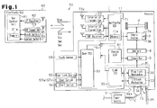
Fig. 1 is a block diagram of a vehicle and an electronic key in a first embodiment; -
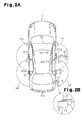
Fig. 2A is a schematic diagram showing a transmission area of a request signal in the first embodiment; -
Fig. 2B is a partially enlarged view ofFig. 2A ; -
Fig. 3 is a flowchart of the processing performed by a controller in the first embodiment; and -
Fig. 4 is a flowchart of the processing performed by a controller in a second embodiment. - A lock device according to a first embodiment of the present invention will now be described with reference to
Figs. 1 to 3 . - Referring to
Fig. 1 , a hybrid electric vehicle 1 performs wireless communication with anelectronic key 80 to permit or perform the locking and unlocking of vehicle doors, the switching to a drivable state, and the activation of the power plug lock device. - In the illustrated example, an
electronic key system 70 includes a wireless key system and a smart system. The wireless key system locks and unlocks the vehicle doors when theelectronic key 80 is manually operated. The smart system locks and unlocks the vehicle doors when bidirectional wireless communication is established between the vehicle 1 and theelectronic key 80. Bidirectional wireless communication is performed automatically and periodically between the vehicle 1 and theelectronic key 80. - The
electronic key 80 will now be described. - The
electronic key 80 includes akey control unit 81, anLF receiver 82, aUHF transmitter 83, alock switch 85, and an unlock switch 86. Thekey control unit 81 includes anon-volatile memory 81 a that stores a key ID code unique to theelectronic key 80. Thekey control unit 81 receives a request signal Sreq, which is transmitted through wireless communication on the low frequency (LF) band, from the vehicle 1 with theLF receiver 82, generates a key ID code signal Sid including the key ID code stored in thememory 81a on the ultrahigh frequency (UHF) band, and transmits through wireless communication the key ID code signal Sid to the vehicle from theUHF transmitter 83. - When pushed by a user, the
lock switch 85 and the unlock switch 86 each provide thekey control unit 81 with an operation signal. Based on the operation signal from thelock switch 85 or the unlock switch 86, thekey control unit 81 determines which one of theswitches 85 and 86 was operated and how it was operated. More specifically, a normal operation, which is a short push of thelock switch 85 or the unlock switch 86, and a special operation, which is a long push of thelock switch 85 or the unlock switch 86, may be performed. A long push is the pushing of theswitch 85 or 86 over a predetermined time or longer. Thekey control unit 81 holds a threshold indicating the predetermined time or a special request signal determination reference value. Each of thelock switch 85 and the unlock switch 86 is an example of a control switch. Further, each of thelock switch 85 and the unlock switch 86 is an example of a switch button. - When the
key control unit 81 determines that the unlock switch 86 has been short-pushed, thekey control unit 81 generates an unlock request signal Sun, which includes the key ID code stored in thememory 81 a. Then, thekey control unit 81 provides the generated unlock request signal Sun to theUHF transmitter 83. TheUHF transmitter 83 transmits through wireless communication the unlock request signal Sun. The unlock request signal Sun may be modulated to a UHF band signal by thekey control unit 81 or theUHF transmitter 83. - When the
key control unit 81 determines that thelock switch 85 has been short-pushed, thekey control unit 81 generates a lock request signal Slo, which includes the key ID code stored in thememory 81 a. Then, thekey control unit 81 transmits through wireless communication the generated lock request signal Slo from theUHF transmitter 83. The lock request signal Slo, may be modulated to a UHF band signal by thekey control unit 81 or theUHF transmitter 83. - When the
key control unit 81 determines that thelock switch 85 or the unlock switch 86 has been long-pushed from an operation signal of thelock switch 85 or the unlock switch 86, thekey control unit 81 generates a special request signal Ssp and transmits the generated special request signal Ssp from theUHF transmitter 83 as a wireless signal on the UHF band. The special request signal Ssp is in correspondence with a special operation performed on thelock switch 85 or the unlock switch 86. - The vehicle 1 will now be described.
- A
controller 11 is installed in the vehicle 1. The controller includes a verification electronic control unit (ECU) 71, acharge ECU 61, abody ECU 51, and alock ECU 35. TheECUs - The vehicle 1 includes a hybrid vehicle power train system (hybrid system) 3, a
battery 4, and a plug lock device 31. Thehybrid system 3 uses the power of an engine 3a and the power of amotor 3b to drive thedrive wheels 2 of the vehicle 1. Thebattery 4 supplies electric power to themotor 3b. The plug lock device 31 locks apower plug 10, which is used to charge thebattery 4. - An
inlet 34 is arranged in a side wall of the vehicle 1 (e.g., behind rear right vehicle door). Apower plug 10 is connected to theinlet 34. Theinlet 34 is arranged in a power port 34a formed in the side wall of the vehicle 1. Alid 36 closes the power port 34a and hides theinlet 34. When thelid 36 is closed, a lid lock mechanism 33 closes thelid 36. When, for example, a lid open lever (not shown) arranged near the driver seat is operated, the lid lock mechanism 33 opens thelid 36. When thelid 36 opens, theinlet 34 is exposed. - When the
lid 36 is open, thepower plug 10 is connectable to theinlet 34. When thepower plug 10 is connected to theinlet 34, theinlet 34 and a converter 6 connects thepower plug 10 to thebattery 4. Acharge cable 12 supplies thepower plug 10 with electric power from an external power supply 91. Accordingly, when thepower plug 10 is connected to theinlet 34, thepower plug 10 can supply the converter 6 with AC power from the external power supply 91 via theinlet 34. The converter 6 converts AC power from thepower plug 10 to DC power and supplies thebattery 4 with DC power. Thecharge ECU 61 controls the converter 6 to charge thebattery 4. - The
body ECU 51 is connected to adoor lock device 55, door switches 57a to 57d, and astart switch 58. - As shown in
Fig. 2A , the door switches 57a to 57d are arranged on outer door handles of the vehicle doors, respectively. When pushed, each of the door switches 57a to 57d provides an operation signal to thebody ECU 51. For example, thedoor switch 57a is arranged on the front right door (driver door), thedoor switch 57b is arranged on the rear right door, thedoor switch 57c is arranged on the front left door, and thedoor switch 57d is arranged on the rear left door. - Referring to
Fig. 1 , thestart switch 58 is arranged in the passenger compartment near the driver seat. When pushed, thestart switch 58 provides an operation signal to thebody ECU 51. - The
verification ECU 71 includes amemory 71 a storing the key ID code of the registeredelectronic key 80. Theverification ECU 71 is connected to anexterior LF transmitter 72, aninterior LF transmitter 73, and aUHF receiver 74. - Referring to
Fig. 2A , theexterior LF transmitter 72 is arranged in each outer door handle to transmit a wireless signal on the LF band to the surrounding of the vehicle 1. - The
interior LF transmitter 73 is arranged in the passenger compartment to transmit a wireless signal on the LF band in the passenger compartment. TheUHF receiver 74 receives and demodulates wireless signals on the UHF band from inside and outside the vehicle 1. - When, for example, the engine is stopped and the vehicle doors are locked, the
verification ECU 71 intermittently transmits a request signal Sreq to the surrounding of the vehicle 1 from eachexterior LF transmitter 72. For example, theexternal LF transmitters 72 on the vehicle doors respectively form exterior communication areas A1 to A4 and transmit request signals Sreq to the corresponding exterior communication areas A1 to A4. In one example, theverification ECU 71 transmits request signals Sreq from theexterior LF transmitters 72 to the exterior communication areas A1 to A4 in a predetermined order. - The
verification ECU 71 receives a key ID code Sid returned from the electronic key 80 in response to the request signal Sreq from theUHF receiver 74. Then, theverification ECU 71 performs ID verification (door lock exterior verification) with the key ID code in the received key ID code signal Sid and the key ID code registered to thememory 71 a. Under a situation in which theverification ECU 71 accomplishes exterior verification, when thebody ECU 51 detects operation of any one of the door switches 57a to 57d, thebody ECU 51 activates thedoor lock device 55 to lock or unlock the vehicle doors. In this manner, the smart system locks and unlocks the vehicle doors. Theverification ECU 71 may recognize in which one of the exterior communication areas A1 to A4 theelectronic key 80 was located when exterior communication was accomplished. - When the
verification ECU 71 receives an unlock request signal Sun through theUHF receiver 74, theverification ECU 71 verifies the ID code in the received unlock request signal Sun with the ID code stored in thememory 71a. Then, when the verification is accomplished, theverification ECU 71 activates thedoor lock device 55 to unlock the vehicle doors. When receiving a lock request signal Slo, theverification ECU 71 performs ID code verification in the same manner. Then, when the verification is accomplished, theverification ECU 71 activates thedoor lock device 55 to lock the vehicle doors. In this manner, the wireless key system locks and unlocks the vehicle doors. - When a vehicle door opens after the exterior verification is accomplished and the vehicle doors are unlocked, the
verification ECU 71 determines that the driver has entered the vehicle 1 and transmits a request signal Sreq from theinterior LF transmitter 73. Theinterior LF transmitter 73 forms an interior communication area B1 about theinterior LF transmitter 73 and transmits the request signal Sreq to the interior communication area B1. - When the
verification ECU 71 receives a key ID code signal Sid from the electronic key 80 through theUHF receiver 74, theverification ECU 71 performs ID verification (interior verification) with the key ID code registered in thememory 71a and the key ID code in the key ID code signal Sid. Under a situation in which interior verification is accomplished, when thestart switch 58 is operated, theverification ECU 71 activates thehybrid system 3 and permits driving of the vehicle 1. - In the example shown in
Figs. 2A and 2B , theinlet 34 is arranged in the rear right side of the vehicle 1, that is, behind the rear right door. The exterior communication area A2 is closest to theinlet 34. - As shown in
Fig. 1 , theinlet 34 includes a plug lock mechanism 32 that locks thepower plug 10 to theinlet 34. Under the control of thecharge ECU 61, thebattery 4 may be charged through thepower plug 10 connected to theinlet 34. - If the door lock exterior verification is accomplished when the
electronic key 80 is located in exterior communication area A2, which is formed near the rear right door and, at the same time, thecontroller 11 detects a special request signal Ssp received with theUHF receiver 74, thecontroller 11 activates the plug lock mechanism 32 and locks or unlocks thepower plug 10. For example, if thepower plug 10 is locked when exterior verification is accomplished, thecontroller 11 unlocks thepower plug 10 in response to the special request signal Ssp. Theunlocked power plug 10 may be removed from theinlet 34. The plug lock device 31 includes thelock ECU 35 and the plug lock mechanism 32. - The detection of the special request signal Ssp is one example of a first condition. The accomplishment of the door lock exterior verification of the electronic key 80 located in the exterior communication area A2 is one example of a second condition. When the first and second conditions are satisfied, the
verification ECU 71 locks or unlocks thepower plug 10. Thepower plug 10 that is connected to theinlet 34 is one example of a locking subject. - The flowchart of
Fig. 3 will now be described. The flowchart briefly illustrates a process performed cooperatively by all or some of theECUs controller 11. In the illustrated example, based on the opening and closing history and present condition of the vehicle doors and the state of the engine, when thecontroller 11 determines that there is a high probability of the user who is carrying the electronic key 80 standing outside the vehicle 1, thecontroller 11 repeats the process ofFig. 3 . Thecontroller 11 also performs in parallel a process related to the locking and unlocking of the vehicle doors. - The
controller 11 checks whether or not theelectronic key 80 is located in the exterior communication area A2 formed near the rear right door, that is, whether or not exterior verification has been accomplished in the exterior communication area A2 (S101). When thecontroller 11 determines that theelectronic key 80 is not located in the exterior communication area A2 (NO in S101), thecontroller 11 ends the process ofFig. 3 without switching the lock state of thepower plug 10. - When the
controller 11 determines that theelectronic key 80 is located in the exterior communication area A2, that is, theelectronic key 80 is located in the exterior communication area A2 (YES in S101), thecontroller 11 determines whether or not a special request signal Ssp has been received (S102). - When the
controller 11 determines that a special request signal Ssp has not been received (NO in S102), thecontroller 11 ends the process ofFig. 3 without switching the lock state of thepower plug 10. When thecontroller 11 determines that a special request signal Ssp has been received (YES in S102), thecontroller 11 switches the lock state of the power plug 10 (S103). - The
controller 11 includes computer-readable instructions to be executed by thecontroller 11. In some embodiments, the instructions may be stored in a computer-readable storage device, such as a magnetic disk or an optical disc, coupled to, accessed by, or included in thecontroller 11. In some embodiments, one or more of theECUs - The first embodiment has the advantages described below.
- (1) By performing long-pushing (special operation) on the
lock switch 85 or the unlock switch 86 of theelectronic key 80, the plug lock device 31, and ultimately thepower plug 10 connected to theinlet 34, are switched between a lock state that restricts connection and removal of thepower plug 10 to and from theinlet 34 and an unlock state that permits connection and removal of thepower plug 10 to and from theinlet 34. This allows the user to use theswitches 85 and 86 of theelectronic key 80, which are for locking an unlocking the vehicle doors, when locking and unlocking thepower plug 10. Since a dedicated switch corresponding to the plug lock mechanism 32 does not have to be arranged in the plug lock device 31, the structure of the plug lock device 31 may be simplified. - (2) Under a situation in which exterior verification is accomplished between the
controller 11 and theelectronic key 80, when a special operation (long-pushing) is performed on thelock switch 85 or the unlock switch 86, thecontroller 11 switches thepower plug 10 between the lock state and the unlock state. For example, when theelectronic key 80, which is held by a user, is separated from the vehicle 1 by a distance at which the smart system cannot establish wireless communication, thepower plug 10 cannot be easily switched between a lock state and an unlock state. This improves the security of the plug lock device 31. - (3) If a special operation is performed on the
switches 85 and 86 of the electronic key 80 when theelectronic key 80 is located in the exterior communication area A2, which is closest to theinlet 34, the plug lock device 31 is switched between a lock state and an unlock state. Accordingly, the special operation allows for the user to easily recognize whether or not the state of the plug lock device 31 has been switched.
In some examples, when theswitches 85 and 86 of the electronic key 80 undergo a special operation in any one of exterior communication areas A1, A3, and A4, which are relatively high from theinlet 34, thecontroller 11 does not permit the plug lock device 31 to switch between a lock state and an unlock state. In this configuration, when the special operation is erroneously performed on theswitches 85 and 86 of the electronic key 80 in the exterior communication areas A1, A3, and A4, which are relatively far from theinlet 34, thepower plug 10 cannot be easily unlocked. This improves the security of the plug lock device 31. - (4) The
exterior LF transmitter 72 that transmits wireless signals of the smart system may be used to transmit a wireless signal for switching the lock state of thepower plug 10. Since there is no need to provide the plug lock device 31 with an LF transmitter, the structure of the plug lock device 31 may be simplified.
A second embodiment of the present invention will now be described focusing on differences from the first embodiment.
In the second embodiment, thecontroller 11 switches the lock state of the power plug in accordance with the flowchart ofFig. 4 .
Thekey control unit 81 of the second embodiment does not determine whether or not a special operation has been performed on thelock switch 85 or the unlock switch 86. Thus, theelectronic key 80 of the second embodiment does not transmit a special request signal Ssp.
Referring toFig. 4 , thecontroller 11 checks the condition of thedoor lock device 55, that is, whether or not the vehicle doors are locked (S201). When determining that the vehicle doors are locked (YES in S201), thecontroller 11 determines whether or not a lock request signal Slo has been received (S202). When determining that the lock request signal Slo has been received (YES in S202), thecontroller 11 switches thepower plug 10 to the lock state (S203) and then ends the process ofFig. 4 .
When determining that the vehicle doors are unlocked (NO in S201), thecontroller 11 determines whether or not an unlock request signal Sun has been received (S204). When determining that an unlock request signal Sun has been received (YES in S204), thecontroller 11 switches thepower plug 10 to the unlock state (S205) and then ends the process ofFig. 4 .
When determining that a lock request signal Slo and an unlock request signal Sun have not been received (NO in S202 and NO in S204), thecontroller 11 ends the process ofFig. 4 without switching the lock state of thepower plug 10.
In the second embodiment, when the vehicle 1 is in a lock state, a short-push of thelock switch 85 corresponds to a special operation. When the vehicle 1 is in an unlock state, a short-push of the unlock switch 86 corresponds to a special operation.
The second embodiment has the advantages described below. - (5) The lock device uses the
lock switch 85, which is not intentionally operated by the user when the vehicle 1 is in a lock state, to switch thepower plug 10 to a lock state. For example, when the vehicle 1 is locked, the user may short-push thelock switch 85 of the electronic key 80 to switch the plug lock device 31 (power plug 10) to a lock state. Further, by using thelock switch 85 to lock thepower plug 10, the lock device may easily be operated by the user. Moreover, the user may successively lock the vehicle doors and lock thepower plug 10. Thus, the lock device may shift to a state allowing for the user to leave the vehicle 1 within a short period of time. - (6) The lock switch uses the unlock switch 86, which is not intentionally operated by the user when the vehicle 1 is in an unlocked state, to switch the
power plug 10 to an unlock state. For example, when the vehicle 1 is unlocked, the user may short-push the unlock switch 86 of the electronic key 80 to switch the plug lock device 31 to an unlock state. Further, by using the unlock switch 86 to unlock thepower plug 10, the lock device may easily be operated by the user. Moreover, the user may successively unlock the vehicle doors and unlock thepower plug 10. Thus, after unlocking thepower plug 10, the user may shift the vehicle 1 to a drivable state within a short period of time by removing thepower plug 10 from theinlet 34. - It should be apparent to those skilled in the art that the present invention may be embodied in many other specific forms without departing from the spirit or scope of the invention. Particularly, it should be understood that the present invention may be embodied in the following forms.
- In the first embodiment, the
controller 11 shifts the lock state of thepower plug 10 when receiving a special request signal Ssp under a situation in which exterior verification is accomplished with the electronic key 80 located in the exterior communication area A2. Instead, the lock state of thepower plug 10 may be switched regardless of whether or not thecontroller 11 accomplishes exterior verification. In this modification, the lock state of thepower plug 10 may be switched from a position that is separated from the vehicle 1. This is convenient. - In the above embodiment, the lock state of the
power plug 10 may be switched in response to a special operation performed on thelock switch 85 or the unlock switch 86. Instead, thecontroller 11 may activate the lid lock mechanism 33 to switch thelid 36 between a lock state and an unlock state in response to the special operation. Thelid 36 cannot be opened when locked and can be opened when unlocked. For example, thelock ECU 35 provides the lid lock mechanism 33 with a drive signal to switch thelid 36 between a lock state and an unlock state. In some embodiments, when the conditions of transponder verification or the like are satisfied, thecontroller 11 activates the lid lock mechanism 33 and switches thelid 36 between closed and open states. In this example, thelid 36 corresponds to a locking subject. - In the first embodiment, the special operation is a long push of the
lock switch 85 or the unlock switch 86. Instead, the special operation may be short pushes performed a number of times on thelock switch 85 or the unlock switch 86. In this case, in the same manner as the first embodiment, thekey control unit 81 may determine whether or not a special operation was performed on the electronic key 80 based on an operation signal from thelock switch 85 or the unlock switch 86. Alternatively, thecontroller 11 may determine whether or not a special operation was performed on theelectronic key 80 by receiving the lock request signal Slo or the unlock request signal Sun for a number of times. Further, thelock switch 85 and the unlock switch 86 may be simultaneously pushed as the special operation. In this case, when thekey control unit 81 simultaneously receives operation signals from thelock switch 85 and the unlock switch 86, thekey control unit 81 may transmit through wireless communication the special request signal Ssp from theUHF transmitter 83. - In the first embodiment, if a special request signal Ssp is detected when door lock exterior verification is accomplished on the electronic key 80 located in the exterior communication area A2 that is closest to the
inlet 34, thepower plug 10 is switched between an unlock state and a lock state. However, the lock states of thepower plug 10 may also be switched when theelectronic keys 80 are located in the other exterior communication areas A1, A3, and A4. - For example, if the controller acknowledges a special request signal Ssp when exterior verification is accomplished on the electronic key 80 located in the exterior communication area that is located near the front right door (driver door), the
controller 11 switches thepower plug 10 to a lock state. In this case, the location where an operation is performed to switch the lock state of the power plug 10 (exterior communication area A1) is close to where a fuel lid lever is located, which is the vicinity of the driver seat, in a conventional vehicle. Thus, a user accustomed to the structure of a conventional vehicle may switch the lock state of thepower plug 10 without being confused. This configuration may be employed especially in vehicles that do not include exterior communication areas A2 and A4 set for the rear doors. - In the above embodiments, among the plurality of exterior communication areas set around the vehicle 1, the exterior communication area A2 is closest to the back door. In the example illustrated in
Fig. 2A , thedoor switch 37e and theexterior LF transmitter 72 may be arranged in a handle of a back door. In this case, thecontroller 11 forms an exterior communication area by transmitting the request signal Sreq to the surrounding of the back door from theexterior LF transmitter 72 of the back door. For example, thepower plug 10 may be stored in the luggage compartment. In this case, the user may open the back door to remove thepower plug 10 from the luggage compartment and then perform a special operation on thelock switch 85 or the unlock switch 86 near the back door to open thelid 36. Thus, the user may smoothly carry out a sequence of tasks from the removal of thepower plug 10 to the connection of thepower plug 10 to theinlet 34. - Referring to the broken lines in
Fig. 1 , in the above embodiments, a touch sensor 59 may be arranged in each door handle. If thecontroller 11 recognizes with a touch sensor 59 that the user has touched a door handle, thecontroller 11 switches the vehicle doors from a lock state to an unlock state. - In the above embodiments, the inlet 34 (including the
lid 36 and the lock mechanisms 32 and 33) is arranged in the right rear side of the vehicle body but may be arranged at other locations, such as the left rear side or front portion of the vehicle body. The one of the exterior communication areas A1 to A4 closest to theinlet 34 differs in accordance with the location of theinlet 34. - In the above embodiments, the user may switch the lock state of the
power plug 10 by performing a special operation on thelock switch 85 or the unlock switch 86 in the exterior communication areas A1 to A4. Instead, the user may switch the lock state of thepower plug 10 by performing a special operation or a normal operation (short push) on thelock switch 85 or the unlock switch 86 in the interior communication area B1. In this case, the location where an operation is performed to switch the lock state of the power plug 10 (interior communication area B1) is close to where a fuel lid lever is located, which is the vicinity of the driver seat, in a conventional vehicle. Thus, a user accustomed to the structure of a conventional vehicle may switch the lock state of thepower plug 10 without being confused. In this configuration, for example, the lock state of thepower plug 10 may be switched by short-pushing thelock switch 85 or the unlock switch 86 in the vehicle 1. The lock state of the vehicle doors is seldom switched when theelectronic key 80 is located in the vehicle 1. Thus, in the vehicle 1, there would be no problem when using thelock switch 85 and the unlock switch 86 to switch the lock state of thepower plug 10. - The lock state of the
power plug 10 may be switched when a special operation is performed on thelock switch 85 or the unlock switch 86 in any one of the exterior communication areas A1 to A4 and the interior communication area B1. - The lock state of the
power plug 10 may be switched by performing a normal operation on thelock switch 85 or the unlock switch 86 in the exterior communication areas A1 to A4. - In the first embodiment, the
power plug 10 may be switched between a lock state and an unlock state by performing a special operation on thelock switch 85 or the unlock switch 86. Instead, a special operation may be performed to switch thepower plug 10 only from a lock state to an unlock state to prohibit switching from an unlock state to a lock state. - In the above embodiment, the control contents of the
ECUs controller 11 may be changed. - In the above embodiment, the
exterior LF transmitter 72 for the smart system is used for communication related to the switching of the lock state of thepower plug 10. However, an LF transmitter dedicated for plug locking may be arranged in the vehicle 1 near theinlet 34. The LF transmitter transmits a request signal Sreq around theinlet 34. Otherwise, the configuration may be the same as the above embodiments. - In the above embodiments, the vehicle 1 may be an electric vehicle instead of a hybrid electric vehicle.
- In the first embodiment, the special operation for switching the
power plug 10 from a lock state to an unlock state and the special operation for switching thepower plug 10 from an unlock state to a lock state are both long-pushes and thus the same. However, the two special operations may differ from each other. For example, the power plug may be switched from a lock state to an unlock state when a control switch is operated by a first predetermined number of times, and the power plug may be switched from an unlock state to a lock state when a control switch is operated by a second predetermined number of times. In this case, thekey control unit 81 holds the first and second predetermined number as special request signal determination reference values. - In the first embodiment, when receiving the special request signal Ssp, the
controller 11 switches the lock state of thepower plug 10. However, thecontroller 11 may determine whether or not exterior verification has been accomplished by periodically transmitting the request signal Sreq from the vehicle after receiving the special request signal Ssp, and then switching the power plug to the lock state when exterior verification is no longer accomplished. - In the first embodiment, the
lock switch 85 and the unlock switch 86 are separately arranged. However, theswitches 85 and 86 may be combined into a lock-unlock switch. In this case, when the lock-unlock switch is short-pushed, the electronic key 80 transmits a lock-unlock request signal. When thecontroller 11 receives and acknowledges the lock-unlock request signal, thecontroller 11 switches the lock-unlock state of the vehicle doors. When the lock-unlock switch undergoes a special operation (e.g., long pushing), the electronic key 80 transmits the special request signal Ssp. - The
key control unit 81 may include the key ID code in the special request signal Ssp when transmitting through wireless communication the special request signal Ssp from theUHF transmitter 83. Thecontroller 11 switches the lock state of thepower plug 10 only when the key ID code in the received special request signal Ssp is verified. Thus, the lock state of thepower plug 10 cannot easily be switched based on a special request signal from a key other than the authentic electronic key 80. - In the second embodiment, step S101 of
Fig. 3 may be performed before step S201 ofFig. 4 . For example, when determining that exterior verification has been accomplished on the electronic key 80 that is located in the exterior communication area A2 (YES in S101), thecontroller 11 processes step S201. When determining that theelectronic key 80 is not located in the exterior communication area A2 (NO in S101), thecontroller 11 ends the processing without switching the lock state of thepower plug 10. The exterior communication area A2 may be replaced by one of the exterior communication areas A1, A3, and A4 and the interior communication area B1. This example has advantage (2) of the first embodiment. - In lieu of or in addition to the
lock switch 85 and the unlock switch 86, thecontroller 11 may switch the lock state of thepower plug 10 in response to a special operation performed on a different control switch, such as a switch manually operated by a user to open and close a slide door. - The above description is intended to be illustrative, and not restrictive. For example, the above-described examples (or one or more aspects thereof) may be used in combination with each other. Inventive subject matter may lie in less than all features of a particular disclosed embodiment and may be modified within the scope and equivalence of the appended claims.
- A lock device is arranged in a vehicle (1) including an inlet (34) used for charging. The vehicle (1) is configured to perform a predetermined control operation in accordance with a control request signal transmitted through wireless communication from an electronic key (80) when a normal operation is performed on a control switch (85; 86) of the electronic key. The lock device includes a lock mechanism (32, 33) configured to switch a locking subject (10; 36) related with the inlet between a lock state and an unlock state. A controller (11) controls the lock mechanism to switch the locking subject between a lock state and an unlock state when detecting a special operation performed on the control switch (85; 86).
Claims (14)
- A lock device to be arranged in a vehicle including an inlet used for charging,
wherein the vehicle is configured to perform a predetermined control operation in accordance with a control request signal transmitted through wireless communication from an electronic key when a normal operation is performed on a control switch of the electronic key, the lock device comprising:a lock mechanism configured to switch a locking subject related with the inlet between a lock state and an unlock state; anda controller that controls the lock mechanism to switch the locking subject between a lock state and an unlock state when detecting a special operation performed on the control switch. - The lock device according to claim 1, wherein
the controller permits the predetermined control operation of the vehicle when the electronic key is verified through wireless communication performed between the vehicle and the electronic key, and
the controller switches the locking subject between the lock state and the unlock state under the condition that the wireless communication and the special operation of the control switch have both been performed. - The lock device according to claim 2, wherein
a plurality of exterior communication areas are formed around the vehicle, and
the wireless communication is performed with the electronic key located in the one of the exterior communication areas that is closest to the inlet. - The lock device according to claim 2, wherein
a plurality of exterior communication areas are formed around the vehicle, and
the wireless communication is performed with the electronic key located in the one of the exterior communication areas that is closest to a driver door. - The lock device according to claim 2, wherein the wireless communication is performed with the electronic key located in an interior communication area formed in the vehicle.
- The lock device according to claim 2, wherein
a plurality of exterior communication areas are formed around the vehicle, and
the wireless communication is performed with the electronic key located in the one of the exterior communication areas that is closet to a back door. - The lock device according to any one of preceding claims, wherein
the control switch includes an unlock switch,
the control request signal includes an unlock request signal transmitted from the electronic key when a normal operation is performed on the unlock switch,
the unlock request signal requests for doors of the vehicle to be unlocked as the predetermined control operation, and
when the vehicle is already unlocked and the controller receives the unlock request signal, the controller determines that the special operation has been performed on the unlock switch of the electronic key and controls the lock mechanism. - The lock device according to any one of preceding claims, wherein
the control switch includes a lock switch operated to lock doors of the vehicle,
the control request signal includes a lock request signal transmitted from the electronic key when a normal operation is performed on the lock switch,
the unlock request signal requests for the doors of the vehicle to be locked as the predetermined control operation, and
when the vehicle is already locked and the controller receives the lock request signal, the controller determines that the special operation has been performed on the lock switch of the electronic key and controls the lock mechanism. - The lock device according to any one of preceding claims, wherein the locking subject includes a power plug connected to the inlet.
- The lock device according to any one of preceding claims, wherein the locking subject includes an inlet lid that hides the inlet.
- The lock device according to any one of preceding claims, wherein the normal operation is a short push, and the special operation is a long push or a plurality of short pushes.
- An electronic key system comprising:an electronic key that transmits through wireless communication a door unlock request signal and a first special request signal; anda controller programmed to control a door lock device and a power plug lock mechanism that are arranged in a vehicle, whereinthe electronic key includes a first switch button and a key control unit, which holds a threshold and is connected to the first switch button,the key control unit is programmed to generate either one of the door unlock request signal and the first special request signal when the first switch button is pushed in accordance with a comparison of the threshold with a pushed period or pushed number of times of the first switch button,the controller is configured to
control the door lock device to unlock doors in accordance with the door unlock request received from the electronic key, and
control the power plug lock mechanism to unlock the power plug in accordance with the first special request signal received from the electronic key. - An electronic key system comprising:an electronic key including a first switch button and a key control unit, which transmits through wireless communication a door unlock request signal when the first switch button is pushed; anda controller programmed to control a door lock device and a power plug lock mechanism that are arranged in a vehicle, wherein the controller is configured to
control the door lock device to unlock doors in accordance with the door unlock request that is received when the doors are locked by the door lock device, and
control the power plug lock mechanism to unlock the power plug in accordance with the door unlock request signal that is received when the doors are unlocked by the door lock device. - The electronic key system according to claim 13, wherein
the electronic key further includes a second switch button connected to the key control unit, the key control unit is programmed to transmit through wireless communication a door lock request signal when the second switch button is pushed, and
the controller is configured to
control the door lock device to lock the doors in accordance with the door lock request that is received when the doors are unlocked by the door lock device, and
control the power plug lock mechanism to lock the power plug in accordance with the door lock request signal that is received when the doors are locked by the door lock device.
Applications Claiming Priority (1)
| Application Number | Priority Date | Filing Date | Title |
|---|---|---|---|
| JP2012272490A JP6068120B2 (en) | 2012-12-13 | 2012-12-13 | Locking device |
Publications (2)
| Publication Number | Publication Date |
|---|---|
| EP2743120A2 true EP2743120A2 (en) | 2014-06-18 |
| EP2743120A3 EP2743120A3 (en) | 2017-06-28 |
Family
ID=49911145
Family Applications (1)
| Application Number | Title | Priority Date | Filing Date |
|---|---|---|---|
| EP13196608.7A Withdrawn EP2743120A3 (en) | 2012-12-13 | 2013-12-11 | Lock device and electronic key system |
Country Status (4)
| Country | Link |
|---|---|
| US (1) | US9495819B2 (en) |
| EP (1) | EP2743120A3 (en) |
| JP (1) | JP6068120B2 (en) |
| CN (1) | CN103872517A (en) |
Cited By (1)
| Publication number | Priority date | Publication date | Assignee | Title |
|---|---|---|---|---|
| FR3142953A1 (en) * | 2022-12-09 | 2024-06-14 | Psa Automobiles Sa | Method for controlling the stopping of the electrical charge of a vehicle depending on the locking state of an opening |
Families Citing this family (26)
| Publication number | Priority date | Publication date | Assignee | Title |
|---|---|---|---|---|
| WO2012176264A1 (en) * | 2011-06-20 | 2012-12-27 | トヨタ自動車株式会社 | Non-contact power reception device, non-contact power transmission device, and non-contact power reception and transmission system |
| JP6068120B2 (en) * | 2012-12-13 | 2017-01-25 | 株式会社東海理化電機製作所 | Locking device |
| JP2014117973A (en) * | 2012-12-13 | 2014-06-30 | Tokai Rika Co Ltd | Lock device |
| CN104157030A (en) * | 2014-06-29 | 2014-11-19 | 深圳市赛亿科技开发有限公司 | Method for controlling door lock through electronic network communication equipment |
| EP3256672B1 (en) * | 2015-02-10 | 2019-11-13 | Dorel France | Access-control fixture lock |
| CN106347250B (en) * | 2015-07-22 | 2019-09-13 | 比亚迪股份有限公司 | Control device and method for automobile charging cover |
| KR101736998B1 (en) * | 2016-02-01 | 2017-05-17 | 현대자동차주식회사 | Electric vehicle charging connector anti-theft method and apparatus |
| US9827950B2 (en) * | 2016-03-14 | 2017-11-28 | Ford Global Technologies, Llc | Locking assembly and method with authenticated unlocking of electric vehicle supply equipment |
| CN106114248B (en) * | 2016-04-28 | 2019-03-26 | 恒大法拉第未来智能汽车(广东)有限公司 | System for unlocking, unlocking method and vehicle |
| CN106157396B (en) * | 2016-04-28 | 2019-08-23 | 法法汽车(中国)有限公司 | Mobile terminal and electron key for unlock |
| CN106515661B (en) * | 2017-01-04 | 2018-12-11 | 北京长安汽车工程技术研究有限责任公司 | A kind of control method and system that pure electric automobile starts without key |
| DE102017203504B4 (en) * | 2017-03-03 | 2026-04-30 | Volkswagen Aktiengesellschaft | Method for unlocking a charging plug in connection with a charging process of an electrically powered vehicle and electrically powered vehicle |
| CN107284256A (en) * | 2017-05-23 | 2017-10-24 | 北京新能源汽车股份有限公司 | Charging gun electronic lock control method and device and electric automobile |
| CN107226066B (en) * | 2017-05-31 | 2019-11-08 | 重庆长安汽车股份有限公司 | A kind of vehicle keyless entry method |
| WO2019041713A1 (en) * | 2017-08-28 | 2019-03-07 | 刘晓霖 | Intelligent socket having locking function and using method thereof |
| CN108537928A (en) * | 2018-04-10 | 2018-09-14 | 武汉联城家科技发展有限公司 | Intelligently lock and its control method and device and computer readable storage medium |
| US10521987B1 (en) * | 2018-06-11 | 2019-12-31 | Ford Global Technologies, Llc | Enhanced electrified vehicle charger security |
| JP7172668B2 (en) * | 2019-02-01 | 2022-11-16 | トヨタ自動車株式会社 | vehicle |
| JP7268566B2 (en) * | 2019-10-09 | 2023-05-08 | トヨタ自動車株式会社 | vehicle |
| CN113370810A (en) * | 2020-03-09 | 2021-09-10 | 广州汽车集团股份有限公司 | Charging gun electronic lock control method and charging gun electronic lock control system |
| US11462066B2 (en) | 2020-10-20 | 2022-10-04 | Honda Motor Co., Ltd. | System and method for locking a charging port to charge an electric vehicle |
| DE102021110138A1 (en) * | 2021-04-21 | 2022-10-27 | Bayerische Motoren Werke Aktiengesellschaft | Vehicle, computer program, method and transceiver circuitry for a vehicle |
| JP7509105B2 (en) * | 2021-09-22 | 2024-07-02 | トヨタ自動車株式会社 | Vehicles and charging systems |
| JP7509743B2 (en) * | 2021-12-28 | 2024-07-02 | 株式会社クボタ | Electric work vehicle |
| CN115100760B (en) * | 2022-05-23 | 2025-08-12 | 浙江小遛信息科技有限公司 | Vehicle unlocking method and device and vehicle |
| FR3141393A1 (en) * | 2022-10-27 | 2024-05-03 | Psa Automobiles Sa | Automated and configurable management of the unlocking of a charging cable connected to a socket of a hybrid or electric motor vehicle |
Family Cites Families (41)
| Publication number | Priority date | Publication date | Assignee | Title |
|---|---|---|---|---|
| US5202617A (en) * | 1991-10-15 | 1993-04-13 | Norvik Technologies Inc. | Charging station for electric vehicles |
| US5413493A (en) | 1993-01-15 | 1995-05-09 | Hubbell Incorporated | Electrical connector assembly, especially for electric vehicle |
| JP4382555B2 (en) | 2004-03-30 | 2009-12-16 | 富士重工業株式会社 | Fuel lid switchgear |
| US8179230B2 (en) * | 2005-12-29 | 2012-05-15 | Renault Trucks | Method for passive keyless entry of a motor vehicle especially of an industrial vehicle |
| JP4379823B2 (en) * | 2007-09-25 | 2009-12-09 | 株式会社デンソー | Vehicle charging system |
| US8022808B2 (en) | 2007-10-01 | 2011-09-20 | Denso International America, Inc. | Vehicle power door control with passive entry |
| CN101821467B (en) | 2007-10-10 | 2015-10-21 | 丰田自动车株式会社 | The control device of vehicle and control method |
| JP2010179694A (en) * | 2009-02-03 | 2010-08-19 | Denso Corp | Plug-in vehicle management system |
| JP2010182239A (en) * | 2009-02-09 | 2010-08-19 | Denso Corp | Plug-in vehicle management system |
| DE102009016504A1 (en) * | 2009-04-08 | 2011-04-21 | Rwe Ag | Charging cable locking device and method for locking a cable |
| JP5029783B2 (en) * | 2009-05-28 | 2012-09-19 | トヨタ自動車株式会社 | Charging system |
| DE102009030092A1 (en) * | 2009-06-22 | 2010-12-30 | Rwe Ag | Charging cable plug for electric vehicles |
| JP5096518B2 (en) * | 2010-05-12 | 2012-12-12 | 株式会社東海理化電機製作所 | Power supply plug lock device |
| JP5486397B2 (en) * | 2010-05-12 | 2014-05-07 | 株式会社東海理化電機製作所 | Power supply plug lock device |
| JP5249284B2 (en) * | 2010-05-12 | 2013-07-31 | 株式会社東海理化電機製作所 | Lock manual release structure of power plug lock device |
| JP5486398B2 (en) * | 2010-05-12 | 2014-05-07 | 株式会社東海理化電機製作所 | Power supply plug lock device |
| JP5411059B2 (en) * | 2010-05-18 | 2014-02-12 | 株式会社東海理化電機製作所 | Charging inlet device |
| JP5443270B2 (en) * | 2010-05-27 | 2014-03-19 | 株式会社東海理化電機製作所 | Plug lock device |
| US8075329B1 (en) * | 2010-06-08 | 2011-12-13 | Ford Global Technologies, Llc | Method and system for preventing disengagement between an electrical plug and a charge port on an electric vehicle |
| DE102010023784B4 (en) | 2010-06-15 | 2013-11-21 | Temtec Fahrzeugtechnik Entwicklungsgesellschaft Mbh | Closure device for an electrical plug-in coupling device arranged on a motor vehicle or a charging station |
| US8514085B2 (en) * | 2010-06-17 | 2013-08-20 | International Business Machines Corporation | Intelligent switching method and apparatus |
| JP5480066B2 (en) | 2010-08-23 | 2014-04-23 | 株式会社東海理化電機製作所 | Plug lock device |
| JP2012080646A (en) * | 2010-09-30 | 2012-04-19 | Tokai Rika Co Ltd | Power feeding plug locking device |
| US20120126747A1 (en) * | 2010-11-19 | 2012-05-24 | Delphi Technologies, Inc. | Battery charger having non-contact electrical switch |
| US8712648B2 (en) * | 2011-03-08 | 2014-04-29 | Gm Global Technology Operations | Passive charge cord release system for an electric vehicle |
| JP5629616B2 (en) * | 2011-03-18 | 2014-11-26 | 株式会社東海理化電機製作所 | Power supply plug lock device |
| JP2012212647A (en) * | 2011-03-18 | 2012-11-01 | Tokai Rika Co Ltd | Power supply plug lock device |
| JP5635437B2 (en) * | 2011-03-18 | 2014-12-03 | 株式会社東海理化電機製作所 | Power supply plug lock device |
| JP2012226911A (en) * | 2011-04-18 | 2012-11-15 | Tokai Rika Co Ltd | Power feeding plug locking device |
| US8265816B1 (en) * | 2011-05-27 | 2012-09-11 | General Electric Company | Apparatus and methods to disable an electric vehicle |
| US8690591B2 (en) * | 2011-06-09 | 2014-04-08 | GM Global Technology Operations LLC | Electric vehicle with secondary charge cord release mechanism |
| JP5658103B2 (en) * | 2011-07-12 | 2015-01-21 | 株式会社東海理化電機製作所 | Power plug lock device |
| DE102011052078A1 (en) * | 2011-07-22 | 2013-01-24 | Dr. Ing. H.C. F. Porsche Aktiengesellschaft | Charge coupling and charging coupling arrangement for a motor vehicle and motor vehicle |
| US8550833B2 (en) * | 2011-10-07 | 2013-10-08 | Ford Global Technologies, Llc | Locking apparatus for electric vehicle charging connector |
| US8936482B2 (en) * | 2011-11-30 | 2015-01-20 | GM Global Technology Operations LLC | High voltage safety lock sensing—single sensor linear actuator |
| JP5775474B2 (en) * | 2012-02-24 | 2015-09-09 | 株式会社東海理化電機製作所 | Plug lock device |
| JP2014021710A (en) * | 2012-07-18 | 2014-02-03 | Tokai Rika Co Ltd | Lock device |
| JP2014117973A (en) * | 2012-12-13 | 2014-06-30 | Tokai Rika Co Ltd | Lock device |
| JP6068120B2 (en) * | 2012-12-13 | 2017-01-25 | 株式会社東海理化電機製作所 | Locking device |
| JP2014124027A (en) * | 2012-12-20 | 2014-07-03 | Tokai Rika Co Ltd | Plug lock device |
| JP2014135870A (en) * | 2013-01-11 | 2014-07-24 | Tokai Rika Co Ltd | In-vehicle system |
-
2012
- 2012-12-13 JP JP2012272490A patent/JP6068120B2/en active Active
-
2013
- 2013-11-21 US US14/086,097 patent/US9495819B2/en not_active Expired - Fee Related
- 2013-12-05 CN CN201310654918.3A patent/CN103872517A/en active Pending
- 2013-12-11 EP EP13196608.7A patent/EP2743120A3/en not_active Withdrawn
Cited By (1)
| Publication number | Priority date | Publication date | Assignee | Title |
|---|---|---|---|---|
| FR3142953A1 (en) * | 2022-12-09 | 2024-06-14 | Psa Automobiles Sa | Method for controlling the stopping of the electrical charge of a vehicle depending on the locking state of an opening |
Also Published As
| Publication number | Publication date |
|---|---|
| US9495819B2 (en) | 2016-11-15 |
| EP2743120A3 (en) | 2017-06-28 |
| US20140167913A1 (en) | 2014-06-19 |
| JP6068120B2 (en) | 2017-01-25 |
| JP2014117972A (en) | 2014-06-30 |
| CN103872517A (en) | 2014-06-18 |
Similar Documents
| Publication | Publication Date | Title |
|---|---|---|
| US9495819B2 (en) | Lock device and electronic key system for use with vehicle charging inlet | |
| EP2743119A2 (en) | Lock device, lock device controller, and electronic key system | |
| US8239103B2 (en) | Vehicle control device and control method | |
| US7795841B2 (en) | Charging system including user proximity detection to start or stop charging | |
| JP5658103B2 (en) | Power plug lock device | |
| US8089343B2 (en) | Smart entry system | |
| US20140179141A1 (en) | Plug lock device | |
| JP5548090B2 (en) | Power supply plug lock device | |
| US20140022053A1 (en) | Lock device | |
| US20140167915A1 (en) | Lock device, lock device controller, and electric key system | |
| US9377764B2 (en) | Plug lock device | |
| JP5660022B2 (en) | Charging cable lock control system, in-vehicle device, and power supply device | |
| JP2009073432A (en) | Vehicle fuel filler opening / closing mechanism | |
| US20140165676A1 (en) | Lock device, controller, and electric key system | |
| US10759291B2 (en) | System and a method for unlocking a charging plug inserted in a vehicle charging socket | |
| US20140159857A1 (en) | Lock controller and electronic key system for vehicle | |
| US20090058597A1 (en) | Vehicle communication system | |
| JP5169685B2 (en) | Smart entry system | |
| JP6139371B2 (en) | Electronic key system | |
| JP5168052B2 (en) | Smart entry system | |
| JP2010077887A (en) | Engine start control system | |
| KR20120105946A (en) | Dual security key system for vehicle and method for controlling the same | |
| JP6558263B2 (en) | Lid lock device | |
| JP2011259676A (en) | System for preventing plug from being left forgotten to be removed | |
| JP4732245B2 (en) | Vehicle luggage door control system |
Legal Events
| Date | Code | Title | Description |
|---|---|---|---|
| PUAI | Public reference made under article 153(3) epc to a published international application that has entered the european phase |
Free format text: ORIGINAL CODE: 0009012 |
|
| 17P | Request for examination filed |
Effective date: 20131211 |
|
| AK | Designated contracting states |
Kind code of ref document: A2 Designated state(s): AL AT BE BG CH CY CZ DE DK EE ES FI FR GB GR HR HU IE IS IT LI LT LU LV MC MK MT NL NO PL PT RO RS SE SI SK SM TR |
|
| AX | Request for extension of the european patent |
Extension state: BA ME |
|
| PUAL | Search report despatched |
Free format text: ORIGINAL CODE: 0009013 |
|
| AK | Designated contracting states |
Kind code of ref document: A3 Designated state(s): AL AT BE BG CH CY CZ DE DK EE ES FI FR GB GR HR HU IE IS IT LI LT LU LV MC MK MT NL NO PL PT RO RS SE SI SK SM TR |
|
| AX | Request for extension of the european patent |
Extension state: BA ME |
|
| RIC1 | Information provided on ipc code assigned before grant |
Ipc: B60L 11/18 20060101AFI20170523BHEP Ipc: G07C 9/00 20060101ALI20170523BHEP |
|
| STAA | Information on the status of an ep patent application or granted ep patent |
Free format text: STATUS: THE APPLICATION IS DEEMED TO BE WITHDRAWN |
|
| 18D | Application deemed to be withdrawn |
Effective date: 20180103 |