EP2743114A2 - Hybrid driving apparatus - Google Patents
Hybrid driving apparatus Download PDFInfo
- Publication number
- EP2743114A2 EP2743114A2 EP13197138.4A EP13197138A EP2743114A2 EP 2743114 A2 EP2743114 A2 EP 2743114A2 EP 13197138 A EP13197138 A EP 13197138A EP 2743114 A2 EP2743114 A2 EP 2743114A2
- Authority
- EP
- European Patent Office
- Prior art keywords
- clutch
- state
- rust formation
- rotation speed
- rust
- Prior art date
- Legal status (The legal status is an assumption and is not a legal conclusion. Google has not performed a legal analysis and makes no representation as to the accuracy of the status listed.)
- Withdrawn
Links
Images


Classifications
-
- B—PERFORMING OPERATIONS; TRANSPORTING
- B60—VEHICLES IN GENERAL
- B60K—ARRANGEMENT OR MOUNTING OF PROPULSION UNITS OR OF TRANSMISSIONS IN VEHICLES; ARRANGEMENT OR MOUNTING OF PLURAL DIVERSE PRIME-MOVERS IN VEHICLES; AUXILIARY DRIVES FOR VEHICLES; INSTRUMENTATION OR DASHBOARDS FOR VEHICLES; ARRANGEMENTS IN CONNECTION WITH COOLING, AIR INTAKE, GAS EXHAUST OR FUEL SUPPLY OF PROPULSION UNITS IN VEHICLES
- B60K6/00—Arrangement or mounting of plural diverse prime-movers for mutual or common propulsion, e.g. hybrid propulsion systems comprising electric motors and internal combustion engines ; Control systems therefor, i.e. systems controlling two or more prime movers, or controlling one of these prime movers and any of the transmission, drive or drive units Informative references: mechanical gearings with secondary electric drive F16H3/72; arrangements for handling mechanical energy structurally associated with the dynamo-electric machine H02K7/00; machines comprising structurally interrelated motor and generator parts H02K51/00; dynamo-electric machines not otherwise provided for in H02K see H02K99/00
- B60K6/20—Arrangement or mounting of plural diverse prime-movers for mutual or common propulsion, e.g. hybrid propulsion systems comprising electric motors and internal combustion engines ; Control systems therefor, i.e. systems controlling two or more prime movers, or controlling one of these prime movers and any of the transmission, drive or drive units Informative references: mechanical gearings with secondary electric drive F16H3/72; arrangements for handling mechanical energy structurally associated with the dynamo-electric machine H02K7/00; machines comprising structurally interrelated motor and generator parts H02K51/00; dynamo-electric machines not otherwise provided for in H02K see H02K99/00 the prime-movers consisting of electric motors and internal combustion engines, e.g. HEVs
- B60K6/42—Arrangement or mounting of plural diverse prime-movers for mutual or common propulsion, e.g. hybrid propulsion systems comprising electric motors and internal combustion engines ; Control systems therefor, i.e. systems controlling two or more prime movers, or controlling one of these prime movers and any of the transmission, drive or drive units Informative references: mechanical gearings with secondary electric drive F16H3/72; arrangements for handling mechanical energy structurally associated with the dynamo-electric machine H02K7/00; machines comprising structurally interrelated motor and generator parts H02K51/00; dynamo-electric machines not otherwise provided for in H02K see H02K99/00 the prime-movers consisting of electric motors and internal combustion engines, e.g. HEVs characterised by the architecture of the hybrid electric vehicle
- B60K6/44—Series-parallel type
- B60K6/445—Differential gearing distribution type
-
- B—PERFORMING OPERATIONS; TRANSPORTING
- B60—VEHICLES IN GENERAL
- B60K—ARRANGEMENT OR MOUNTING OF PROPULSION UNITS OR OF TRANSMISSIONS IN VEHICLES; ARRANGEMENT OR MOUNTING OF PLURAL DIVERSE PRIME-MOVERS IN VEHICLES; AUXILIARY DRIVES FOR VEHICLES; INSTRUMENTATION OR DASHBOARDS FOR VEHICLES; ARRANGEMENTS IN CONNECTION WITH COOLING, AIR INTAKE, GAS EXHAUST OR FUEL SUPPLY OF PROPULSION UNITS IN VEHICLES
- B60K6/00—Arrangement or mounting of plural diverse prime-movers for mutual or common propulsion, e.g. hybrid propulsion systems comprising electric motors and internal combustion engines ; Control systems therefor, i.e. systems controlling two or more prime movers, or controlling one of these prime movers and any of the transmission, drive or drive units Informative references: mechanical gearings with secondary electric drive F16H3/72; arrangements for handling mechanical energy structurally associated with the dynamo-electric machine H02K7/00; machines comprising structurally interrelated motor and generator parts H02K51/00; dynamo-electric machines not otherwise provided for in H02K see H02K99/00
- B60K6/20—Arrangement or mounting of plural diverse prime-movers for mutual or common propulsion, e.g. hybrid propulsion systems comprising electric motors and internal combustion engines ; Control systems therefor, i.e. systems controlling two or more prime movers, or controlling one of these prime movers and any of the transmission, drive or drive units Informative references: mechanical gearings with secondary electric drive F16H3/72; arrangements for handling mechanical energy structurally associated with the dynamo-electric machine H02K7/00; machines comprising structurally interrelated motor and generator parts H02K51/00; dynamo-electric machines not otherwise provided for in H02K see H02K99/00 the prime-movers consisting of electric motors and internal combustion engines, e.g. HEVs
- B60K6/42—Arrangement or mounting of plural diverse prime-movers for mutual or common propulsion, e.g. hybrid propulsion systems comprising electric motors and internal combustion engines ; Control systems therefor, i.e. systems controlling two or more prime movers, or controlling one of these prime movers and any of the transmission, drive or drive units Informative references: mechanical gearings with secondary electric drive F16H3/72; arrangements for handling mechanical energy structurally associated with the dynamo-electric machine H02K7/00; machines comprising structurally interrelated motor and generator parts H02K51/00; dynamo-electric machines not otherwise provided for in H02K see H02K99/00 the prime-movers consisting of electric motors and internal combustion engines, e.g. HEVs characterised by the architecture of the hybrid electric vehicle
-
- B—PERFORMING OPERATIONS; TRANSPORTING
- B60—VEHICLES IN GENERAL
- B60W—CONJOINT CONTROL OF VEHICLE SUB-UNITS OF DIFFERENT TYPE OR DIFFERENT FUNCTION; CONTROL SYSTEMS SPECIALLY ADAPTED FOR HYBRID VEHICLES; ROAD VEHICLE DRIVE CONTROL SYSTEMS FOR PURPOSES NOT RELATED TO THE CONTROL OF A PARTICULAR SUB-UNIT
- B60W10/00—Conjoint control of vehicle sub-units of different type or different function
- B60W10/02—Conjoint control of vehicle sub-units of different type or different function including control of driveline clutches
-
- B—PERFORMING OPERATIONS; TRANSPORTING
- B60—VEHICLES IN GENERAL
- B60W—CONJOINT CONTROL OF VEHICLE SUB-UNITS OF DIFFERENT TYPE OR DIFFERENT FUNCTION; CONTROL SYSTEMS SPECIALLY ADAPTED FOR HYBRID VEHICLES; ROAD VEHICLE DRIVE CONTROL SYSTEMS FOR PURPOSES NOT RELATED TO THE CONTROL OF A PARTICULAR SUB-UNIT
- B60W20/00—Control systems specially adapted for hybrid vehicles
- B60W20/10—Controlling the power contribution of each of the prime movers to meet required power demand
- B60W20/15—Control strategies specially adapted for achieving a particular effect
-
- F—MECHANICAL ENGINEERING; LIGHTING; HEATING; WEAPONS; BLASTING
- F16—ENGINEERING ELEMENTS AND UNITS; GENERAL MEASURES FOR PRODUCING AND MAINTAINING EFFECTIVE FUNCTIONING OF MACHINES OR INSTALLATIONS; THERMAL INSULATION IN GENERAL
- F16D—COUPLINGS FOR TRANSMITTING ROTATION; CLUTCHES; BRAKES
- F16D48/00—External control of clutches
- F16D48/06—Control by electric or electronic means, e.g. of fluid pressure
-
- B—PERFORMING OPERATIONS; TRANSPORTING
- B60—VEHICLES IN GENERAL
- B60W—CONJOINT CONTROL OF VEHICLE SUB-UNITS OF DIFFERENT TYPE OR DIFFERENT FUNCTION; CONTROL SYSTEMS SPECIALLY ADAPTED FOR HYBRID VEHICLES; ROAD VEHICLE DRIVE CONTROL SYSTEMS FOR PURPOSES NOT RELATED TO THE CONTROL OF A PARTICULAR SUB-UNIT
- B60W2555/00—Input parameters relating to exterior conditions, not covered by groups B60W2552/00, B60W2554/00
- B60W2555/20—Ambient conditions, e.g. wind or rain
-
- B—PERFORMING OPERATIONS; TRANSPORTING
- B60—VEHICLES IN GENERAL
- B60W—CONJOINT CONTROL OF VEHICLE SUB-UNITS OF DIFFERENT TYPE OR DIFFERENT FUNCTION; CONTROL SYSTEMS SPECIALLY ADAPTED FOR HYBRID VEHICLES; ROAD VEHICLE DRIVE CONTROL SYSTEMS FOR PURPOSES NOT RELATED TO THE CONTROL OF A PARTICULAR SUB-UNIT
- B60W2556/00—Input parameters relating to data
- B60W2556/45—External transmission of data to or from the vehicle
- B60W2556/50—External transmission of data to or from the vehicle for navigation systems
-
- F—MECHANICAL ENGINEERING; LIGHTING; HEATING; WEAPONS; BLASTING
- F16—ENGINEERING ELEMENTS AND UNITS; GENERAL MEASURES FOR PRODUCING AND MAINTAINING EFFECTIVE FUNCTIONING OF MACHINES OR INSTALLATIONS; THERMAL INSULATION IN GENERAL
- F16D—COUPLINGS FOR TRANSMITTING ROTATION; CLUTCHES; BRAKES
- F16D2500/00—External control of clutches by electric or electronic means
- F16D2500/30—Signal inputs
- F16D2500/306—Signal inputs from the engine
- F16D2500/3067—Speed of the engine
-
- F—MECHANICAL ENGINEERING; LIGHTING; HEATING; WEAPONS; BLASTING
- F16—ENGINEERING ELEMENTS AND UNITS; GENERAL MEASURES FOR PRODUCING AND MAINTAINING EFFECTIVE FUNCTIONING OF MACHINES OR INSTALLATIONS; THERMAL INSULATION IN GENERAL
- F16D—COUPLINGS FOR TRANSMITTING ROTATION; CLUTCHES; BRAKES
- F16D2500/00—External control of clutches by electric or electronic means
- F16D2500/30—Signal inputs
- F16D2500/312—External to the vehicle
- F16D2500/3121—Ambient conditions, e.g. air humidity, air temperature, ambient pressure
-
- F—MECHANICAL ENGINEERING; LIGHTING; HEATING; WEAPONS; BLASTING
- F16—ENGINEERING ELEMENTS AND UNITS; GENERAL MEASURES FOR PRODUCING AND MAINTAINING EFFECTIVE FUNCTIONING OF MACHINES OR INSTALLATIONS; THERMAL INSULATION IN GENERAL
- F16D—COUPLINGS FOR TRANSMITTING ROTATION; CLUTCHES; BRAKES
- F16D2500/00—External control of clutches by electric or electronic means
- F16D2500/30—Signal inputs
- F16D2500/316—Other signal inputs not covered by the groups above
- F16D2500/3168—Temperature detection of any component of the control system
-
- F—MECHANICAL ENGINEERING; LIGHTING; HEATING; WEAPONS; BLASTING
- F16—ENGINEERING ELEMENTS AND UNITS; GENERAL MEASURES FOR PRODUCING AND MAINTAINING EFFECTIVE FUNCTIONING OF MACHINES OR INSTALLATIONS; THERMAL INSULATION IN GENERAL
- F16D—COUPLINGS FOR TRANSMITTING ROTATION; CLUTCHES; BRAKES
- F16D2500/00—External control of clutches by electric or electronic means
- F16D2500/50—Problem to be solved by the control system
- F16D2500/51—Relating safety
- F16D2500/5102—Detecting abnormal operation, e.g. unwanted slip or excessive temperature
-
- F—MECHANICAL ENGINEERING; LIGHTING; HEATING; WEAPONS; BLASTING
- F16—ENGINEERING ELEMENTS AND UNITS; GENERAL MEASURES FOR PRODUCING AND MAINTAINING EFFECTIVE FUNCTIONING OF MACHINES OR INSTALLATIONS; THERMAL INSULATION IN GENERAL
- F16D—COUPLINGS FOR TRANSMITTING ROTATION; CLUTCHES; BRAKES
- F16D2500/00—External control of clutches by electric or electronic means
- F16D2500/50—Problem to be solved by the control system
- F16D2500/51—Relating safety
- F16D2500/5104—Preventing failures
-
- F—MECHANICAL ENGINEERING; LIGHTING; HEATING; WEAPONS; BLASTING
- F16—ENGINEERING ELEMENTS AND UNITS; GENERAL MEASURES FOR PRODUCING AND MAINTAINING EFFECTIVE FUNCTIONING OF MACHINES OR INSTALLATIONS; THERMAL INSULATION IN GENERAL
- F16D—COUPLINGS FOR TRANSMITTING ROTATION; CLUTCHES; BRAKES
- F16D2500/00—External control of clutches by electric or electronic means
- F16D2500/70—Details about the implementation of the control system
- F16D2500/704—Output parameters from the control unit; Target parameters to be controlled
- F16D2500/70402—Actuator parameters
- F16D2500/7041—Position
-
- Y—GENERAL TAGGING OF NEW TECHNOLOGICAL DEVELOPMENTS; GENERAL TAGGING OF CROSS-SECTIONAL TECHNOLOGIES SPANNING OVER SEVERAL SECTIONS OF THE IPC; TECHNICAL SUBJECTS COVERED BY FORMER USPC CROSS-REFERENCE ART COLLECTIONS [XRACs] AND DIGESTS
- Y02—TECHNOLOGIES OR APPLICATIONS FOR MITIGATION OR ADAPTATION AGAINST CLIMATE CHANGE
- Y02T—CLIMATE CHANGE MITIGATION TECHNOLOGIES RELATED TO TRANSPORTATION
- Y02T10/00—Road transport of goods or passengers
- Y02T10/60—Other road transportation technologies with climate change mitigation effect
- Y02T10/62—Hybrid vehicles
-
- Y—GENERAL TAGGING OF NEW TECHNOLOGICAL DEVELOPMENTS; GENERAL TAGGING OF CROSS-SECTIONAL TECHNOLOGIES SPANNING OVER SEVERAL SECTIONS OF THE IPC; TECHNICAL SUBJECTS COVERED BY FORMER USPC CROSS-REFERENCE ART COLLECTIONS [XRACs] AND DIGESTS
- Y10—TECHNICAL SUBJECTS COVERED BY FORMER USPC
- Y10S—TECHNICAL SUBJECTS COVERED BY FORMER USPC CROSS-REFERENCE ART COLLECTIONS [XRACs] AND DIGESTS
- Y10S903/00—Hybrid electric vehicles, HEVS
- Y10S903/902—Prime movers comprising electrical and internal combustion motors
- Y10S903/903—Prime movers comprising electrical and internal combustion motors having energy storing means, e.g. battery, capacitor
- Y10S903/904—Component specially adapted for hev
- Y10S903/912—Drive line clutch
Definitions
- This disclosure relates to a hybrid driving apparatus which has a clutch that disengageably connects an output shaft of an engine and an input shaft that rotates in association with driving wheels, and a motor generator that rotates in association with rotation of the input shaft.
- Japanese Patent Application Laid-Open No. 2010-76678 discloses a hybrid vehicle having an engine, a clutch that disengageably engages an output shaft of the engine and an input shaft of a gear mechanism, and a motor generator that rotates in association with rotation of the input shaft.
- a hybrid vehicle disclosed in Japanese Patent Application Laid-Open No. 2010-76678 during an electric traveling mode in which the hybrid vehicle travels by a driving force of a motor generator, a clutch is disconnected, so that an engine and a driving wheel are disconnected, so that a friction loss according to rotation of the engine is reduced to improve in fuel efficiency. Meanwhile, during split traveling in which the hybrid travels by the driving forces of the engine and the motor generator, the clutch is connected.
- this hybrid vehicle in order to suppress a loss according to a drag of a clutch during clutch disconnection, it is general to use a dry-type clutch.
- this dry-type clutch in order to suppress overheating of a clutch plate, traveling air is introduced into the clutch, so that the clutch plate is cooled.
- This disclosure was made in view of these circumstances, and this disclosure provides a technology, capable of suppressing rusting of a clutch in a hybrid driving apparatus including the clutch that disengageably connects an output shaft of an engine and an input shaft which rotates in association with driving wheels, and a motor generator that rotates in association with rotation of the input shaft.
- a hybrid driving apparatus of this disclosure includes: an engine configured to output a rotation driving force to an output shaft; an input shaft configured to rotate in association with rotation of driving wheels of a vehicle; a clutch that is provided between the output shaft and the input shaft to disengageably connect the output shaft and the input shaft; a clutch actuator configured to operate the clutch; a motor generator configured to rotate in association with rotation of the input shaft; a rust formation determining unit configured to determine whether there is a possibility of a rust formation on the clutch; and a rust formation suppressing unit configured to operate the clutch actuator in a case where the rust formation determining unit determines that there is the possibility of the rust formation on the clutch.
- the rust formation suppressing unit operates the clutch actuator.
- the clutch transitions from a connected state to a disconnected state, or the clutch transitions from the disconnected state to the connected state. Therefore, it is possible to suppress rusting of the clutch according to continuous connection of the clutch. Also, in a case where the clutch is maintained in the disconnected state, the clutch is connected so that the rust formed on the clutch is removed.
- the rust formation suppressing unit may operate the clutch actuator to operate the clutch in a disconnection direction.
- the rust formation suppressing unit operates the clutch actuator, so that the clutch is disconnected. Therefore, rusting of the clutch due to continuous connection of the clutch is suppressed by the operation of the clutch in the disconnection direction.
- the rust formation suppressing unit may operate the clutch actuator to operate the clutch in a connection direction.
- the rust formation suppressing unit operates the clutch actuator, thereby operating the clutch in the connection direction. Therefore, even if the clutch is disconnected and the sliding surface of the clutch comes into contact with air, so that rust is formed on the sliding surface of the clutch, the clutch is operated in the connection direction so that the sliding surface of the clutch is rubbed, so that it is possible to remove the rust formed on the sliding surface of the clutch. For this reason, in a case where the disconnected clutch is connected again, it is possible to suppress rusting of the clutch and a change in the characteristics of the clutch due to the rust formed on the sliding surface of the clutch.
- the rust formation suppressing unit may operate the clutch actuator to put the clutch into the disconnected state.
- the rust formation suppressing unit operates the clutch actuator, so that the clutch is disconnected. Therefore, if the vehicle becomes the state capable of traveling, the clutch is disconnected, and thus it is possible to suppress rusting of the clutch due to continuous connection of the clutch and to suppress the clutch from becoming incapable of being disconnected.
- the rust formation suppressing unit may operate the clutch actuator to put the clutch into the disconnected state and then put the vehicle into the state incapable of traveling.
- the rust formation suppressing unit operates the clutch actuator to put the clutch into the disconnected state and then puts the vehicle into the state incapable of traveling. Therefore, since the clutch is in the disconnected state during a stop of the vehicle, it is possible to suppress the clutch from becoming incapable of being disconnected due to rusting of the clutch when the vehicle becomes the state capable of traveling again.
- the above-described hybrid driving apparatus may include a rust information acquiring unit that acquires rust information relating to the rust formation on the clutch, wherein based on the rust information, the rust formation determining unit may determine whether there is a possibility of the rust formation on the clutch.
- the rust formation determining unit determines whether there is a possibility of the rust formation on the clutch, based on the rust information. Therefore, it is possible to more reliably determine the possibility of the rust formation on the clutch. For this reason, in a case where there is a possibility of the rust formation on the clutch, the rust formation suppressing unit operates the clutch actuator, thereby capable of suppressing the rust formation on the clutch in advance.
- the rust information acquiring unit may acquire the rust information from an outside of the vehicle.
- the rust information acquiring unit acquires the rust information from the outside of the vehicle. Therefore, for example, based on the location information of the vehicle or the weather information which is the rust information acquired from the outside, it is determined whether there is a possibility of the rust formation on the clutch. Therefore, it is possible to more reliably determine the possibility of the rust formation on the clutch.
- the rust formation suppressing unit operates the clutch actuator to put the clutch into a half-clutch state.
- the rust formation suppressing unit operates the clutch actuator to put the clutch into the half-clutch state. In this way, it is possible to heat the clutch. In a case where water is introduced to the clutch, it is possible to dry the clutch, thereby removing the water. Therefore, it is possible to suppress the rust formation on the clutch in advance. Also, even in a case where rust is formed on a component of the clutch, the clutch is put into the half-clutch state, so that the component of the clutch is rubbed. Therefore, it is possible to remove the rust formed on the above-described component.
- the rust formation suppressing unit may operate the clutch actuator so that the clutch torque of the clutch becomes a target clutch torque to put the clutch into the half-clutch state, and wherein in a case where the clutch differential rotation speed is equal to or higher than the first rotation speed, the rust formation suppressing unit may operate the clutch actuator to put the clutch into the connected state.
- the rust formation suppressing unit operates the clutch actuator so that the clutch torque becomes the target clutch torque to put the clutch into the half-clutch state.
- the clutch torque is controlled so as to be the target clutch torque. Therefore, it is possible to reliably maintain the clutch in the half-clutch state, and to reliably heat the clutch. For this reason, it is possible to dry the clutch, thereby reliably removing water onto the clutch, and even in a case where water is introduced to a component of the clutch, it is possible to reliably remove the water.
- the rust formation suppressing unit operates the clutch actuator to put the clutch into the connected state. Therefore, the clutch is suppressed from becoming the half-clutch state in a state where the clutch differential rotation speed is excessively high. For this reason, overheating of the clutch is suppressed, and it is possible to suppress a decrease in the life of the clutch, and deterioration in the characteristics of the clutch. Also, it is possible to suppress a feeling of deceleration according to a deficiency in transmitting the driving force from the engine, and a decrease in the power generation amount of the motor generator, due to excessive increasing of the clutch differential rotation speed.
- the rust formation suppressing unit may decrease the target clutch torque.
- the rust formation suppressing unit reduces the target clutch torque.
- the clutch differential rotation speed increases. Therefore, it is possible to reliably heat the clutch, and it is possible to dry the clutch, thereby reliably removing water onto the clutch.
- the rust formation suppressing unit may operate the clutch actuator to put the clutch into a half-clutch state.
- the rust formation suppressing unit operates the clutch actuator to put the clutch into the half-clutch state. In this way, it is possible to heat the clutch. In a case where water is introduced to the clutch, it is possible to dry the clutch, thereby removing the water. Therefore, it is possible to suppress the rust formation on the clutch in advance. Also, even in a case where rust is formed on a component of the clutch, the clutch is put into the half-clutch state, so that the component of the clutch is rubbed. Therefore, it is possible to remove the rust formed on the above-described component.
- the rust formation suppressing unit may operate the clutch actuator to put the clutch into the disconnected state.
- the rust formation suppressing unit operates the clutch actuator to put the clutch into the disconnected state.
- the clutch is suppressed from becoming the half-clutch state in a state where the clutch differential rotation speed is excessively high. Therefore, the clutch differential rotation speed is suppressed from excessively increasing, resulting in a rapid rise in the temperature of the clutch and overheating of the clutch, and it is possible to suppress a decrease in the life of the clutch and deterioration in the characteristics of the clutch.
- the rust formation suppressing unit may operate the clutch actuator to put the clutch into the disconnected state.
- the rust formation suppressing unit operates the clutch actuator to put the clutch into the disconnected state. In this way, it is possible to suppress a variation in the friction coefficient of the inside of the clutch from excessively increasing due to the clutch differential rotation speed which is excessively low, i.e. lower than the fourth rotation speed, so that it becomes impossible to heat the clutch as aimed.
- the rust formation suppressing unit may changes a phase of the clutch after disconnecting the clutch and then, and then the rust formation suppressing unit controls the clutch to be connected.
- the rust formation suppressing unit changes the phase of the clutch, and then connects the clutch. In this way, it is possible to suppress sticking of the clutch due to connecting of components of the clutch at the same positions.
- the above-described hybrid driving apparatus may includes a clutch temperature acquiring unit configured to acquire a current temperature of the clutch, in a case where the temperature of the clutch is equal to or higher than a defined temperature, the rust formation suppressing unit may not operate the clutch actuator.
- the rust formation suppressing unit does not operate the clutch actuator. Therefore, the clutch is suppressed from becoming the half-clutch state in a state where the temperature of the clutch is equal to or higher than the defined temperature. For this reason, in a case where the temperature of the clutch reaches a temperature sufficient to dry the clutch, unnecessary heating of the clutch is not performed, and it is possible to suppress a decrease in the power generation amount and a loss of the driving energy of the motor generator. Also, overheating of the clutch is suppressed, and it is possible to suppress a decrease in the life of the clutch, and deterioration of the clutch.
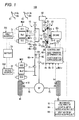
- a hybrid driving apparatus 100 of an embodiment (first embodiment) of this disclosure will be described with reference to the accompanying drawings.
- broken lines represent transmission paths of a variety of information, and alternate long and short dash lines represent transmission paths of electric power.
- a hybrid vehicle (hereinafter, referred to simply as a vehicle) has the hybrid driving apparatus 100.
- the hybrid driving apparatus 100 of the present embodiment includes an engine EG, a first motor generator MG1, a second motor generator MG2, a planetary gear mechanism 10, a clutch 20, a first inverter 31, a second inverter 32, a battery 33, a clutch actuator 50, a control unit 40, and an information acquiring unit 90.
- the state of the clutch 20 until the clutch 20 being in a disconnected state becomes a connected state that is, the state of the clutch 20 in which there is a clutch differential rotation speed ⁇ r is referred to as a half-clutch state or the engagement state of the clutch 20.
- the engine EG is a gasoline engine, diesel engine, or the like which uses hydrocarbon-based fuel such as gasoline or light oil, and gives a rotation driving force to driving wheels Wl and Wr.
- the engine EG outputs the rotation driving force to an output shaft EG-1.
- an engine rotation speed sensor EG-2 In the vicinity of the output shaft EG-1, an engine rotation speed sensor EG-2 is installed.
- the engine rotation speed sensor EG-2 detects an engine rotation speed me which is the rotation speed of the output shaft EG-1, and outputs the detection signal of the engine rotation speed to the control unit 40.
- the engine EG includes a fuel injection device (not shown) for injecting fuel into an air intake port and each cylinder.
- a spark plug (not shown) is provided in each cylinder.
- the clutch 20 which is an arbitrary type of clutch, is provided between the output shaft EG-1 and an input shaft 51 of the planetary gear mechanism 10 and disengageably connects the output shaft EG-1 and the input shaft 51, thereby electronically controlling a clutch torque Tcr which is a transmission torque between the output shaft EG-1 and the input shaft 51.
- the clutch 20 is a dry-type normally-closed single-plate clutch, and includes a flywheel 21, a clutch disc 22, a clutch cover 23, a pressure plate 24, and a diaphragm spring 25.
- the clutch 20 is a normally-closed clutch to be in the connected state in a case where an ignition is OFF-state. The reason is that it is possible to travel by the driving force of the engine EG even if the clutch actuator 50 breaks down.
- the flywheel 21 is a circular plate having predetermined mass, and is connected to the output shaft EG-1 and rotates integrally with the output shaft EG-1.
- the clutch disc 22 is a circular plate having a friction member 22a provided at an outer peripheral portion thereof and faces the flywheel 21 so as to be able to come into contact with and separate from the flywheel 21.
- the friction member 22a is a so-called clutch lining and is configured by an aggregate such as a metal, a binder such as a synthetic resin for combining the aggregate, and the like.
- the clutch disc 22 is connected to the input shaft 51, and rotates integrally with the input shaft 51.
- the clutch cover 23 includes a cylindrical portion 23a provided on the outer periphery side of the clutch disc 22 so as to be connected to the outer edge of the flywheel 21, and an annular-disc-shaped side peripheral wall 23 that extends from an end portion of the cylindrical portion 23a, which is placed on the opposite side to the connection portion with the flywheel 21, toward the inner side in a radial direction.
- the pressure plate 24 has an annular disc shape, and is provided to face the opposite side of the clutch disc 22 to the surface of the clutch disc 22 facing the flywheel 21 so that the pressure plate 24 can come into contact with and separate from the clutch disc 22.
- the diaphragm spring 25 is a kind of so-called disc spring, and includes a diaphragm formed to be inclined in the thickness direction of the diaphragm spring 25.
- An intermediate portion of the diaphragm spring 25 in the radial direction abuts on the inner edge of the side peripheral wall 23b of the clutch cover 23, and the outer edge of the diaphragm spring 25 abuts on the pressure plate 24.
- the diaphragm spring 25 presses the clutch disc 22 against the flywheel 21 with the pressure plate 24 interposed between the diaphragm spring 25 and the pressure plate 24.
- the friction member 22a of the clutch disc 22 is pressed by the flywheel 21 and the pressure plate 24, and due to the frictional force of the friction member 22a with the flywheel 21 and the pressure plate 24, the clutch disc 22 and the flywheel 21 integrally rotate, and the output shaft EG-1 and the input shaft 51 are connected.
- a temperature sensor 26 is installed inside a housing (not shown) for storing the clutch 20, a temperature sensor 26 is installed inside a housing (not shown) for storing the clutch 20, a temperature sensor 26 is installed inside a housing (not shown) for storing the clutch 20, a temperature sensor 26 is installed inside a housing (not shown) for storing the clutch 20, a temperature sensor 26 is installed inside a housing (not shown) for storing the clutch 20, a temperature sensor 26 is installed. A housing inside temperature Th detected by the temperature sensor 26 is input to the control unit 40.
- the clutch actuator 50 operates the clutch 20. That is, based on commands of the control unit 40, the clutch actuator 50 presses the inner edge portion of the diaphragm spring 25 against the flywheel (21) side, or releases the pressing, thereby varying the clutch torque Tcr of the clutch 20.
- the clutch actuator 50 includes an electric motor, a worm gear, and a worm member.
- the worm gear is installed on the rotating shaft of the electric motor and is engaged with the worm member. By the worm gear and the worm member, rotational movement of the electric motor is converted into linear movement.
- the clutch actuator 50 presses the inner edge portion of the diaphragm spring 25 toward the flywheel (21) side, the diaphragm spring 25 is deformed so that the outer edge of the diaphragm spring 25 is deformed in a direction away from the flywheel 21. Then, due to the deformation of the diaphragm spring 25, the pressing force of the flywheel 21 and the pressure plate 24 pressing the clutch disc 22 decreases gradually, and the clutch torque Tcr, which is the transmission torque between the clutch disc 22, and the flywheel 21 and the pressure plate 24, also decreases gradually, so that the output shaft EG-1 and the input shaft 51 are disconnected.
- the control unit 40 drives the clutch actuator 50, thereby arbitrarily varying the clutch torque Tcr between the clutch disc 22, and the flywheel 21 and the pressure plate 24. Also, since the clutch actuator 50 has the worm gear and the worm member, even if supply of electric power to the electric motor stops, the current state of the clutch 20 is maintained. That is, in a case where the clutch 20 is in the disconnected state, the disconnected state is maintained. In a case where the clutch 20 is in the connected state, the connected state is maintained.
- the first motor generator MG1 operates as a motor for applying a rotation driving force to the driving wheels Wl and Wr, and also operates as an electricity generator for converting the kinetic energy of the vehicle into electric power.
- the first motor generator MG1 includes a first stator St1 fixed to a case (not shown), and a first rotor Ro1 rotatably installed on the inner periphery side of the first stator St1. Also, in the vicinity of the first rotor Ro1, a rotation speed sensor MG1-1 for detecting the rotation speed ⁇ MG1r of the first motor generator MG1 (the first rotor Ro1) and outputting the detected detection signal to the control unit 40 is installed.
- the first inverter 31 is electrically connected to the first stator St1 and the battery 33. Also, the first inverter 31 is connected to the control unit 50 so that communication is possible. On a control signal from the control unit 40, the first inverter 31 converts a DC current, which is supplied from the battery 33, into an AC current with boosting, and then supplies the AC current to the first stator St1, thereby a rotation driving force is generated in the first motor generator MG1 so that the first motor generator MG1 functions as a motor.
- the first inverter 31 makes the first motor generator MG1 function as an electricity generator, thereby converting the AC current, which is generated by the first motor generator MG1, into a DC current while lowering a voltage, so that the battery 33 is charged.
- the second motor generator MG2 operates as a motor for applying a rotation driving force to the driving wheels Wl and Wr and also operates as an electricity generator for converting the kinetic energy of the vehicle into electric power.
- the second motor generator MG2 includes a second stator St2 fixed to a case (not shown), and a second rotor Ro2 rotatably installed on the inner periphery side of the second stator St2.
- the second inverter 32 is electrically connected to the second stator St2 and the battery 33. Also, the second inverter 32 is communicatably connected to the control unit 40. Based on a control signal from the control unit 40, the second inverter 32 converts a DC current, which is supplied from the battery 33, into an AC current with boosting, and then supplies the AC current to the second stator St2. Thereby, a rotation driving force is generated in the second motor generator MG2 so that the second motor generator MG2 functions as a motor.
- the second inverter 32 makes the second motor generator MG2 function as an electricity generator, thereby converting the AC current, which is generated by the second motor generator MG2, into a DC current while lowering a voltage, so that the battery 33 is charged.
- the planetary gear mechanism 10 distributes the rotation driving force of the engine EG to the first motor generator MG1 and a differential mechanism DF (to be described below), and includes a sun gear 11, a plurality of planetary gears 12, a carrier 13, and a ring gear 14.
- the sun gear 11 is connected to the first rotor Ro1, and rotates integrally with the first rotor Ro1.
- the plurality of planetary gears 12 is disposed around the sun gear 11, and is engaged with the sun gear 11.
- the carrier 13 pivotally supports the plurality of planetary gears 12 so that the planetary gears 12 are rotatable, and is connected to the input shaft 51, and rotates integrally with the input shaft 51.
- the ring gear 14 has a ring shape and has an inner gear 14a formed on the inner periphery side thereof, and an output gear 14b is formed on the outer periphery side thereof.
- the inner gear 14a is engaged with the plurality of planetary gears 12.
- a reduction gear 60 includes a first gear 61, a second gear 62, and a connection shaft 63.
- the first gear 61 is engaged with the output gear 14b of the ring gear 14 while being engaged with an output gear 71 which rotates integrally with the second rotor Ro2.
- the second gear 62 is connected to the first gear 61 by the connection shaft 63, and rotates integrally with the first gear 61. Also, the diameter and number of teeth of the second gear 62 are set to be smaller than those of the first gear 61.
- the second gear 62 is engaged with an input gear 72.
- the differential mechanism DF distributes the rotation driving force transmitted to the input gear 72, to drive shafts 75 and 76 connected to the driving wheels Wr and Wl, respectively.
- the input shaft 51 is rotatably connected to the driving wheels Wl and Wr through the planetary gear mechanism 10, the reduction gear 60, the differential mechanism DF, and the drive shafts 75 and 76. According to this configuration, the input shaft 51 rotates in association with rotation of the driving wheels Wl and Wr.
- the information acquiring unit 90 is connected to the control unit 40 so that communication is possible.
- the information acquiring unit 90 acquires rust information relating to the rust formation on the clutch 20.
- the rust information includes location information such as GPS information for specifying the current location of the vehicle, and weather information of the current location of the vehicle.
- the information acquiring unit 90 includes a location information acquiring unit 90a for acquiring the location information such as GPS information from a GPS satellite, and a weather information acquiring unit 90b for acquiring the weather information by wireless communications such as portable telephone communications.
- the information acquiring unit 90 is a car navigation system.
- the control unit 40 generally controls the hybrid driving apparatus 100 and has an ECU.
- the ECU has an input/output interface, a CPU, a RAM, and a storage unit such as a non-volatile memory which are connected to one another by a bus.
- the CPU performs a program corresponding to flow charts shown in FIGS. 3 to 7 , and 9 .
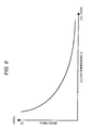
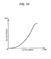
- the RAM temporarily stores variables necessary for performing the above-described program, and a storage unit stores detected values from a variety of sensors and stores the above-described program and mapping data shown in FIGS. 8 and 10 .
- the control unit 40 may be configured by a single ECU, or may be configured by a plurality of ECUs.
- the control unit 40 acquires information of an accelerator position Ac meaning a relative value of the operation amount of an accelerator pedal 81, from an accelerator sensor 82. Also, the control unit 40 acquires wheel speeds Vl and Vr from wheel speed sensors 85 and 86 for detecting the rotation speeds of the wheels Wl and Wr (which are not limited to driving wheels), and calculates the vehicle speed V of the vehicle based on the corresponding wheel speeds Vr and Vl. Thereafter, the control unit 40 calculates a required driving force based on the accelerator position Ac and the vehicle speed V.
- control unit 40 acquires information of a brake position Bk meaning a relative value of the operation amount of a brake pedal 83, from a brake sensor 84 for detecting the operation amount. Thereafter, the control unit 40 calculates a required braking force based on the brake position Bk.
- the control unit 40 calculates an input shaft rotation speed ⁇ i, which is the rotation speed of the input shaft 51 (the carrier 13), based on the rotation speed ⁇ MG1r of the first motor generator MG1 input from the rotation speed sensor MG1-1, the rotation speed ⁇ MG2r of the second motor generator MG2 (calculated from the vehicle speed V), and the gear ratio between the sun gear 11 and the inner gear 14a.
- a solid line represents a clutch torque map representing a relation between the clutch torque Tcr and a clutch stroke.
- the clutch 20 of the present embodiment in a standby position in which the clutch stroke is 0, the clutch 20 of the present embodiment is completely disconnected, and the clutch torque Tcr is 0. Thereafter, as the clutch stroke increases, the clutch torque Tcr increases, and when the clutch stroke is the maximum, the clutch 20 is completely engaged.
- the control unit 40 calculates the clutch stroke by referring to the clutch torque map shown in FIG. 10 for a target clutch torque Tct. Thereafter, the control unit 40 controls the clutch actuator 50 so that the calculated clutch stroke is obtained and controls the clutch 20 so that the clutch torque Tcr becomes the target clutch torque Tct.
- the vehicle travels in the electric traveling mode or the split traveling mode, and both traveling modes can be switched during traveling.
- the electric traveling mode is a mode in which the vehicle travels by the rotation driving force of only at least one of the first motor generator MG1 and the second motor generator MG2.
- the split traveling mode is a mode in which the vehicle travels by the rotation driving force of both at least one of the first motor generator MG1 and the second motor generator MG2 and the rotation driving force of the engine EG.
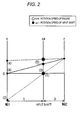
- the vertical axes correspond to the rotation speeds of respective rotary components.
- an area upper than 0 corresponds to normal rotation, and an area lower than 0 corresponds to reverse rotation.
- a reference symbol “s” represents the rotation speed of the sun gear 11
- a reference symbol “ca” represents the rotation speed of the carrier 13
- a reference symbol “r” represents the rotation speed of the ring gear 14. That is, the reference symbol “s” represents the rotation speed of the first motor generator MG1, and the reference symbol “ca” represents the rotation speed of the input shaft 51, and the reference symbol “r” represents the rotation speed of the second motor generator MG2 or a rotation speed proportional to the driving wheels Wl and Wr (the vehicle speed).
- the rotation speed ca becomes the same rotation speed as the rotation speed of the output shaft EG-1 of the engine EG.
- the interval between the vertical lines representing the rotation speeds "s" and "ca” is 1, the interval between the vertical lines representing the rotation speeds "ca” and “r” becomes the gear ratio ⁇ of the planetary gear mechanism 10 (the gear ratio of the sun gear 11 and the inner gear 14a (That is, [NUMBER OF TEETH OF SUN GEAR 11]/[NUMBER OF TEETH OF INNER GEAR 14a]).
- the first motor generator MG1 (the first rotor Ro1)
- the input shaft 51, and the second motor generator MG2 rotate in association with one another.
- the vehicle travels in the electric traveling mode.
- the control unit 40 controls the clutch actuator 50 so that the clutch 20 becomes the disconnected state.
- the engine EG and the input shaft 51 are disconnected.
- the control unit 40 outputs a control signal to the second inverter 32, thereby driving the second motor generator MG2 so that the required driving force is obtained.
- the second motor generator MG2 normally rotates.
- the engine EG since the engine EG has been disconnected from the input shaft 51, the engine EG is at a stop (the engine rotation speed ⁇ e is 0) (the state of (1) of FIG. 2 ).
- the control unit 40 outputs a control signal to the clutch actuator 50 so that the clutch actuator 50 connects the clutch 20, so that the output shaft EG-1 and the input shaft 51 are engaged, and then outputs control signals to the first inverter 31 and the second inverter 32, so that the first inverter 31 and the second inverter 32 drive the first motor generator MG1 and the second motor generator MG2, so that the required driving force is obtained.
- the first motor generator MG1 reversely rotates (the state of (2) of FIG.
- the second motor generator MG2 normally rotates, and the engine EG is at a stop (the state of (3) of FIG. 2 ).
- the friction torque of the engine EG which is a negative torque functions as a reaction receiver for supporting the carrier 13.
- the maximum rotation driving force which the first motor generator MG1 can output is limited to a rotation driving force at which a rotary torque transmitted to the input shaft 51 by the rotation driving force of the first motor generator MG1 becomes equal to or lower than the friction torque of the engine EG.
- the vehicle travels in the split traveling mode.
- the control unit 40 controls the clutch actuator 50 so that the clutch 20 becomes the connected state, and controls the engine EG so that a predetermined rotation driving force is generated by the engine EG.
- the engine EG and the input shaft 51 are connected, and the rotation driving force of the engine EG is input to the carrier 13.
- the rotation driving force of the engine EG input to the carrier 13 is distributed and transmitted to the sun gear 11 and the ring gear 14. That is, the rotation driving force of the engine EG is distributed to the first motor generator MG1 and the driving wheels Wl and Wr.
- the engine EG In the split traveling mode, the engine EG is maintained in a state where the efficiency is high (a state where the efficiency of fuel consumption is high). In this state, since the rotation driving force of the engine EG is distributed and transmitted to the first motor generator MG1, as shown by an alternate long and short dash lines in FIG. 2 , the first motor generator MG1 rotates normally ((4) of FIG. 2 ) and generates electric power. As a result, the first motor generator MG1 outputs a motor generator torque TMG1 of a reverse direction to the sun gear 11. That is, the first motor generator MG1 functions as a reaction receiver for supporting the reaction of an engine torque TE, so that the rotation driving force of the engine EG is distributed to the ring gear 14 and is transmitted to the driving wheels Wl and Wr. Then, the second motor generator MG2 is driven by a current generated by the first motor generator MG1 and a current supplied from the battery 33 and then drives the driving wheels Wl and Wr.
- the control unit 40 performs regenerative braking.
- the control unit 40 controls the clutch actuator 50 so that the clutch 20 becomes the disconnected state.
- the control unit 40 outputs a control signal to the second inverter 32 so that the second motor generator MG2 generates a regenerative braking force and generates electric power.
- the second motor generator MG2 generates a rotary torque of a reverse direction.
- a current generated by the second motor generator MG2 charges the battery 33.
- the control unit 40 controls the clutch actuator 50 so that the clutch 20 becomes the disconnected state and thus rotates the engine EG, so that the friction torque of the engine EG (so-called engine brake) is used to decelerate the vehicle.
- the control unit 40 operates the clutch actuator 50.
- the clutch 20 transitions from the connected state to the disconnected state, or the clutch 20 transitions from the disconnected state to the connected state. Therefore, it is possible to suppressing rusting of the clutch 20 due to continuous connection of the clutch 20.
- the description thereof will be made in detail.
- Step S201 the control unit 40 turns off a wetness flag, a under-drying flag, and a second-clutch-processing flag, and resets a timer to 0. If Step S201 finishes, the program proceeds to Step S202.
- the wetness flag represents that the clutch 20 is in a situation where the clutch 20 may be wet.
- the under-drying flag represents that the clutch 20 is to be dried.
- the second-clutch-processing flag represents that a second clutch heating process shown in FIG. 7 is being performed.
- Step S203 In a case where the control unit 40 determines that the clutch 20 is in the disconnected state in Step S202 ("YES” in Step S202), the program proceeds to Step S203. In a case where the control unit 40 determines that the clutch 20 is in the connected state in Step S202 ("NO” in Step S202), the program proceeds to Step S205. Also, a case where the clutch 20 is in the disconnected state in a state where the ignition is ON-state means that the clutch 20 was disconnected when the previous ignition was off, in order to suppress sticking of the clutch 20 in Step S211.
- Step S203 the control unit 40 turns the wetness flag to ON-state, and then the program proceeds to Step S204.
- Step S204 the control unit 40 sets the target clutch torque Tct.
- the target clutch torque Tct is calculated according to the traveling state of the vehicle. That is, in a case where the clutch 20 transitions from the connected state to the disconnected state like in a case where the vehicle travels in the electric traveling mode, the target clutch torque Tct is set to 0. Also, in a case where the vehicle transitions from the electric traveling mode to the split traveling mode, in order to control the clutch 20 in the disconnected state to connect, the control unit 40 calculates the target clutch torque Tct to gradually increase from 0 as time goes on so as to become a complete engagement clutch torque. If Step S204 finishes, the program proceeds to Step S205.
- Step S205 the control unit 40 performs a clutch-state updating process.
- This clutch-state updating process will be described below with reference to a flow chart shown in FIG. 4 . If the clutch-state updating process starts, the program proceeds to Step S301.
- Step S301 In a case where the control unit 40 determines that the wetness flag is ON-state in Step S301 ("YES” in Step S301), the program proceeds to Step S302. In a case where the control unit 40 determines that the wetness flag is OFF-state in Step S301 ("NO" in Step S301), the program proceeds to Step S305.
- Step S302 In a case where the control unit 40 determines that the clutch 20 is in a situation where the clutch 20 may not be wet in Step S302 ("YES" in Step S302), the program proceeds to Step S303. In a case where the control unit 40 determines that the clutch 20 is in a situation where the clutch 20 may be wet in Step S302 ("NO" in Step S302), the clutch-state updating process finishes, and the program proceeds to Step S206 of FIG. 3 .
- the control unit 40 determines that the clutch 20 is in a situation where the clutch 20 may be wet. Also, in a case of determining that it is raining at the place where the vehicle is traveling, based on the weather information acquired by the information acquiring unit 90, the control unit 40 determines that the clutch 20 is in a situation where the clutch 20 may be wet.
- the situation where the clutch 20 may be wet means a situation where there is a possibility of the rust formation on the clutch 20.
- the control unit 40 turns the wetness flag to OFF-state in Step S303, and turns the under-drying flag to ON-state in Step S304. If Step S304 finishes, the program proceeds to Step S320.
- Step S305 In a case where the control unit 40 determines that the clutch 20 is in a situation where the clutch 20 may be wet in Step S305 ("YES" in Step S305), the program proceeds to Step S306. In a case where the control unit 40 determines that the clutch 20 is not in a situation where the clutch 20 may be wet in Step S305 ("NO" in Step S305), the program proceeds to Step S308. Also, the determining method of Step S305 is the same as the above-described determining method of Step S302.
- the control unit 40 turns the wetness flag to ON-state in Step S306, and turns the under-drying flag to OFF-state in Step S307. If Step S307 finishes, the program proceeds to Step S320.
- Step S308 In a case where the control unit 40 determines that the under-drying flag is ON-state in Step S308 ("YES" in Step S308), the program proceeds to Step S309. In a case where the control unit 40 determines that the under-drying flag is OFF-state in Step S308 ("NO" in Step S308), the program proceeds to Step S320.
- Step S309 the control unit 40 increases the value of the timer by an increment, and then the program proceeds to Step S310.
- Step S310 determines that the value of the timer is larger than a drying time A in Step S310 ("YES" in Step S310)
- the program proceeds to Step S311.
- the control unit 40 determines that the value of the timer is equal to or smaller than the drying time A in Step S310 ("NO" in Step S310)
- the clutch-state updating process finishes, and the program proceeds to Step S206 of FIG. 3 .
- the drying time A is calculated by referring to drying-time mapping data, representing a relation between the clutch temperature Tc and the drying time A and shown in FIG. 8 , for the current temperature of the clutch 20.
- the clutch temperature Tc and the drying time A are inversely proportional to each other. That is, as the clutch temperature Tc increases, the drying time A decreases.
- Step S311 the control unit 40 turns the under-drying flag to OFF-state. If Step S311 finishes, the program proceeds to Step S320.
- Step S320 In a case where the control unit 40 determines that the under-drying flag is OFF-state in Step S320 ("YES" in Step S320), the program proceeds to Step S321. In a case where the control unit 40 determines that the under-drying flag is ON-state in Step S320 ("NO” in Step S320), the clutch-state updating process finishes, and the program proceeds to Step S206 of FIG. 3 .
- Step S321 the control unit 40 resets the timer. If Step S321 finishes, the clutch-state updating process finishes, and the program proceeds to Step S206 of FIG. 3 .
- Step S206 In a case where the control unit 40 determines that any one of the wetness flag and the under-drying flag is ON-state in Step S206 ("YES" in Step S206), the program proceeds to Step S207. In a case where the control unit 40 determines that both of the wetness flag and the under-drying flag are OFF-state in Step S206 ("NO" in Step S206), the program proceeds to Step S208.
- Step S208 the control unit 40 outputs a control signal to the clutch actuator 50, thereby controlling the clutch 20 so that the target clutch torque Tct is obtained. If Step S208 finishes, the program proceeds to Step S209.
- Step S207 the control unit 40 performs a clutch temperature control.
- the clutch temperature control will be described with reference to a flow chart shown in FIG. 5 . If the clutch temperature control starts, the program proceeds to Step S401 of FIG. 5 .
- Step S401 the control unit 40 calculates the clutch temperature Tc.
- the clutch temperature Tc means the temperature of the friction member 22a. Specifically, based on the housing inside temperature Th detected by the temperature sensor 26, the integrated value of the heat generation amount of the friction member 22a, the integrated value of the heat radiation amount of the whole of the clutch 20 and the friction member 22a, and the like, the control unit 40 estimates the clutch temperature Tc which is the current temperature of the friction member 22a. Also, the heat generation amount of the friction member 22a is calculated based on the clutch differential rotation speed ⁇ r which is the differential rotation speed of the clutch 20 in an engaged state (a difference between the engine rotation speed ⁇ e and the input shaft rotation speed ⁇ i) and the clutch torque Tcr. If Step S401 finishes, the program proceeds to Step S402.
- Step S402 determines that any one of the wetness flag and the under-drying flag is ON-state in Step S402 ("YES" in Step S402)
- the program proceeds to Step S403.
- the program proceeds to Step S410.
- Step S403 determines that the clutch temperature Tc is equal to or higher than a defined temperature T (for example, 120°C) in Step S403 ("YES" in Step S403).
- the program proceeds to Step S410.
- the control unit 40 determines that the clutch temperature Tc is lower than the defined temperature T in Step S403 ("NO" in Step S403), the program proceeds to Step S404.
- Step S404 determines that the vehicle is traveling in the electric traveling mode in Step S404 ("YES" in Step S404)
- the program proceeds to Step S405.
- the program proceeds to Step S407.
- Step S405 In a case where the control unit 40 determines that the clutch 20 is still in the disconnected state in Step S405 ("YES" in Step S405), the program proceeds to Step S406. In a case where the control unit 40 determines that the clutch 20 is in the engaged state in Step S405 ("NO” in Step S405), the program proceeds to Step S410. Although the vehicle is in the electric traveling mode, if the brake pedal 83 is stepped on when the battery 33 is full, a braking force according to the engine brake is generated in the engine EG, so that the clutch 20 is connected.
- Step S406 the control unit 40 performs a first clutch heating process.
- This first clutch heating process will be described with reference to a flow chart shown in FIG. 6 . If the first clutch heating process starts, the program proceeds to Step S701 of FIG. 6 .
- Step S701 In a case where the control unit 40 determines that the clutch differential rotation speed ⁇ r is lower than a third rotation speed (for example, 2000 rpm) in Step S701 ("YES" in Step S701), the program proceeds to Step S702. In a case where the control unit 40 determines that the clutch differential rotation speed ⁇ r is equal to or higher than the third rotation speed in Step S701 ("NO" in Step S701), the program proceeds to Step S704.
- a third rotation speed for example, 2000 rpm
- Step S702 In a case where the control unit 40 determines that the clutch differential rotation speed ⁇ r is equal to or higher than a fourth rotation speed (for example, 150 rpm) in Step S702 ("YES" in Step S702), the program proceeds to Step S703. In a case where the control unit 40 determines that the clutch differential rotation speed ⁇ r is lower than the fourth rotation speed in Step S702 ("NO" in Step S702), the program proceeds to Step S704.
- a fourth rotation speed for example, 150 rpm
- Step S703 the control unit 40 sets the target clutch torque Tct.
- the target clutch torque Tct is a clutch torque by which the clutch 20 in the half-clutch state generates a target clutch heat generation amount.
- the target clutch torque Tct is set to a smaller one of a half of the friction torque of the engine EG and 5/100 of the maximum torque which is generated by the engine EG. If Step S703 finishes, the program proceeds to Step S410 of FIG. 5 .
- Step S704 the control unit 40 sets the target clutch torque Tct to 0, that is, the control unit 40 sets the target clutch torque Tct so that the clutch 20 is disconnected. If Step S704 finishes, the first clutch heating process finishes, and then the program proceeds to Step S410 of FIG. 5 .
- Step S408 the program proceeds to Step S410.
- the second motor generator MG2 generates electric power to generate a regenerative braking force even in that the vehicle is traveling in the split traveling mode, the clutch 20 is disconnected in order to suppress occurrence of friction in the engine EG.
- Step S408 the control unit 40 performs a second clutch heating process.
- This second clutch heating process will be described with reference to a flow chart shown in FIG. 7 . If the second clutch heating process starts, the program proceeds to Step S801 of FIG. 7 .
- Step S801 In a case where the control unit 40 determines that the second-clutch-processing flag is ON-state in Step S801 ("YES" in Step S801), the program proceeds to Step S802. In a case where the control unit 40 determines that the second-clutch-processing flag is OFF-state in Step S801 ("NO" in Step S801), the program proceeds to Step S805.
- Step S802 In a case where the control unit 40 determines that the clutch differential rotation speed ⁇ r is lower than a first rotation speed (for example, 350 rpm) in Step S802 ("YES" in Step S802), the program proceeds to Step S803. In a case where the control unit 40 determines that the clutch differential rotation speed ⁇ r is equal to or higher than the first rotation speed in Step S802 ("NO" in Step S802), the program proceeds to Step S807.
- a first rotation speed for example, 350 rpm
- Step S803 In a case where the control unit 40 determines that the clutch differential rotation speed ⁇ r is equal to or higher than a second rotation speed (for example, 150 rpm) in Step S803 ("YES" in Step S803), the program proceeds to Step S804. In a case where the control unit 40 determines that the clutch differential rotation speed ⁇ r is lower than the second rotation speed in Step S803 ("NO" in Step S803), the program proceeds to Step S806.
- a second rotation speed for example, 150 rpm
- Step S804 the control unit 40 sets the target clutch torque Tct to a heating instruction torque Th.
- the heating instruction torque Th is set to a current clutch torque Tcr in Step S805 (to be described below). If Step S804 finishes, the program proceeds to Step S409 of FIG. 5 .
- Step S805 the control unit 40 sets the current clutch torque Tcr as the heating instruction torque Th. If Step S805 finishes, the program proceeds to Step S802.
- Step S806 the control unit 40 decreases the heating instruction torque Th by a defined value B and stores the decreased heating instruction torque Th. If Step S806 finishes, the program proceeds to Step S804.
- Step S807 the control unit 40 sets the heating instruction torque Th to a complete engagement torque which is the maximum torque that the clutch 20 can transmit, that is, the clutch torque Tcr of the clutch cover in the connected state. If Step S807 finishes, the program proceeds to Step S804.
- Step S409 the control unit 40 turns the second-clutch-heating-processing flag to ON-state. If Step S409 finishes, the program proceeds to Step S411.
- Step S410 the control unit 40 turns the second-clutch-heating-processing flag to OFF-state. If Step S410 finishes, the program proceeds to Step S411.
- Step S411 the control unit 40 calculates a clutch stroke by referring to a clutch torque map, shown in FIG. 10 , for the target clutch torque Tct. Thereafter, the control unit 40 controls the clutch actuator 50 so that the calculated clutch stroke is obtained, thereby controlling the clutch torque Tcr to become the target clutch torque Tct.
- Step S411 finishes, the program proceeds to Step S209 of FIG. 3 .
- Step S209 In a case where the control unit 40 determines that the ignition is OFF-state in Step S209 ("YES" in Step S209), the program proceeds to Step S210. In a case where the control unit 40 determines that the ignition is still ON-state in Step S209 ("NO” in Step S209), the program returns to Step S204.
- Step S210 In a case where the control unit 40 determines that any one of the wetness flag and the under-drying flag is ON-state in Step S210 ("YES" in Step S210), the program proceeds to Step S211. In a case where the control unit 40 determines that both of the wetness flag and the under-drying flag are off in Step S210 ("NO" in Step S210), the program proceeds to Step S212.
- Step S211 in a case where the clutch 20 is in the engaged state, the control unit 40 outputs a control signal to the clutch actuator 50, so that the clutch 20 is disconnected. If Step S211 finishes, the first rust-suppressing control of the clutch finishes, and the vehicle becomes the state incapable of traveling.
- Step S212 in a case where the clutch 20 is in the disconnected state, the control unit 40 outputs a control signal to the clutch actuator 50, so that the clutch 20 is connected. If Step S212 finishes, the first rust-suppressing control of the clutch finishes, and the vehicle becomes the state incapable of traveling.
- Step S501 the control unit 40 turns a clutch operation history to OFF-sate and stores the clutch operation history in the storage unit.
- the clutch operation history is a history in which the clutch 20 has transitioned from the connected state to the disconnected state. If Step S501 finishes, the program proceeds to Step S502.
- Step S502 the control unit 40 reads the value of the counter from the storage unit. If Step S502 finishes, the program proceeds to Step S503.
- Step S503 In a case where the control unit 40 determines that the value of the counter is larger than a defined value C (for example, five) in Step S503 ("YES" in Step S503), the program proceeds to Step S504. In a case where the control unit 40 determines that the value of the counter is equal to or smaller than the defined value C in Step S503 ("NO" in Step S503), the program proceeds to Step S505.
- a defined value C for example, five
- Step S504 the control unit 40 outputs a control signal to the clutch actuator 50, so that the clutch 20 is disconnected. Thereafter, the control unit 40 outputs a control signal to the first inverter 31, thereby rotating the first motor generator MG1 so that the clutch disc 22 which is an output-side member of the clutch 20 is rotated. As a result, the flywheel 21, the pressure plate 24, the clutch cover 23, and the clutch disc 22, which are input-side members of the clutch 20, rotate relatively, so that the phase of the clutch 20 changes. Next, the control unit 40 outputs a control signal to the clutch actuator 50, so that the clutch 20 is connected. If Step S504 finishes, the program proceeds to Step S505.
- Step S505 In a case where the control unit 40 determines that the vehicle is in the electric traveling mode in Step S505 ("YES" in Step S505), the program proceeds to Step S506. In a case where the control unit 40 determines that the vehicle is in the split traveling mode in Step S505 ("NO" in Step S505), the program proceeds to Step S513.
- Step S513 In a case where the control unit 40 determines that it is necessary to disconnect the clutch 20 in Step S513 ("YES” in Step S513), the program proceeds to Step S506. In a case where the control unit 40 determines that it is unnecessary to disconnect the clutch 20 in Step S513 ("NO” in Step S513), the program proceeds to Step S514. In the split traveling mode, a case where it is necessary to disconnect the clutch is a case where the second motor generator MG2 generates electric power, so that a regenerative braking force is generated.
- Step S506 the control unit 40 outputs a control signal to the clutch actuator 50, so that the clutch 20 is disconnected. If Step S506 finishes, the program proceeds to Step S507.
- Step S514 the control unit 40 outputs a control signal to the clutch actuator 50, so that the clutch 20 is connected. If Step S514 finishes, the program proceeds to Step S508.
- Step S507 the control unit 40 turns the clutch operation history to ON-state and stores the clutch operation history in the storage unit. If Step S507 finishes, the program proceeds to Step S508.
- Step S508 In a case where the control unit 40 determines that the ignition is OFF-state in Step S508 ("YES" in Step S508), the program proceeds to Step S509. In a case where the control unit 40 determines that the ignition has not OFF-state in Step S508 ("NO" in Step S508), the program proceeds to Step S505.
- Step S509 In a case where the control unit 40 determines that the clutch operation history is ON-state in Step S509 ("YES" in Step S509), the program proceeds to Step S510. In a case where the control unit 40 determines that the clutch operation history is OFF-state in Step S509 ("NO” in Step S509), the program proceeds to Step S512.
- Step S510 the control unit 40 resets the value of the counter to 0 and stores the value of the counter in the storage unit. If Step S510 finishes, the program proceeds to Step S511.
- Step S512 the control unit 40 increases the value of the counter by an increment of 1, and stores the value of the counter in the storage unit. If Step S512 finishes, the program proceeds to Step S511.
- Step S511 the control unit 40 outputs a control signal to the clutch actuator 50, so that the clutch 20 is connected. If Step S511 finishes, the second rust-suppressing control of the clutch finishes.
- the control unit 40 determines that there is a possibility of the rust formation on the clutch 20 ("YES” in the determination of Step S206 of FIG. 3 , “YES” in the determination of Step S210 of FIG. 3 , or “YES” in the determination of Step S503 of FIG. 9 )
- the control unit 40 operates the clutch actuator 50 in Step S211 of FIG. 3 , Step S411 of FIG. 5 , or Step S504 of FIG. 9 .
- the clutch 20 transitions from the connected state to the disconnected state, or the clutch 20 transitions from the disconnected state to the connected state. Therefore, it is possible to suppress rusting of the clutch 20 due to continuous connection of the clutch 20.
- the clutch 20 is connected, so that the rust formed on the clutch 20 is removed.
- the control unit 40 (the rust formation suppressing unit) operates the clutch actuator 50 in Step S208 of FIG. 3 or Step S504 of FIG. 9 , so that the clutch 20 is disconnected. Therefore, rusting of the clutch 20 due to continuous connection of the clutch 20 is suppressed by the operation of the clutch 20 in a disconnection direction.
- the control unit 40 (the rust formation suppressing unit) operates the clutch actuator 50 in Step S208 of FIG. 3 , thereby operating the clutch 20 in a connection direction. Therefore, even if the clutch 20 is disconnected and the sliding surface of the clutch 20 comes into contact with air and rust is formed on the sliding surface of the clutch 20, since the clutch 20 is operated in the connection direction so that the sliding surface of the clutch 20 is rubbed, it is possible to remove the rust formed on the sliding surface of the clutch 20. For this reason, in a case where the disconnected clutch 20 is connected again, it is possible to suppress rusting of the clutch 20 due to the rust formed on the sliding surface of the clutch 20.
- the control unit 40 (the rust formation suppressing unit) operates the clutch actuator 50 in Step S504 of FIG. 9 , so that the clutch 20 is disconnected. Therefore, when the vehicle becomes the state capable of traveling, since the clutch is disconnected, it is possible to suppress rusting of the clutch due to continuous connection of the clutch.
- the control unit 40 determines that there is a possibility of the rust formation on the clutch 20 ("YES" in the determination of Step S210 of FIG. 3 )
- the control unit 40 operates the clutch actuator 50 in Step S211, so that the clutch 20 is disconnected and the vehicle is to be the state incapable of traveling. Therefore, since the clutch 20 is in the disconnected state during a stop of the vehicle, it is possible to suppress the clutch 20 from becoming incapable of being disconnected due to rusting of the clutch 20 when the vehicle becomes the state capable of traveling again.
- the control unit 40 determines whether there is a possibility of the rust formation on the clutch 20, based on the rust information such as the location information and the weather information. That is, the control unit 40 determines whether the vehicle is traveling on road surface likely to be wet, such as a dry river bed or a coast, based on the location information of the vehicle, thereby determining whether there is a possibility of the rust formation on the clutch 20. Alternatively, the control unit 40 can determine whether the vehicle is traveling in a place where it is being raining, based on the weather information of the location of the vehicle, thereby determining a state where rust is likely to be formed on the clutch 20.
- the control unit 40 (the rust formation suppressing unit) operates the clutch actuator 50, thereby removing water onto the clutch 20. In this way, it is possible to suppress the rust formation on the clutch 20 in advance.
- Step S208 of FIG. 3 the control unit 40 (the rust formation suppressing unit) operates the clutch actuator 50 to put the clutch into 20 the half-clutch state. In this way, it is possible to heat the clutch 20. In a case where water is introduced to the clutch 20, it is possible to remove the water by drying. Therefore, it is possible to suppress the rust formation on the clutch 20 in advance. Also, even in a case where rust has been formed on a component of the clutch 20, the clutch 20 is put into the half-clutch state, so that the component of the clutch 20 is rubbed. Therefore, it is possible to remove the rust formed on the above-described component.
- Step S208 of FIG. 3 the control unit 40 (the rust formation suppressing unit) operates the clutch actuator 50 so that the clutch torque Tcr becomes the target clutch torque Tct and then put the clutch 20 into the half-clutch state.
- the clutch torque Tcr is controlled so as to be the target clutch torque Tct. Therefore, it is possible to reliably maintain the clutch 20 in the half-clutch state, and to reliably heat the clutch 20. For this reason, it is possible to reliably remove water onto the clutch 20 by drying, and even in a case where water is introduced to a component of the clutch 20, it is possible to reliably remove the water.
- Steps S807 and S804 of FIG. 7 the control unit sets the target clutch torque Tct to the complete engagement torque, and in Step S411 of FIG. 5 , the control unit operates the clutch actuator 50, so that the clutch 20 is connected. Therefore, the clutch 20 is suppressed from becoming the half-clutch state in a state where the clutch differential rotation speed ⁇ r is excessively high. For this reason, overheating of the clutch 20 is suppressed, and it is possible to suppress a decrease in the life of the clutch 20, and deterioration in the characteristics of the clutch 20.
- Steps S806 and S804 the control unit 40 (the rust formation suppressing unit) reduces the target clutch torque Tct.
- Step S411 of FIG. 5 the clutch differential rotation speed ⁇ r increases. Therefore, it is possible to reliably heat the clutch 20, and it is possible to reliably remove water onto the clutch 20 by drying.
- the control unit 40 finishes the first clutch heating process, so that the clutch 20 stops the half-clutch state and transitions to the disconnected state.
- the clutch differential rotation speed ⁇ r is excessively low, i.e. lower than the fourth rotation speed, a variation in the friction coefficient of the clutch disc 22 with the flywheel 21 and the pressure plate 24 increases, and thus it becomes impossible to heat the clutch 20 as aimed and it is impossible to sufficiently heat the clutch 20.
- Step S704 the control unit 40 (the rust formation suppressing unit) sets the target clutch torque Tct to 0, and in Step S208 of FIG. 3 , the control unit operates the clutch actuator 50 to put the clutch 20 into the disconnected state. Therefore, the clutch 20 is suppressed from becoming the half-clutch state in a state where the clutch differential rotation speed ⁇ r is excessively high.
- Step S504 of FIG. 9 after the control unit 40 (the rust formation suppressing unit) outputs control signals to the clutch actuator 50 and the first inverter 31 and the clutch 20 is disconnected, the phase of the clutch 20 is changed and then the clutch 20 is connected. In this way, it is possible to suppress sticking of the clutch 20 caused by connection of components of the clutch 20 at the same positions.
- the control unit 40 the rust formation suppressing unit
- the control unit 40 (the rust formation suppressing unit) does not perform the first clutch heating process of Step S406 and the second clutch heating process of Step S408, and the clutch actuator 50 is operated. In this way, the clutch 20 is suppressed from becoming the half-clutch state in a state where the clutch temperature Tc is equal to or higher than the defined temperature T. Therefore, overheating of the clutch 20 is suppressed, and it is possible to suppress a decrease in the life of the clutch 20 and deterioration of the clutch 20.
- both of the first rust-suppressing control of the clutch shown in FIG. 3 and the second rust-suppressing control of the clutch shown in FIG. 9 are performed.
- any one of the first rust-suppressing control of the clutch shown in FIG. 3 and the second rust-suppressing control of the clutch shown in FIG. 9 may be performed.
- Step S310 of FIG. 4 based on the housing inside temperature Th detected by the temperature sensor 26, the heat generation amount of the friction member 22a, and the heat radiation amount of the whole of the clutch 20 and the friction member 22a, the control unit 40 acquires the clutch temperature Tc, which is the current temperature of the friction member 22a, by estimation.
- a temperature detection sensor such as a radiation thermometer for detecting the temperature of the friction member 22a may be provided in the vicinity of the friction member 22a, so as to acquire the clutch temperature Tc.
- the control unit 40 calculates the input shaft rotation speed ⁇ i, which is the rotation speed of the input shaft 51, based on the rotation speed ⁇ MG1r of the first motor generator MG1 input from the rotation speed sensor MG1-1, the rotation speed ⁇ MG2r of the second motor generator MG2 (calculated from the vehicle speed V), and the gear ratio between the sun gear 11 and the inner gear 14a.
- an input shaft rotation speed detection sensor for detecting the rotation speed of the input shaft 51 may be provided in the vicinity of the input shaft 51, so as to directly detect the input shaft rotation speed ⁇ i.
- input-side members of the clutch 20 which are connected to the output shaft EG-1 are the flywheel 21, the pressure plate 24, and the clutch cover 23, and an output-side member of the clutch 20 which is connected to the input shaft 51 is the clutch disc 22.
- an input-side member of the clutch 20 may be the clutch disc 22, and output-side members of the clutch 20 may be the flywheel 21 and the clutch cover 23.
- the clutch 20 is a normally closed clutch.
- the technical idea of this disclosure can also be applied to a normally open clutch so that the clutch 20 becomes the disconnected state when the ignition is turned to OFF-state.
- the program proceeds to Step S507 in which the clutch operation history is turned on. Meanwhile, if Step S506 finishes, the program proceeds to Step S508.
- the clutch 20 when the clutch 20 is in the disconnected state for a long time, the clutch 20 is connected in Step S504 and then is disconnected. At this time, the clutch disc 22, the flywheel 21, and the pressure plate 24 which are sliding members of the clutch 20 are rubbed against one another, so that the rust formed thereon is removed.
- the clutch 20 is a dry-type single-plate clutch.
- the technical idea of this disclosure can also be applied to a hybrid driving apparatus 100 including a dry-type multi-plate clutch having a plurality of clutch discs 22.
- Step S504 the control unit disconnects and connects the clutch 20, thereby suppressing sticking of the clutch 20.
- the control unit 40 may acquire date and time from the information acquiring unit 90 or the like. In a case where a defined time is elapsed from the previous operation date and time of the clutch 20 in Step S503, the control unit 40 may operate the clutch 20 in Step S504, thereby suppressing sticking of the clutch 20.
- Step S504 of FIG. 9 the control unit 40 rotates the first motor generator MG1, thereby changing the phase of the clutch 20.
- the control unit 40 may rotate the engine EG, thereby changing the phase of the clutch 20.
- Step S504 of FIG. 9 the control unit 40 may output a control signal to the clutch actuator 50, thereby repeating disconnecting and connecting of the clutch 20 a predetermined number of times so as to suppress sticking of the clutch 20.
- the first motor generator MG1 and the engine EG may not be rotated.
- the clutch actuator 50 is an electric clutch actuator configured so that the clutch torque Tcr is controlled by the clutch stroke.
- the clutch actuator 50 may be a clutch actuator configured so that the clutch torque Tcr is controlled by a hydraulic pressure, an air pressure, a voltage, a current, a load, or a pressure.
- the control unit 40 determines a situation where the clutch 20 may be wet, that is, whether there is a possibility of the rust formation on the clutch 20, based on the location information acquired by the location information acquiring unit 90a or the weather information acquired by the weather information acquiring unit 90b.
- the control unit may determine whether there is a possibility of the rust formation on the clutch 20, based on rust information such as the humidity or temperature of ambient air of the vehicle traveling.
- the information acquiring unit 90 for acquiring the rust information is a temperature sensor, a humidity sensor, or the like.
- the control unit may determine whether there is a possibility of the rust formation on the clutch 20, based on a detection signal from a raindrop sensor attached to the vehicle.
- hybrid driving apparatus 200 of a second embodiment differences from the hybrid driving apparatus 100 of the first embodiment will be described with reference to FIG 11 .
- Components having the same structures as those of the hybrid driving apparatus 100 of the first embodiment are denoted by the same reference symbols as those of the hybrid driving apparatus 100 of the first embodiment, and detailed descriptions will be omitted.
- the first rotor Ro1 of the first motor generator MG1 is connected to the input shaft 51 and is also connected to the ring gear 14 of the planetary gear mechanism 10. Further, the second rotor Ro2 of the second motor generator MG2 is connected to the sun gear 11 of the planetary gear mechanism 10.
- An output gear 13a is formed on the carrier 13. The output gear 13a and the input gear 72 are engaged with each other.
- the ring gear 14 is configured to be rotatable or fixed with respect to a housing 201 by a brake B.
- the brake B is configured to be controlled by the control unit 40.
- control unit 40 controls the clutch actuator 50 so that the clutch 20 becomes the disconnected state, and the control unit 40 controls the brake B so that the ring gear 14 is fixed to the housing 201. Thereafter, the control unit 40 outputs a control signal to the second inverter 32, thereby driving the second motor generator MG2 so that the required driving force is obtained.
- control unit 40 controls the clutch actuator 50 so that the clutch 20 becomes the disconnected state, and the control unit 40 controls the brake B so that the ring gear 14 becomes rotatable with respect to the housing 201. Thereafter, the control unit 40 outputs control signals to the first inverter 31 and the second inverter 32, thereby driving the first motor generator MG1 and the second motor generator MG2 so that the required driving force is obtained.
- control unit 40 controls the clutch actuator 50 so that the clutch 20 becomes the engaged state, and the control unit 40 controls the brake B so that the ring gear 14 becomes rotatable with respect to the housing 201. Thereafter, the control unit 40 outputs a control signal to the second inverter 32, thereby driving the second motor generator MG2, and the control unit 40 controls the engine EG so that the engine EG generates a predetermined rotation driving force.
- the engine EG and the input shaft 51 are connected, and the rotation driving force of the engine EG is input to the first motor generator MG1 and to the ring gear 14.
- the first motor generator MG1 generates electric power by the rotation driving force of the engine EG.
- the rotation driving force of the engine EG and the rotation driving force of the second motor generator MG2 input to the ring gear 14 are transmitted to the driving wheels Wr and Wl.
- hybrid driving apparatus 300 of a third embodiment differences from the hybrid driving apparatus 100 of the first embodiment will be described with reference to FIG 12 .
- Components having the same structures as those of the hybrid driving apparatus 100 of the first embodiment are denoted by the same reference symbols as those of the hybrid driving apparatus 100 of the first embodiment, and detailed descriptions will be omitted.
- the hybrid driving apparatus 300 of the third embodiment has an automatic transmission 8, instead of the second motor generator MG2 and the planetary gear mechanism 10.
- the first rotor Ro1 of the first motor generator MG1 is connected to the input shaft 51. Between the first motor generator MG1 and the differential mechanism DF, the automatic transmission 8 is installed. That is, the first rotor Ro 1 is connected to the transmission input shaft 8-1 of the automatic transmission 8, and the transmission output shaft 8-2 of the automatic transmission 8 is connected to the differential mechanism DF.
- the automatic transmission 8 is a transmission having a gearshift mechanism for varying a transmission gear ratio which is obtained by dividing the rotation speed of the transmission input shaft 8-1 by the rotation speed of the transmission output shaft 8-2.
- Examples of the automatic transmission 8 include an automatic transmission having a torque converter or a planetary gear mechanism, an automatic/manual transmission, a dual-clutch transmission, and a non-stage transmission (CVT).
- the gearshift mechanism operates by a transmission actuator 8-5.
- the transmission actuator 8-5 operates the gearshift mechanism based on a gearshift command output from the control unit 40.
- hybrid driving apparatus 400 of a fourth embodiment differences from the hybrid driving apparatus 300 of the third embodiment will be described with reference to FIG 13 .
- Components having the same structures as those of the hybrid driving apparatus 300 of the third embodiment are denoted by the same reference symbols as those of the hybrid driving apparatus 300 of the third embodiment, and detailed descriptions will be omitted.
- the first motor generator MG1 is installed between the automatic transmission 8 and the differential mechanism DF. That is, the input shaft 51 is the input shaft of the automatic transmission 8, and the transmission output shaft 8-2 is connected to the first rotor Ro1, and the first rotor Ro 1 is connected to the differential mechanism DF.
- an input shaft rotation speed sensor 8-3 for detecting the input shaft rotation speed ⁇ i and outputting a detection signal to the control unit 40 is provided.
Landscapes
- Engineering & Computer Science (AREA)
- Mechanical Engineering (AREA)
- Transportation (AREA)
- Chemical & Material Sciences (AREA)
- Combustion & Propulsion (AREA)
- General Engineering & Computer Science (AREA)
- Automation & Control Theory (AREA)
- Physics & Mathematics (AREA)
- Fluid Mechanics (AREA)
- Hybrid Electric Vehicles (AREA)
- Electric Propulsion And Braking For Vehicles (AREA)
- Hydraulic Clutches, Magnetic Clutches, Fluid Clutches, And Fluid Joints (AREA)
Abstract
Description
- This disclosure relates to a hybrid driving apparatus which has a clutch that disengageably connects an output shaft of an engine and an input shaft that rotates in association with driving wheels, and a motor generator that rotates in association with rotation of the input shaft.
- Japanese Patent Application Laid-Open No.
2010-76678 2010-76678 - In this hybrid vehicle, in order to suppress a loss according to a drag of a clutch during clutch disconnection, it is general to use a dry-type clutch. In this dry-type clutch, in order to suppress overheating of a clutch plate, traveling air is introduced into the clutch, so that the clutch plate is cooled.
- As described above, since traveling air is introduced into the dry-type clutch, in a case where road surface is wet, according to introduction of traveling air, water is also introduced into the dry-type clutch. Also, in the hybrid vehicle, in a case of a split traveling mode, since the clutch is maintained at a connected state, the frequency of clutch disconnection is low. Therefore, if the connected state of the clutch continues, the clutch may be rusted and be firmly fixed, so that the clutch becomes unable to be disconnected.
- This disclosure was made in view of these circumstances, and this disclosure provides a technology, capable of suppressing rusting of a clutch in a hybrid driving apparatus including the clutch that disengageably connects an output shaft of an engine and an input shaft which rotates in association with driving wheels, and a motor generator that rotates in association with rotation of the input shaft.
- In view of the above, a hybrid driving apparatus of this disclosure includes: an engine configured to output a rotation driving force to an output shaft; an input shaft configured to rotate in association with rotation of driving wheels of a vehicle; a clutch that is provided between the output shaft and the input shaft to disengageably connect the output shaft and the input shaft; a clutch actuator configured to operate the clutch; a motor generator configured to rotate in association with rotation of the input shaft; a rust formation determining unit configured to determine whether there is a possibility of a rust formation on the clutch; and a rust formation suppressing unit configured to operate the clutch actuator in a case where the rust formation determining unit determines that there is the possibility of the rust formation on the clutch.
- According to this configuration, in a case where the rust formation determining unit determines that there is a possibility of the rust formation on the clutch, the rust formation suppressing unit operates the clutch actuator. As a result, the clutch transitions from a connected state to a disconnected state, or the clutch transitions from the disconnected state to the connected state. Therefore, it is possible to suppress rusting of the clutch according to continuous connection of the clutch. Also, in a case where the clutch is maintained in the disconnected state, the clutch is connected so that the rust formed on the clutch is removed.
- In the above-described hybrid driving apparatus, in a case where the clutch is in a connected state, the rust formation suppressing unit may operate the clutch actuator to operate the clutch in a disconnection direction.
- According to this configuration, in a case where the clutch is in the connected state, the rust formation suppressing unit operates the clutch actuator, so that the clutch is disconnected. Therefore, rusting of the clutch due to continuous connection of the clutch is suppressed by the operation of the clutch in the disconnection direction.
- In the above-described hybrid driving apparatus, in a case where the clutch is in a disconnected state, the rust formation suppressing unit may operate the clutch actuator to operate the clutch in a connection direction.
- According to this configuration, in a case where the clutch is in the disconnected state, the rust formation suppressing unit operates the clutch actuator, thereby operating the clutch in the connection direction. Therefore, even if the clutch is disconnected and the sliding surface of the clutch comes into contact with air, so that rust is formed on the sliding surface of the clutch, the clutch is operated in the connection direction so that the sliding surface of the clutch is rubbed, so that it is possible to remove the rust formed on the sliding surface of the clutch. For this reason, in a case where the disconnected clutch is connected again, it is possible to suppress rusting of the clutch and a change in the characteristics of the clutch due to the rust formed on the sliding surface of the clutch.
- In the above-described hybrid driving apparatus, when the vehicle transitions from a state incapable of traveling to a state capable of traveling, in a case where the rust formation determining unit determines that the clutch is maintained in the connected state and there is the possibility of the rust formation on the clutch, the rust formation suppressing unit may operate the clutch actuator to put the clutch into the disconnected state.
- According to this configuration, when the vehicle transitions from the state incapable of traveling to the state capable of traveling, in a case where the rust formation determining unit determines that the clutch is maintained in the connected state and the clutch rusts, the rust formation suppressing unit operates the clutch actuator, so that the clutch is disconnected. Therefore, if the vehicle becomes the state capable of traveling, the clutch is disconnected, and thus it is possible to suppress rusting of the clutch due to continuous connection of the clutch and to suppress the clutch from becoming incapable of being disconnected.
- In the above-described hybrid driving apparatus, when the vehicle transitions from the state capable of traveling to the state incapable of traveling, in a case where the rust formation determining unit determines that there is a possibility of the rust formation on the clutch, the rust formation suppressing unit may operate the clutch actuator to put the clutch into the disconnected state and then put the vehicle into the state incapable of traveling.
- According to this configuration, when the vehicle transitions from the state capable of traveling to the state incapable of traveling, in a case where the rust formation determining unit determines that there is a possibility of the rust formation on the clutch, the rust formation suppressing unit operates the clutch actuator to put the clutch into the disconnected state and then puts the vehicle into the state incapable of traveling. Therefore, since the clutch is in the disconnected state during a stop of the vehicle, it is possible to suppress the clutch from becoming incapable of being disconnected due to rusting of the clutch when the vehicle becomes the state capable of traveling again.
- The above-described hybrid driving apparatus may include a rust information acquiring unit that acquires rust information relating to the rust formation on the clutch, wherein based on the rust information, the rust formation determining unit may determine whether there is a possibility of the rust formation on the clutch.
- According to this configuration, the rust formation determining unit determines whether there is a possibility of the rust formation on the clutch, based on the rust information. Therefore, it is possible to more reliably determine the possibility of the rust formation on the clutch. For this reason, in a case where there is a possibility of the rust formation on the clutch, the rust formation suppressing unit operates the clutch actuator, thereby capable of suppressing the rust formation on the clutch in advance.
- In the above-described hybrid driving apparatus, the rust information acquiring unit may acquire the rust information from an outside of the vehicle.
- According to this configuration, the rust information acquiring unit acquires the rust information from the outside of the vehicle. Therefore, for example, based on the location information of the vehicle or the weather information which is the rust information acquired from the outside, it is determined whether there is a possibility of the rust formation on the clutch. Therefore, it is possible to more reliably determine the possibility of the rust formation on the clutch.
- In the above-described hybrid driving apparatus, the rust formation suppressing unit operates the clutch actuator to put the clutch into a half-clutch state.
- According to this configuration, the rust formation suppressing unit operates the clutch actuator to put the clutch into the half-clutch state. In this way, it is possible to heat the clutch. In a case where water is introduced to the clutch, it is possible to dry the clutch, thereby removing the water. Therefore, it is possible to suppress the rust formation on the clutch in advance. Also, even in a case where rust is formed on a component of the clutch, the clutch is put into the half-clutch state, so that the component of the clutch is rubbed. Therefore, it is possible to remove the rust formed on the above-described component.
- In the above-described hybrid driving apparatus, in a case where a clutch differential rotation speed is lower than a first rotation speed, the rust formation suppressing unit may operate the clutch actuator so that the clutch torque of the clutch becomes a target clutch torque to put the clutch into the half-clutch state, and wherein in a case where the clutch differential rotation speed is equal to or higher than the first rotation speed, the rust formation suppressing unit may operate the clutch actuator to put the clutch into the connected state.
- According to this configuration, in a case where the clutch differential rotation speed is lower than the first rotation speed, the rust formation suppressing unit operates the clutch actuator so that the clutch torque becomes the target clutch torque to put the clutch into the half-clutch state. In this way, the clutch torque is controlled so as to be the target clutch torque. Therefore, it is possible to reliably maintain the clutch in the half-clutch state, and to reliably heat the clutch. For this reason, it is possible to dry the clutch, thereby reliably removing water onto the clutch, and even in a case where water is introduced to a component of the clutch, it is possible to reliably remove the water.
- Also, in a case where the clutch differential rotation speed is equal to or higher than the first rotation speed, the rust formation suppressing unit operates the clutch actuator to put the clutch into the connected state. Therefore, the clutch is suppressed from becoming the half-clutch state in a state where the clutch differential rotation speed is excessively high. For this reason, overheating of the clutch is suppressed, and it is possible to suppress a decrease in the life of the clutch, and deterioration in the characteristics of the clutch. Also, it is possible to suppress a feeling of deceleration according to a deficiency in transmitting the driving force from the engine, and a decrease in the power generation amount of the motor generator, due to excessive increasing of the clutch differential rotation speed.
- In the above-described hybrid driving apparatus, in a case where the clutch differential rotation speed of the clutch is lower than the first rotation speed and is also lower than a second rotation speed lower than the first rotation speed, the rust formation suppressing unit may decrease the target clutch torque.
- According to this configuration, in a case where the clutch differential rotation speed of the clutch is lower than the first rotation speed, and is also lower than the second rotation speed lower than the first rotation speed, the rust formation suppressing unit reduces the target clutch torque. As a result, the clutch differential rotation speed increases. Therefore, it is possible to reliably heat the clutch, and it is possible to dry the clutch, thereby reliably removing water onto the clutch.
- In the above-described hybrid driving apparatus, the rust formation suppressing unit may operate the clutch actuator to put the clutch into a half-clutch state.
- According to this configuration, the rust formation suppressing unit operates the clutch actuator to put the clutch into the half-clutch state. In this way, it is possible to heat the clutch. In a case where water is introduced to the clutch, it is possible to dry the clutch, thereby removing the water. Therefore, it is possible to suppress the rust formation on the clutch in advance. Also, even in a case where rust is formed on a component of the clutch, the clutch is put into the half-clutch state, so that the component of the clutch is rubbed. Therefore, it is possible to remove the rust formed on the above-described component.
- In the above-described hybrid driving apparatus, in a case where the clutch differential rotation speed of the clutch is equal to or higher than a third rotation speed, the rust formation suppressing unit may operate the clutch actuator to put the clutch into the disconnected state.
- According to this configuration, in a case where the clutch differential rotation speed of the clutch is equal to or higher than the third rotation speed, the rust formation suppressing unit operates the clutch actuator to put the clutch into the disconnected state. In this way, the clutch is suppressed from becoming the half-clutch state in a state where the clutch differential rotation speed is excessively high. Therefore, the clutch differential rotation speed is suppressed from excessively increasing, resulting in a rapid rise in the temperature of the clutch and overheating of the clutch, and it is possible to suppress a decrease in the life of the clutch and deterioration in the characteristics of the clutch.
- In the above-described hybrid driving apparatus, in a case where the clutch differential rotation speed of the clutch is lower than a fourth rotation speed, the rust formation suppressing unit may operate the clutch actuator to put the clutch into the disconnected state.
- According to this configuration, in a case where the clutch differential rotation speed of the clutch is lower than the fourth rotation speed, the rust formation suppressing unit operates the clutch actuator to put the clutch into the disconnected state. In this way, it is possible to suppress a variation in the friction coefficient of the inside of the clutch from excessively increasing due to the clutch differential rotation speed which is excessively low, i.e. lower than the fourth rotation speed, so that it becomes impossible to heat the clutch as aimed.
- In the above-described hybrid driving apparatus, the rust formation suppressing unit may changes a phase of the clutch after disconnecting the clutch and then, and then the rust formation suppressing unit controls the clutch to be connected.
- According to this configuration, after disconnecting the clutch, the rust formation suppressing unit changes the phase of the clutch, and then connects the clutch. In this way, it is possible to suppress sticking of the clutch due to connecting of components of the clutch at the same positions.
- The above-described hybrid driving apparatus may includes a clutch temperature acquiring unit configured to acquire a current temperature of the clutch, in a case where the temperature of the clutch is equal to or higher than a defined temperature, the rust formation suppressing unit may not operate the clutch actuator.
- According to this configuration, in a case where the temperature of the clutch is equal to or higher than the defined temperature, the rust formation suppressing unit does not operate the clutch actuator. Therefore, the clutch is suppressed from becoming the half-clutch state in a state where the temperature of the clutch is equal to or higher than the defined temperature. For this reason, in a case where the temperature of the clutch reaches a temperature sufficient to dry the clutch, unnecessary heating of the clutch is not performed, and it is possible to suppress a decrease in the power generation amount and a loss of the driving energy of the motor generator. Also, overheating of the clutch is suppressed, and it is possible to suppress a decrease in the life of the clutch, and deterioration of the clutch.
- The foregoing and additional features and characteristics of this disclosure will become more apparent from the following detailed descriptions considered with the reference to the accompanying drawings, wherein:
-
FIG. 1 is an explanatory view illustrating the configuration of a hybrid driving apparatus of a first embodiment; -
FIG. 2 is a velocity diagram of a planetary gear mechanism in an electric traveling mode and a split traveling mode; -
FIG. 3 is a flow chart illustrating a first rust-suppressing control of a clutch; -
FIG. 4 is a flow chart illustrating a clutch-state updating process which is a subroutine of the first rust-suppressing control of the clutch; -
FIG. 5 is a flow chart illustrating a clutch temperature control which is another subroutine of the first rust-suppressing control of the clutch; -
FIG. 6 is a flow chart illustrating a first clutch heating process which is a subroutine of the clutch temperature control; -
FIG. 7 is a flow chart illustrating a second clutch heating process which is another subroutine of the clutch temperature control; -
FIG. 8 shows drying-time mapping data representing a relation between temperature of the clutch and drying time; -
FIG. 9 is a flow chart illustrating a second rust-suppressing control of the clutch; -
FIG. 10 shows a clutch torque map representing a relation between clutch stroke and clutch torque; -
FIG. 11 is an explanatory view illustrating the configuration of a hybrid driving apparatus of a second embodiment; -
FIG. 12 is an explanatory view illustrating the configuration of a hybrid driving apparatus of a third embodiment; and -
FIG. 13 is an explanatory view illustrating the configuration of a hybrid driving apparatus of a fourth embodiment. - Hereinafter, a
hybrid driving apparatus 100 of an embodiment (first embodiment) of this disclosure will be described with reference to the accompanying drawings. InFIG. 1 , broken lines represent transmission paths of a variety of information, and alternate long and short dash lines represent transmission paths of electric power. A hybrid vehicle (hereinafter, referred to simply as a vehicle) has thehybrid driving apparatus 100. Thehybrid driving apparatus 100 of the present embodiment includes an engine EG, a first motor generator MG1, a second motor generator MG2, aplanetary gear mechanism 10, a clutch 20, afirst inverter 31, asecond inverter 32, abattery 33, aclutch actuator 50, acontrol unit 40, and aninformation acquiring unit 90. - In the following description, the state of the clutch 20 until the clutch 20 being in a disconnected state becomes a connected state, that is, the state of the clutch 20 in which there is a clutch differential rotation speed Δωr is referred to as a half-clutch state or the engagement state of the clutch 20.
- The engine EG is a gasoline engine, diesel engine, or the like which uses hydrocarbon-based fuel such as gasoline or light oil, and gives a rotation driving force to driving wheels Wl and Wr. The engine EG outputs the rotation driving force to an output shaft EG-1.
- In the vicinity of the output shaft EG-1, an engine rotation speed sensor EG-2 is installed. The engine rotation speed sensor EG-2 detects an engine rotation speed me which is the rotation speed of the output shaft EG-1, and outputs the detection signal of the engine rotation speed to the
control unit 40. Also, the engine EG includes a fuel injection device (not shown) for injecting fuel into an air intake port and each cylinder. In a case where the engine EG is a gasoline engine, in each cylinder, a spark plug (not shown) is provided. - The clutch 20, which is an arbitrary type of clutch, is provided between the output shaft EG-1 and an
input shaft 51 of theplanetary gear mechanism 10 and disengageably connects the output shaft EG-1 and theinput shaft 51, thereby electronically controlling a clutch torque Tcr which is a transmission torque between the output shaft EG-1 and theinput shaft 51. In the present embodiment, the clutch 20 is a dry-type normally-closed single-plate clutch, and includes a flywheel 21, aclutch disc 22, aclutch cover 23, apressure plate 24, and adiaphragm spring 25. - The clutch 20 is a normally-closed clutch to be in the connected state in a case where an ignition is OFF-state. The reason is that it is possible to travel by the driving force of the engine EG even if the
clutch actuator 50 breaks down. - The flywheel 21 is a circular plate having predetermined mass, and is connected to the output shaft EG-1 and rotates integrally with the output shaft EG-1. The
clutch disc 22 is a circular plate having afriction member 22a provided at an outer peripheral portion thereof and faces the flywheel 21 so as to be able to come into contact with and separate from the flywheel 21. Thefriction member 22a is a so-called clutch lining and is configured by an aggregate such as a metal, a binder such as a synthetic resin for combining the aggregate, and the like. Theclutch disc 22 is connected to theinput shaft 51, and rotates integrally with theinput shaft 51. - The
clutch cover 23 includes acylindrical portion 23a provided on the outer periphery side of theclutch disc 22 so as to be connected to the outer edge of the flywheel 21, and an annular-disc-shaped sideperipheral wall 23 that extends from an end portion of thecylindrical portion 23a, which is placed on the opposite side to the connection portion with the flywheel 21, toward the inner side in a radial direction. Thepressure plate 24 has an annular disc shape, and is provided to face the opposite side of theclutch disc 22 to the surface of theclutch disc 22 facing the flywheel 21 so that thepressure plate 24 can come into contact with and separate from theclutch disc 22. - The
diaphragm spring 25 is a kind of so-called disc spring, and includes a diaphragm formed to be inclined in the thickness direction of thediaphragm spring 25. An intermediate portion of thediaphragm spring 25 in the radial direction abuts on the inner edge of the sideperipheral wall 23b of theclutch cover 23, and the outer edge of thediaphragm spring 25 abuts on thepressure plate 24. - The
diaphragm spring 25 presses theclutch disc 22 against the flywheel 21 with thepressure plate 24 interposed between thediaphragm spring 25 and thepressure plate 24. In this state, thefriction member 22a of theclutch disc 22 is pressed by the flywheel 21 and thepressure plate 24, and due to the frictional force of thefriction member 22a with the flywheel 21 and thepressure plate 24, theclutch disc 22 and the flywheel 21 integrally rotate, and the output shaft EG-1 and theinput shaft 51 are connected. - Inside a housing (not shown) for storing the clutch 20, a
temperature sensor 26 is installed. A housing inside temperature Th detected by thetemperature sensor 26 is input to thecontrol unit 40. - The
clutch actuator 50 operates the clutch 20. That is, based on commands of thecontrol unit 40, theclutch actuator 50 presses the inner edge portion of thediaphragm spring 25 against the flywheel (21) side, or releases the pressing, thereby varying the clutch torque Tcr of the clutch 20. - The
clutch actuator 50 includes an electric motor, a worm gear, and a worm member. The worm gear is installed on the rotating shaft of the electric motor and is engaged with the worm member. By the worm gear and the worm member, rotational movement of the electric motor is converted into linear movement. - If the
clutch actuator 50 presses the inner edge portion of thediaphragm spring 25 toward the flywheel (21) side, thediaphragm spring 25 is deformed so that the outer edge of thediaphragm spring 25 is deformed in a direction away from the flywheel 21. Then, due to the deformation of thediaphragm spring 25, the pressing force of the flywheel 21 and thepressure plate 24 pressing theclutch disc 22 decreases gradually, and the clutch torque Tcr, which is the transmission torque between theclutch disc 22, and the flywheel 21 and thepressure plate 24, also decreases gradually, so that the output shaft EG-1 and theinput shaft 51 are disconnected. - As described above, the
control unit 40 drives theclutch actuator 50, thereby arbitrarily varying the clutch torque Tcr between theclutch disc 22, and the flywheel 21 and thepressure plate 24. Also, since theclutch actuator 50 has the worm gear and the worm member, even if supply of electric power to the electric motor stops, the current state of the clutch 20 is maintained. That is, in a case where the clutch 20 is in the disconnected state, the disconnected state is maintained. In a case where the clutch 20 is in the connected state, the connected state is maintained. - The first motor generator MG1 operates as a motor for applying a rotation driving force to the driving wheels Wl and Wr, and also operates as an electricity generator for converting the kinetic energy of the vehicle into electric power. The first motor generator MG1 includes a first stator St1 fixed to a case (not shown), and a first rotor Ro1 rotatably installed on the inner periphery side of the first stator St1. Also, in the vicinity of the first rotor Ro1, a rotation speed sensor MG1-1 for detecting the rotation speed ωMG1r of the first motor generator MG1 (the first rotor Ro1) and outputting the detected detection signal to the
control unit 40 is installed. - The
first inverter 31 is electrically connected to the first stator St1 and thebattery 33. Also, thefirst inverter 31 is connected to thecontrol unit 50 so that communication is possible. On a control signal from thecontrol unit 40, thefirst inverter 31 converts a DC current, which is supplied from thebattery 33, into an AC current with boosting, and then supplies the AC current to the first stator St1, thereby a rotation driving force is generated in the first motor generator MG1 so that the first motor generator MG1 functions as a motor. Also, based on a control signal from thecontrol unit 40, thefirst inverter 31 makes the first motor generator MG1 function as an electricity generator, thereby converting the AC current, which is generated by the first motor generator MG1, into a DC current while lowering a voltage, so that thebattery 33 is charged. - The second motor generator MG2 operates as a motor for applying a rotation driving force to the driving wheels Wl and Wr and also operates as an electricity generator for converting the kinetic energy of the vehicle into electric power. The second motor generator MG2 includes a second stator St2 fixed to a case (not shown), and a second rotor Ro2 rotatably installed on the inner periphery side of the second stator St2.
- The
second inverter 32 is electrically connected to the second stator St2 and thebattery 33. Also, thesecond inverter 32 is communicatably connected to thecontrol unit 40. Based on a control signal from thecontrol unit 40, thesecond inverter 32 converts a DC current, which is supplied from thebattery 33, into an AC current with boosting, and then supplies the AC current to the second stator St2. Thereby, a rotation driving force is generated in the second motor generator MG2 so that the second motor generator MG2 functions as a motor. Also, based on a control signal from thecontrol unit 40, thesecond inverter 32 makes the second motor generator MG2 function as an electricity generator, thereby converting the AC current, which is generated by the second motor generator MG2, into a DC current while lowering a voltage, so that thebattery 33 is charged. - The
planetary gear mechanism 10 distributes the rotation driving force of the engine EG to the first motor generator MG1 and a differential mechanism DF (to be described below), and includes asun gear 11, a plurality ofplanetary gears 12, acarrier 13, and aring gear 14. Thesun gear 11 is connected to the first rotor Ro1, and rotates integrally with the first rotor Ro1. - The plurality of
planetary gears 12 is disposed around thesun gear 11, and is engaged with thesun gear 11. Thecarrier 13 pivotally supports the plurality ofplanetary gears 12 so that theplanetary gears 12 are rotatable, and is connected to theinput shaft 51, and rotates integrally with theinput shaft 51. Thering gear 14 has a ring shape and has aninner gear 14a formed on the inner periphery side thereof, and anoutput gear 14b is formed on the outer periphery side thereof. Theinner gear 14a is engaged with the plurality ofplanetary gears 12. - A
reduction gear 60 includes afirst gear 61, asecond gear 62, and a connection shaft 63. Thefirst gear 61 is engaged with theoutput gear 14b of thering gear 14 while being engaged with anoutput gear 71 which rotates integrally with the second rotor Ro2. Thesecond gear 62 is connected to thefirst gear 61 by the connection shaft 63, and rotates integrally with thefirst gear 61. Also, the diameter and number of teeth of thesecond gear 62 are set to be smaller than those of thefirst gear 61. Thesecond gear 62 is engaged with aninput gear 72. - The differential mechanism DF distributes the rotation driving force transmitted to the
input gear 72, to driveshafts input shaft 51 is rotatably connected to the driving wheels Wl and Wr through theplanetary gear mechanism 10, thereduction gear 60, the differential mechanism DF, and thedrive shafts input shaft 51 rotates in association with rotation of the driving wheels Wl and Wr. - Also, between the engine EG and the clutch 20, another second clutch different from the clutch 20 does not exist. Further, between the clutch 20 and the driving wheels Wl and Wr, another second clutch different from the clutch 20 does not exist.
- The
information acquiring unit 90 is connected to thecontrol unit 40 so that communication is possible. Theinformation acquiring unit 90 acquires rust information relating to the rust formation on the clutch 20. The rust information includes location information such as GPS information for specifying the current location of the vehicle, and weather information of the current location of the vehicle. Theinformation acquiring unit 90 includes a locationinformation acquiring unit 90a for acquiring the location information such as GPS information from a GPS satellite, and a weatherinformation acquiring unit 90b for acquiring the weather information by wireless communications such as portable telephone communications. In the present embodiment, theinformation acquiring unit 90 is a car navigation system. - The
control unit 40 generally controls thehybrid driving apparatus 100 and has an ECU. The ECU has an input/output interface, a CPU, a RAM, and a storage unit such as a non-volatile memory which are connected to one another by a bus. The CPU performs a program corresponding to flow charts shown inFIGS. 3 to 7 , and9 . - The RAM temporarily stores variables necessary for performing the above-described program, and a storage unit stores detected values from a variety of sensors and stores the above-described program and mapping data shown in
FIGS. 8 and10 . Also, thecontrol unit 40 may be configured by a single ECU, or may be configured by a plurality of ECUs. - The
control unit 40 acquires information of an accelerator position Ac meaning a relative value of the operation amount of anaccelerator pedal 81, from anaccelerator sensor 82. Also, thecontrol unit 40 acquires wheel speeds Vl and Vr fromwheel speed sensors control unit 40 calculates a required driving force based on the accelerator position Ac and the vehicle speed V. - Further, the
control unit 40 acquires information of a brake position Bk meaning a relative value of the operation amount of abrake pedal 83, from abrake sensor 84 for detecting the operation amount. Thereafter, thecontrol unit 40 calculates a required braking force based on the brake position Bk. - The
control unit 40 calculates an input shaft rotation speed ωi, which is the rotation speed of the input shaft 51 (the carrier 13), based on the rotation speed ωMG1r of the first motor generator MG1 input from the rotation speed sensor MG1-1, the rotation speed ωMG2r of the second motor generator MG2 (calculated from the vehicle speed V), and the gear ratio between thesun gear 11 and theinner gear 14a. - In
FIG. 10 , a solid line represents a clutch torque map representing a relation between the clutch torque Tcr and a clutch stroke. As shown inFIG. 10 , in a standby position in which the clutch stroke is 0, the clutch 20 of the present embodiment is completely disconnected, and the clutch torque Tcr is 0. Thereafter, as the clutch stroke increases, the clutch torque Tcr increases, and when the clutch stroke is the maximum, the clutch 20 is completely engaged. - The
control unit 40 calculates the clutch stroke by referring to the clutch torque map shown inFIG. 10 for a target clutch torque Tct. Thereafter, thecontrol unit 40 controls theclutch actuator 50 so that the calculated clutch stroke is obtained and controls the clutch 20 so that the clutch torque Tcr becomes the target clutch torque Tct. - Subsequently, an electric traveling mode and a split traveling mode will be described with reference to the velocity diagram of
FIG. 2 . The vehicle travels in the electric traveling mode or the split traveling mode, and both traveling modes can be switched during traveling. The electric traveling mode is a mode in which the vehicle travels by the rotation driving force of only at least one of the first motor generator MG1 and the second motor generator MG2. The split traveling mode is a mode in which the vehicle travels by the rotation driving force of both at least one of the first motor generator MG1 and the second motor generator MG2 and the rotation driving force of the engine EG. - In the velocity diagram of
FIG. 2 , the vertical axes correspond to the rotation speeds of respective rotary components. InFIG. 2 , an area upper than 0 corresponds to normal rotation, and an area lower than 0 corresponds to reverse rotation. InFIG. 2 , a reference symbol "s" represents the rotation speed of thesun gear 11, and a reference symbol "ca" represents the rotation speed of thecarrier 13, and a reference symbol "r" represents the rotation speed of thering gear 14. That is, the reference symbol "s" represents the rotation speed of the first motor generator MG1, and the reference symbol "ca" represents the rotation speed of theinput shaft 51, and the reference symbol "r" represents the rotation speed of the second motor generator MG2 or a rotation speed proportional to the driving wheels Wl and Wr (the vehicle speed). Also, if the clutch 20 is completely connected, the rotation speed ca becomes the same rotation speed as the rotation speed of the output shaft EG-1 of the engine EG. Further, if it is assumed that the interval between the vertical lines representing the rotation speeds "s" and "ca" is 1, the interval between the vertical lines representing the rotation speeds "ca" and "r" becomes the gear ratio λ of the planetary gear mechanism 10 (the gear ratio of thesun gear 11 and theinner gear 14a (That is, [NUMBER OF TEETH OF SUN GEAR 11]/[NUMBER OF TEETH OFINNER GEAR 14a]). Like this, the first motor generator MG1 (the first rotor Ro1), theinput shaft 51, and the second motor generator MG2 rotate in association with one another. - In a case where the residual amount of the
battery 33 is sufficient, if the required driving force is obtained only by the rotation driving forces of the first motor generator MG1 and the second motor generator MG2, the vehicle travels in the electric traveling mode. - In the electric traveling mode, in a case where the vehicle travels only by the rotation driving force of the second motor generator MG2, the
control unit 40 controls theclutch actuator 50 so that the clutch 20 becomes the disconnected state. As a result, the engine EG and theinput shaft 51 are disconnected. Thereafter, thecontrol unit 40 outputs a control signal to thesecond inverter 32, thereby driving the second motor generator MG2 so that the required driving force is obtained. In this state, as shown by a solid line inFIG. 2 , the second motor generator MG2 normally rotates. Then, since the engine EG has been disconnected from theinput shaft 51, the engine EG is at a stop (the engine rotation speed ωe is 0) (the state of (1) ofFIG. 2 ). In this case where the vehicle travels only by the rotation driving force of the second motor generator MG2, since the clutch 20 is in the disconnected state, theinput shaft 51 is in a state capable of freely rotating ((5) ofFIG. 2 ). For this reason, due to free rotation of theinput shaft 51, the rotation driving force of the second motor generator MG2 transmitted to thering gear 14 runs idle inside theplanetary gear mechanism 10 and is not transmitted to the first motor generator MG1, and thus the first motor generator MG1 does not rotate (the rotation speed ωMG1r is 0) ((6) ofFIG. 2 ). Like this, since the first motor generator MG1 does not rotate, occurrence of a loss (the inertia torque of the first rotor Ro1) according to rotation of the first motor generator MG1 is suppressed, and the electricity efficiency of the vehicle is improved. - In a case where the required driving force is not obtained only by the rotation driving force of the second motor generator MG2 during traveling of the vehicle in the electric traveling mode, the
control unit 40 outputs a control signal to theclutch actuator 50 so that theclutch actuator 50 connects the clutch 20, so that the output shaft EG-1 and theinput shaft 51 are engaged, and then outputs control signals to thefirst inverter 31 and thesecond inverter 32, so that thefirst inverter 31 and thesecond inverter 32 drive the first motor generator MG1 and the second motor generator MG2, so that the required driving force is obtained. In this state, as shown by a broken line inFIG. 2 , the first motor generator MG1 reversely rotates (the state of (2) ofFIG. 2 ), and the second motor generator MG2 normally rotates, and the engine EG is at a stop (the state of (3) ofFIG. 2 ). In this state, the friction torque of the engine EG which is a negative torque functions as a reaction receiver for supporting thecarrier 13. For this reason, the maximum rotation driving force which the first motor generator MG1 can output is limited to a rotation driving force at which a rotary torque transmitted to theinput shaft 51 by the rotation driving force of the first motor generator MG1 becomes equal to or lower than the friction torque of the engine EG. - In a case where the required driving force is not obtained only by the rotation driving forces of the first motor generator MG1 and the second motor generator MG2, or in a case where the residual amount of the
battery 33 is small, the vehicle travels in the split traveling mode. - In the split traveling mode, the
control unit 40 controls theclutch actuator 50 so that the clutch 20 becomes the connected state, and controls the engine EG so that a predetermined rotation driving force is generated by the engine EG. As a result, the engine EG and theinput shaft 51 are connected, and the rotation driving force of the engine EG is input to thecarrier 13. Thereafter, the rotation driving force of the engine EG input to thecarrier 13 is distributed and transmitted to thesun gear 11 and thering gear 14. That is, the rotation driving force of the engine EG is distributed to the first motor generator MG1 and the driving wheels Wl and Wr. - In the split traveling mode, the engine EG is maintained in a state where the efficiency is high (a state where the efficiency of fuel consumption is high). In this state, since the rotation driving force of the engine EG is distributed and transmitted to the first motor generator MG1, as shown by an alternate long and short dash lines in
FIG. 2 , the first motor generator MG1 rotates normally ((4) ofFIG. 2 ) and generates electric power. As a result, the first motor generator MG1 outputs a motor generator torque TMG1 of a reverse direction to thesun gear 11. That is, the first motor generator MG1 functions as a reaction receiver for supporting the reaction of an engine torque TE, so that the rotation driving force of the engine EG is distributed to thering gear 14 and is transmitted to the driving wheels Wl and Wr. Then, the second motor generator MG2 is driven by a current generated by the first motor generator MG1 and a current supplied from thebattery 33 and then drives the driving wheels Wl and Wr. - Incidentally, during traveling of the vehicle, in a case where the
control unit 40 determines that theaccelerator pedal 81 has been released (the accelerator position Ac is 0) or a case where thecontrol unit 40 determines that thebrake pedal 83 has been stepped on (the accelerator position Ac is larger than 0), thecontrol unit 40 performs regenerative braking. In the regenerative braking, in principle, thecontrol unit 40 controls theclutch actuator 50 so that the clutch 20 becomes the disconnected state. Thereafter, thecontrol unit 40 outputs a control signal to thesecond inverter 32 so that the second motor generator MG2 generates a regenerative braking force and generates electric power. At this time, the second motor generator MG2 generates a rotary torque of a reverse direction. A current generated by the second motor generator MG2 charges thebattery 33. Like this, since the regenerative braking is performed in a state where the clutch 20 is in the disconnected state, the kinetic energy of the vehicle is not wastefully consumed by the friction torque of the engine EG. Also, in a case where thebattery 33 is full, thecontrol unit 40 controls theclutch actuator 50 so that the clutch 20 becomes the disconnected state and thus rotates the engine EG, so that the friction torque of the engine EG (so-called engine brake) is used to decelerate the vehicle. - In this disclosure, in a case of determining that there is a possibility of rust formation on the clutch 20, the
control unit 40 operates theclutch actuator 50. As a result, the clutch 20 transitions from the connected state to the disconnected state, or the clutch 20 transitions from the disconnected state to the connected state. Therefore, it is possible to suppressing rusting of the clutch 20 due to continuous connection of the clutch 20. Hereinafter, the description thereof will be made in detail. - Subsequently, first rust-suppressing control of the clutch will be described with reference to the flow chart of
FIG. 3 . If the ignition is turned to ON-state so that the vehicle transitions from a state incapable of traveling to a state capable of traveling, the program proceeds to Step S201. - In Step S201, the
control unit 40 turns off a wetness flag, a under-drying flag, and a second-clutch-processing flag, and resets a timer to 0. If Step S201 finishes, the program proceeds to Step S202. The wetness flag represents that the clutch 20 is in a situation where the clutch 20 may be wet. Also, the under-drying flag represents that the clutch 20 is to be dried. The second-clutch-processing flag represents that a second clutch heating process shown inFIG. 7 is being performed. - In a case where the
control unit 40 determines that the clutch 20 is in the disconnected state in Step S202 ("YES" in Step S202), the program proceeds to Step S203. In a case where thecontrol unit 40 determines that the clutch 20 is in the connected state in Step S202 ("NO" in Step S202), the program proceeds to Step S205. Also, a case where the clutch 20 is in the disconnected state in a state where the ignition is ON-state means that the clutch 20 was disconnected when the previous ignition was off, in order to suppress sticking of the clutch 20 in Step S211. - In Step S203, the
control unit 40 turns the wetness flag to ON-state, and then the program proceeds to Step S204. - In Step S204, the
control unit 40 sets the target clutch torque Tct. The target clutch torque Tct is calculated according to the traveling state of the vehicle. That is, in a case where the clutch 20 transitions from the connected state to the disconnected state like in a case where the vehicle travels in the electric traveling mode, the target clutch torque Tct is set to 0. Also, in a case where the vehicle transitions from the electric traveling mode to the split traveling mode, in order to control the clutch 20 in the disconnected state to connect, thecontrol unit 40 calculates the target clutch torque Tct to gradually increase from 0 as time goes on so as to become a complete engagement clutch torque. If Step S204 finishes, the program proceeds to Step S205. - In Step S205, the
control unit 40 performs a clutch-state updating process. This clutch-state updating process will be described below with reference to a flow chart shown inFIG. 4 . If the clutch-state updating process starts, the program proceeds to Step S301. - In a case where the
control unit 40 determines that the wetness flag is ON-state in Step S301 ("YES" in Step S301), the program proceeds to Step S302. In a case where thecontrol unit 40 determines that the wetness flag is OFF-state in Step S301 ("NO" in Step S301), the program proceeds to Step S305. - In a case where the
control unit 40 determines that the clutch 20 is in a situation where the clutch 20 may not be wet in Step S302 ("YES" in Step S302), the program proceeds to Step S303. In a case where thecontrol unit 40 determines that the clutch 20 is in a situation where the clutch 20 may be wet in Step S302 ("NO" in Step S302), the clutch-state updating process finishes, and the program proceeds to Step S206 ofFIG. 3 . - In a case of determining that the vehicle is traveling along a coast or on a dry river bed, based on the location information of the vehicle acquired by the
information acquiring unit 90, thecontrol unit 40 determines that the clutch 20 is in a situation where the clutch 20 may be wet. Also, in a case of determining that it is raining at the place where the vehicle is traveling, based on the weather information acquired by theinformation acquiring unit 90, thecontrol unit 40 determines that the clutch 20 is in a situation where the clutch 20 may be wet. The situation where the clutch 20 may be wet means a situation where there is a possibility of the rust formation on the clutch 20. - The
control unit 40 turns the wetness flag to OFF-state in Step S303, and turns the under-drying flag to ON-state in Step S304. If Step S304 finishes, the program proceeds to Step S320. - In a case where the
control unit 40 determines that the clutch 20 is in a situation where the clutch 20 may be wet in Step S305 ("YES" in Step S305), the program proceeds to Step S306. In a case where thecontrol unit 40 determines that the clutch 20 is not in a situation where the clutch 20 may be wet in Step S305 ("NO" in Step S305), the program proceeds to Step S308. Also, the determining method of Step S305 is the same as the above-described determining method of Step S302. - The
control unit 40 turns the wetness flag to ON-state in Step S306, and turns the under-drying flag to OFF-state in Step S307. If Step S307 finishes, the program proceeds to Step S320. - In a case where the
control unit 40 determines that the under-drying flag is ON-state in Step S308 ("YES" in Step S308), the program proceeds to Step S309. In a case where thecontrol unit 40 determines that the under-drying flag is OFF-state in Step S308 ("NO" in Step S308), the program proceeds to Step S320. - In Step S309, the
control unit 40 increases the value of the timer by an increment, and then the program proceeds to Step S310. - In a case where the
control unit 40 determines that the value of the timer is larger than a drying time A in Step S310 ("YES" in Step S310), the program proceeds to Step S311. In a case where thecontrol unit 40 determines that the value of the timer is equal to or smaller than the drying time A in Step S310 ("NO" in Step S310), the clutch-state updating process finishes, and the program proceeds to Step S206 ofFIG. 3 . The drying time A is calculated by referring to drying-time mapping data, representing a relation between the clutch temperature Tc and the drying time A and shown inFIG. 8 , for the current temperature of the clutch 20. The clutch temperature Tc and the drying time A are inversely proportional to each other. That is, as the clutch temperature Tc increases, the drying time A decreases. - In Step S311, the
control unit 40 turns the under-drying flag to OFF-state. If Step S311 finishes, the program proceeds to Step S320. - In a case where the
control unit 40 determines that the under-drying flag is OFF-state in Step S320 ("YES" in Step S320), the program proceeds to Step S321. In a case where thecontrol unit 40 determines that the under-drying flag is ON-state in Step S320 ("NO" in Step S320), the clutch-state updating process finishes, and the program proceeds to Step S206 ofFIG. 3 . - In Step S321, the
control unit 40 resets the timer. If Step S321 finishes, the clutch-state updating process finishes, and the program proceeds to Step S206 ofFIG. 3 . - Referring to
FIG. 3 again, a description will be made. - In a case where the
control unit 40 determines that any one of the wetness flag and the under-drying flag is ON-state in Step S206 ("YES" in Step S206), the program proceeds to Step S207. In a case where thecontrol unit 40 determines that both of the wetness flag and the under-drying flag are OFF-state in Step S206 ("NO" in Step S206), the program proceeds to Step S208. - In Step S208, the
control unit 40 outputs a control signal to theclutch actuator 50, thereby controlling the clutch 20 so that the target clutch torque Tct is obtained. If Step S208 finishes, the program proceeds to Step S209. - In Step S207, the
control unit 40 performs a clutch temperature control. The clutch temperature control will be described with reference to a flow chart shown inFIG. 5 . If the clutch temperature control starts, the program proceeds to Step S401 ofFIG. 5 . - In Step S401, the
control unit 40 calculates the clutch temperature Tc. The clutch temperature Tc means the temperature of thefriction member 22a. Specifically, based on the housing inside temperature Th detected by thetemperature sensor 26, the integrated value of the heat generation amount of thefriction member 22a, the integrated value of the heat radiation amount of the whole of the clutch 20 and thefriction member 22a, and the like, thecontrol unit 40 estimates the clutch temperature Tc which is the current temperature of thefriction member 22a. Also, the heat generation amount of thefriction member 22a is calculated based on the clutch differential rotation speed Δωr which is the differential rotation speed of the clutch 20 in an engaged state (a difference between the engine rotation speed ωe and the input shaft rotation speed ωi) and the clutch torque Tcr. If Step S401 finishes, the program proceeds to Step S402. - In a case where the
control unit 40 determines that any one of the wetness flag and the under-drying flag is ON-state in Step S402 ("YES" in Step S402), the program proceeds to Step S403. In a case where thecontrol unit 40 determines that both of the wetness flag and the under-drying flag are off in Step S402 ("NO" in Step S402), the program proceeds to Step S410. - In a case where the
control unit 40 determines that the clutch temperature Tc is equal to or higher than a defined temperature T (for example, 120°C) in Step S403 ("YES" in Step S403), the program proceeds to Step S410. In a case where thecontrol unit 40 determines that the clutch temperature Tc is lower than the defined temperature T in Step S403 ("NO" in Step S403), the program proceeds to Step S404. - In a case where the
control unit 40 determines that the vehicle is traveling in the electric traveling mode in Step S404 ("YES" in Step S404), the program proceeds to Step S405. In a case where thecontrol unit 40 determines that the vehicle is traveling in the split traveling mode in Step S404 ("NO" in Step S404), the program proceeds to Step S407. - In a case where the
control unit 40 determines that the clutch 20 is still in the disconnected state in Step S405 ("YES" in Step S405), the program proceeds to Step S406. In a case where thecontrol unit 40 determines that the clutch 20 is in the engaged state in Step S405 ("NO" in Step S405), the program proceeds to Step S410. Although the vehicle is in the electric traveling mode, if thebrake pedal 83 is stepped on when thebattery 33 is full, a braking force according to the engine brake is generated in the engine EG, so that the clutch 20 is connected. - In Step S406, the
control unit 40 performs a first clutch heating process. This first clutch heating process will be described with reference to a flow chart shown inFIG. 6 . If the first clutch heating process starts, the program proceeds to Step S701 ofFIG. 6 . - In a case where the
control unit 40 determines that the clutch differential rotation speed Δωr is lower than a third rotation speed (for example, 2000 rpm) in Step S701 ("YES" in Step S701), the program proceeds to Step S702. In a case where thecontrol unit 40 determines that the clutch differential rotation speed Δωr is equal to or higher than the third rotation speed in Step S701 ("NO" in Step S701), the program proceeds to Step S704. - In a case where the
control unit 40 determines that the clutch differential rotation speed Δωr is equal to or higher than a fourth rotation speed (for example, 150 rpm) in Step S702 ("YES" in Step S702), the program proceeds to Step S703. In a case where thecontrol unit 40 determines that the clutch differential rotation speed Δωr is lower than the fourth rotation speed in Step S702 ("NO" in Step S702), the program proceeds to Step S704. - In Step S703, the
control unit 40 sets the target clutch torque Tct. The target clutch torque Tct is a clutch torque by which the clutch 20 in the half-clutch state generates a target clutch heat generation amount. In the present embodiment, the target clutch torque Tct is set to a smaller one of a half of the friction torque of the engine EG and 5/100 of the maximum torque which is generated by the engine EG. If Step S703 finishes, the program proceeds to Step S410 ofFIG. 5 . - In Step S704, the
control unit 40 sets the target clutch torque Tct to 0, that is, thecontrol unit 40 sets the target clutch torque Tct so that the clutch 20 is disconnected. If Step S704 finishes, the first clutch heating process finishes, and then the program proceeds to Step S410 ofFIG. 5 . - Referring to
FIG. 5 again, a description will be made. - In a case where the
control unit 40 determines that the clutch 20 is still in the connected state in Step S407 ("YES" in Step S407), the program proceeds to Step S408. In a case where thecontrol unit 40 determines that the clutch 20 in the disconnected state in Step S407 ("NO" in Step S407), the program proceeds to Step S410. Also, in a case where the second motor generator MG2 generates electric power to generate a regenerative braking force even in that the vehicle is traveling in the split traveling mode, the clutch 20 is disconnected in order to suppress occurrence of friction in the engine EG. - In Step S408, the
control unit 40 performs a second clutch heating process. This second clutch heating process will be described with reference to a flow chart shown inFIG. 7 . If the second clutch heating process starts, the program proceeds to Step S801 ofFIG. 7 . - In a case where the
control unit 40 determines that the second-clutch-processing flag is ON-state in Step S801 ("YES" in Step S801), the program proceeds to Step S802. In a case where thecontrol unit 40 determines that the second-clutch-processing flag is OFF-state in Step S801 ("NO" in Step S801), the program proceeds to Step S805. - In a case where the
control unit 40 determines that the clutch differential rotation speed Δωr is lower than a first rotation speed (for example, 350 rpm) in Step S802 ("YES" in Step S802), the program proceeds to Step S803. In a case where thecontrol unit 40 determines that the clutch differential rotation speed Δωr is equal to or higher than the first rotation speed in Step S802 ("NO" in Step S802), the program proceeds to Step S807. - In a case where the
control unit 40 determines that the clutch differential rotation speed Δωr is equal to or higher than a second rotation speed (for example, 150 rpm) in Step S803 ("YES" in Step S803), the program proceeds to Step S804. In a case where thecontrol unit 40 determines that the clutch differential rotation speed Δωr is lower than the second rotation speed in Step S803 ("NO" in Step S803), the program proceeds to Step S806. - In Step S804, the
control unit 40 sets the target clutch torque Tct to a heating instruction torque Th. In a case where Step S804 is performed for the first time (a second-clutch-heating-processing flag is OFF-state), the heating instruction torque Th is set to a current clutch torque Tcr in Step S805 (to be described below). If Step S804 finishes, the program proceeds to Step S409 ofFIG. 5 . - In Step S805, the
control unit 40 sets the current clutch torque Tcr as the heating instruction torque Th. If Step S805 finishes, the program proceeds to Step S802. - In Step S806, the
control unit 40 decreases the heating instruction torque Th by a defined value B and stores the decreased heating instruction torque Th. If Step S806 finishes, the program proceeds to Step S804. - In Step S807, the
control unit 40 sets the heating instruction torque Th to a complete engagement torque which is the maximum torque that the clutch 20 can transmit, that is, the clutch torque Tcr of the clutch cover in the connected state. If Step S807 finishes, the program proceeds to Step S804. - Referring to
FIG. 3 again, a description will be made. - In Step S409, the
control unit 40 turns the second-clutch-heating-processing flag to ON-state. If Step S409 finishes, the program proceeds to Step S411. - In Step S410, the
control unit 40 turns the second-clutch-heating-processing flag to OFF-state. If Step S410 finishes, the program proceeds to Step S411. - In Step S411, the
control unit 40 calculates a clutch stroke by referring to a clutch torque map, shown inFIG. 10 , for the target clutch torque Tct. Thereafter, thecontrol unit 40 controls theclutch actuator 50 so that the calculated clutch stroke is obtained, thereby controlling the clutch torque Tcr to become the target clutch torque Tct. - At this time, in a state there is the clutch differential rotation speed Δωr so as to be the half-clutch state, the clutch 20 is engaged and the
clutch disc 22, the flywheel 21, and thepressure plate 24 which are sliding members of the clutch 20 are rubbed against one another. Thus, these sliding members are heated so that water on the sliding members evaporates and is removed. Also, even if rust has been formed on the sliding members, since the sliding members are rubbed against one another, the rust is removed. If Step S411 finishes, the program proceeds to Step S209 ofFIG. 3 . - In a case where the
control unit 40 determines that the ignition is OFF-state in Step S209 ("YES" in Step S209), the program proceeds to Step S210. In a case where thecontrol unit 40 determines that the ignition is still ON-state in Step S209 ("NO" in Step S209), the program returns to Step S204. - In a case where the
control unit 40 determines that any one of the wetness flag and the under-drying flag is ON-state in Step S210 ("YES" in Step S210), the program proceeds to Step S211. In a case where thecontrol unit 40 determines that both of the wetness flag and the under-drying flag are off in Step S210 ("NO" in Step S210), the program proceeds to Step S212. - In Step S211, in a case where the clutch 20 is in the engaged state, the
control unit 40 outputs a control signal to theclutch actuator 50, so that the clutch 20 is disconnected. If Step S211 finishes, the first rust-suppressing control of the clutch finishes, and the vehicle becomes the state incapable of traveling. - In Step S212, in a case where the clutch 20 is in the disconnected state, the
control unit 40 outputs a control signal to theclutch actuator 50, so that the clutch 20 is connected. If Step S212 finishes, the first rust-suppressing control of the clutch finishes, and the vehicle becomes the state incapable of traveling. - Subsequently, second rust-suppressing control of the clutch will be described with reference to the flow chart of
FIG. 9 . If the ignition is turned to ON-state so that the vehicle transitions from the state incapable of traveling to the state capable of traveling, the program proceeds to Step S501. - In Step S501, the
control unit 40 turns a clutch operation history to OFF-sate and stores the clutch operation history in the storage unit. The clutch operation history is a history in which the clutch 20 has transitioned from the connected state to the disconnected state. If Step S501 finishes, the program proceeds to Step S502. - In Step S502, the
control unit 40 reads the value of the counter from the storage unit. If Step S502 finishes, the program proceeds to Step S503. - In a case where the
control unit 40 determines that the value of the counter is larger than a defined value C (for example, five) in Step S503 ("YES" in Step S503), the program proceeds to Step S504. In a case where thecontrol unit 40 determines that the value of the counter is equal to or smaller than the defined value C in Step S503 ("NO" in Step S503), the program proceeds to Step S505. - In Step S504, the
control unit 40 outputs a control signal to theclutch actuator 50, so that the clutch 20 is disconnected. Thereafter, thecontrol unit 40 outputs a control signal to thefirst inverter 31, thereby rotating the first motor generator MG1 so that theclutch disc 22 which is an output-side member of the clutch 20 is rotated. As a result, the flywheel 21, thepressure plate 24, theclutch cover 23, and theclutch disc 22, which are input-side members of the clutch 20, rotate relatively, so that the phase of the clutch 20 changes. Next, thecontrol unit 40 outputs a control signal to theclutch actuator 50, so that the clutch 20 is connected. If Step S504 finishes, the program proceeds to Step S505. - In a case where the
control unit 40 determines that the vehicle is in the electric traveling mode in Step S505 ("YES" in Step S505), the program proceeds to Step S506. In a case where thecontrol unit 40 determines that the vehicle is in the split traveling mode in Step S505 ("NO" in Step S505), the program proceeds to Step S513. - In a case where the
control unit 40 determines that it is necessary to disconnect the clutch 20 in Step S513 ("YES" in Step S513), the program proceeds to Step S506. In a case where thecontrol unit 40 determines that it is unnecessary to disconnect the clutch 20 in Step S513 ("NO" in Step S513), the program proceeds to Step S514. In the split traveling mode, a case where it is necessary to disconnect the clutch is a case where the second motor generator MG2 generates electric power, so that a regenerative braking force is generated. - In Step S506, the
control unit 40 outputs a control signal to theclutch actuator 50, so that the clutch 20 is disconnected. If Step S506 finishes, the program proceeds to Step S507. - In Step S514, the
control unit 40 outputs a control signal to theclutch actuator 50, so that the clutch 20 is connected. If Step S514 finishes, the program proceeds to Step S508. - In Step S507, the
control unit 40 turns the clutch operation history to ON-state and stores the clutch operation history in the storage unit. If Step S507 finishes, the program proceeds to Step S508. - In a case where the
control unit 40 determines that the ignition is OFF-state in Step S508 ("YES" in Step S508), the program proceeds to Step S509. In a case where thecontrol unit 40 determines that the ignition has not OFF-state in Step S508 ("NO" in Step S508), the program proceeds to Step S505. - In a case where the
control unit 40 determines that the clutch operation history is ON-state in Step S509 ("YES" in Step S509), the program proceeds to Step S510. In a case where thecontrol unit 40 determines that the clutch operation history is OFF-state in Step S509 ("NO" in Step S509), the program proceeds to Step S512. - In Step S510, the
control unit 40 resets the value of the counter to 0 and stores the value of the counter in the storage unit. If Step S510 finishes, the program proceeds to Step S511. - In Step S512, the
control unit 40 increases the value of the counter by an increment of 1, and stores the value of the counter in the storage unit. If Step S512 finishes, the program proceeds to Step S511. - In Step S511, the
control unit 40 outputs a control signal to theclutch actuator 50, so that the clutch 20 is connected. If Step S511 finishes, the second rust-suppressing control of the clutch finishes. - As apparent from the above description, in a case where the control unit 40 (the rust formation determining unit) determines that there is a possibility of the rust formation on the clutch 20 ("YES" in the determination of Step S206 of
FIG. 3 , "YES" in the determination of Step S210 ofFIG. 3 , or "YES" in the determination of Step S503 ofFIG. 9 ), the control unit 40 (the rust formation suppressing unit) operates theclutch actuator 50 in Step S211 ofFIG. 3 , Step S411 ofFIG. 5 , or Step S504 ofFIG. 9 . As a result, the clutch 20 transitions from the connected state to the disconnected state, or the clutch 20 transitions from the disconnected state to the connected state. Therefore, it is possible to suppress rusting of the clutch 20 due to continuous connection of the clutch 20. Also, in a case where the clutch 20 is maintained in the disconnected state, the clutch 20 is connected, so that the rust formed on the clutch 20 is removed. - Also, in a case where the clutch 20 is in the connected state ("YES" in the determination of Step S407 of
FIG. 5 , or "YES" in the determination of Step S503 ofFIG. 9 ), the control unit 40 (the rust formation suppressing unit) operates theclutch actuator 50 in Step S208 ofFIG. 3 or Step S504 ofFIG. 9 , so that the clutch 20 is disconnected. Therefore, rusting of the clutch 20 due to continuous connection of the clutch 20 is suppressed by the operation of the clutch 20 in a disconnection direction. - Further, in a case where the clutch 20 is in the disconnected state ("YES" in the determination of Step S405 of
FIG. 5 ), the control unit 40 (the rust formation suppressing unit) operates theclutch actuator 50 in Step S208 ofFIG. 3 , thereby operating the clutch 20 in a connection direction. Therefore, even if the clutch 20 is disconnected and the sliding surface of the clutch 20 comes into contact with air and rust is formed on the sliding surface of the clutch 20, since the clutch 20 is operated in the connection direction so that the sliding surface of the clutch 20 is rubbed, it is possible to remove the rust formed on the sliding surface of the clutch 20. For this reason, in a case where the disconnected clutch 20 is connected again, it is possible to suppress rusting of the clutch 20 due to the rust formed on the sliding surface of the clutch 20. - Furthermore, in a case where the clutch 20 has been maintained in the connected state, when the ignition is turned to ON-state and the vehicle transitions from the state incapable of traveling to the state capable of traveling ("YES" in the determination of Step S503 of
FIG. 9 ), the control unit 40 (the rust formation suppressing unit) operates theclutch actuator 50 in Step S504 ofFIG. 9 , so that the clutch 20 is disconnected. Therefore, when the vehicle becomes the state capable of traveling, since the clutch is disconnected, it is possible to suppress rusting of the clutch due to continuous connection of the clutch. - Also, when the ignition is turned to OFF-state and the vehicle transitions from the state capable of traveling to the state incapable of traveling, if the control unit 40 (the rust formation determining unit) determines that there is a possibility of the rust formation on the clutch 20 ("YES" in the determination of Step S210 of
FIG. 3 ), the control unit 40 (the rust formation suppressing unit) operates theclutch actuator 50 in Step S211, so that the clutch 20 is disconnected and the vehicle is to be the state incapable of traveling. Therefore, since the clutch 20 is in the disconnected state during a stop of the vehicle, it is possible to suppress the clutch 20 from becoming incapable of being disconnected due to rusting of the clutch 20 when the vehicle becomes the state capable of traveling again. - Further, in Step S302 or S305 of
FIG. 4 , the control unit 40 (the rust formation determining unit) determines whether there is a possibility of the rust formation on the clutch 20, based on the rust information such as the location information and the weather information. That is, thecontrol unit 40 determines whether the vehicle is traveling on road surface likely to be wet, such as a dry river bed or a coast, based on the location information of the vehicle, thereby determining whether there is a possibility of the rust formation on the clutch 20. Alternatively, thecontrol unit 40 can determine whether the vehicle is traveling in a place where it is being raining, based on the weather information of the location of the vehicle, thereby determining a state where rust is likely to be formed on the clutch 20. - Therefore, it is possible to more reliably determine the possibility of rust formation on the clutch 20. For this reason, in a case where there is a possibility of the rust formation on the clutch 20, the control unit 40 (the rust formation suppressing unit) operates the
clutch actuator 50, thereby removing water onto the clutch 20. In this way, it is possible to suppress the rust formation on the clutch 20 in advance. - Also, in Step S208 of
FIG. 3 , the control unit 40 (the rust formation suppressing unit) operates theclutch actuator 50 to put the clutch into 20 the half-clutch state. In this way, it is possible to heat the clutch 20. In a case where water is introduced to the clutch 20, it is possible to remove the water by drying. Therefore, it is possible to suppress the rust formation on the clutch 20 in advance. Also, even in a case where rust has been formed on a component of the clutch 20, the clutch 20 is put into the half-clutch state, so that the component of the clutch 20 is rubbed. Therefore, it is possible to remove the rust formed on the above-described component. - Also, in a case where the clutch differential rotation speed Δωr is lower than the first rotation speed ("YES" in the determination of Step S802 of
FIG. 7 ), in Step S208 ofFIG. 3 , the control unit 40 (the rust formation suppressing unit) operates theclutch actuator 50 so that the clutch torque Tcr becomes the target clutch torque Tct and then put the clutch 20 into the half-clutch state. - In this way, the clutch torque Tcr is controlled so as to be the target clutch torque Tct. Therefore, it is possible to reliably maintain the clutch 20 in the half-clutch state, and to reliably heat the clutch 20. For this reason, it is possible to reliably remove water onto the clutch 20 by drying, and even in a case where water is introduced to a component of the clutch 20, it is possible to reliably remove the water.
- Also, in a case where the clutch differential rotation speed Δωr is equal to or higher than the first rotation speed ("YES" in the determination of Step S802 of
FIG. 7 ), in Steps S807 and S804 ofFIG. 7 , the control unit sets the target clutch torque Tct to the complete engagement torque, and in Step S411 ofFIG. 5 , the control unit operates theclutch actuator 50, so that the clutch 20 is connected. Therefore, the clutch 20 is suppressed from becoming the half-clutch state in a state where the clutch differential rotation speed Δωr is excessively high. For this reason, overheating of the clutch 20 is suppressed, and it is possible to suppress a decrease in the life of the clutch 20, and deterioration in the characteristics of the clutch 20. Also, it is possible to suppress a feeling of deceleration according to a deficiency in transmitting the driving force from the engine EG and a decrease in the power generation amount of the first motor generator MG1, due to excessive increasing of the clutch differential rotation speed Δωr. - Also, in a case where the clutch differential rotation speed Δωr of the clutch 20 is lower than the first rotation speed, and is also lower than the second rotation speed lower than the first rotation speed ("NO" in the determination of Step S803 of
FIG. 7 ), in Steps S806 and S804, the control unit 40 (the rust formation suppressing unit) reduces the target clutch torque Tct. As a result, in Step S411 ofFIG. 5 , the clutch differential rotation speed Δωr increases. Therefore, it is possible to reliably heat the clutch 20, and it is possible to reliably remove water onto the clutch 20 by drying. - Also, in a case where the clutch differential rotation speed Δωr is lower than the fourth rotation speed ("NO" in the determination of Step S702 of
FIG. 6 ), thecontrol unit 40 finishes the first clutch heating process, so that the clutch 20 stops the half-clutch state and transitions to the disconnected state. This is because if the clutch differential rotation speed Δωr is excessively low, i.e. lower than the fourth rotation speed, a variation in the friction coefficient of theclutch disc 22 with the flywheel 21 and thepressure plate 24 increases, and thus it becomes impossible to heat the clutch 20 as aimed and it is impossible to sufficiently heat the clutch 20. - In a case where the clutch differential rotation speed Δωr of the clutch 20 is equal to or higher than the third rotation speed ("NO" in the determination of Step S701 of
FIG. 6 ), in Step S704, the control unit 40 (the rust formation suppressing unit) sets the target clutch torque Tct to 0, and in Step S208 ofFIG. 3 , the control unit operates theclutch actuator 50 to put the clutch 20 into the disconnected state. Therefore, the clutch 20 is suppressed from becoming the half-clutch state in a state where the clutch differential rotation speed Δωr is excessively high. Therefore, since the clutch differential rotation speed Δωr, a rapid rise in the temperature of the clutch 20 and overheating of the clutch 20 are suppressed from excessively increasing, it is possible to suppress a decrease in the life of the clutch 20 and deterioration in the characteristics of the clutch 20. - Also, in Step S504 of
FIG. 9 , after the control unit 40 (the rust formation suppressing unit) outputs control signals to theclutch actuator 50 and thefirst inverter 31 and the clutch 20 is disconnected, the phase of the clutch 20 is changed and then the clutch 20 is connected. In this way, it is possible to suppress sticking of the clutch 20 caused by connection of components of the clutch 20 at the same positions. - In a case where the clutch temperature Tc is equal to or higher than the defined temperature T ("YES" in the determination of Step S403 of
FIG. 5 ), the control unit 40 (the rust formation suppressing unit) does not perform the first clutch heating process of Step S406 and the second clutch heating process of Step S408, and theclutch actuator 50 is operated. In this way, the clutch 20 is suppressed from becoming the half-clutch state in a state where the clutch temperature Tc is equal to or higher than the defined temperature T. Therefore, overheating of the clutch 20 is suppressed, and it is possible to suppress a decrease in the life of the clutch 20 and deterioration of the clutch 20. - In the above-described embodiment, when the ignition is turned to ON-state and the vehicle transitions to the state capable of traveling, both of the first rust-suppressing control of the clutch shown in
FIG. 3 and the second rust-suppressing control of the clutch shown inFIG. 9 are performed. However, any one of the first rust-suppressing control of the clutch shown inFIG. 3 and the second rust-suppressing control of the clutch shown inFIG. 9 may be performed. - Also, in the above-described embodiment, in Step S310 of
FIG. 4 , based on the housing inside temperature Th detected by thetemperature sensor 26, the heat generation amount of thefriction member 22a, and the heat radiation amount of the whole of the clutch 20 and thefriction member 22a, thecontrol unit 40 acquires the clutch temperature Tc, which is the current temperature of thefriction member 22a, by estimation. However, a temperature detection sensor such as a radiation thermometer for detecting the temperature of thefriction member 22a may be provided in the vicinity of thefriction member 22a, so as to acquire the clutch temperature Tc. - Also, in the above-described embodiment, the
control unit 40 calculates the input shaft rotation speed ωi, which is the rotation speed of theinput shaft 51, based on the rotation speed ωMG1r of the first motor generator MG1 input from the rotation speed sensor MG1-1, the rotation speed ωMG2r of the second motor generator MG2 (calculated from the vehicle speed V), and the gear ratio between thesun gear 11 and theinner gear 14a. However, an input shaft rotation speed detection sensor for detecting the rotation speed of theinput shaft 51 may be provided in the vicinity of theinput shaft 51, so as to directly detect the input shaft rotation speed ωi. - In the above-described embodiment, input-side members of the clutch 20 which are connected to the output shaft EG-1 are the flywheel 21, the
pressure plate 24, and theclutch cover 23, and an output-side member of the clutch 20 which is connected to theinput shaft 51 is theclutch disc 22. However, an input-side member of the clutch 20 may be theclutch disc 22, and output-side members of the clutch 20 may be the flywheel 21 and theclutch cover 23. - In the above-described embodiment, the clutch 20 is a normally closed clutch. However, it goes without saying that the technical idea of this disclosure can also be applied to a normally open clutch so that the clutch 20 becomes the disconnected state when the ignition is turned to OFF-state. In this embodiment, if the clutch 20 is connected in Step S514 of the second rust-suppressing control of the clutch shown in
FIG. 5 , the program proceeds to Step S507 in which the clutch operation history is turned on. Meanwhile, if Step S506 finishes, the program proceeds to Step S508. - In this embodiment, when the clutch 20 is in the disconnected state for a long time, the clutch 20 is connected in Step S504 and then is disconnected. At this time, the
clutch disc 22, the flywheel 21, and thepressure plate 24 which are sliding members of the clutch 20 are rubbed against one another, so that the rust formed thereon is removed. - In the above-described embodiment, the clutch 20 is a dry-type single-plate clutch. However, it goes without saying that the technical idea of this disclosure can also be applied to a
hybrid driving apparatus 100 including a dry-type multi-plate clutch having a plurality ofclutch discs 22. - In the second rust-suppressing control of the clutch shown in
FIG. 9 , in a case where the value of the counter is larger than the defined value C ("YES" in the determination of Step S503), in Step S504, the control unit disconnects and connects the clutch 20, thereby suppressing sticking of the clutch 20. However, in Step S503, thecontrol unit 40 may acquire date and time from theinformation acquiring unit 90 or the like. In a case where a defined time is elapsed from the previous operation date and time of the clutch 20 in Step S503, thecontrol unit 40 may operate the clutch 20 in Step S504, thereby suppressing sticking of the clutch 20. - In the above-described embodiment, in Step S504 of
FIG. 9 , thecontrol unit 40 rotates the first motor generator MG1, thereby changing the phase of the clutch 20. However, thecontrol unit 40 may rotate the engine EG, thereby changing the phase of the clutch 20. - Alternatively, in Step S504 of
FIG. 9 , thecontrol unit 40 may output a control signal to theclutch actuator 50, thereby repeating disconnecting and connecting of the clutch 20 a predetermined number of times so as to suppress sticking of the clutch 20. In this embodiment, the first motor generator MG1 and the engine EG may not be rotated. - In the above-described embodiment, the
clutch actuator 50 is an electric clutch actuator configured so that the clutch torque Tcr is controlled by the clutch stroke. However, theclutch actuator 50 may be a clutch actuator configured so that the clutch torque Tcr is controlled by a hydraulic pressure, an air pressure, a voltage, a current, a load, or a pressure. - In the above-described embodiment, in Step S302 or S305 of
FIG. 4 , the control unit 40 (the rust formation determining unit) determines a situation where the clutch 20 may be wet, that is, whether there is a possibility of the rust formation on the clutch 20, based on the location information acquired by the locationinformation acquiring unit 90a or the weather information acquired by the weatherinformation acquiring unit 90b. However, the control unit may determine whether there is a possibility of the rust formation on the clutch 20, based on rust information such as the humidity or temperature of ambient air of the vehicle traveling. In this embodiment, theinformation acquiring unit 90 for acquiring the rust information is a temperature sensor, a humidity sensor, or the like. Alternatively, the control unit may determine whether there is a possibility of the rust formation on the clutch 20, based on a detection signal from a raindrop sensor attached to the vehicle. - Hereinafter, with respect to a
hybrid driving apparatus 200 of a second embodiment, differences from thehybrid driving apparatus 100 of the first embodiment will be described with reference toFIG 11 . Components having the same structures as those of thehybrid driving apparatus 100 of the first embodiment are denoted by the same reference symbols as those of thehybrid driving apparatus 100 of the first embodiment, and detailed descriptions will be omitted. - In the
hybrid driving apparatus 200 of the second embodiment, the first rotor Ro1 of the first motor generator MG1 is connected to theinput shaft 51 and is also connected to thering gear 14 of theplanetary gear mechanism 10. Further, the second rotor Ro2 of the second motor generator MG2 is connected to thesun gear 11 of theplanetary gear mechanism 10. Anoutput gear 13a is formed on thecarrier 13. Theoutput gear 13a and theinput gear 72 are engaged with each other. - The
ring gear 14 is configured to be rotatable or fixed with respect to ahousing 201 by a brake B. The brake B is configured to be controlled by thecontrol unit 40. - In the electric traveling mode, the
control unit 40 controls theclutch actuator 50 so that the clutch 20 becomes the disconnected state, and thecontrol unit 40 controls the brake B so that thering gear 14 is fixed to thehousing 201. Thereafter, thecontrol unit 40 outputs a control signal to thesecond inverter 32, thereby driving the second motor generator MG2 so that the required driving force is obtained. - Also, in a case where the required driving force is not obtained only by the rotation driving force of the second motor generator MG2, the
control unit 40 controls theclutch actuator 50 so that the clutch 20 becomes the disconnected state, and thecontrol unit 40 controls the brake B so that thering gear 14 becomes rotatable with respect to thehousing 201. Thereafter, thecontrol unit 40 outputs control signals to thefirst inverter 31 and thesecond inverter 32, thereby driving the first motor generator MG1 and the second motor generator MG2 so that the required driving force is obtained. - In the split traveling mode, the
control unit 40 controls theclutch actuator 50 so that the clutch 20 becomes the engaged state, and thecontrol unit 40 controls the brake B so that thering gear 14 becomes rotatable with respect to thehousing 201. Thereafter, thecontrol unit 40 outputs a control signal to thesecond inverter 32, thereby driving the second motor generator MG2, and thecontrol unit 40 controls the engine EG so that the engine EG generates a predetermined rotation driving force. - As a result, the engine EG and the
input shaft 51 are connected, and the rotation driving force of the engine EG is input to the first motor generator MG1 and to thering gear 14. The first motor generator MG1 generates electric power by the rotation driving force of the engine EG. Thereafter, the rotation driving force of the engine EG and the rotation driving force of the second motor generator MG2 input to thering gear 14 are transmitted to the driving wheels Wr and Wl. - Hereinafter, with respect to a
hybrid driving apparatus 300 of a third embodiment, differences from thehybrid driving apparatus 100 of the first embodiment will be described with reference toFIG 12 . Components having the same structures as those of thehybrid driving apparatus 100 of the first embodiment are denoted by the same reference symbols as those of thehybrid driving apparatus 100 of the first embodiment, and detailed descriptions will be omitted. - The
hybrid driving apparatus 300 of the third embodiment has anautomatic transmission 8, instead of the second motor generator MG2 and theplanetary gear mechanism 10. - The first rotor Ro1 of the first motor generator MG1 is connected to the
input shaft 51. Between the first motor generator MG1 and the differential mechanism DF, theautomatic transmission 8 is installed. That is, thefirst rotor Ro 1 is connected to the transmission input shaft 8-1 of theautomatic transmission 8, and the transmission output shaft 8-2 of theautomatic transmission 8 is connected to the differential mechanism DF. - The
automatic transmission 8 is a transmission having a gearshift mechanism for varying a transmission gear ratio which is obtained by dividing the rotation speed of the transmission input shaft 8-1 by the rotation speed of the transmission output shaft 8-2. Examples of theautomatic transmission 8 include an automatic transmission having a torque converter or a planetary gear mechanism, an automatic/manual transmission, a dual-clutch transmission, and a non-stage transmission (CVT). The gearshift mechanism operates by a transmission actuator 8-5. The transmission actuator 8-5 operates the gearshift mechanism based on a gearshift command output from thecontrol unit 40. - Hereinafter, with respect to a
hybrid driving apparatus 400 of a fourth embodiment, differences from thehybrid driving apparatus 300 of the third embodiment will be described with reference toFIG 13 . Components having the same structures as those of thehybrid driving apparatus 300 of the third embodiment are denoted by the same reference symbols as those of thehybrid driving apparatus 300 of the third embodiment, and detailed descriptions will be omitted. - In the
hybrid driving apparatus 400 of the fourth embodiment, the first motor generator MG1 is installed between theautomatic transmission 8 and the differential mechanism DF. That is, theinput shaft 51 is the input shaft of theautomatic transmission 8, and the transmission output shaft 8-2 is connected to the first rotor Ro1, and thefirst rotor Ro 1 is connected to the differential mechanism DF. - In the vicinity of the
input shaft 51, an input shaft rotation speed sensor 8-3 for detecting the input shaft rotation speed ωi and outputting a detection signal to thecontrol unit 40 is provided. - It is explicitly stated that all features disclosed in the description and/or the claims are intended to be disclosed separately and independently from each other for the purpose of original disclosure as well as for the purpose of restricting the claimed invention independent of the composition of the features in the embodiments and/or the claims. It is explicitly stated that all value ranges or indications of groups of entities disclose every possible intermediate value or intermediate entity for the purpose of original disclosure as well as for the purpose of restricting the claimed invention, in particular as limits of value ranges.
Claims (15)
- A hybrid driving apparatus comprising:an engine configured to output a rotation driving force to an output shaft;an input shaft configured to rotate in association with rotation of driving wheels of a vehicle;a clutch that is provided between the output shaft and the input shaft to disengageably connect the output shaft and the input shaft;a clutch actuator configured to operate the clutch;a motor generator configured to rotate in association with rotation of the input shaft;a rust formation determining unit configured to determine whether there is a possibility of a rust formation on the clutch; anda rust formation suppressing unit configured to operate the clutch actuator in a case where the rust formation determining unit determines that there is the possibility of the rust formation on the clutch.
- The hybrid driving apparatus according to claim 1,
wherein in a case where the clutch is in a connected state, the rust formation suppressing unit operates the clutch actuator to operate the clutch in a disconnection direction. - The hybrid driving apparatus according to claim 1 or 2,
wherein in a case where the clutch is in a disconnected state, the rust formation suppressing unit operates the clutch actuator to operate the clutch in a connection direction. - The hybrid driving apparatus according to any one of claims 1 to 3,
wherein when the vehicle transitions from a state incapable of traveling to a state capable of traveling, in a case where the rust formation determining unit determines that the clutch is maintained in the connected state and there is the possibility of the rust formation on the clutch, the rust formation suppressing unit operates the clutch actuator to put the clutch into the disconnected state. - The hybrid driving apparatus according to any one of claims 1 to 4,
wherein when the vehicle transitions from the state capable of traveling to the state incapable of traveling, in a case where the rust formation determining unit determines that there is a possibility of the rust formation on the clutch, the rust formation suppressing unit operates the clutch actuator to put the clutch into the disconnected state and then puts the vehicle into the state incapable of traveling. - The hybrid driving apparatus according to any one of claims 1 to 5, further comprising:a rust information acquiring unit that acquires rust information relating to the rust formation on the clutch,wherein based on the rust information, the rust formation determining unit determines whether there is a possibility of the rust formation on the clutch.
- The hybrid driving apparatus according to claim 6,
wherein the rust information acquiring unit acquires the rust information from an outside of the vehicle. - The hybrid driving apparatus according to any one of claims 1 to 7,
wherein the rust formation suppressing unit operates the clutch actuator to put the clutch into a half-clutch state. - The hybrid driving apparatus according to any one of claims 1 to 8,
wherein in a case where a clutch differential rotation speed is lower than a first rotation speed, the rust formation suppressing unit operates the clutch actuator so that the clutch torque of the clutch becomes a target clutch torque to put the clutch into the half-clutch state, and
wherein in a case where the clutch differential rotation speed is equal to or higher than the first rotation speed, the rust formation suppressing unit operates the clutch actuator to put the clutch into the connected state. - The hybrid driving apparatus according to claim 9,
wherein in a case where the clutch differential rotation speed of the clutch is lower than the first rotation speed and is also lower than a second rotation speed lower than the first rotation speed, the rust formation suppressing unit decreases the target clutch torque. - The hybrid driving apparatus according to any one of claims 1 to 10,
wherein the rust formation suppressing unit operates the clutch actuator to put the clutch into a half-clutch state. - The hybrid driving apparatus according to any one of claims 1 to 11,
wherein in a case where the clutch differential rotation speed of the clutch is equal to or higher than a third rotation speed, the rust formation suppressing unit operates the clutch actuator to put the clutch into the disconnected state. - The hybrid driving apparatus according to any one of claims 1 to 12,
wherein in a case where the clutch differential rotation speed of the clutch is lower than a fourth rotation speed, the rust formation suppressing unit operates the clutch actuator to put the clutch into the disconnected state. - The hybrid driving apparatus according to any one of claims 1 to 13,
wherein the rust formation suppressing unit changes a phase of the clutch after disconnecting the clutch and then, and then the rust formation suppressing unit controls the clutch to be connected. - The hybrid driving apparatus according to any one of claims 1 to 14, further comprising:a clutch temperature acquiring unit configured to acquire a current temperature of the clutch,wherein in a case where the temperature of the clutch is equal to or higher than a defined temperature, the rust formation suppressing unit does not operate the clutch actuator.
Applications Claiming Priority (1)
| Application Number | Priority Date | Filing Date | Title |
|---|---|---|---|
| JP2012273146A JP5869468B2 (en) | 2012-12-14 | 2012-12-14 | Hybrid drive unit |
Publications (2)
| Publication Number | Publication Date |
|---|---|
| EP2743114A2 true EP2743114A2 (en) | 2014-06-18 |
| EP2743114A3 EP2743114A3 (en) | 2015-12-23 |
Family
ID=49876374
Family Applications (1)
| Application Number | Title | Priority Date | Filing Date |
|---|---|---|---|
| EP13197138.4A Withdrawn EP2743114A3 (en) | 2012-12-14 | 2013-12-13 | Hybrid driving apparatus |
Country Status (4)
| Country | Link |
|---|---|
| US (1) | US9061578B2 (en) |
| EP (1) | EP2743114A3 (en) |
| JP (1) | JP5869468B2 (en) |
| CN (1) | CN103863310B (en) |
Cited By (2)
| Publication number | Priority date | Publication date | Assignee | Title |
|---|---|---|---|---|
| EP3061660A1 (en) * | 2015-02-26 | 2016-08-31 | Ford Global Technologies, LLC | Enhanced brake disc wiping functionality for vehicles with brake-by-wire systems |
| US10228035B2 (en) | 2016-06-20 | 2019-03-12 | Kongsberg Automotive As | Velocity dependent brake for clutch actuator |
Families Citing this family (5)
| Publication number | Priority date | Publication date | Assignee | Title |
|---|---|---|---|---|
| US9211886B2 (en) * | 2012-03-26 | 2015-12-15 | Toyota Jidosha Kabushiki Kaisha | Hybrid vehicle drive control device |
| JP5896858B2 (en) * | 2012-08-02 | 2016-03-30 | アイシン精機株式会社 | Hybrid drive unit |
| JP5773504B2 (en) * | 2013-01-30 | 2015-09-02 | 京セラドキュメントソリューションズ株式会社 | DRIVE DEVICE, ELECTRONIC DEVICE HAVING DRIVE DEVICE, AND METHOD FOR CONTROLLING DRIVE DEVICE |
| KR101813542B1 (en) * | 2016-10-06 | 2018-01-30 | 현대자동차주식회사 | A hybrid vehicle and controlling method for the same |
| KR102654753B1 (en) * | 2018-11-20 | 2024-04-04 | 현대자동차주식회사 | Apparatus and Method for removing rust on a brake disk |
Family Cites Families (14)
| Publication number | Priority date | Publication date | Assignee | Title |
|---|---|---|---|---|
| JPS5842836A (en) * | 1981-09-08 | 1983-03-12 | Fuji Heavy Ind Ltd | Rust preventive method of clutch facing |
| JPS5842835A (en) * | 1981-09-08 | 1983-03-12 | Fuji Heavy Ind Ltd | Rust preventive method of clutch facing |
| JPH0194036A (en) * | 1987-10-02 | 1989-04-12 | Iseki & Co Ltd | Shift operating device for motive power vehicle |
| DE4427170C1 (en) * | 1994-08-01 | 1995-10-12 | Daimler Benz Ag | Method of safeguarding vehicle braking effectiveness in the wet |
| EP1504946B1 (en) * | 2003-08-06 | 2008-11-26 | Nissan Motor Co., Ltd. | Transmission for an hybrid vehicle |
| JP4131253B2 (en) * | 2004-06-10 | 2008-08-13 | 日産自動車株式会社 | Vehicle starting friction element control device |
| JP4387350B2 (en) * | 2005-10-31 | 2009-12-16 | 本田技研工業株式会社 | Creep control device |
| DE102008005437A1 (en) * | 2008-01-22 | 2009-07-30 | Knorr-Bremse Systeme für Nutzfahrzeuge GmbH | A clutch control system and method of operating a clutch control system |
| JP5120644B2 (en) * | 2008-09-26 | 2013-01-16 | アイシン・エィ・ダブリュ株式会社 | Hybrid drive device |
| JP2010167837A (en) * | 2009-01-20 | 2010-08-05 | Toyota Motor Corp | Driving device for vehicle |
| JP2010167873A (en) * | 2009-01-22 | 2010-08-05 | Mitsubishi Motors Corp | Cover structure of door opening-closing device |
| US8062171B2 (en) * | 2009-05-01 | 2011-11-22 | Ford Global Technologies, Llc | Transmission engagement control during an engine restart of a hybrid electric vehicle |
| CN102407768B (en) * | 2010-08-20 | 2014-12-10 | 通用汽车环球科技运作有限责任公司 | Compact stroke increasing electric vehicle capable of disengaging from engine and control method thereof |
| DE102011052966A1 (en) * | 2011-08-24 | 2013-02-28 | Kendrion Linnig Gmbh | Method for operating an electromagnetic clutch and electromagnetic clutch |
-
2012
- 2012-12-14 JP JP2012273146A patent/JP5869468B2/en not_active Expired - Fee Related
-
2013
- 2013-12-13 US US14/105,449 patent/US9061578B2/en not_active Expired - Fee Related
- 2013-12-13 CN CN201310683396.XA patent/CN103863310B/en not_active Expired - Fee Related
- 2013-12-13 EP EP13197138.4A patent/EP2743114A3/en not_active Withdrawn
Non-Patent Citations (1)
| Title |
|---|
| None * |
Cited By (2)
| Publication number | Priority date | Publication date | Assignee | Title |
|---|---|---|---|---|
| EP3061660A1 (en) * | 2015-02-26 | 2016-08-31 | Ford Global Technologies, LLC | Enhanced brake disc wiping functionality for vehicles with brake-by-wire systems |
| US10228035B2 (en) | 2016-06-20 | 2019-03-12 | Kongsberg Automotive As | Velocity dependent brake for clutch actuator |
Also Published As
| Publication number | Publication date |
|---|---|
| JP2014117991A (en) | 2014-06-30 |
| CN103863310A (en) | 2014-06-18 |
| US9061578B2 (en) | 2015-06-23 |
| US20140171261A1 (en) | 2014-06-19 |
| EP2743114A3 (en) | 2015-12-23 |
| JP5869468B2 (en) | 2016-02-24 |
| CN103863310B (en) | 2017-04-26 |
Similar Documents
| Publication | Publication Date | Title |
|---|---|---|
| EP2743114A2 (en) | Hybrid driving apparatus | |
| US10017044B2 (en) | Hybrid powertrain system | |
| EP3132960B1 (en) | Vehicle | |
| EP2881296B1 (en) | Hybrid drive device | |
| US10131345B2 (en) | Hybrid vehicle control device | |
| US20160244050A1 (en) | Startup control device and startup control method for hybrid vehicle | |
| US10471820B2 (en) | Hybrid drivetrain | |
| EP3575130A1 (en) | Vehicle control system and method of controlling the same, and braking device | |
| CN105752074B (en) | Torque converter clutch capacity based on regenerative braking request | |
| CN102529956A (en) | Method and system for starting hybrid electrical vehicle | |
| EP2881294B1 (en) | Hybrid drive device | |
| EP2778005B1 (en) | Vehicle control apparatus | |
| US10982726B2 (en) | Control system for vehicle | |
| CN104541042B (en) | The control gear of vehicle and the controlling method of vehicle | |
| US11247657B2 (en) | Control system for hybrid vehicles | |
| JP4726966B2 (en) | Hybrid vehicle drive device, hybrid vehicle, and drive method | |
| KR20180070341A (en) | Hybrid vehicle and method of controlling mode transition | |
| KR101013879B1 (en) | Braking control method of hybrid electric vehicle | |
| JP5333405B2 (en) | Vehicle control device | |
| JP2010149651A (en) | Hydraulic control device | |
| WO2014181616A1 (en) | Hybrid vehicle control device | |
| JP2016203934A (en) | Shift system for hybrid vehicle | |
| JP2012091617A (en) | Electric vehicle control device | |
| Chiew et al. | Performance of proportional control in CVT Electro-Mechanical Clutch |
Legal Events
| Date | Code | Title | Description |
|---|---|---|---|
| PUAI | Public reference made under article 153(3) epc to a published international application that has entered the european phase |
Free format text: ORIGINAL CODE: 0009012 |
|
| 17P | Request for examination filed |
Effective date: 20131213 |
|
| AK | Designated contracting states |
Kind code of ref document: A2 Designated state(s): AL AT BE BG CH CY CZ DE DK EE ES FI FR GB GR HR HU IE IS IT LI LT LU LV MC MK MT NL NO PL PT RO RS SE SI SK SM TR |
|
| AX | Request for extension of the european patent |
Extension state: BA ME |
|
| PUAL | Search report despatched |
Free format text: ORIGINAL CODE: 0009013 |
|
| AK | Designated contracting states |
Kind code of ref document: A3 Designated state(s): AL AT BE BG CH CY CZ DE DK EE ES FI FR GB GR HR HU IE IS IT LI LT LU LV MC MK MT NL NO PL PT RO RS SE SI SK SM TR |
|
| AX | Request for extension of the european patent |
Extension state: BA ME |
|
| RIC1 | Information provided on ipc code assigned before grant |
Ipc: B60W 10/02 20060101ALN20151118BHEP Ipc: B60K 6/445 20071001AFI20151118BHEP Ipc: B60W 20/00 20060101ALN20151118BHEP Ipc: F16D 48/00 20060101ALI20151118BHEP |
|
| R17P | Request for examination filed (corrected) |
Effective date: 20160613 |
|
| RBV | Designated contracting states (corrected) |
Designated state(s): AL AT BE BG CH CY CZ DE DK EE ES FI FR GB GR HR HU IE IS IT LI LT LU LV MC MK MT NL NO PL PT RO RS SE SI SK SM TR |
|
| GRAP | Despatch of communication of intention to grant a patent |
Free format text: ORIGINAL CODE: EPIDOSNIGR1 |
|
| RIC1 | Information provided on ipc code assigned before grant |
Ipc: B60W 10/02 20060101ALN20190117BHEP Ipc: B60W 20/00 20160101ALN20190117BHEP Ipc: F16D 48/00 20060101ALI20190117BHEP Ipc: B60K 6/445 20071001AFI20190117BHEP |
|
| INTG | Intention to grant announced |
Effective date: 20190206 |
|
| STAA | Information on the status of an ep patent application or granted ep patent |
Free format text: STATUS: THE APPLICATION IS DEEMED TO BE WITHDRAWN |
|
| 18D | Application deemed to be withdrawn |
Effective date: 20190618 |