EP2742853A1 - Handheld device and method for volumetric real-time optoacoustic imaging of an object - Google Patents
Handheld device and method for volumetric real-time optoacoustic imaging of an object Download PDFInfo
- Publication number
- EP2742853A1 EP2742853A1 EP12008269.8A EP12008269A EP2742853A1 EP 2742853 A1 EP2742853 A1 EP 2742853A1 EP 12008269 A EP12008269 A EP 12008269A EP 2742853 A1 EP2742853 A1 EP 2742853A1
- Authority
- EP
- European Patent Office
- Prior art keywords
- handheld device
- detector elements
- foregoing
- detector
- imaging
- Prior art date
- Legal status (The legal status is an assumption and is not a legal conclusion. Google has not performed a legal analysis and makes no representation as to the accuracy of the status listed.)
- Granted
Links
Images
Classifications
-
- A—HUMAN NECESSITIES
- A61—MEDICAL OR VETERINARY SCIENCE; HYGIENE
- A61B—DIAGNOSIS; SURGERY; IDENTIFICATION
- A61B5/00—Measuring for diagnostic purposes; Identification of persons
- A61B5/0093—Detecting, measuring or recording by applying one single type of energy and measuring its conversion into another type of energy
- A61B5/0095—Detecting, measuring or recording by applying one single type of energy and measuring its conversion into another type of energy by applying light and detecting acoustic waves, i.e. photoacoustic measurements
-
- A—HUMAN NECESSITIES
- A61—MEDICAL OR VETERINARY SCIENCE; HYGIENE
- A61B—DIAGNOSIS; SURGERY; IDENTIFICATION
- A61B2562/00—Details of sensors; Constructional details of sensor housings or probes; Accessories for sensors
- A61B2562/04—Arrangements of multiple sensors of the same type
- A61B2562/046—Arrangements of multiple sensors of the same type in a matrix array
-
- A—HUMAN NECESSITIES
- A61—MEDICAL OR VETERINARY SCIENCE; HYGIENE
- A61B—DIAGNOSIS; SURGERY; IDENTIFICATION
- A61B2562/00—Details of sensors; Constructional details of sensor housings or probes; Accessories for sensors
- A61B2562/14—Coupling media or elements to improve sensor contact with skin or tissue
-
- A—HUMAN NECESSITIES
- A61—MEDICAL OR VETERINARY SCIENCE; HYGIENE
- A61B—DIAGNOSIS; SURGERY; IDENTIFICATION
- A61B2562/00—Details of sensors; Constructional details of sensor housings or probes; Accessories for sensors
- A61B2562/14—Coupling media or elements to improve sensor contact with skin or tissue
- A61B2562/146—Coupling media or elements to improve sensor contact with skin or tissue for optical coupling
-
- A—HUMAN NECESSITIES
- A61—MEDICAL OR VETERINARY SCIENCE; HYGIENE
- A61B—DIAGNOSIS; SURGERY; IDENTIFICATION
- A61B8/00—Diagnosis using ultrasonic, sonic or infrasonic waves
- A61B8/44—Constructional features of the ultrasonic, sonic or infrasonic diagnostic device
- A61B8/4483—Constructional features of the ultrasonic, sonic or infrasonic diagnostic device characterised by features of the ultrasound transducer
- A61B8/4494—Constructional features of the ultrasonic, sonic or infrasonic diagnostic device characterised by features of the ultrasound transducer characterised by the arrangement of the transducer elements
Definitions
- the present invention relates to a handheld device and method for optoacoustic imaging of an object according to the independent claims.
- Optoacoustic imaging is based on the photoacoustic effect, according to which ultrasonic waves are generated due to absorption of electromagnetic radiation by an object, e.g. a biological tissue, and a subsequent thermoelastic expansion of the object.
- US 6,102,857 discloses a tomographic imaging system in which optoacoustic signals are acquired by means of a plurality of acoustic sensors positioned along a spiral pattern on a spherical surface which is rotated relative to the sample.
- rotatable or translatable planar arrangements of evenly spaced acoustic transducers are provided. Because of the required rotation or translation of the transducer arrangements relative to the sample while images are acquired and the need for according drive mechanisms, like motors, the set-up of the disclosed imaging system is complex and therefore not suitable for handheld applications.
- US 2010/0249570 A1 discloses a photoacoustic imaging apparatus comprising a box or a wand in which a sparse arrangement of transducer elements, which are spaced apart from one another, is provided. Because of the specific arrangement of transducer elements, it is not possible to efficiently collect three-dimensional optoacoustic images of the object without rotating or translating the apparatus while images are acquired.
- the invention is based on the problem to provide a handheld device and a corresponding method allowing for improved optoacoustic imaging of an object, in particular allowing for an efficient collection of optoacoustic signals of the object without the need for rotating or translating the device while images are acquired.
- the handheld device for optoacoustic imaging of an object comprises an irradiation unit for irradiating the object with electromagnetic radiation, in particular light, and a detector unit for detecting acoustic, in particular ultrasonic, waves generated in the object upon irradiation with electromagnetic radiation and is characterized in that the detector unit comprises a two-dimensional array of a plurality of detector elements which are arranged along a first surface.
- the method for optoacoustic imaging of an object comprises the steps of irradiating the object with electromagnetic radiation, in particular light, and detecting acoustic, in particular ultrasonic, waves generated in the object upon irradiation with electromagnetic radiation and is characterized in that the acoustic waves are detected by a two-dimensional array of a plurality of detector elements which are arranged along a first surface.
- the term "handheld device” within the meaning of the present invention relates to any optoacoustic imaging device which is adapted for being seized and held by clasping with fingers and/or a hand in order to position the handheld device onto an object under investigation and/or to move the handheld device by hand relative to the object under investigation, in particular by positioning it onto or moving it along an exterior surface of the object, e.g. the skin of a patient.
- the term "handheld device” also relates to optoacoustic imaging devices in which only a component thereof, in particular a handheld probe comprising the irradiation unit and/or the detector unit, is adapted for being seized and held by clasping with fingers and/or a hand for same purposes.
- the size of a handheld device or a respective handheld probe within the meaning of the invention is less than 15 cm in width and/or depth and/or height.
- the term "handheld device” further relates to any optoacoustic imaging device which is designed for acquiring tomographic optoacoustic images at arbitrary orientations of the handheld device or handheld probe, respectively.
- the orientation of the handheld device or probe can vary from a vertical up to a vertical down orientation including all orientations in between, in particular a horizontal orientation.
- a handheld optoacoustic imaging probe in which a two-dimensional array of ultrasonic detectors is arranged on a, preferably spherical, surface.
- the individual detector elements can most efficiently collect signals corresponding to acoustic waves generated in the region of interest, which is preferably located around the center of a sphere.
- no movement, in particular no rotation, of the imaging probe and the object relative to each other is necessary in order to ensure an efficient collection of the acoustic waves emerging from the object.
- the handheld device according to the invention is particularly advantageous as the generated acoustic waves are optimally collected from an as broad as possible range of angles, i.e. projections, around the imaged area located inside the object, in particular a living subject.
- a control unit for controlling the irradiation unit and the detector unit such that the irradiation unit irradiates the object with one or more pulses of electromagnetic radiation, in particular with illumination pulses, and the two-dimensionally arrayed detector elements of the detector unit simultaneously detect acoustic waves emanating from a plurality of locations and/or directions around the object after each pulse of electromagnetic radiation.
- the control unit is designed for forming a three-dimensional image of the object on the basis of the acoustic waves, which are detected by the plurality of detector elements after a single pulse.
- control unit is designed for forming a three-dimensional image of the object on the basis of acoustic waves which are detected upon a few, in particular up to ten, pulses of electromagnetic radiation.
- a three-dimensional image is formed on the basis of acoustic waves, which are detected by the detector elements upon each pulse of two, three or four pulses. Due to the specific design and/or arrangement of the detector elements along the first surface according to the invention, a high-resolution three-dimensional image of the object can be obtained upon irradiation of the object by a single pulse or only a few pulses.
- high-resolution in this context preferably relates to an effective voxel number per imaged region of the object in the range between 100.000 and 1.000.000.
- This relatively high number of effective (resolution-limited) voxels can only be achieved if the space around the imaged object is densely populated with a high number of detection elements so that a full-view (well-posed) inverse (tomographic) problem has been formed.
- high-resolution volumetric optoacoustic images of the object are acquired by means of an irradiation of the object with, e.g., a single laser pulse and simultaneous acquisition of optoacoustic responses, i.e.
- ultrasonic waves from as many as possible locations and/or directions (projections) around the object. Since it usually takes on the order of a few tens of microseconds to acquire optoacoustic responses from typical objects or regions of a size of up to a few centimeters, images resulting from a single-pulse acquisition approach will be also significantly less affected by the object's motion, because of e.g. respiration or heartbeats, which in turn further improves spatial resolution and overall imaging accuracy.
- a real-time three-dimensional imaging of an object is enabled which allows not only for imaging of dynamic phenomena in the object but also significantly reduces multiple motion-related and limited-view-related image artifacts and thus facilitates quantitative image acquisition.
- the invention allows for an improved optoacoustic imaging of an object.
- the detector elements cover a major part of the first surface.
- the number and/or dimension of the detector elements are chosen such that they cover at least 70%, preferably at least 85%, of the total area of the first surface. It is also preferred that the first surface is completely covered by the detector elements.
- the detector elements are arranged adjacently to each other, i.e. the detector elements adjoin each other and preferably cover the first surface for the most part or the first surface entirely.
- acoustic waves generated in the region of interest are detected in a very efficient way so that the detected acoustic response can be maximized, resulting in real-time performance and reduction or elimination of motion-related artifacts and other image inaccuracies resulting from e.g. limited-view tomographic geometries.
- the latter usually occur in tomographic optoacoustic systems that try to facilitate real-time imaging by e.g. reducing the tomographic problem into two dimensions by cylindrical focusing of the detection elements.
- anisotropic resolution is rendered due to the focusing of the detection elements while volumetric imaging is performed by scanning and cannot be done in real time.
- the size of the detector elements is maximized and/or a space between the detector elements is minimized in order to improve signal-to-noise ratio and attain real-time performance without the need for signal averaging.
- the detector elements are arranged on concentric rings along the, in particular curved, first surface.
- the efficiency and homogeneity of detection sensitivity among different elements is optimized by achieving an angular symmetry.
- the first surface is a curved, in particular a spherically shaped, two-dimensional surface, in particular a concave surface and/or a calotte.
- the detector elements arranged on the first surface efficiently collect acoustic waves from the region upon or within the object, which is also located around a center of curvature of the curved two-dimensional surface.
- the detector elements most efficiently collect acoustic waves from a region of the object located around the center of a sphere.
- the first surface is a planar surface along which the two-dimensional array of detector elements is arranged.
- This embodiment is of particular advantage when images of larger volumes shall be acquired, as it ensures a particularly efficient collection of optoacoustic signals emerging from larger objects without the need for translating the device during the image acquisition process.
- Flat two-dimensional detection arrays are also simpler to manufacture.
- the first surface is a convex surface or comprises a convex surface.
- the detection array arranged on the first surface efficiently collects acoustic waves from a wide angle around the array.
- This embodiment is advantageous for endoscopic imaging inside organs or body cavities, e.g. esophagus, blood vessels or gastrointestinal tract, where very limited tomographic access to the region of interest is possible.
- the handheld device comprises a cavity in which a coupling medium, in particular water, is accommodated, wherein the cavity is bounded by the first surface, along which the detector elements are arranged, and by at least one second surface.
- the second surface is a part of a cover element by means of which the cavity is sealed.
- the cavity is formed by the first surface and the second surface, wherein the first surface is preferably formed or constituted by a continuous two-dimensional array of the, e.g. adjacently arranged, detector elements, and wherein the second surface is preferably formed or given by the cover element.
- the detector unit i.e.
- the two-dimensional array of the plurality of detector elements forms a part of the cavity in which the coupling medium is accommodated.
- the cover element is a mechanically flexible element, in particular a membrane or a film.
- the cover element is transparent for at least a part of the electromagnetic radiation.
- at least a part of the cover element has a convex shape, in particular a cushion-like shape.
- the cover element is provided on a distal end of the handheld device.
- the cover element is preferably arranged and/or designed such that at least a part of the cover element comes into contact with the object while images are acquired from the object.
- the transparent membrane is used to enclose the active detection surface while the volume inside the membrane is filled with matching fluid, e.g. water, in order to facilitate optimal acoustic coupling to the imaged object.
- the form of the cavity can - in the region of the cover element - be easily adapted to arbitrary forms of the objects under investigation so that the two-dimensional array of detector elements can be positioned in the respectively required manner relative to the region of interest on or within objects of different shapes.
- motion-related and/or out-of-plane artifacts can be reduced or avoided in a reliable and simple manner.
- the cover element is acoustically and optically matched to the object for an optimal transmission of electromagnetic radiation, in particular light, and the generated acoustic waves. This helps avoiding or at least minimizing losses due to light reflections or reflections of acoustic waves at boundaries between the cover element and the object as well as between the cover element and the coupling medium.
- the handheld device is designed such that it can be moved relative to the, preferably non-moving or substantially static, object, while images are acquired from the object.
- various regions of interest in the object can be tracked by acquiring their corresponding three-dimensional images in real-time.
- the curvature and/or the size and/or the angular coverage of the first surface is arranged and/or depends on the size of the object and/or the size of a region of interest within the object.
- the size of the detector elements and/or the frequency response of the detector elements and/or the shape of the detector elements and/or the detection sensitivity of the detector elements and/or the directivity of the detector elements and/or the orientation of the normal to the surface of the detector elements is chosen such that an effective angular coverage of the detector elements around a region of interest is maximized.
- one or more of these features or parameters are chosen such that the effective angular coverage of the detector elements around a region of interest, their detection bandwidth and signal-to-noise-ratio are maximized.
- acoustic waves are detected by the two-dimensional array of detector elements in the broadest possible solid angle range, i.e. broadest possible range of angles (projections) around the imaged area of the object.
- the orientation of individual detection elements toward the imaged region can be optimized or the distance of said elements from said region minimized in order to increase the detected optoacoustic responses from all the elements and minimize effects of acoustic refractions and surface mismatches.
- the total number of the detection elements is chosen such that both image quality and imaging speed are optimized for the given object, tomographic geometry and imaging requirements of the particular application (imaging speed, quantification, resolution etc).
- the irradiation unit comprises a light emitting element and/or a light guide, in particular a fiber bundle, which is fed through at least one aperture provided in the first surface.
- the fiber bundle is inserted into an aperture or a hole located in the center of the detection array.
- the preferred embodiments set forth above relate to a detection of acoustic waves with an array of ultrasonic sensors distributed on a spherical surface (or otherwise a surface having shape optimized to the shape and size of the imaged object), which significantly reduces out-of-plane artifacts and helps achieving close to isotropic imaging resolution as well.
- a spherical surface or otherwise a surface having shape optimized to the shape and size of the imaged object
- all of the detection elements lying on the curved array efficiently collect optoacoustic signals generated in this region.
- the optimal orientation of the elements towards the imaged region also maximizes the effective angular coverage of the array, and consequently reduces the effects of limited-view reconstructions and out-of-plane artifacts.
- broadband detection can be facilitated by using broadband piezoelectric technologies, such as polyvinylidene difluoride (pVDF) films.
- pVDF polyvinylidene difluoride
- optical detection of optoacoustic responses is preferably employed, e.g. using Fabry-Perot films, fiber Brag gratings, ring-shaped or spherical resonators.
- the detection sensitivity might be further increased by e.g. increasing quality factor of the corresponding resonant structure.
- illumination is performed by means of a fiber bundle inserted in a cylindrical cavity provided in the two-dimensional array of detector elements.
- illumination is performed by means of a fiber bundle inserted in a cylindrical cavity provided in the two-dimensional array of detector elements.
- the handheld approach including respective preferred embodiments is as well an important aspect of the invention as it allows convenient handling of pre-clinical experiments and clinical measurements.
- the preferred handheld device uses a transparent membrane in order to allow efficient coupling of opto-acoustically generated waves to the ultrasonic detector elements while avoiding direct contact of the imaged object with the coupling medium.
- the handheld arrangement can be optimized with respect to additional requirements.
- the measurement head is held by hand and not fixed relative to the object, thus the images must be acquired in real time without signal averaging (single pulse acquisition) in order to avoid motion artifacts.
- the arrangement of the illumination set-up and the ultrasonic detectors is crucial.
- maximal detection sensitivity and appropriate orientation of the ultrasonic transducers are essential to efficiently collect the optoacoustic signals generated in the imaging region and ensure real-time performance without the need for signal averaging in order to improve signal-to-noise performance.
- image reconstruction is challenged by the limited-view problem (only a limited number of positions around the object or the imaged region are accessible).
- the present three-dimensional acquisition and reconstruction approach helps to considerably mitigate image artifacts associated with those problems as well, helping to make the images more quantitative and identify the correct properties of structures within tissues with respect to e.g. their shape, size, optical absorption and spectral characteristics.
- the irradiation unit may use various types of electromagnetic radiation in order to induce an optoacoustic or thermoacoustic effect in the imaged object. This includes short-pulsed lasers, pulsed sources in the microwave and radiofrequency (RF) bands, intensity-modulated light or RF sources,
- RF radiofrequency
- a control unit for controlling the irradiation unit and the detector unit is provided such that the irradiation unit illuminates the object with pulsed illumination light and the illumination of the object and the detection of acoustic waves are repeated at least twice with different wavelengths of the illumination light.
- the detector elements are controlled such that acoustic waves are detected simultaneously by all of the detector elements.
- the handheld device is arranged such that a three-dimensional image of the object is formed after each illumination pulse, i.e. in real time, without moving the device with respect to the object.
- MSOT multispectral optoacoustic tomography
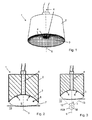
- Fig. 1 shows a perspective view of an embodiment of a handheld device 1 according to the invention.
- the handheld device 1 comprises an essentially cylindrical or cone-shaped body 2 having a front side at which a first surface 3 is provided.
- the first surface 3 is a curved surface with a concave shape.
- the first surface 3 is a spherically shaped surface which corresponds to the surface of a calotte.
- a plurality of detector elements 4 in particular ultrasonic detectors, is provided which forms a two-dimensional array of the detector elements 4 for detecting acoustic, in particular ultrasonic, waves emanating from an object under investigation (not shown) and generating according detector signals.
- the detector elements 4 are schematically represented by a grid-like arrangement of small squares. It is understood, however, that the individual detector elements can have various other shapes and/or sizes and/or orientations. For example, the detector elements can have a rectangular, subrectangular, polygonal or round shape. Preferably, piezoelectric elements are used for detection, wherein the strength of the detected signals can be optimized, i.e. increased, by maximizing the size of the individual detector elements 4 and minimizing the inter-element spacing between the detector elements 4.
- the total number and/or shape and/or size of the detector elements 4 is chosen such that they cover the first surface 3 entirely or at least a major part, in particular at least 70%, thereof. It is further preferred that the detector elements 4 adjoin each other.
- the first surface 3 or at least a major part thereof is formed by or constituted of the two-dimensional array of the detector elements 4.
- the elements 4 are arranged symmetrically around a center line 5 of the first surface 3 in order to maintain angular symmetry of the detector elements 4 with respect to the region of interest on or within the object.
- the elements 4 are arranged on concentric rings around the center line 5.
- a light guide 6 e.g. a fiber bundle, is arranged for guiding light generated by a light source, in particular a laser light source (not shown), to the handheld device 1 and for illuminating the object under investigation with light.
- a light guide 6 e.g. a fiber bundle
- the entire volume of interest within the imaged object is illuminated by laser pulses.
- the first surface 3 is a curved surface
- the invention is not limited to handheld devices comprising curved surfaces. Rather, in alternative embodiments of the invention the first surface 3 can be an essentially planar surface, wherein the above-mentioned elucidations regarding arrangements of detector elements 4 on curved surfaces apply to arrangements of the detector elements 4 on planar surfaces accordingly.
- Fig. 2 shows a cross-sectional view of a further embodiment of a handheld device 1 according to the invention.
- body 2 first surface 3, detector elements 4 and light guide 6 the elucidations given with respect to fig. 1 apply accordingly.
- a cover element 7 is provided by means of which the front side of the body 2 including the first surface 3 with the detector elements 4 is sealed such that a closed cavity 8 is formed.
- the cavity 8 is filled with a coupling medium 9 for acoustically coupling acoustic waves emanating from an object 10 to the detector elements 4 at the surface 3 and/or for optically coupling the light emerging from the light guide 6 to the object 10.
- the coupling medium is chosen such that its acoustic impedance and/or optical refractive index are similar to those of the object 10.
- the coupling medium 9 may consist of water or any other optically transparent medium with an acoustic impedance close to soft biological tissues.
- the cover element 7 is a mechanically flexible element, e.g. a membrane, a film or a foil of a material which is transparent for light emanating from the light guide 8.
- the cover element 7 encloses the acoustic coupling medium 9 and facilitates transmission of the optoacoustic waves while preventing a direct contact of the imaged object 10 with the coupling medium 9.
- the filled cover element 7 has a convex shape so that it can be easily placed onto an object 10 under investigation, irrespective of the spatial orientation of the handheld device 1. For example, reliable image acquisition is guaranteed both in vertical down orientation (shown in fig. 2 ) of the handheld device 1 or vertical up orientation as well as in any orientations in between, in particular slanted or horizontal orientations. Due to its mechanical flexibility and coupling medium filling, the membrane exhibits a cushion-like shape and behavior by means of which it easily adapts to various surface topologies of objects under investigation.
- the handheld device 1 can be moved relative to the object 10 under investigation, in particular to enable imaging of different regions of interest on or within the object 10.
- the cover element 7, in particular the membrane can be further coupled to the surface of the object 10 by means of an ultrasonic gel in order to further improve acoustic coupling and to facilitate a movement of the handheld device 1 on the surface of the object 10.
- the curvature and/or the size and/or the angular coverage of the first surface 3 is adapted to the size of the object 10 under investigation and/or the size of a region of interest on or within the object 10.
- angular coverage relates to an angular range within which acoustic waves emanating from a region of the object 10 are detected by the array of detector elements 4 of the handheld device 1.
- Dashed lines 12 and 13 which are orthogonal to the detector elements 4 located at a circumferential edge of the first surface 3, intersect at an angle ⁇ in an intersection point M, which is located in a region of interest ROI within the object 10.
- the angular coverage of the array of detector elements 4 corresponds to the angle ⁇ which is approximately 90° in the present example.
- the intersection point M corresponds to the center of a sphere having a radius r.
- the angular coverage and the radius r of the curvature of the first surface 3, on which the array of detector elements 4 is provided may vary depending on the particular imaging application.
- the main guiding principle is to acquire tomographic data from as many angles (i.e. projections) around the imaged volume as possible with the detection elements 4 located as close as possible to the imaged volume for better SNR (signal-to-noise ratio).
- SNR signal-to-noise ratio
- curvature and/or angular coverage of the first surface are preferably larger than in the case of a large object, e.g. a human body, where the curvature of the first surface is low or can be even planar.
- the imaged object 10 comprises a relatively small volume (e.g. 1 cm 3 ), which can be fully penetrated by the excitation laser light
- a spherical detection array fully enclosing the object from 360° is preferred.
- larger volumes are of interest while the excitation light can only effectively penetrate for several centimeters from one side, thus only limited-view acquisition is possible.
- imaging depth would play a crucial role in selecting the appropriate angular coverage and radius of curvature of the array.
- the effective field of view (i.e. angular coverage) of the array will have to be reduced to 90° or less.
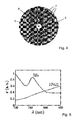
- Fig. 4 shows a planar projection of a bottom view on a further embodiment of a handheld device comprising a concave two-dimensional array of a plurality of detector elements 4.
- the array consists of 256 detector elements 4 with an angular coverage of 90°.
- the detector elements 4 are arranged on five concentric rings around the center line 5 of the array.
- the individual detector elements 4 are arranged and/or shaped such that they cover the first surface 3 entirely.
- the detector elements 4 are adjacent to each other, wherein each of the detector elements 4 borders on three or more neighboring detector elements 4.
- the light guide 6 is provided in a circularly shaped aperture around the center of the array of detector elements 4 the light guide 6 is provided.
- Ultrasound detector elements based on technologies like piezoelectric transducers (PZT) become directional as the size of the element increases. If such an element is placed in close proximity to the imaged object 10 (see fig. 2 ), it might only detect signals from a small region within the imaged volume, which will in turn reduce quality of the acquired tomographic data.
- the geometry of the array is designed such that each detector element 4 will detect acoustic waves from the entire volume of interest while taking into account also SNR considerations, which require minimal possible distance of the detector elements 4 to the object.
- raw optoacoustic data i.e. acoustic waves
- acoustic waves are simultaneously collected from all the detectors and processed in order to attain images in real time.
- image reconstruction several existing algorithms, e.g. back-projection algorithm, can be used.
- Image reconstruction from the detector signals corresponding to the detected acoustic waves preferably consists of recovering the distribution of optical absorbed energy, absorption coefficient as well as concentrations of specific chromophores within the imaged region.
- the raw optoacoustic signals are related to the optical absorption distribution H( r , ⁇ ) for the given laser wavelength ⁇ .
- Equation 1 is derived analytically and establishes the optoacoustic forward problem.
- Image reconstruction consists in solving the inverse problem, i.e., to estimate H ( r , ⁇ ) as a function of pressure waveforms p ( r , t ) acquired from multiple measurement locations.
- a common back-projection approximated analytical formula can be applied in order to calculate H ( r , ⁇ ).
- Equation 2 establishes a very fast reconstruction strategy, which is suitable for displaying the resulting images in real-time during the hand-held scanning procedure.
- Equation 1 is first discretized by considering a ROI consisting of a grid of points.
- the absorbed energy can be subsequently retrieved from Equation 4 by using variety of algorithms, for instance by inverting the model matrix A and multiplying it with the vector of the detected pressure variations p.
- the computational demands might be eased on by utilizing sparsity of the model matrix and applying more sophisticated algorithms, e.g.
- H sol arg min H ⁇ p m - AH ⁇ 2 + ⁇ T 2 ⁇ ⁇ H ⁇ 2 .
- Equation 5 can be then solved e.g. by means of an LSQR algorithm to attain distribution of the absorbed light energy.
- An alternative approach for handling large-scale inversions is by using multi-resolution methods, such as wavelet, wavelet packets or curvelet-based approaches, capable of separating the problem into a set of multiple smaller problems, each representing a different spatial and time resolution within the object/image.
- multi-resolution methods such as wavelet, wavelet packets or curvelet-based approaches
- tissue parameters e.g. blood oxygenation levels
- finding distribution of exogenously administered contrast agents based on optoacoustic measurements taken at multiple wavelengths.
- the endogenous optical absorption in biological tissues is mainly due to blood, i.e. the oxygenated (HbO 2 ) and deoxygenated (Hb) haemoglobin, whose molar extinction coefficients in the near infrared are depicted in fig. 5 .
Landscapes
- Life Sciences & Earth Sciences (AREA)
- Health & Medical Sciences (AREA)
- Physics & Mathematics (AREA)
- Heart & Thoracic Surgery (AREA)
- Molecular Biology (AREA)
- Pathology (AREA)
- Engineering & Computer Science (AREA)
- Biomedical Technology (AREA)
- Acoustics & Sound (AREA)
- Medical Informatics (AREA)
- Biophysics (AREA)
- Surgery (AREA)
- Animal Behavior & Ethology (AREA)
- General Health & Medical Sciences (AREA)
- Public Health (AREA)
- Veterinary Medicine (AREA)
- Ultra Sonic Daignosis Equipment (AREA)
- Investigating Or Analyzing Materials By The Use Of Ultrasonic Waves (AREA)
Abstract
Description
- The present invention relates to a handheld device and method for optoacoustic imaging of an object according to the independent claims.
- Optoacoustic imaging is based on the photoacoustic effect, according to which ultrasonic waves are generated due to absorption of electromagnetic radiation by an object, e.g. a biological tissue, and a subsequent thermoelastic expansion of the object.
-
US 6,102,857 discloses a tomographic imaging system in which optoacoustic signals are acquired by means of a plurality of acoustic sensors positioned along a spiral pattern on a spherical surface which is rotated relative to the sample. In alternative embodiments, rotatable or translatable planar arrangements of evenly spaced acoustic transducers are provided. Because of the required rotation or translation of the transducer arrangements relative to the sample while images are acquired and the need for according drive mechanisms, like motors, the set-up of the disclosed imaging system is complex and therefore not suitable for handheld applications. -
US 2010/0249570 A1 discloses a photoacoustic imaging apparatus comprising a box or a wand in which a sparse arrangement of transducer elements, which are spaced apart from one another, is provided. Because of the specific arrangement of transducer elements, it is not possible to efficiently collect three-dimensional optoacoustic images of the object without rotating or translating the apparatus while images are acquired. - The invention is based on the problem to provide a handheld device and a corresponding method allowing for improved optoacoustic imaging of an object, in particular allowing for an efficient collection of optoacoustic signals of the object without the need for rotating or translating the device while images are acquired.
- This problem is solved by the handheld device and the method according to the independent claims.
- The handheld device for optoacoustic imaging of an object according to the invention comprises an irradiation unit for irradiating the object with electromagnetic radiation, in particular light, and a detector unit for detecting acoustic, in particular ultrasonic, waves generated in the object upon irradiation with electromagnetic radiation and is characterized in that the detector unit comprises a two-dimensional array of a plurality of detector elements which are arranged along a first surface.
- The method for optoacoustic imaging of an object according to the invention comprises the steps of irradiating the object with electromagnetic radiation, in particular light, and detecting acoustic, in particular ultrasonic, waves generated in the object upon irradiation with electromagnetic radiation and is characterized in that the acoustic waves are detected by a two-dimensional array of a plurality of detector elements which are arranged along a first surface.
- The term "handheld device" within the meaning of the present invention relates to any optoacoustic imaging device which is adapted for being seized and held by clasping with fingers and/or a hand in order to position the handheld device onto an object under investigation and/or to move the handheld device by hand relative to the object under investigation, in particular by positioning it onto or moving it along an exterior surface of the object, e.g. the skin of a patient. The term "handheld device" also relates to optoacoustic imaging devices in which only a component thereof, in particular a handheld probe comprising the irradiation unit and/or the detector unit, is adapted for being seized and held by clasping with fingers and/or a hand for same purposes. Preferably, the size of a handheld device or a respective handheld probe within the meaning of the invention is less than 15 cm in width and/or depth and/or height. The term "handheld device" further relates to any optoacoustic imaging device which is designed for acquiring tomographic optoacoustic images at arbitrary orientations of the handheld device or handheld probe, respectively. For example, when acquiring images from the object, the orientation of the handheld device or probe can vary from a vertical up to a vertical down orientation including all orientations in between, in particular a horizontal orientation.
- According to an aspect of the invention, a handheld optoacoustic imaging probe is provided, in which a two-dimensional array of ultrasonic detectors is arranged on a, preferably spherical, surface. By this means, the individual detector elements can most efficiently collect signals corresponding to acoustic waves generated in the region of interest, which is preferably located around the center of a sphere. In contrast to systems and methods of the prior art, no movement, in particular no rotation, of the imaging probe and the object relative to each other is necessary in order to ensure an efficient collection of the acoustic waves emerging from the object. Since many imaging scenarios, such as imaging of large areas of human body, do not allow for a full tomographic access to the imaged area from all directions, the handheld device according to the invention is particularly advantageous as the generated acoustic waves are optimally collected from an as broad as possible range of angles, i.e. projections, around the imaged area located inside the object, in particular a living subject.
- According to another aspect of the invention, a control unit is provided for controlling the irradiation unit and the detector unit such that the irradiation unit irradiates the object with one or more pulses of electromagnetic radiation, in particular with illumination pulses, and the two-dimensionally arrayed detector elements of the detector unit simultaneously detect acoustic waves emanating from a plurality of locations and/or directions around the object after each pulse of electromagnetic radiation. Preferably, the control unit is designed for forming a three-dimensional image of the object on the basis of the acoustic waves, which are detected by the plurality of detector elements after a single pulse. Thus, by irradiating the object with a series of pulses of electromagnetic radiation an according series of three-dimensional images of the object is formed. Alternatively or additionally, the control unit is designed for forming a three-dimensional image of the object on the basis of acoustic waves which are detected upon a few, in particular up to ten, pulses of electromagnetic radiation. For example, a three-dimensional image is formed on the basis of acoustic waves, which are detected by the detector elements upon each pulse of two, three or four pulses. Due to the specific design and/or arrangement of the detector elements along the first surface according to the invention, a high-resolution three-dimensional image of the object can be obtained upon irradiation of the object by a single pulse or only a few pulses. The term "high-resolution" in this context preferably relates to an effective voxel number per imaged region of the object in the range between 100.000 and 1.000.000. This relatively high number of effective (resolution-limited) voxels can only be achieved if the space around the imaged object is densely populated with a high number of detection elements so that a full-view (well-posed) inverse (tomographic) problem has been formed. According to this aspect of the invention, high-resolution volumetric optoacoustic images of the object are acquired by means of an irradiation of the object with, e.g., a single laser pulse and simultaneous acquisition of optoacoustic responses, i.e. ultrasonic waves, from as many as possible locations and/or directions (projections) around the object. Since it usually takes on the order of a few tens of microseconds to acquire optoacoustic responses from typical objects or regions of a size of up to a few centimeters, images resulting from a single-pulse acquisition approach will be also significantly less affected by the object's motion, because of e.g. respiration or heartbeats, which in turn further improves spatial resolution and overall imaging accuracy.
- Multiple particular advantages exist therefore in achieving a three-dimensional real-time imaging according to the invention. First, dynamic biological processes, such as hemodynamic and neuronal responses or bio-distribution of molecular probes, can be monitored in the entire volume of interest. Second, motion artifacts (due to e.g. breathing or heartbeat of a living object), which could degrade the image quality when imaging living specimen, can be avoided. Finally, real-time performance can obviously reduce the time required for experiments or clinical measurements.
- In summary, by means of the handheld device and method according to the invention, a real-time three-dimensional imaging of an object is enabled which allows not only for imaging of dynamic phenomena in the object but also significantly reduces multiple motion-related and limited-view-related image artifacts and thus facilitates quantitative image acquisition. Thus, the invention allows for an improved optoacoustic imaging of an object.
- According to a preferred embodiment of the invention, the detector elements cover a major part of the first surface. Preferably, the number and/or dimension of the detector elements are chosen such that they cover at least 70%, preferably at least 85%, of the total area of the first surface. It is also preferred that the first surface is completely covered by the detector elements. Alternatively or additionally, the detector elements are arranged adjacently to each other, i.e. the detector elements adjoin each other and preferably cover the first surface for the most part or the first surface entirely. By this means, acoustic waves generated in the region of interest are detected in a very efficient way so that the detected acoustic response can be maximized, resulting in real-time performance and reduction or elimination of motion-related artifacts and other image inaccuracies resulting from e.g. limited-view tomographic geometries. The latter usually occur in tomographic optoacoustic systems that try to facilitate real-time imaging by e.g. reducing the tomographic problem into two dimensions by cylindrical focusing of the detection elements. This leads to substantial out-of-plane artefacts and quantification errors due to strong absorbers located outside the imaged plane (cross section). Moreover, anisotropic resolution is rendered due to the focusing of the detection elements while volumetric imaging is performed by scanning and cannot be done in real time.
- It is, moreover, preferred that the size of the detector elements is maximized and/or a space between the detector elements is minimized in order to improve signal-to-noise ratio and attain real-time performance without the need for signal averaging.
- It is particularly preferred that the detector elements are arranged on concentric rings along the, in particular curved, first surface. Thus, the efficiency and homogeneity of detection sensitivity among different elements is optimized by achieving an angular symmetry.
- Moreover, it is preferred that the first surface is a curved, in particular a spherically shaped, two-dimensional surface, in particular a concave surface and/or a calotte. By this means, the detector elements arranged on the first surface efficiently collect acoustic waves from the region upon or within the object, which is also located around a center of curvature of the curved two-dimensional surface. For example, if the curved two-dimensional surface is spherically shaped, the detector elements most efficiently collect acoustic waves from a region of the object located around the center of a sphere.
- According to a further embodiment of the invention, the first surface is a planar surface along which the two-dimensional array of detector elements is arranged. This embodiment is of particular advantage when images of larger volumes shall be acquired, as it ensures a particularly efficient collection of optoacoustic signals emerging from larger objects without the need for translating the device during the image acquisition process. Flat two-dimensional detection arrays are also simpler to manufacture.
- In yet another embodiment of the invention, the first surface is a convex surface or comprises a convex surface. By this means, the detection array arranged on the first surface efficiently collects acoustic waves from a wide angle around the array. This embodiment is advantageous for endoscopic imaging inside organs or body cavities, e.g. esophagus, blood vessels or gastrointestinal tract, where very limited tomographic access to the region of interest is possible.
- In another preferred embodiment of the invention, the handheld device comprises a cavity in which a coupling medium, in particular water, is accommodated, wherein the cavity is bounded by the first surface, along which the detector elements are arranged, and by at least one second surface. In particular, the second surface is a part of a cover element by means of which the cavity is sealed. In these embodiments, the cavity is formed by the first surface and the second surface, wherein the first surface is preferably formed or constituted by a continuous two-dimensional array of the, e.g. adjacently arranged, detector elements, and wherein the second surface is preferably formed or given by the cover element. By means of these provisions, the detector unit, i.e. the two-dimensional array of the plurality of detector elements, forms a part of the cavity in which the coupling medium is accommodated. Thus, no additional container for the coupling medium is necessary, which facilitates the handling of the handheld device considerably without adversely affecting its optimal real-time performance.
- It is preferred that the cover element is a mechanically flexible element, in particular a membrane or a film. The cover element is transparent for at least a part of the electromagnetic radiation. Preferably, at least a part of the cover element has a convex shape, in particular a cushion-like shape. In particular, the cover element is provided on a distal end of the handheld device. Moreover, the cover element is preferably arranged and/or designed such that at least a part of the cover element comes into contact with the object while images are acquired from the object. The transparent membrane is used to enclose the active detection surface while the volume inside the membrane is filled with matching fluid, e.g. water, in order to facilitate optimal acoustic coupling to the imaged object.
- Due to these provisions, the form of the cavity can - in the region of the cover element - be easily adapted to arbitrary forms of the objects under investigation so that the two-dimensional array of detector elements can be positioned in the respectively required manner relative to the region of interest on or within objects of different shapes. By this means, motion-related and/or out-of-plane artifacts can be reduced or avoided in a reliable and simple manner.
- Preferably, the cover element is acoustically and optically matched to the object for an optimal transmission of electromagnetic radiation, in particular light, and the generated acoustic waves. This helps avoiding or at least minimizing losses due to light reflections or reflections of acoustic waves at boundaries between the cover element and the object as well as between the cover element and the coupling medium.
- According to another preferred embodiment of the invention, the handheld device is designed such that it can be moved relative to the, preferably non-moving or substantially static, object, while images are acquired from the object. By this means, various regions of interest in the object can be tracked by acquiring their corresponding three-dimensional images in real-time.
- In further preferred embodiments of the invention the curvature and/or the size and/or the angular coverage of the first surface is arranged and/or depends on the size of the object and/or the size of a region of interest within the object. Alternatively or additionally, it is preferred that the size of the detector elements and/or the frequency response of the detector elements and/or the shape of the detector elements and/or the detection sensitivity of the detector elements and/or the directivity of the detector elements and/or the orientation of the normal to the surface of the detector elements is chosen such that an effective angular coverage of the detector elements around a region of interest is maximized. Preferably, one or more of these features or parameters are chosen such that the effective angular coverage of the detector elements around a region of interest, their detection bandwidth and signal-to-noise-ratio are maximized. Hereby it is ensured that for any kind of objects, e.g. large areas of the human body or small tissue specimen, acoustic waves are detected by the two-dimensional array of detector elements in the broadest possible solid angle range, i.e. broadest possible range of angles (projections) around the imaged area of the object. Furthermore, by optimizing the shape of the detection surface, the orientation of individual detection elements toward the imaged region can be optimized or the distance of said elements from said region minimized in order to increase the detected optoacoustic responses from all the elements and minimize effects of acoustic refractions and surface mismatches.
- From the point of view of pure mathematical tomographic reconstruction problem, it is advantageous to have as many discrete detection elements as possible with the broadest possible coverage around the imaged region in order to effectively resemble a full-view point-detector problem and achieve best possible image quality, spatial resolution and quantification capabilities. On the other hand, increasing the number of elements will correspondingly decrease their size, which will in turn adversely affect the signal-to-noise performance, subsequently increase image noise and, as a result, reduce imaging speed and achievable imaging depth. Thus, the total number of the detection elements is chosen such that both image quality and imaging speed are optimized for the given object, tomographic geometry and imaging requirements of the particular application (imaging speed, quantification, resolution etc).
- Moreover, it is preferred that the irradiation unit comprises a light emitting element and/or a light guide, in particular a fiber bundle, which is fed through at least one aperture provided in the first surface. Preferably, the fiber bundle is inserted into an aperture or a hole located in the center of the detection array. This is a simple way to provide an effective irradiation of the imaged region, in particular when the first surface has a concave or spherical shape. For implementations involving flat or convex detection surfaces, for which larger volumes need to be illuminated, it is particularly advantageous that the light emitting element and/or light guide is provided in several apertures in the first surface.
- In summary, the preferred embodiments set forth above relate to a detection of acoustic waves with an array of ultrasonic sensors distributed on a spherical surface (or otherwise a surface having shape optimized to the shape and size of the imaged object), which significantly reduces out-of-plane artifacts and helps achieving close to isotropic imaging resolution as well. As the normal to the elements is directed towards the center of the curvature, in particular a sphere, all of the detection elements lying on the curved array efficiently collect optoacoustic signals generated in this region. The optimal orientation of the elements towards the imaged region also maximizes the effective angular coverage of the array, and consequently reduces the effects of limited-view reconstructions and out-of-plane artifacts. Since the magnitude of generated optoacoustic signals is typically very low, especially from deep tissue areas suffering from significant light attenuation, special attention needs to be put regarding detection sensitivity of the individual detection elements. For instance, if detection is performed using piezoelectric elements, their size is increased to guarantee the best possible signal-to-noise ratio.
- Of particular importance for quantitative optoacoustic imaging is the effective frequency bandwidth of the detection elements. Broadband detection can be facilitated by using broadband piezoelectric technologies, such as polyvinylidene difluoride (pVDF) films. In order to maximize bandwidth, optical detection of optoacoustic responses is preferably employed, e.g. using Fabry-Perot films, fiber Brag gratings, ring-shaped or spherical resonators. For the optical detection approaches, the detection sensitivity might be further increased by e.g. increasing quality factor of the corresponding resonant structure.
- Moreover, illumination is performed by means of a fiber bundle inserted in a cylindrical cavity provided in the two-dimensional array of detector elements. In this way, the optical energy delivered to the imaging region is maximized, contrary to linear arrays with lateral illumination for which only scattered photons provide excitation at locations corresponding to a high-sensitivity of the ultrasonic sensors.
- Moreover, the handheld approach including respective preferred embodiments is as well an important aspect of the invention as it allows convenient handling of pre-clinical experiments and clinical measurements. The preferred handheld device uses a transparent membrane in order to allow efficient coupling of opto-acoustically generated waves to the ultrasonic detector elements while avoiding direct contact of the imaged object with the coupling medium.
- The handheld arrangement can be optimized with respect to additional requirements. For example, in many cases the measurement head is held by hand and not fixed relative to the object, thus the images must be acquired in real time without signal averaging (single pulse acquisition) in order to avoid motion artifacts. Thereby, the arrangement of the illumination set-up and the ultrasonic detectors is crucial. Specifically, maximal detection sensitivity and appropriate orientation of the ultrasonic transducers (maximal tomographic coverage) are essential to efficiently collect the optoacoustic signals generated in the imaging region and ensure real-time performance without the need for signal averaging in order to improve signal-to-noise performance.
- Yet, in many cases, no full tomographic access to the object is possible, therefore image reconstruction is challenged by the limited-view problem (only a limited number of positions around the object or the imaged region are accessible). The present three-dimensional acquisition and reconstruction approach helps to considerably mitigate image artifacts associated with those problems as well, helping to make the images more quantitative and identify the correct properties of structures within tissues with respect to e.g. their shape, size, optical absorption and spectral characteristics.
- The irradiation unit may use various types of electromagnetic radiation in order to induce an optoacoustic or thermoacoustic effect in the imaged object. This includes short-pulsed lasers, pulsed sources in the microwave and radiofrequency (RF) bands, intensity-modulated light or RF sources,
- In another particularly preferred embodiment, a control unit for controlling the irradiation unit and the detector unit is provided such that the irradiation unit illuminates the object with pulsed illumination light and the illumination of the object and the detection of acoustic waves are repeated at least twice with different wavelengths of the illumination light. Additionally or alternatively, the detector elements are controlled such that acoustic waves are detected simultaneously by all of the detector elements. Preferably, the handheld device is arranged such that a three-dimensional image of the object is formed after each illumination pulse, i.e. in real time, without moving the device with respect to the object. This technique, which is called multispectral optoacoustic tomography (MSOT), is very advantageous in optoacoustic imaging of biological tissues as it provides a unique combination of high spatial resolution and rich contrast based on spectrally dependent absorption of light. MSOT enables to simultaneously render images of anatomical, functional and molecular contrast by exciting tissues at several optical wavelengths. Therefore, if the illumination wavelength is further swept in a fast and reliable manner, these embodiments will allow for an acquisition of real-time multispectral optoacoustic tomographic images of the object by means of which a highly sensitive visualization of functional and molecular bio-markers in living tissues with unprecedented anatomical, functional and molecular imaging capabilities is achieved. This will effectively attain a 5D imaging system capable of simultaneously delivering volumetric (3D), time-resolved (4D) and spectrally-enriched (5D) data.
- Further advantages, features and examples of the present invention will be apparent from the following description of following figures:
- Fig. 1
- shows a perspective view of an embodiment of a handheld device according to the invention;
- Fig. 2
- shows a cross-sectional view of a further embodiment of a handheld device according to the invention;
- Fig. 3
- shows a cross-sectional view of the embodiment of
fig. 2 for illustrating the angle of coverage; - Fig. 4
- shows a planar projection of a further embodiment of a handheld device according to the invention comprising a curved two-dimensional array of a plurality of detector elements; and
- Fig. 5
- shows a spectrum of molar extinction coefficient of oxygenated (HbO2) and deoxygenated (Hb) haemoglobin in the near-infrared.
-
Fig. 1 shows a perspective view of an embodiment of ahandheld device 1 according to the invention. Thehandheld device 1 comprises an essentially cylindrical or cone-shapedbody 2 having a front side at which afirst surface 3 is provided. In the embodiment shown, thefirst surface 3 is a curved surface with a concave shape. Preferably, thefirst surface 3 is a spherically shaped surface which corresponds to the surface of a calotte. - On the first surface 3 a plurality of
detector elements 4, in particular ultrasonic detectors, is provided which forms a two-dimensional array of thedetector elements 4 for detecting acoustic, in particular ultrasonic, waves emanating from an object under investigation (not shown) and generating according detector signals. - In the example given in
fig. 1 , thedetector elements 4 are schematically represented by a grid-like arrangement of small squares. It is understood, however, that the individual detector elements can have various other shapes and/or sizes and/or orientations. For example, the detector elements can have a rectangular, subrectangular, polygonal or round shape. Preferably, piezoelectric elements are used for detection, wherein the strength of the detected signals can be optimized, i.e. increased, by maximizing the size of theindividual detector elements 4 and minimizing the inter-element spacing between thedetector elements 4. - Preferably, the total number and/or shape and/or size of the
detector elements 4 is chosen such that they cover thefirst surface 3 entirely or at least a major part, in particular at least 70%, thereof. It is further preferred that thedetector elements 4 adjoin each other. By this means, thefirst surface 3 or at least a major part thereof is formed by or constituted of the two-dimensional array of thedetector elements 4. - Preferably, the
elements 4 are arranged symmetrically around acenter line 5 of thefirst surface 3 in order to maintain angular symmetry of thedetector elements 4 with respect to the region of interest on or within the object. In particular, theelements 4 are arranged on concentric rings around thecenter line 5. - At the center of the two-dimensional array of
detector elements 4, in particular around thecenter line 5 of thefirst surface 3, an aperture is provided in which alight guide 6, e.g. a fiber bundle, is arranged for guiding light generated by a light source, in particular a laser light source (not shown), to thehandheld device 1 and for illuminating the object under investigation with light. Preferably, the entire volume of interest within the imaged object is illuminated by laser pulses. - Although in this embodiment of the invention the
first surface 3 is a curved surface, the invention is not limited to handheld devices comprising curved surfaces. Rather, in alternative embodiments of the invention thefirst surface 3 can be an essentially planar surface, wherein the above-mentioned elucidations regarding arrangements ofdetector elements 4 on curved surfaces apply to arrangements of thedetector elements 4 on planar surfaces accordingly. -
Fig. 2 shows a cross-sectional view of a further embodiment of ahandheld device 1 according to the invention. Regardingbody 2,first surface 3,detector elements 4 andlight guide 6 the elucidations given with respect tofig. 1 apply accordingly. - At a distal end of the
handheld device 1 corresponding to the front side of the body 2 acover element 7 is provided by means of which the front side of thebody 2 including thefirst surface 3 with thedetector elements 4 is sealed such that aclosed cavity 8 is formed. Thecavity 8 is filled with acoupling medium 9 for acoustically coupling acoustic waves emanating from anobject 10 to thedetector elements 4 at thesurface 3 and/or for optically coupling the light emerging from thelight guide 6 to theobject 10. The coupling medium is chosen such that its acoustic impedance and/or optical refractive index are similar to those of theobject 10. In order to avoid reflections and loss of signal, thecoupling medium 9 may consist of water or any other optically transparent medium with an acoustic impedance close to soft biological tissues. - The
cover element 7 is a mechanically flexible element, e.g. a membrane, a film or a foil of a material which is transparent for light emanating from thelight guide 8. Thecover element 7 encloses theacoustic coupling medium 9 and facilitates transmission of the optoacoustic waves while preventing a direct contact of the imagedobject 10 with thecoupling medium 9. In the embodiment shown, the filledcover element 7 has a convex shape so that it can be easily placed onto anobject 10 under investigation, irrespective of the spatial orientation of thehandheld device 1. For example, reliable image acquisition is guaranteed both in vertical down orientation (shown infig. 2 ) of thehandheld device 1 or vertical up orientation as well as in any orientations in between, in particular slanted or horizontal orientations. Due to its mechanical flexibility and coupling medium filling, the membrane exhibits a cushion-like shape and behavior by means of which it easily adapts to various surface topologies of objects under investigation. - During image acquisition, the
handheld device 1 can be moved relative to theobject 10 under investigation, in particular to enable imaging of different regions of interest on or within theobject 10. Moreover, thecover element 7, in particular the membrane, can be further coupled to the surface of theobject 10 by means of an ultrasonic gel in order to further improve acoustic coupling and to facilitate a movement of thehandheld device 1 on the surface of theobject 10. - The curvature and/or the size and/or the angular coverage of the
first surface 3 is adapted to the size of theobject 10 under investigation and/or the size of a region of interest on or within theobject 10. - In the sense of the present invention, the term "angular coverage" relates to an angular range within which acoustic waves emanating from a region of the
object 10 are detected by the array ofdetector elements 4 of thehandheld device 1. - This is illustrated by the example shown in
fig. 3 . Dashedlines detector elements 4 located at a circumferential edge of thefirst surface 3, intersect at an angle α in an intersection point M, which is located in a region of interest ROI within theobject 10. The angular coverage of the array ofdetector elements 4 corresponds to the angle α which is approximately 90° in the present example. Because thefirst surface 3 is a spherical surface in this embodiment, the intersection point M corresponds to the center of a sphere having a radius r. - The angular coverage and the radius r of the curvature of the
first surface 3, on which the array ofdetector elements 4 is provided, may vary depending on the particular imaging application. The main guiding principle is to acquire tomographic data from as many angles (i.e. projections) around the imaged volume as possible with thedetection elements 4 located as close as possible to the imaged volume for better SNR (signal-to-noise ratio). For example, in the case of a small object, e.g. a small animal or a tissue sample, curvature and/or angular coverage of the first surface are preferably larger than in the case of a large object, e.g. a human body, where the curvature of the first surface is low or can be even planar. - For instance, if the imaged
object 10 comprises a relatively small volume (e.g. 1 cm3), which can be fully penetrated by the excitation laser light, a spherical detection array fully enclosing the object from 360° is preferred. Clearly, in a clinical imaging scenario larger volumes are of interest while the excitation light can only effectively penetrate for several centimeters from one side, thus only limited-view acquisition is possible. In this case, imaging depth would play a crucial role in selecting the appropriate angular coverage and radius of curvature of the array. While for superficial targets it would be beneficial and possible to enclose almost 180° around the imaged area with thedetector elements 4 arranged along a hemi-spherical array, for deep tissue targets the effective field of view (i.e. angular coverage) of the array will have to be reduced to 90° or less. -
Fig. 4 shows a planar projection of a bottom view on a further embodiment of a handheld device comprising a concave two-dimensional array of a plurality ofdetector elements 4. In the given example, the array consists of 256detector elements 4 with an angular coverage of 90°. Thedetector elements 4 are arranged on five concentric rings around thecenter line 5 of the array. Preferably, theindividual detector elements 4 are arranged and/or shaped such that they cover thefirst surface 3 entirely. As obvious from this representation, thedetector elements 4 are adjacent to each other, wherein each of thedetector elements 4 borders on three or moreneighboring detector elements 4. In a circularly shaped aperture around the center of the array ofdetector elements 4 thelight guide 6 is provided. - An additional consideration must be given to the size of the
detector elements 4. Ultrasound detector elements based on technologies like piezoelectric transducers (PZT) become directional as the size of the element increases. If such an element is placed in close proximity to the imaged object 10 (seefig. 2 ), it might only detect signals from a small region within the imaged volume, which will in turn reduce quality of the acquired tomographic data. Preferably, the geometry of the array is designed such that eachdetector element 4 will detect acoustic waves from the entire volume of interest while taking into account also SNR considerations, which require minimal possible distance of thedetector elements 4 to the object. - As already set forth above, raw optoacoustic data, i.e. acoustic waves, are simultaneously collected from all the detectors and processed in order to attain images in real time. For image reconstruction several existing algorithms, e.g. back-projection algorithm, can be used.
- In the following, a novel three-dimensional model-based approach will be described, which is particularly suitable for accurate extraction of absorption maps from data acquired with the present handheld device or method. Spectral fitting of the images retrieved at several wavelengths is used to provide concentration maps of intrinsic tissue chromophores (such as oxygenated and deoxygenated haemoglobin) as well as extrinsically administered contrast agents.
- Image reconstruction from the detector signals corresponding to the detected acoustic waves preferably consists of recovering the distribution of optical absorbed energy, absorption coefficient as well as concentrations of specific chromophores within the imaged region.
- In general, the raw optoacoustic signals are related to the optical absorption distribution H( r ,λ) for the given laser wavelength λ. Thus, the generated acoustic pressure p(r,t) for a given position r and instant t is given as a function of H(r, λ) by the Poisson-type integral as

-
Equation 1 is derived analytically and establishes the optoacoustic forward problem. Image reconstruction consists in solving the inverse problem, i.e., to estimate H(r, λ) as a function of pressure waveforms p(r,t) acquired from multiple measurement locations. A common back-projection approximated analytical formula can be applied in order to calculate H(r, λ). In its discrete form it is given by
Equation 2 establishes a very fast reconstruction strategy, which is suitable for displaying the resulting images in real-time during the hand-held scanning procedure. - However, approximations in deriving back-projection formulae may lead to quantitative errors in the reconstructed images, which is particularly important for determining accurate maps of chromophore distribution and other metrics such as blood oxygenation levels.
- A different reconstruction approach, also termed the model-based inversion, consists in a numerical inversion of
Equation 1. For this,Equation 1 is first discretized by considering a ROI consisting of a grid of points. In this way, the pressure at a point r i band at an instant tj can be expressed as a linear combination of the optical absorption at the points of the grid r' k , i.e.,
Equation 3 can be expressed in a matrix form as
Equation 4 by using variety of algorithms, for instance by inverting the model matrix A and multiplying it with the vector of the detected pressure variations p. In case of very large model matrices, such as those obtained for volumetric time-resolved data, the computational demands might be eased on by utilizing sparsity of the model matrix and applying more sophisticated algorithms, e.g. regularization-assisted singular value decomposition (SVD), Moore-Penrose pseudo-inverse or minimization of the least square difference between the theoretical pressure and the measured pressure p m, i.e.,
- The term λT corresponds to the regularization parameter, which is needed to obtain a representative (reasonable) solution.
Equation 5 can be then solved e.g. by means of an LSQR algorithm to attain distribution of the absorbed light energy. - An alternative approach for handling large-scale inversions is by using multi-resolution methods, such as wavelet, wavelet packets or curvelet-based approaches, capable of separating the problem into a set of multiple smaller problems, each representing a different spatial and time resolution within the object/image.
- There are several advantages in using the exact model-based reconstruction approach versus approximated analytical formulas, such as back-projection. First, as mentioned, it avoids inaccuracies involved with analytical approximation formulas, thus improves quantification performance. Second, it allows seamless inclusion of multiple important experimental parameters into the numerical model, such as the particular detection geometry, shape of the individual detection elements and their frequency response, the light pattern upon and within the imaged object, and acoustic heterogeneities in the object. This, in turn, helps to improve quantification and avoid image blurring due to incorrect modeling assumptions. Third, it allows efficient implementation of the said multi-resolution methods for achieving a tremendous acceleration of the reconstruction procedures and the corresponding imaging speed.
- For functional and molecular imaging applications, of particular interest is also determining functional tissue parameters (e.g. blood oxygenation levels) and finding distribution of exogenously administered contrast agents based on optoacoustic measurements taken at multiple wavelengths.
- For instance, the endogenous optical absorption in biological tissues is mainly due to blood, i.e. the oxygenated (HbO2) and deoxygenated (Hb) haemoglobin, whose molar extinction coefficients in the near infrared are depicted in
fig. 5 . - Distribution of the absorbed light energy (in arbitrary units) for a set of wavelengths λi , with i=1,..,n, is then given by

Equation 6 can be expressed in a matrix form as
- The concentration of oxygenated and deoxygenated haemoglobin can be determined by least-square spectral fitting of the images taken at the n measured wavelengths. This is done with the Moore-Penrose pseudoinverse as

- Then, the distribution of the oxygenation level SO 2(r) is no longer affected by the illumination light fluence variations and is explicitly given by

- Due to high level of heterogeneity of realistic biological tissues, the above simple assumptions might however lead to image inaccuracies and lack of quantification. For instance, spatial variations in light fluence due to attenuation are preferably compensated by using e.g. numerical modeling of light propagation in tissues, analytical correction functions or blind correction methods that do not use any models of light propagation but instead sparsely decompose the fluence from the optical absorption coefficient. Another complexity might arise from the lack of precise knowledge about the spectrum of different chrmophores in tissue or otherwise spectrally-dependent light attenuation within the object. In this case, methods based on the ratios between images acquired at different wavelengths, are applied in order to reduce the effect of spectrally-dependent attenuation. In addition, blind spectral methods, such as principal component analysis (PCA) and independent component analysis (ICA), are used in order to retrieve both the spatial distribution maps of the different chromophores as well as their spectral dependence curves.
Claims (18)
- Handheld device (1) for optoacoustic imaging of an object (10) comprising- an irradiation unit (6) for irradiating the object (10) with electromagnetic radiation, in particular light, and- a detector unit (3, 4) for detecting acoustic, in particular ultrasonic, waves which are generated in the object (10) upon irradiation with electromagnetic radiation,characterized in that
the detector unit (3, 4) comprises a two-dimensional array of a plurality of detector elements (4) which are arranged along a first surface (3). - Handheld device (1) according to claim 1, wherein the first surface (3) is a curved surface, in particular a concave or convex surface, or a planar surface.
- Handheld device (1) according to one of the foregoing claims, wherein the detector elements (4) cover a major part of the first surface (3).
- Handheld device (1) according to one of the foregoing claims, wherein the detector elements (4) are arranged adjacently to each other.
- Handheld device (1) according to one of the foregoing claims, wherein the detector elements (4) are arranged on concentric rings along the, in particular curved, first surface (3).
- Handheld device (1) according to one of the foregoing claims comprising a cavity in which a coupling medium (9), in particular water, is accommodated, wherein the cavity is bounded by the first surface (3), along which the detector elements (4) are arranged, and by at least one second surface.
- Handheld device (1) according to claim 6, wherein the second surface is a part of a cover element (7) by means of which the cavity is sealed.
- Handheld device (1) according to claim 7, wherein the cover element (7) is a mechanically flexible element, in particular a membrane or a film.
- Handheld device (1) according to claim 7 or 8, wherein the cover element is acoustically and optically matched to the object (10) for an optimal transmission of electromagnetic radiation, in particular light, and the generated acoustic waves.
- Handheld device (1) according to one of claims 7 to 9, wherein at least a part of the cover element (7) has a convex shape, in particular a cushion-like shape.
- Handheld device (1) according to one of claims 7 to 10, wherein the cover element (1) is arranged and/or designed such that at least a part of the cover element (7) comes into contact with the object (10) while images are acquired from the object (10).
- Handheld device (1) according to one of the foregoing claims, wherein the handheld device (1) is designed such that it can be moved relative to the, preferably stationary, object (10) while images are acquired from the object (10).
- Handheld device (1) according to one of the foregoing claims, wherein the curvature and/or the size and/or the angular coverage (α) of the first surface (3) depends on the shape of the surface of the object (10) and/or the size of the object (10) and/or a region of interest within the object (10).
- Handheld device (1) according to one of the foregoing claims, wherein the size of the detector elements (4) and/or the frequency response of the detector elements (4) and/or the shape of the detector elements (4) and/or the detection sensitivity of the detector elements (4) and/or the orientation of the normal (12, 13) to the surface of the detector elements (4) is chosen such that an effective angular coverage (α) of the detector elements (4) around a region of interest (ROI) is maximized.
- Handheld device (1) according to one of the foregoing claims, wherein the irradiation unit comprises a light emitting element and/or a light guide (6), in particular a fiber bundle, which is fed through at least one aperture provided in the first surface (3).
- Handheld device (1) according to one of the foregoing claims comprising a control unit for controlling the irradiation unit (6) and the detector unit (3, 4) such that the irradiation unit (6) illuminates the object (10) with pulsed illumination light and the illumination of the object (10) and the detection of acoustic waves are repeated at least twice with different wavelengths of the illumination light.
- Handheld device according to claim 16 arranged such that a three-dimensional image of the object (10) is formed after each illumination pulse, in particular in real time, without moving the device (1) with respect to the object (10).
- Method for optoacoustic imaging of an object (10) by- irradiating the object (10) with electromagnetic radiation, in particular light, and- detecting acoustic, in particular ultrasonic, waves which are generated in the object (10) upon irradiation with electromagnetic radiation,characterized in that
the acoustic waves are detected by a two-dimensional array of a plurality of detector elements (4) which are arranged along a first surface (3).
Priority Applications (6)
| Application Number | Priority Date | Filing Date | Title |
|---|---|---|---|
| EP12008269.8A EP2742853B1 (en) | 2012-12-11 | 2012-12-11 | Handheld device and method for volumetric real-time optoacoustic imaging of an object |
| JP2013255321A JP2014113496A (en) | 2012-12-11 | 2013-12-10 | Handheld device and method for volumetric realtime optoacoustic imaging of object |
| US14/102,250 US20140163353A1 (en) | 2012-12-11 | 2013-12-10 | Handheld device and method for volumetric real-time optoacoustic imaging of an object |
| CN201310676703.1A CN103860141A (en) | 2012-12-11 | 2013-12-11 | Handheld device and method for volumetric real-time optoacoustic imaging of an object |
| JP2015206017A JP6174656B2 (en) | 2012-12-11 | 2015-10-20 | Hand-held device and method for stereoscopic real-time photoacoustic imaging of an object |
| US17/384,102 US20210345883A1 (en) | 2012-12-11 | 2021-07-23 | Handheld device and method for volumetric reat-time optoacoustic imaging of an object |
Applications Claiming Priority (1)
| Application Number | Priority Date | Filing Date | Title |
|---|---|---|---|
| EP12008269.8A EP2742853B1 (en) | 2012-12-11 | 2012-12-11 | Handheld device and method for volumetric real-time optoacoustic imaging of an object |
Publications (2)
| Publication Number | Publication Date |
|---|---|
| EP2742853A1 true EP2742853A1 (en) | 2014-06-18 |
| EP2742853B1 EP2742853B1 (en) | 2022-03-23 |
Family
ID=47598550
Family Applications (1)
| Application Number | Title | Priority Date | Filing Date |
|---|---|---|---|
| EP12008269.8A Active EP2742853B1 (en) | 2012-12-11 | 2012-12-11 | Handheld device and method for volumetric real-time optoacoustic imaging of an object |
Country Status (4)
| Country | Link |
|---|---|
| US (2) | US20140163353A1 (en) |
| EP (1) | EP2742853B1 (en) |
| JP (2) | JP2014113496A (en) |
| CN (1) | CN103860141A (en) |
Cited By (2)
| Publication number | Priority date | Publication date | Assignee | Title |
|---|---|---|---|---|
| US20200069189A1 (en) * | 2018-09-04 | 2020-03-05 | Ithera Medical Gmbh | Probe, system and method for optoacoustic imaging of an object |
| US11684271B2 (en) | 2020-03-05 | 2023-06-27 | Welch Allyn, Inc. | Wearable device for sensing vital signs |
Families Citing this family (19)
| Publication number | Priority date | Publication date | Assignee | Title |
|---|---|---|---|---|
| CA2731409C (en) | 2008-07-25 | 2016-01-05 | Daniel Razansky | Quantitative multi-spectral opto-acoustic tomography (msot) of tissue biomarkers |
| EP3173781B8 (en) * | 2015-11-25 | 2024-06-12 | Xarion Laser Acoustics GmbH | Airborne ultrasound testing system for a test object |
| EP2742854B1 (en) | 2012-12-11 | 2021-03-10 | iThera Medical GmbH | Handheld device and method for tomographic optoacoustic imaging of an object |
| JP6223129B2 (en) * | 2013-10-31 | 2017-11-01 | キヤノン株式会社 | Subject information acquisition apparatus, display method, subject information acquisition method, and program |
| US20160022150A1 (en) * | 2014-07-24 | 2016-01-28 | Canon Kabushiki Kaisha | Photoacoustic apparatus |
| JP2016048207A (en) * | 2014-08-28 | 2016-04-07 | プレキシオン株式会社 | Photoacoustic imaging apparatus |
| EP3242586A1 (en) | 2015-01-07 | 2017-11-15 | C/o Canon Kabushiki Kaisha | Photoacoustic apparatus, image display method, and program |
| EP3103396B1 (en) | 2015-06-10 | 2018-10-24 | Helmholtz Zentrum München Deutsches Forschungszentrum für Gesundheit und Umwelt GmbH | Device and method for hybrid optoacoustic tomography and ultrasonography |
| JP2017047180A (en) * | 2015-09-04 | 2017-03-09 | キヤノン株式会社 | A probe array, and an acoustic wave measuring apparatus including the probe array. |
| US10471159B1 (en) | 2016-02-12 | 2019-11-12 | Masimo Corporation | Diagnosis, removal, or mechanical damaging of tumor using plasmonic nanobubbles |
| ES3046787T3 (en) * | 2018-03-09 | 2025-12-02 | Univ Muenchen Tech | Sensor for tissue measurements |
| JP7144805B2 (en) * | 2018-08-21 | 2022-09-30 | キヤノン株式会社 | Image processing device, image processing method, program |
| CN119732655A (en) * | 2018-09-19 | 2025-04-01 | 深圳迈瑞生物医疗电子股份有限公司 | A photoacoustic dual-mode imaging probe |
| WO2020065726A1 (en) * | 2018-09-25 | 2020-04-02 | オリンパス株式会社 | Photoacoustic imaging device |
| EP3677907A1 (en) * | 2019-01-04 | 2020-07-08 | Xarion Laser Acoustics GmbH | Device and method for testing a test object |
| US12066426B1 (en) | 2019-01-16 | 2024-08-20 | Masimo Corporation | Pulsed micro-chip laser for malaria detection |
| US12207901B1 (en) | 2019-08-16 | 2025-01-28 | Masimo Corporation | Optical detection of transient vapor nanobubbles in a microfluidic device |
| CN112603263B (en) * | 2020-12-14 | 2023-09-05 | 华南师范大学 | Palm photoacoustic imaging device and method |
| US20250072761A1 (en) * | 2023-09-05 | 2025-03-06 | Qualcomm Incorporated | Multispectral photoacoustic devices |
Citations (9)
| Publication number | Priority date | Publication date | Assignee | Title |
|---|---|---|---|---|
| US6102857A (en) | 1996-10-04 | 2000-08-15 | Optosonics, Inc. | Photoacoustic breast scanner |
| US20020193678A1 (en) * | 2001-06-19 | 2002-12-19 | Kruger Robert A. | Thermoacoustic tissue scanner |
| US20060184042A1 (en) * | 2005-01-22 | 2006-08-17 | The Texas A&M University System | Method, system and apparatus for dark-field reflection-mode photoacoustic tomography |
| US7515948B1 (en) * | 2003-09-12 | 2009-04-07 | Ornim Inc. | Photoacoustic analyzer of region of interest in a human body |
| US20100249570A1 (en) | 2007-12-12 | 2010-09-30 | Carson Jeffrey J L | Three-dimensional photoacoustic imager and methods for calibrating an imager |
| WO2011072198A2 (en) * | 2009-12-10 | 2011-06-16 | The Board Of Regents Of The University Of Texas System | Optoacoustic / photoacoustic / acoustic imaging system using probe beam deflection |
| WO2011137385A1 (en) * | 2010-04-30 | 2011-11-03 | Visualsonics Inc. | Photoacoustic transducer and imaging system |
| US20120123256A1 (en) * | 2009-06-29 | 2012-05-17 | Helmholtz Zentrum München Deutsches Forschungszentrum Für Gesundheit Und Umwelt (Gmbh) | Thermoacoustic imaging with quantitative extraction of absorption map |
| WO2012150721A1 (en) * | 2011-05-02 | 2012-11-08 | Canon Kabushiki Kaisha | Light irradiating apparatus, control method therefor, and object information acquiring apparatus |
Family Cites Families (17)
| Publication number | Priority date | Publication date | Assignee | Title |
|---|---|---|---|---|
| US4180792A (en) * | 1978-03-09 | 1979-12-25 | General Electric Company | Transmit-receive transducer array and ultrasonic imaging system |
| EP0111386B1 (en) * | 1982-10-26 | 1987-11-19 | University Of Aberdeen | Ultrasound hyperthermia unit |
| JPH0761336B2 (en) * | 1987-08-05 | 1995-07-05 | 株式会社東芝 | Ultrasonic treatment applicator |
| JPH03151952A (en) * | 1989-11-08 | 1991-06-28 | Matsushita Electric Ind Co Ltd | Ultrasonic therapy device |
| JP3386488B2 (en) * | 1992-03-10 | 2003-03-17 | 株式会社東芝 | Ultrasound therapy equipment |
| JP2004351023A (en) * | 2003-05-30 | 2004-12-16 | Olympus Corp | Photoacoustic probe |
| IL166408A0 (en) * | 2005-01-20 | 2006-01-15 | Ultraview Ltd | Combined 2d pulse-echo ultrasound and optoacousticsignal for glaucoma treatment |
| US20080228073A1 (en) * | 2007-03-12 | 2008-09-18 | Silverman Ronald H | System and method for optoacoustic imaging of peripheral tissues |
| US9528966B2 (en) * | 2008-10-23 | 2016-12-27 | Washington University | Reflection-mode photoacoustic tomography using a flexibly-supported cantilever beam |
| JP2010125260A (en) * | 2008-12-01 | 2010-06-10 | Canon Inc | Biological testing apparatus |
| JP2012525233A (en) * | 2009-05-01 | 2012-10-22 | ビジュアルソニックス インコーポレイテッド | System and method for photoacoustic imaging |
| EP2332614A1 (en) * | 2009-12-10 | 2011-06-15 | Theraclion SAS | Ultrasound treatment device |
| JP5448918B2 (en) * | 2010-02-24 | 2014-03-19 | キヤノン株式会社 | Biological information processing device |
| CN201624671U (en) * | 2010-04-01 | 2010-11-10 | 江西科技师范学院 | A device for three-dimensional photoacoustic imaging of biological tissue |
| KR101251939B1 (en) * | 2010-12-17 | 2013-04-08 | 이재웅 | Golf practice golf mat |
| JP5939786B2 (en) * | 2011-02-10 | 2016-06-22 | キヤノン株式会社 | Acoustic wave acquisition device |
| JP5469113B2 (en) * | 2011-02-24 | 2014-04-09 | 富士フイルム株式会社 | Probe unit for photoacoustic analysis and photoacoustic analyzer |
-
2012
- 2012-12-11 EP EP12008269.8A patent/EP2742853B1/en active Active
-
2013
- 2013-12-10 US US14/102,250 patent/US20140163353A1/en not_active Abandoned
- 2013-12-10 JP JP2013255321A patent/JP2014113496A/en not_active Withdrawn
- 2013-12-11 CN CN201310676703.1A patent/CN103860141A/en active Pending
-
2015
- 2015-10-20 JP JP2015206017A patent/JP6174656B2/en active Active
-
2021
- 2021-07-23 US US17/384,102 patent/US20210345883A1/en not_active Abandoned
Patent Citations (9)
| Publication number | Priority date | Publication date | Assignee | Title |
|---|---|---|---|---|
| US6102857A (en) | 1996-10-04 | 2000-08-15 | Optosonics, Inc. | Photoacoustic breast scanner |
| US20020193678A1 (en) * | 2001-06-19 | 2002-12-19 | Kruger Robert A. | Thermoacoustic tissue scanner |
| US7515948B1 (en) * | 2003-09-12 | 2009-04-07 | Ornim Inc. | Photoacoustic analyzer of region of interest in a human body |
| US20060184042A1 (en) * | 2005-01-22 | 2006-08-17 | The Texas A&M University System | Method, system and apparatus for dark-field reflection-mode photoacoustic tomography |
| US20100249570A1 (en) | 2007-12-12 | 2010-09-30 | Carson Jeffrey J L | Three-dimensional photoacoustic imager and methods for calibrating an imager |
| US20120123256A1 (en) * | 2009-06-29 | 2012-05-17 | Helmholtz Zentrum München Deutsches Forschungszentrum Für Gesundheit Und Umwelt (Gmbh) | Thermoacoustic imaging with quantitative extraction of absorption map |
| WO2011072198A2 (en) * | 2009-12-10 | 2011-06-16 | The Board Of Regents Of The University Of Texas System | Optoacoustic / photoacoustic / acoustic imaging system using probe beam deflection |
| WO2011137385A1 (en) * | 2010-04-30 | 2011-11-03 | Visualsonics Inc. | Photoacoustic transducer and imaging system |
| WO2012150721A1 (en) * | 2011-05-02 | 2012-11-08 | Canon Kabushiki Kaisha | Light irradiating apparatus, control method therefor, and object information acquiring apparatus |
Cited By (4)
| Publication number | Priority date | Publication date | Assignee | Title |
|---|---|---|---|---|
| US20200069189A1 (en) * | 2018-09-04 | 2020-03-05 | Ithera Medical Gmbh | Probe, system and method for optoacoustic imaging of an object |
| EP3620105A1 (en) * | 2018-09-04 | 2020-03-11 | iThera Medical GmbH | Probe, system and method for optoacoustic imaging of an object |
| US11800982B2 (en) | 2018-09-04 | 2023-10-31 | Ithera Medical Gmbh | Probe including a seal with a pleated flexible membrane for optoacoustic imaging of an object, and system and method for the same |
| US11684271B2 (en) | 2020-03-05 | 2023-06-27 | Welch Allyn, Inc. | Wearable device for sensing vital signs |
Also Published As
| Publication number | Publication date |
|---|---|
| JP2014113496A (en) | 2014-06-26 |
| JP2016013478A (en) | 2016-01-28 |
| US20210345883A1 (en) | 2021-11-11 |
| US20140163353A1 (en) | 2014-06-12 |
| JP6174656B2 (en) | 2017-08-02 |
| CN103860141A (en) | 2014-06-18 |
| EP2742853B1 (en) | 2022-03-23 |
Similar Documents
| Publication | Publication Date | Title |
|---|---|---|
| US20210345883A1 (en) | Handheld device and method for volumetric reat-time optoacoustic imaging of an object | |
| JP5939786B2 (en) | Acoustic wave acquisition device | |
| US9741111B2 (en) | Subject information acquiring device and subject information acquiring method | |
| EP2595544B1 (en) | Image information acquiring apparatus, image information acquiring method and image information acquiring program | |
| US20100049049A1 (en) | Biological information imaging apparatus and biological information imaging method | |
| EP2148183B1 (en) | Imaging device and method for optoacoustic imaging of small animals | |
| US20120220851A1 (en) | Imaging device and method for optoacoustic imaging of small animals | |
| US20160150973A1 (en) | Subject information acquisition apparatus | |
| Oeri et al. | Hybrid photoacoustic/ultrasound tomograph for real-time finger imaging | |
| EP3329843B1 (en) | Display control apparatus, display control method, and program | |
| JP6742734B2 (en) | Object information acquisition apparatus and signal processing method | |
| JP6742745B2 (en) | Information acquisition device and display method | |
| JP6656229B2 (en) | Photoacoustic device | |
| WO2018230409A1 (en) | Information processing device, information processing method, and program | |
| JP2018061716A (en) | Information processing apparatus, information processing method, and program | |
| JP6218884B2 (en) | Information acquisition device | |
| WO2023047601A1 (en) | Image generation method, image generation program, and image generation apparatus | |
| KR20240070598A (en) | Photoacoustic probe for prostate imaging | |
| JP7479684B2 (en) | IMAGE GENERATION METHOD, IMAGE GENERATION PROGRAM, AND IMAGE GENERATION DEVICE | |
| JP2017042603A (en) | Subject information acquisition device |
Legal Events
| Date | Code | Title | Description |
|---|---|---|---|
| PUAI | Public reference made under article 153(3) epc to a published international application that has entered the european phase |
Free format text: ORIGINAL CODE: 0009012 |
|
| 17P | Request for examination filed |
Effective date: 20121211 |
|
| AK | Designated contracting states |
Kind code of ref document: A1 Designated state(s): AL AT BE BG CH CY CZ DE DK EE ES FI FR GB GR HR HU IE IS IT LI LT LU LV MC MK MT NL NO PL PT RO RS SE SI SK SM TR |
|
| AX | Request for extension of the european patent |
Extension state: BA ME |
|
| R17P | Request for examination filed (corrected) |
Effective date: 20141218 |
|
| RBV | Designated contracting states (corrected) |
Designated state(s): AL AT BE BG CH CY CZ DE DK EE ES FI FR GB GR HR HU IE IS IT LI LT LU LV MC MK MT NL NO PL PT RO RS SE SI SK SM TR |
|
| 17Q | First examination report despatched |
Effective date: 20160411 |
|
| STAA | Information on the status of an ep patent application or granted ep patent |
Free format text: STATUS: EXAMINATION IS IN PROGRESS |
|
| GRAP | Despatch of communication of intention to grant a patent |
Free format text: ORIGINAL CODE: EPIDOSNIGR1 |
|
| STAA | Information on the status of an ep patent application or granted ep patent |
Free format text: STATUS: GRANT OF PATENT IS INTENDED |
|
| INTG | Intention to grant announced |
Effective date: 20211117 |
|
| GRAS | Grant fee paid |
Free format text: ORIGINAL CODE: EPIDOSNIGR3 |
|
| GRAA | (expected) grant |
Free format text: ORIGINAL CODE: 0009210 |
|
| STAA | Information on the status of an ep patent application or granted ep patent |
Free format text: STATUS: THE PATENT HAS BEEN GRANTED |
|
| RIN1 | Information on inventor provided before grant (corrected) |
Inventor name: DEAN-BEN, XOSE LUIS Inventor name: RAZANSKY, DANIEL |
|
| AK | Designated contracting states |
Kind code of ref document: B1 Designated state(s): AL AT BE BG CH CY CZ DE DK EE ES FI FR GB GR HR HU IE IS IT LI LT LU LV MC MK MT NL NO PL PT RO RS SE SI SK SM TR |
|
| REG | Reference to a national code |
Ref country code: GB Ref legal event code: FG4D |
|
| REG | Reference to a national code |
Ref country code: CH Ref legal event code: EP |
|
| REG | Reference to a national code |
Ref country code: IE Ref legal event code: FG4D |
|
| REG | Reference to a national code |
Ref country code: DE Ref legal event code: R096 Ref document number: 602012077884 Country of ref document: DE |
|
| REG | Reference to a national code |
Ref country code: AT Ref legal event code: REF Ref document number: 1476886 Country of ref document: AT Kind code of ref document: T Effective date: 20220415 |
|
| REG | Reference to a national code |
Ref country code: NL Ref legal event code: FP |
|
| REG | Reference to a national code |
Ref country code: LT Ref legal event code: MG9D |
|
| PG25 | Lapsed in a contracting state [announced via postgrant information from national office to epo] |
Ref country code: SE Free format text: LAPSE BECAUSE OF FAILURE TO SUBMIT A TRANSLATION OF THE DESCRIPTION OR TO PAY THE FEE WITHIN THE PRESCRIBED TIME-LIMIT Effective date: 20220323 Ref country code: RS Free format text: LAPSE BECAUSE OF FAILURE TO SUBMIT A TRANSLATION OF THE DESCRIPTION OR TO PAY THE FEE WITHIN THE PRESCRIBED TIME-LIMIT Effective date: 20220323 Ref country code: NO Free format text: LAPSE BECAUSE OF FAILURE TO SUBMIT A TRANSLATION OF THE DESCRIPTION OR TO PAY THE FEE WITHIN THE PRESCRIBED TIME-LIMIT Effective date: 20220623 Ref country code: LT Free format text: LAPSE BECAUSE OF FAILURE TO SUBMIT A TRANSLATION OF THE DESCRIPTION OR TO PAY THE FEE WITHIN THE PRESCRIBED TIME-LIMIT Effective date: 20220323 Ref country code: HR Free format text: LAPSE BECAUSE OF FAILURE TO SUBMIT A TRANSLATION OF THE DESCRIPTION OR TO PAY THE FEE WITHIN THE PRESCRIBED TIME-LIMIT Effective date: 20220323 Ref country code: BG Free format text: LAPSE BECAUSE OF FAILURE TO SUBMIT A TRANSLATION OF THE DESCRIPTION OR TO PAY THE FEE WITHIN THE PRESCRIBED TIME-LIMIT Effective date: 20220623 |
|
| REG | Reference to a national code |
Ref country code: AT Ref legal event code: MK05 Ref document number: 1476886 Country of ref document: AT Kind code of ref document: T Effective date: 20220323 |
|
| PG25 | Lapsed in a contracting state [announced via postgrant information from national office to epo] |
Ref country code: LV Free format text: LAPSE BECAUSE OF FAILURE TO SUBMIT A TRANSLATION OF THE DESCRIPTION OR TO PAY THE FEE WITHIN THE PRESCRIBED TIME-LIMIT Effective date: 20220323 Ref country code: GR Free format text: LAPSE BECAUSE OF FAILURE TO SUBMIT A TRANSLATION OF THE DESCRIPTION OR TO PAY THE FEE WITHIN THE PRESCRIBED TIME-LIMIT Effective date: 20220624 Ref country code: FI Free format text: LAPSE BECAUSE OF FAILURE TO SUBMIT A TRANSLATION OF THE DESCRIPTION OR TO PAY THE FEE WITHIN THE PRESCRIBED TIME-LIMIT Effective date: 20220323 |
|
| PG25 | Lapsed in a contracting state [announced via postgrant information from national office to epo] |
Ref country code: SM Free format text: LAPSE BECAUSE OF FAILURE TO SUBMIT A TRANSLATION OF THE DESCRIPTION OR TO PAY THE FEE WITHIN THE PRESCRIBED TIME-LIMIT Effective date: 20220323 Ref country code: SK Free format text: LAPSE BECAUSE OF FAILURE TO SUBMIT A TRANSLATION OF THE DESCRIPTION OR TO PAY THE FEE WITHIN THE PRESCRIBED TIME-LIMIT Effective date: 20220323 Ref country code: RO Free format text: LAPSE BECAUSE OF FAILURE TO SUBMIT A TRANSLATION OF THE DESCRIPTION OR TO PAY THE FEE WITHIN THE PRESCRIBED TIME-LIMIT Effective date: 20220323 Ref country code: PT Free format text: LAPSE BECAUSE OF FAILURE TO SUBMIT A TRANSLATION OF THE DESCRIPTION OR TO PAY THE FEE WITHIN THE PRESCRIBED TIME-LIMIT Effective date: 20220725 Ref country code: ES Free format text: LAPSE BECAUSE OF FAILURE TO SUBMIT A TRANSLATION OF THE DESCRIPTION OR TO PAY THE FEE WITHIN THE PRESCRIBED TIME-LIMIT Effective date: 20220323 Ref country code: EE Free format text: LAPSE BECAUSE OF FAILURE TO SUBMIT A TRANSLATION OF THE DESCRIPTION OR TO PAY THE FEE WITHIN THE PRESCRIBED TIME-LIMIT Effective date: 20220323 Ref country code: CZ Free format text: LAPSE BECAUSE OF FAILURE TO SUBMIT A TRANSLATION OF THE DESCRIPTION OR TO PAY THE FEE WITHIN THE PRESCRIBED TIME-LIMIT Effective date: 20220323 Ref country code: AT Free format text: LAPSE BECAUSE OF FAILURE TO SUBMIT A TRANSLATION OF THE DESCRIPTION OR TO PAY THE FEE WITHIN THE PRESCRIBED TIME-LIMIT Effective date: 20220323 |
|
| PG25 | Lapsed in a contracting state [announced via postgrant information from national office to epo] |
Ref country code: PL Free format text: LAPSE BECAUSE OF FAILURE TO SUBMIT A TRANSLATION OF THE DESCRIPTION OR TO PAY THE FEE WITHIN THE PRESCRIBED TIME-LIMIT Effective date: 20220323 Ref country code: IS Free format text: LAPSE BECAUSE OF FAILURE TO SUBMIT A TRANSLATION OF THE DESCRIPTION OR TO PAY THE FEE WITHIN THE PRESCRIBED TIME-LIMIT Effective date: 20220723 Ref country code: AL Free format text: LAPSE BECAUSE OF FAILURE TO SUBMIT A TRANSLATION OF THE DESCRIPTION OR TO PAY THE FEE WITHIN THE PRESCRIBED TIME-LIMIT Effective date: 20220323 |
|
| REG | Reference to a national code |
Ref country code: DE Ref legal event code: R097 Ref document number: 602012077884 Country of ref document: DE |
|
| PLBE | No opposition filed within time limit |
Free format text: ORIGINAL CODE: 0009261 |
|
| STAA | Information on the status of an ep patent application or granted ep patent |
Free format text: STATUS: NO OPPOSITION FILED WITHIN TIME LIMIT |
|
| PG25 | Lapsed in a contracting state [announced via postgrant information from national office to epo] |
Ref country code: DK Free format text: LAPSE BECAUSE OF FAILURE TO SUBMIT A TRANSLATION OF THE DESCRIPTION OR TO PAY THE FEE WITHIN THE PRESCRIBED TIME-LIMIT Effective date: 20220323 |
|
| 26N | No opposition filed |
Effective date: 20230102 |
|
| PG25 | Lapsed in a contracting state [announced via postgrant information from national office to epo] |
Ref country code: SI Free format text: LAPSE BECAUSE OF FAILURE TO SUBMIT A TRANSLATION OF THE DESCRIPTION OR TO PAY THE FEE WITHIN THE PRESCRIBED TIME-LIMIT Effective date: 20220323 |
|
| P01 | Opt-out of the competence of the unified patent court (upc) registered |
Effective date: 20230512 |
|
| PG25 | Lapsed in a contracting state [announced via postgrant information from national office to epo] |
Ref country code: IT Free format text: LAPSE BECAUSE OF FAILURE TO SUBMIT A TRANSLATION OF THE DESCRIPTION OR TO PAY THE FEE WITHIN THE PRESCRIBED TIME-LIMIT Effective date: 20220323 |
|
| REG | Reference to a national code |
Ref country code: BE Ref legal event code: MM Effective date: 20221231 |
|
| PG25 | Lapsed in a contracting state [announced via postgrant information from national office to epo] |
Ref country code: LU Free format text: LAPSE BECAUSE OF NON-PAYMENT OF DUE FEES Effective date: 20221211 |
|
| PG25 | Lapsed in a contracting state [announced via postgrant information from national office to epo] |
Ref country code: IE Free format text: LAPSE BECAUSE OF NON-PAYMENT OF DUE FEES Effective date: 20221211 |
|
| PG25 | Lapsed in a contracting state [announced via postgrant information from national office to epo] |
Ref country code: BE Free format text: LAPSE BECAUSE OF NON-PAYMENT OF DUE FEES Effective date: 20221231 |
|
| PGFP | Annual fee paid to national office [announced via postgrant information from national office to epo] |
Ref country code: NL Payment date: 20231219 Year of fee payment: 12 Ref country code: FR Payment date: 20231220 Year of fee payment: 12 |
|
| PG25 | Lapsed in a contracting state [announced via postgrant information from national office to epo] |
Ref country code: HU Free format text: LAPSE BECAUSE OF FAILURE TO SUBMIT A TRANSLATION OF THE DESCRIPTION OR TO PAY THE FEE WITHIN THE PRESCRIBED TIME-LIMIT; INVALID AB INITIO Effective date: 20121211 |
|
| PG25 | Lapsed in a contracting state [announced via postgrant information from national office to epo] |
Ref country code: CY Free format text: LAPSE BECAUSE OF FAILURE TO SUBMIT A TRANSLATION OF THE DESCRIPTION OR TO PAY THE FEE WITHIN THE PRESCRIBED TIME-LIMIT Effective date: 20220323 |
|
| PGFP | Annual fee paid to national office [announced via postgrant information from national office to epo] |
Ref country code: CH Payment date: 20240110 Year of fee payment: 12 |
|
| PG25 | Lapsed in a contracting state [announced via postgrant information from national office to epo] |
Ref country code: MK Free format text: LAPSE BECAUSE OF FAILURE TO SUBMIT A TRANSLATION OF THE DESCRIPTION OR TO PAY THE FEE WITHIN THE PRESCRIBED TIME-LIMIT Effective date: 20220323 |
|
| PG25 | Lapsed in a contracting state [announced via postgrant information from national office to epo] |
Ref country code: MC Free format text: LAPSE BECAUSE OF FAILURE TO SUBMIT A TRANSLATION OF THE DESCRIPTION OR TO PAY THE FEE WITHIN THE PRESCRIBED TIME-LIMIT Effective date: 20220323 |
|
| PG25 | Lapsed in a contracting state [announced via postgrant information from national office to epo] |
Ref country code: TR Free format text: LAPSE BECAUSE OF FAILURE TO SUBMIT A TRANSLATION OF THE DESCRIPTION OR TO PAY THE FEE WITHIN THE PRESCRIBED TIME-LIMIT Effective date: 20220323 Ref country code: MC Free format text: LAPSE BECAUSE OF FAILURE TO SUBMIT A TRANSLATION OF THE DESCRIPTION OR TO PAY THE FEE WITHIN THE PRESCRIBED TIME-LIMIT Effective date: 20220323 |
|
| PG25 | Lapsed in a contracting state [announced via postgrant information from national office to epo] |
Ref country code: MT Free format text: LAPSE BECAUSE OF FAILURE TO SUBMIT A TRANSLATION OF THE DESCRIPTION OR TO PAY THE FEE WITHIN THE PRESCRIBED TIME-LIMIT Effective date: 20220323 |
|
| REG | Reference to a national code |
Ref country code: CH Ref legal event code: PL |
|
| REG | Reference to a national code |
Ref country code: NL Ref legal event code: MM Effective date: 20250101 |
|
| PG25 | Lapsed in a contracting state [announced via postgrant information from national office to epo] |
Ref country code: NL Free format text: LAPSE BECAUSE OF NON-PAYMENT OF DUE FEES Effective date: 20250101 |
|
| PG25 | Lapsed in a contracting state [announced via postgrant information from national office to epo] |
Ref country code: FR Free format text: LAPSE BECAUSE OF NON-PAYMENT OF DUE FEES Effective date: 20241231 |
|
| PG25 | Lapsed in a contracting state [announced via postgrant information from national office to epo] |
Ref country code: CH Free format text: LAPSE BECAUSE OF NON-PAYMENT OF DUE FEES Effective date: 20241231 |
|
| PGFP | Annual fee paid to national office [announced via postgrant information from national office to epo] |
Ref country code: GB Payment date: 20251218 Year of fee payment: 14 |
|
| PGFP | Annual fee paid to national office [announced via postgrant information from national office to epo] |
Ref country code: DE Payment date: 20251222 Year of fee payment: 14 |