EP2741956B1 - Protective boat rub rail system - Google Patents
Protective boat rub rail system Download PDFInfo
- Publication number
- EP2741956B1 EP2741956B1 EP12822158.7A EP12822158A EP2741956B1 EP 2741956 B1 EP2741956 B1 EP 2741956B1 EP 12822158 A EP12822158 A EP 12822158A EP 2741956 B1 EP2741956 B1 EP 2741956B1
- Authority
- EP
- European Patent Office
- Prior art keywords
- extrusion
- fender
- track
- rail system
- rub rail
- Prior art date
- Legal status (The legal status is an assumption and is not a legal conclusion. Google has not performed a legal analysis and makes no representation as to the accuracy of the status listed.)
- Active
Links
Images


Classifications
-
- B—PERFORMING OPERATIONS; TRANSPORTING
- B63—SHIPS OR OTHER WATERBORNE VESSELS; RELATED EQUIPMENT
- B63B—SHIPS OR OTHER WATERBORNE VESSELS; EQUIPMENT FOR SHIPPING
- B63B59/00—Hull protection specially adapted for vessels; Cleaning devices specially adapted for vessels
- B63B59/02—Fenders integral with waterborne vessels or specially adapted therefor, e.g. fenders forming part of the hull or incorporated in the hull; Rubbing-strakes
-
- Y—GENERAL TAGGING OF NEW TECHNOLOGICAL DEVELOPMENTS; GENERAL TAGGING OF CROSS-SECTIONAL TECHNOLOGIES SPANNING OVER SEVERAL SECTIONS OF THE IPC; TECHNICAL SUBJECTS COVERED BY FORMER USPC CROSS-REFERENCE ART COLLECTIONS [XRACs] AND DIGESTS
- Y10—TECHNICAL SUBJECTS COVERED BY FORMER USPC
- Y10T—TECHNICAL SUBJECTS COVERED BY FORMER US CLASSIFICATION
- Y10T428/00—Stock material or miscellaneous articles
- Y10T428/24—Structurally defined web or sheet [e.g., overall dimension, etc.]
- Y10T428/24008—Structurally defined web or sheet [e.g., overall dimension, etc.] including fastener for attaching to external surface
-
- Y—GENERAL TAGGING OF NEW TECHNOLOGICAL DEVELOPMENTS; GENERAL TAGGING OF CROSS-SECTIONAL TECHNOLOGIES SPANNING OVER SEVERAL SECTIONS OF THE IPC; TECHNICAL SUBJECTS COVERED BY FORMER USPC CROSS-REFERENCE ART COLLECTIONS [XRACs] AND DIGESTS
- Y10—TECHNICAL SUBJECTS COVERED BY FORMER USPC
- Y10T—TECHNICAL SUBJECTS COVERED BY FORMER US CLASSIFICATION
- Y10T428/00—Stock material or miscellaneous articles
- Y10T428/24—Structurally defined web or sheet [e.g., overall dimension, etc.]
- Y10T428/24008—Structurally defined web or sheet [e.g., overall dimension, etc.] including fastener for attaching to external surface
- Y10T428/24017—Hook or barb
Definitions
- the present invention generally relates to marine vessels and more particularly to a protective rub rail system for marine vessels.
- Many marine vessels incorporate a variety of systems and devices for protecting the perimeter of the boat from damage caused by contact with other boats, docks, or other structures. These protecting devices often function to prevent damage to another boat that the protected boat might encounter.
- Some exemplary protection systems and devices known in the art include cast urethane fenders, rigid and semi-rigid rub rails, soft hybrid collars, shaped closed-cell foam systems, and rigid hull inflatable boats.
- Cast urethane fenders utilize a urethane absorbing material that is cast in molds to create segments of a protection device that can be attached to a boat. These designs require custom molded shapes to fit around corners and other curvatures of a given boat hull. Additionally, these designs require the subject boat hull to be pre-formed or molded with large flat sections to accept the fender segments. Because each segment must be custom made and individually cast, cast urethane fenders can be quite costly to manufacture. Installation is also costly because the fenders must be individually glued to the boat hull. Repair is also quite costly and difficult, because a damaged segment needs to be replaced in its entirety, which requires the removal and re-application of the attachment glue.
- Rigid and semi rigid rub rails are very common in boat design and construction. These systems typically consist of a combination of extruded shapes and provide perimeter protection for the vessel it is secured to. Rigid/semi-rigid rail systems do not provide an energy absorbing characteristic and some configurations can easily damage another boat or structure that it happens to contact. While they are lower cost compared to alternatives, the rigid/semi-rigid structure does not have desirable shock absorbing and wear characteristics.
- Soft hybrid collars are generally large tubular segments that are received by molded cavities along the perimeter of the boat. These collars are expensive to manufacture and install and are not easily retrofitted to an existing vessel without significant modifications to the hull structure. Moreover, these collars have generally been relegated to government, law enforcement, and commercial applications because they are not aesthetically pleasing in comparison to other available protective devices/systems.
- Shaped closed-cell foam systems provide a somewhat softer, energy absorbing vessel fender system as compared to rigid systems or cast urethane fenders. These fenders comprise sections of closed cell foam glued to the perimeter of a boat. While retrofitting is possible, these systems require the vessel to have hull features molded to accept the foam fenders. Although effective for protection and shock absorption, cell foam fenders are unattractive and subject to discoloration and damage over time and generally are not as wear-resistant as other devices.
- RHIB Rigid Hull Inflatable Boats
- RHIB vessels have an inflatable hull portion integrated into a rigid lower hull.
- Such a design significantly compromises interior space due to the relatively large size of the inflatable tubing used.
- the construction of the inflatable tubes and the installation are expensive to manufacture and labor intensive to install.
- RHIBs can be difficult to repair and, if damaged or punctured, the vessel's seaworthiness can be severely compromised.
- RHIB's also do not provide any logical way to retrofit an existing boat to have an energy absorbing fendering system boat, save replacing the entire hull, which is simply not practical.
- U.S. Patent Application 2004/0200397 to Klein discloses a rub strip for boats, which includes a base portion with a longitudinally extended recess groove, into which a shock absorbing insert is placed.
- the insert can be made of polyvinyl chloride plastic, and snaps into the groove, also functioning to cover the fasteners fixing the system to the hull.
- the outer surface of the insert is also designed to receive a stainless steel trim strip, which is "crosshead extruded" with the plastic section of the insert Once the insert is in place within the base portion, an internal channel is created, which allows the insert to flex with respect to the groove
- U.S Patent No. 7,517,001 to Goldbaum illustrates a protective trim system for vehicles to protect against damage to the doors, in which the trim elements include and outer shell which has a conformable surface for attachment to vehicle body, along with a convex wall affixed to the outer edges of the unit.
- the outer shell defines an interior void that is filled with an energy absorbing foam.
- U.S. Patent no. 7,430,978 to Rezzonic describes various designs for boat fenders which incorporate an "internal conduit".
- An internal H -shaped bracket section is fixed to the edge of the boat, an external section is adapted to engage the bracket section and absorb impact shock.
- the external sections includes an internal conduit design with is coupled to a complimentary shaped outwardly extending H-shaped bracket section.
- US Patent no. 4,808,451 discloses a mounting member and an elongated strip of resilient material wherein the strip is secured in and partially surrounds the mounting member and the resilient strip member has a semi-cylindrical body with a pair of circumferentially facing edge portions.
- the resilient strip also includes a pair of oppositely disposed, radially-inwardly extending latch members, each extending longitudinally of the latch member and located between one of the edge portions and a point away from the mid-line of the semi-cylindrical body.
- the mounting member includes a web portion having a pair of oppositely disposed web-latch extendions extending across a chord of the semi-cylindrical body, substantially parallel to a tangent to the circumference of the semi-cylindrical body at its mid-line, and at least one leg member extending from the web portion away from the semi-cylindrical body.
- a pair of oppositely disposed base members each extend from a leg member, away from each other and each terminate in a base latch portion.
- Each of the pair of web latch extensions mates with the semi-cylindrical body adjacent the radial latch member, between the latch memgber and the mid-line of the semi-cylindrical body and each of the pair of base latch portions mates with the semi-cylindrical body adjacent the radial latch member, between the latch member and the closest edge portion.
- the protective rub rail system is for vessels providing optimal wear resistance and shock absorption.
- the rub rail system includes a rigid track extrusion configured to attach to the perimeter of a vessel and a resilient flexible fender extrusion having a softer shock absorbing inner core.
- the fender extrusion is configured to matingly and removeably engage the track extrusion.
- the fender extrusion has an upper barb and a lower barb, where the upper barb engages an upper receiving cavity of the track extrusion and the lower barb engages a lower receiving cavity of the track extrusion.
- the track extrusion has an upper tang and a lower tang, wherein the upper tang engages an upper recess of the fender extrusion and the lower tang engages a lower recess of the fender extrusion.
- the track extrusion includes an upper lip and a lower lip, wherein the upper lip is configured to engage a top portion of the perimeter of the vessel and the lower lip is configured to engage a lower portion of the perimeter of the vessel.
- the lower lip has a square cross-section providing enhanced stability and resistance to rotation.
- the fender extrusion includes a lower flange which engages the lower lip of the track extrusion.
- the fender extrusion may also include an upper flange having a hook-shaped end that engages the tip of the upper lip of the track extrusion, however the upper flange may be eliminated in other embodiments to prevent buckling of the fender in certain installations.
- the track extrusion is secured to the perimeter of the vessel by one or more fasteners provided through the track extrusion. Additionally, an adhesive sealant may be applied between the vessel and the track extrusion to provide additional strength to the attachment, while also providing a water-tight seal.
- the rigid track extrusion is comprised of a plastic such as polyvinyl chloride (PVC) having a hardness of at least 50 durometer on the D-type scale, although other rigid and resilient materials may be equally suited.
- PVC polyvinyl chloride
- the fender extrusion is preferably comprised of a material that is substantially harder than its softer inner core. This arrangement allows the inner core to absorb the majority of the shock from an impact, while the harder fender extrusion provides wear resistance and resiliency to repeated blows over time.
- the fender extrusion and the inner core are comprised of a thermoplastic elastomer having differing hardness ratings. In some cases, the fender extrusion and inner core each has a hardness between 5 and 98 durometer on the A-type scale, but the inner core has a lower hardness than the fender extrusion.
- FIG. 1 shown is a cross-section of one embodiment of the rub rail system 1 of the present invention comprising a rub rail track extrusion 2 , a rub rail fender extrusion 3 , and inner core 4 .
- track 2 and fender 3 are extruded members that can be extruded to any length desired, depending on the application.
- Track 2 is configured to be secured to the perimeter of a vessel wherein fender 3 is adapted to removeably and matingly engage track 2 .
- Inner core 4 is disposed within a channel of fender 3 , as discussed in greater detail below.
- track 2 is comprised of a rigid non-deformable material such as metal or hardened plastic.
- fender 3 is comprised of a resilient, yet flexible material that resists abrasion and impact damage while also preventing damage or abrasion to another vessel or structure that the fender may contact or collide with.
- inner core 4 comprises an energy absorbing material that is substantially softer than the material of fender 3 , such that fender 3 can transfer impact to inner core 4 , which can better absorb impact. The materials used for fender 3 and core 4 will be discussed in greater detail below.
- FIG. 2 is an isolated view of the cross-section of one embodiment of track 2 having a vessel side 21 and a fender side 22 . Shown also is upper section 23 and a lower section 24 , each having a bifurcated or two-pronged configuration.
- Upper section 23 includes an upper lip 231 and an upper tang 232 which delimit an upper receiving cavity 233 .
- upper lip 231 extends rearward away from vessel side 21 and upper tang 232 extends substantially upward.
- Lower section 24 includes a lower lip 241 , a lower tang 242 which delimit a lower receiving cavity 243 .
- lower lip 241 has a square cross-section such that, in its extruded form, the lower lip 241 is a square-tube, providing stability, strength, and rotational resistence for the bottom of track 2 . Additionally, in some embodiments, lower tang 242 faces substantially downward.
- FIG. 3 is an isolated view of the cross-section of one embodiment of fender 3 .
- the track side 31 of fender 3 is configured to mate the fender side 22 of track 2 .
- Fender 3 comprises an upper flange 32 , an upper barb 33 , a lower flange 34 , and a lower barb 35 .
- upper flange 32 extends rearward, terminating with a hook-like or curved end.
- Lower flange 34 is substantially shorter than upper flange 32 , defining a short protrusion extending rearward from lower barb 35 . It is appreciated that, in some embodiments, the upper barb 33 extends substantially downward and the lower barb 35 extends substantially upward.
- Fender 3 also includes an upper recess 36 and lower recess 37 , each delimited by the upper barb 33 and lower barb 35 , respectively, which engage track 2 as described in detail below. Also shown is curved recess 38 and channel 39 , which channel receives and is filled with inner core 4 .
- FIGS. 1 , 4 , and 5A depict the engagement of track 2 and fender 3 .
- Fender 3 is designed such that it matingly engages with and is secured to track 2 without the need for external fasteners. Further, fender 3 is removeably engaged with track 2 to allow for easy repair and replacement of the fender.
- the upper flange 32 of fender 3 engages the upper lip 231 of track 2 , with the hook-end of flange 32 fitting around the tip of the upper lip 231 .
- Upper barb 33 engages and is received by upper receiving cavity 233 and upper tang 232 engages and is received by upper recess 36 .
- upper tang 232 and lower tang 242 of track 2 are designed to be slightly deformable so as to allow fender 3 to snap or slide into place. As shown, the small lower flange 34 engages and rests against the bottom of square lower lip 241 .
- fender 3 may be installed by sliding upper barb 33 and lower barb 35 into upper receiving cavity 233 and lower receiving cavity 243 , respectively at one end of the track 2 and providing it longitudinally into track 2 around the perimeter of the vessel. In this case, a lubricant applied between track 2 and fender 3 may be used to ease installation.
- the removable and repeatable engagement between the track 2 and the fender 3 allows for easier repair and replacement of the system. For instance, if damage to a segment of fender 3 were to occur, but the track 2 was not damaged, the damaged fender 3 can easily be disengaged from track 2 and replaced with a new one without the need to remove fasteners or any other structural components.
- track 2 is initially secured to the perimeter of the vessel 50 .
- the specific mounting location of track 2 should not be considered limiting and it will depend on the structure characteristics of the vessel's design. However, in some embodiments, track 2 should be dimensioned such that the insides of the upper lip 231 and lower lip 241 fit snugly around the desired portion of the vessel to which the system is to be attached.
- the vessel 50 has a protrusion 51 extending outward from the vessel's hull, providing an ideal mounting location for track 2 , with upper lip 231 snug against a top portion of the protrusion and lower lip 241 snug against a bottom portion.
- a gap may exist between the bottom portion of the protrusion and lower lip 241 , but track 2 will nevertheless remain secured.
- a segment of track 2 is secured to the perimeter of the vessel 50 by one or more fasteners 52 which may include screws, nails, rivets or other similar fastening means.
- fasteners 52 are provided through the centerline of track 2 .
- an adhesive sealant 53 may be applied between the vessel and track 2 providing a water lock and additional strength for the vessel/track joint.
- the system includes a rub rail track extrusion 7 , a rub rail fender extrusion 8 , and inner core 9 wherein the inner core 9 is comprised of a substantially softer material than that of extrusion 8 .
- FIG. 7 is an isolated view of the cross-section of one embodiment of track 7 having a vessel side 71 and a fender side 72 . Shown also is upper section 73 and a lower section 74 , each having a bifurcated or two-pronged configuration.
- Upper section 73 includes an upper lip 731 and an upper tang 732 which delimit an upper receiving cavity 733 .
- the upper lip 731 may also include a notch 735 on the inside of the cavity 733 .
- upper lip 731 extends rearward away from vessel side 71 and upper tang 732 extends substantially upward.
- Lower section 74 includes a lower lip 741 , a lower tang 742 which delimit a lower receiving cavity 743 .
- lower lip 741 has a square cross-section such that, in its extruded form, the lower lip 741. is a square-tube, providing stability, strength, and rotational resistance for the bottom of track 7. Additionally, in some embodiments, lower tang 742 faces substantially downward.
- FIG. 8 is an isolated view of the cross-section of one embodiment of fender 8 .
- the track side 81 of fender 8 is configured to mate the fender side 72 of track 7 .
- Fende r 8 comprises an upper barb 82 , a lower flange 83 , and a lower barb 84 .
- upper barb 82 includes an upper groove 85 which extends rearward therefrom.
- Lower flange 83 defines a short protrusion extending rearward from lower barb 84 . It is appreciated that, in some embodiments, the upper barb 82 extends substantially downward and the lower barb 84 extends substantially upward.
- Fender 8 also includes an upper recess 86 and lower recess 87 , each delimited by the upper barb 82 and lower barb 84 respectively, which matingly engage track 7 . Also shown is curved recess 88 and channel 89 , which channel receives and is filled with inner core 9 . In comparison to the embodiment shown in FIGS. 1-5A , this embodiment omits the upper flange of the fender and provides a track having a slightly truncated upper lip 731 which prevents buckling of the fender in certain circumstances and certain installations, depending on the configuration of the vessel hull and perimeter.
- FIGS. 6 , 9 , 10 , and 10A depict the engagement of track 7 and fender 8 .
- fender 8 is designed such that it matingly engages with and is secured to track 7 without the need for external fasteners. Further, fender 8 is removeably engaged with track 7 to allow for easy repair and replacement of the fender.
- the upper barb 82 of fender 8 engages and is received by upper receiving cavity 733 and upper tang 832 engages and is received by upper recess 86 .
- Upper groove 85 engages notch 735 to provide additional stability and securement.
- Lower barb 84 engages and is received in lower receiving cavity 743 and lower tang 742 engages and is received by lower recess 87 .
- upper tang 732 and lower tang 742 of track 7 are designed to be slightly deformable so as to allow fender 8 to snap into place.
- the small lower flange 83 engages and rests against the bottom of square lower lip 741 . Installation is accomplished with least resistance by snapping upper barb 82 into upper receiving cavity 733 , then rotating the fender 8 downward around track 7 such that lower barb 84 snaps into lower receiving cavity 743 . This assures a tight and secure engagement that is easily repeatable across a number of segments of the rub rail.
- fender 8 may be installed by sliding upper barb 82 and lower barb 84 into upper receiving cavity 733 and lower receiving cavity 743 , respectively at one end of the track 7 and providing it longitudinally into track 7 around the perimeter of the vessel.
- track 7 is configured to engage the perimeter of a vessel 50 substantially in accordance with the description above with respect to track 2 .
- the rub rail system provides durable abrasion-resistant protection for the perimeter of a vessel.
- the relatively hard, but flexible material will slightly deform, transforming the impact and shock to the relatively softer inner core 4 (or 9 ), allowing the inner core 4 (or 9 ) to absorb a substantial amount of the impact.
- fender 3 (or 8 ) will deform or displace outwardly about curved recess 38 (or 88 ) as fender 3 (or 8 ) compresses against track 2 (or 7 ), which provides additional shock absorption while retaining a positive lock with track 2 (or 7 ).
- Fender 3 (or 8 ) is designed to be rigid enough to transfer shock to the soft core, but also resilient enough so as not to be damaged by impact, or cause damage by impact.
- track 2 (or 7 ) is preferably comprised of a substantially rigid material such as hardened plastic or metal.
- track 2 (or 7 ) is comprised of rigid polyvinyl chloride (PVC), selected for its relatively long life in outdoor conditions.
- PVC polyvinyl chloride
- other rigid plastics such as acrylonitrile butadiene styrene (ABS), polycarbonate, Delrin (polyoxymethylene), Nylon, Hytrel and any other rigid plastic with a hardness of at least 50 durometer on the type-D scale.
- track 2 (or 7 ) is comprised of a metal such as stainless steel, aluminum, and various other metal alloys known in the art. Other suitable materials can be used provided they have the required rigidity and weather resistance.
- Fender 3 (or 8 ) and inner core 4 (or 9 ) are preferably comprised of a plastic material, it being appreciated that inner core 4 (or 9 ) is substantially softer than fender 3 (or 8 ).
- fender 3 (or 8 ) and inner core 4 (or 9 ) are comprised of any of various known thermoplastic elastomers (TPE) with fender 3 (and 8 ) comprised of a harder and more rigid TPE than inner core 4 (or 9 ).
- TPE thermoplastic elastomers
- fender 3 is comprised of a TPE having a Shore hardness between 75-90A durometer and inner core 4 (or 9 ) has a Shore hardness between 10-20A durometer. Further, in some embodiments, fender 3 (or 8 ) is comprised of a TPE having a Shore hardness of 85A durometer and inner core 4 (or 9 ) has a Shore hardness of 10A durometer. These ranges should be considered exemplary and non-limiting, however.
- rub rail system 1 (or 6 ), namely track 2 (or 7 ) and fender 3 (or 8 ) can be extruded to any length desired in order to effectively protect the perimeter of any vessel, regardless of the shape and contours thereof. Additionally, it is appreciated that while the specification and drawings herein describe use of the present invention in connection with marine vessels, the system is also useful for automobiles or other vehicles where perimeter protection is desired or needed.
- the rub rail system of the present invention has substantial advantages over the prior art. From a manufacturing standpoint, cast urethane fenders are much more labor intensive and require a more expensive base material. More sections are required to cover a given perimeter because the cast urethane fenders are not nearly as flexible as the instant invention. Likewise, soft hybrid collars are expensive to manufacture because they require (1) an outer skin that covers the entire collar, which is manufactured from several sections of a reinforced textile that must be cut and glued together; (2) a foam sub-core that must be hand-cut and custom fitted; (3) an inner air filled bladder that is comprised of a textile that also must be manually cut and glued. The present invention is also substantially easier to install in comparison to other systems that include a soft protective attribute. Cast urethane systems and RHIB's require gluing or integrated molding in order to provide protection, whereas the present invention can be installed like traditional rub rail system but include soft protection characteristics.
Landscapes
- Chemical & Material Sciences (AREA)
- Engineering & Computer Science (AREA)
- Combustion & Propulsion (AREA)
- Mechanical Engineering (AREA)
- Ocean & Marine Engineering (AREA)
- Refuge Islands, Traffic Blockers, Or Guard Fence (AREA)
- Vibration Dampers (AREA)
Description
- The present invention generally relates to marine vessels and more particularly to a protective rub rail system for marine vessels.
- Many marine vessels incorporate a variety of systems and devices for protecting the perimeter of the boat from damage caused by contact with other boats, docks, or other structures. These protecting devices often function to prevent damage to another boat that the protected boat might encounter. Some exemplary protection systems and devices known in the art include cast urethane fenders, rigid and semi-rigid rub rails, soft hybrid collars, shaped closed-cell foam systems, and rigid hull inflatable boats.
- Cast urethane fenders utilize a urethane absorbing material that is cast in molds to create segments of a protection device that can be attached to a boat. These designs require custom molded shapes to fit around corners and other curvatures of a given boat hull. Additionally, these designs require the subject boat hull to be pre-formed or molded with large flat sections to accept the fender segments. Because each segment must be custom made and individually cast, cast urethane fenders can be quite costly to manufacture. Installation is also costly because the fenders must be individually glued to the boat hull. Repair is also quite costly and difficult, because a damaged segment needs to be replaced in its entirety, which requires the removal and re-application of the attachment glue.
- Rigid and semi rigid rub rails are very common in boat design and construction. These systems typically consist of a combination of extruded shapes and provide perimeter protection for the vessel it is secured to. Rigid/semi-rigid rail systems do not provide an energy absorbing characteristic and some configurations can easily damage another boat or structure that it happens to contact. While they are lower cost compared to alternatives, the rigid/semi-rigid structure does not have desirable shock absorbing and wear characteristics.
- Soft hybrid collars are generally large tubular segments that are received by molded cavities along the perimeter of the boat. These collars are expensive to manufacture and install and are not easily retrofitted to an existing vessel without significant modifications to the hull structure. Moreover, these collars have generally been relegated to government, law enforcement, and commercial applications because they are not aesthetically pleasing in comparison to other available protective devices/systems.
- Shaped closed-cell foam systems provide a somewhat softer, energy absorbing vessel fender system as compared to rigid systems or cast urethane fenders. These fenders comprise sections of closed cell foam glued to the perimeter of a boat. While retrofitting is possible, these systems require the vessel to have hull features molded to accept the foam fenders. Although effective for protection and shock absorption, cell foam fenders are unattractive and subject to discoloration and damage over time and generally are not as wear-resistant as other devices.
- Rigid Hull Inflatable Boats (RHIB) have become a popular means to provide a soft protective collar or fender for a boat. RHIB vessels have an inflatable hull portion integrated into a rigid lower hull. Such a design significantly compromises interior space due to the relatively large size of the inflatable tubing used. Additionally, the construction of the inflatable tubes and the installation are expensive to manufacture and labor intensive to install. Further, RHIBs can be difficult to repair and, if damaged or punctured, the vessel's seaworthiness can be severely compromised. RHIB's also do not provide any logical way to retrofit an existing boat to have an energy absorbing fendering system boat, save replacing the entire hull, which is simply not practical.
- Several variations of the above-described protection devices and systems have been the subject of patent applications and issued patents. For example,
U.S. Patent Application 2004/0200397 to Klein discloses a rub strip for boats, which includes a base portion with a longitudinally extended recess groove, into which a shock absorbing insert is placed. The insert can be made of polyvinyl chloride plastic, and snaps into the groove, also functioning to cover the fasteners fixing the system to the hull. The outer surface of the insert is also designed to receive a stainless steel trim strip, which is "crosshead extruded" with the plastic section of the insert Once the insert is in place within the base portion, an internal channel is created, which allows the insert to flex with respect to the groove -
U.S Patent No. 7,517,001 to Goldbaum illustrates a protective trim system for vehicles to protect against damage to the doors, in which the trim elements include and outer shell which has a conformable surface for attachment to vehicle body, along with a convex wall affixed to the outer edges of the unit. The outer shell defines an interior void that is filled with an energy absorbing foam. -
U.S. Patent no. 7,430,978 to Rezzonic describes various designs for boat fenders which incorporate an "internal conduit". An internal H -shaped bracket section is fixed to the edge of the boat, an external section is adapted to engage the bracket section and absorb impact shock. The external sections includes an internal conduit design with is coupled to a complimentary shaped outwardly extending H-shaped bracket section. - International Patent no.
WO 99/07946 -
US Patent no. 4,808,451 discloses a mounting member and an elongated strip of resilient material wherein the strip is secured in and partially surrounds the mounting member and the resilient strip member has a semi-cylindrical body with a pair of circumferentially facing edge portions. The resilient strip also includes a pair of oppositely disposed, radially-inwardly extending latch members, each extending longitudinally of the latch member and located between one of the edge portions and a point away from the mid-line of the semi-cylindrical body. The mounting member includes a web portion having a pair of oppositely disposed web-latch extendions extending across a chord of the semi-cylindrical body, substantially parallel to a tangent to the circumference of the semi-cylindrical body at its mid-line, and at least one leg member extending from the web portion away from the semi-cylindrical body. A pair of oppositely disposed base members, each extend from a leg member, away from each other and each terminate in a base latch portion. Each of the pair of web latch extensions mates with the semi-cylindrical body adjacent the radial latch member, between the latch memgber and the mid-line of the semi-cylindrical body and each of the pair of base latch portions mates with the semi-cylindrical body adjacent the radial latch member, between the latch member and the closest edge portion. - Although the prior art provides some solutions to existing problems, none provide a solution for the need for an energy absorbing rub rail or fender system that can be easily affixed to the perimeter of a vessel using common hand tools and that is easily adapted to a variety of vessel shapes and structural features. Moreover, there is a need for a rub rail system that incorporates the benefits of a resilient exterior fender with a softer shock absorption interior to provide exceptional wear resistances and impact resistance. Additionally, there is a need for a modular rub rail system having these benefits while also being easier to replace and repair as needed.
- It is, therefore, to the effective resolution of the aforementioned problems and shortcomings of the prior art that the present invention is directed. However, in view of the rub rails and other vessel protection systems in existence at the time of the present invention, it was not obvious to those persons of ordinary skill in the pertinent art as to how the identified needs could be fulfillled in an advantageous manner.
- According to the present invention there is provided a rub rail system as defined in the appended
dependent claims dependent claims 3 to 10. The protective rub rail system is for vessels providing optimal wear resistance and shock absorption. The rub rail system includes a rigid track extrusion configured to attach to the perimeter of a vessel and a resilient flexible fender extrusion having a softer shock absorbing inner core. - The fender extrusion is configured to matingly and removeably engage the track extrusion. Accordingly, in some embodiments, the fender extrusion has an upper barb and a lower barb, where the upper barb engages an upper receiving cavity of the track extrusion and the lower barb engages a lower receiving cavity of the track extrusion. Further, in some embodiments, the track extrusion has an upper tang and a lower tang, wherein the upper tang engages an upper recess of the fender extrusion and the lower tang engages a lower recess of the fender extrusion.
- The track extrusion includes an upper lip and a lower lip, wherein the upper lip is configured to engage a top portion of the perimeter of the vessel and the lower lip is configured to engage a lower portion of the perimeter of the vessel. In some embodiments, the lower lip has a square cross-section providing enhanced stability and resistance to rotation.
The fender extrusion includes a lower flange which engages the lower lip of the track extrusion. In some embodiments, the fender extrusion may also include an upper flange having a hook-shaped end that engages the tip of the upper lip of the track extrusion, however the upper flange may be eliminated in other embodiments to prevent buckling of the fender in certain installations. The track extrusion is secured to the perimeter of the vessel by one or more fasteners provided through the track extrusion. Additionally, an adhesive sealant may be applied between the vessel and the track extrusion to provide additional strength to the attachment, while also providing a water-tight seal. - In some embodiments, the rigid track extrusion is comprised of a plastic such as polyvinyl chloride (PVC) having a hardness of at least 50 durometer on the D-type scale, although other rigid and resilient materials may be equally suited. As noted, the fender extrusion is preferably comprised of a material that is substantially harder than its softer inner core. This arrangement allows the inner core to absorb the majority of the shock from an impact, while the harder fender extrusion provides wear resistance and resiliency to repeated blows over time. In some embodiments, the fender extrusion and the inner core are comprised of a thermoplastic elastomer having differing hardness ratings. In some cases, the fender extrusion and inner core each has a hardness between 5 and 98 durometer on the A-type scale, but the inner core has a lower hardness than the fender extrusion.
- Accordingly, it is an object of the present invention to provide a rub rail system for vessels that provides optimal wear resistance and shock absorption while reducing or eliminating the damage caused to other structures after impact with the rub rail.
- It is another object of the present invention to provide a rub rail system that includes a flexible but resilient fender extrusion having a softer inner core in order to provide optimal wear resistance and superior shock and impact absorption.
- It is another object of the present invention to provide a rub rail system that is cost-effective to manufacture and that is easy to install on vessels having a variety of configurations and structural profiles.
- It is yet another object of the present invention to provide a rub rail system that provides a track extrusion matingly and removably engaged with a fender extrusion such that the fender extrusion can be attached and removed with common tools or fasteners, allowing for easier repair and replacement of the system.
- In accordance with these and other objects which will become apparent hereinafter, the instant invention will now be described with particular reference to the accompanying drawings.
-
-
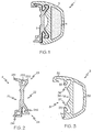
FIG. 1 is a cross-sectional view of the protective rub rail system of the present invention. -
FIG. 2 is a cross-sectional view of the rub rail track of the present invention. -
FIG. 3 is a cross-sectional view of the rub rail fender of the present invention. -
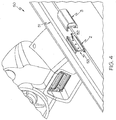
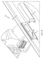
FIG. 4 is a break-away view of the rub rail system of the present invention, being fitted to the side of a vessel. -
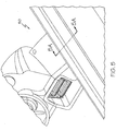
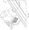
FIG. 5 is a perspective view of an exemplary vessel on which the present invention may be affixed. -
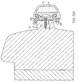
FIG. 5A is a cross-sectional view taken along line "5A" inFIG. 5 , showing the rub rail system of the present invention, as fitted to the side of a vessel.FIG. 1 is a cross-sectional view of the protective rub rail system of the present invention. -
FIG. 6 is a cross-sectional view of a second embodiment of the protective rub rail system of the present invention. -
FIG. 7 is a cross-sectional view of the second embodiment the rub rail track of the present invention. -
FIG. 8 is a cross-sectional view of the second embodiment the rub rail fender of the present invention. -
FIG. 9 is a break-away view of the second embodiment the rub rail system of the present invention, being fitted to the side of a vessel. -
FIG. 10 is a perspective view of an exemplary vessel on which the second embodiment of present invention may be affixed. -
FIG. 10A is a cross-sectional view taken along line "10A" inFIG. 10 , showing the second embodiment of rub rail system of the present invention, as fitted to the side of a vessel. - With reference to
FIG. 1 , shown is a cross-section of one embodiment of therub rail system 1 of the present invention comprising a rubrail track extrusion 2, a rubrail fender extrusion 3, andinner core 4. In some embodiments,track 2 andfender 3 are extruded members that can be extruded to any length desired, depending on the application.Track 2 is configured to be secured to the perimeter of a vessel whereinfender 3 is adapted to removeably and matingly engagetrack 2.Inner core 4 is disposed within a channel offender 3, as discussed in greater detail below. - In some embodiments,
track 2 is comprised of a rigid non-deformable material such as metal or hardened plastic. In some embodiments,fender 3 is comprised of a resilient, yet flexible material that resists abrasion and impact damage while also preventing damage or abrasion to another vessel or structure that the fender may contact or collide with. It is appreciated thatinner core 4 comprises an energy absorbing material that is substantially softer than the material offender 3, such thatfender 3 can transfer impact toinner core 4, which can better absorb impact. The materials used forfender 3 andcore 4 will be discussed in greater detail below. -
FIG. 2 is an isolated view of the cross-section of one embodiment oftrack 2 having avessel side 21 and afender side 22. Shown also isupper section 23 and alower section 24, each having a bifurcated or two-pronged configuration.Upper section 23 includes anupper lip 231 and anupper tang 232 which delimit an upper receivingcavity 233. In some embodiments,upper lip 231 extends rearward away fromvessel side 21 andupper tang 232 extends substantially upward.Lower section 24 includes alower lip 241, alower tang 242 which delimit alower receiving cavity 243. In some embodiments,lower lip 241 has a square cross-section such that, in its extruded form, thelower lip 241 is a square-tube, providing stability, strength, and rotational resistence for the bottom oftrack 2. Additionally, in some embodiments,lower tang 242 faces substantially downward. -
FIG. 3 is an isolated view of the cross-section of one embodiment offender 3. Thetrack side 31 offender 3 is configured to mate thefender side 22 oftrack 2.Fender 3 comprises anupper flange 32, anupper barb 33, alower flange 34, and alower barb 35. In some embodiments,upper flange 32 extends rearward, terminating with a hook-like or curved end.Lower flange 34 is substantially shorter thanupper flange 32, defining a short protrusion extending rearward fromlower barb 35. It is appreciated that, in some embodiments, theupper barb 33 extends substantially downward and thelower barb 35 extends substantially upward.Fender 3 also includes anupper recess 36 andlower recess 37, each delimited by theupper barb 33 andlower barb 35, respectively, which engagetrack 2 as described in detail below. Also shown iscurved recess 38 andchannel 39, which channel receives and is filled withinner core 4. -
FIGS. 1 ,4 , and5A depict the engagement oftrack 2 andfender 3.Fender 3 is designed such that it matingly engages with and is secured to track 2 without the need for external fasteners. Further,fender 3 is removeably engaged withtrack 2 to allow for easy repair and replacement of the fender. Theupper flange 32 offender 3 engages theupper lip 231 oftrack 2, with the hook-end offlange 32 fitting around the tip of theupper lip 231.Upper barb 33 engages and is received by upper receivingcavity 233 andupper tang 232 engages and is received byupper recess 36. Likewise,lower barb 35 engages and is received inlower receiving cavity 243 andlower tang 242 engages and is received bylower recess 37. In some embodiments,upper tang 232 andlower tang 242 oftrack 2 are designed to be slightly deformable so as to allowfender 3 to snap or slide into place. As shown, the smalllower flange 34 engages and rests against the bottom of squarelower lip 241. - Installation is accomplished with least resistance by first hooking
flange 32 toupper lip 231, snappingupper barb 33 into upper receivingcavity 233, then rotating thefender 3 downward aroundtrack 2 such thatlower barb 35 snaps intolower receiving cavity 243. This assures a tight and secure engagement that is easily repeatable across a number of segments of the rub rail. Alternatively,fender 3 may be installed by slidingupper barb 33 andlower barb 35 into upper receivingcavity 233 andlower receiving cavity 243, respectively at one end of thetrack 2 and providing it longitudinally intotrack 2 around the perimeter of the vessel. In this case, a lubricant applied betweentrack 2 andfender 3 may be used to ease installation. Further, the removable and repeatable engagement between thetrack 2 and thefender 3 allows for easier repair and replacement of the system. For instance, if damage to a segment offender 3 were to occur, but thetrack 2 was not damaged, the damagedfender 3 can easily be disengaged fromtrack 2 and replaced with a new one without the need to remove fasteners or any other structural components. - With reference to
FIGS. 4 ,5 , and5A ,track 2 is initially secured to the perimeter of thevessel 50. The specific mounting location oftrack 2 should not be considered limiting and it will depend on the structure characteristics of the vessel's design. However, in some embodiments,track 2 should be dimensioned such that the insides of theupper lip 231 andlower lip 241 fit snugly around the desired portion of the vessel to which the system is to be attached. For example, as shown inFIGS. 5 and5A , thevessel 50 has aprotrusion 51 extending outward from the vessel's hull, providing an ideal mounting location fortrack 2, withupper lip 231 snug against a top portion of the protrusion andlower lip 241 snug against a bottom portion. However, in some cases, a gap may exist between the bottom portion of the protrusion andlower lip 241, buttrack 2 will nevertheless remain secured. Referring back toFIG. 4 , a segment oftrack 2 is secured to the perimeter of thevessel 50 by one ormore fasteners 52 which may include screws, nails, rivets or other similar fastening means. In some embodiments,fasteners 52 are provided through the centerline oftrack 2. Further, in some embodiments, anadhesive sealant 53 may be applied between the vessel andtrack 2 providing a water lock and additional strength for the vessel/track joint. - With reference to
FIG. 6 , shown is a cross-section of another embodiment of the rub rail system of the present invention having a somewhat different configuration than that described above. As with the first embodiment, the system includes a rubrail track extrusion 7, a rubrail fender extrusion 8, and inner core 9 wherein the inner core 9 is comprised of a substantially softer material than that ofextrusion 8. -
FIG. 7 is an isolated view of the cross-section of one embodiment oftrack 7 having a vessel side 71 and a fender side 72. Shown also isupper section 73 and alower section 74, each having a bifurcated or two-pronged configuration.Upper section 73 includes anupper lip 731 and anupper tang 732 which delimit an upper receivingcavity 733. Theupper lip 731 may also include anotch 735 on the inside of thecavity 733. In some embodiments,upper lip 731 extends rearward away from vessel side 71 andupper tang 732 extends substantially upward.Lower section 74 includes alower lip 741, a lower tang 742 which delimit alower receiving cavity 743. In some embodiments,lower lip 741 has a square cross-section such that, in its extruded form, thelower lip 741. is a square-tube, providing stability, strength, and rotational resistance for the bottom oftrack 7. Additionally, in some embodiments, lower tang 742 faces substantially downward. -
FIG. 8 is an isolated view of the cross-section of one embodiment offender 8. Thetrack side 81 offender 8 is configured to mate the fender side 72 oftrack 7.Fender 8 comprises anupper barb 82, alower flange 83, and alower barb 84. In some embodiments,upper barb 82 includes anupper groove 85 which extends rearward therefrom.Lower flange 83 defines a short protrusion extending rearward fromlower barb 84. It is appreciated that, in some embodiments, theupper barb 82 extends substantially downward and thelower barb 84 extends substantially upward.Fender 8 also includes anupper recess 86 andlower recess 87, each delimited by theupper barb 82 andlower barb 84 respectively, which matingly engagetrack 7. Also shown iscurved recess 88 andchannel 89, which channel receives and is filled with inner core 9. In comparison to the embodiment shown inFIGS. 1-5A , this embodiment omits the upper flange of the fender and provides a track having a slightly truncatedupper lip 731 which prevents buckling of the fender in certain circumstances and certain installations, depending on the configuration of the vessel hull and perimeter. -
FIGS. 6 ,9 ,10 , and10A depict the engagement oftrack 7 andfender 8. As with the first exemplary embodiment,fender 8 is designed such that it matingly engages with and is secured to track 7 without the need for external fasteners. Further,fender 8 is removeably engaged withtrack 7 to allow for easy repair and replacement of the fender. Theupper barb 82 offender 8 engages and is received by upper receivingcavity 733 and upper tang 832 engages and is received byupper recess 86.Upper groove 85 engagesnotch 735 to provide additional stability and securement.Lower barb 84 engages and is received inlower receiving cavity 743 and lower tang 742 engages and is received bylower recess 87. In some embodiments,upper tang 732 and lower tang 742 oftrack 7 are designed to be slightly deformable so as to allowfender 8 to snap into place. As shown, the smalllower flange 83 engages and rests against the bottom of squarelower lip 741. Installation is accomplished with least resistance by snappingupper barb 82 into upper receivingcavity 733, then rotating thefender 8 downward aroundtrack 7 such thatlower barb 84 snaps intolower receiving cavity 743. This assures a tight and secure engagement that is easily repeatable across a number of segments of the rub rail. Alternatively,fender 8 may be installed by slidingupper barb 82 andlower barb 84 into upper receivingcavity 733 andlower receiving cavity 743, respectively at one end of thetrack 7 and providing it longitudinally intotrack 7 around the perimeter of the vessel. With reference toFIGS 9 ,10 , and 1A,track 7 is configured to engage the perimeter of avessel 50 substantially in accordance with the description above with respect totrack 2. - In operation, the rub rail system provides durable abrasion-resistant protection for the perimeter of a vessel. When a load is applied to fender 3 (or 8), the relatively hard, but flexible material will slightly deform, transforming the impact and shock to the relatively softer inner core 4 (or 9), allowing the inner core 4 (or 9) to absorb a substantial amount of the impact. In some embodiments, fender 3 (or 8) will deform or displace outwardly about curved recess 38 (or 88) as fender 3 (or 8) compresses against track 2 (or 7), which provides additional shock absorption while retaining a positive lock with track 2 (or 7). Fender 3 (or 8) is designed to be rigid enough to transfer shock to the soft core, but also resilient enough so as not to be damaged by impact, or cause damage by impact.
- As noted above, track 2 (or 7) is preferably comprised of a substantially rigid material such as hardened plastic or metal. In some embodiments, track 2 (or 7) is comprised of rigid polyvinyl chloride (PVC), selected for its relatively long life in outdoor conditions. However, other rigid plastics may be used such as acrylonitrile butadiene styrene (ABS), polycarbonate, Delrin (polyoxymethylene), Nylon, Hytrel and any other rigid plastic with a hardness of at least 50 durometer on the type-D scale. Further, in some embodiments, track 2 (or 7) is comprised of a metal such as stainless steel, aluminum, and various other metal alloys known in the art. Other suitable materials can be used provided they have the required rigidity and weather resistance.
- Fender 3 (or 8) and inner core 4 (or 9) are preferably comprised of a plastic material, it being appreciated that inner core 4 (or 9) is substantially softer than fender 3 (or 8). In some embodiments, fender 3 (or 8) and inner core 4 (or 9) are comprised of any of various known thermoplastic elastomers (TPE) with fender 3 (and 8) comprised of a harder and more rigid TPE than inner core 4 (or 9). TPE provides ideal weather resistance, long life, and stability over a wide temperature range. Other materials may be suitable, such as Flexible PVC, polyurethane, cell-foam materials or any other like material provided it has a hardness of between 5 and 98 durometer on the A-type scale. By way of example, in some embodiments, fender 3 (or 8) is comprised of a TPE having a Shore hardness between 75-90A durometer and inner core 4 (or 9) has a Shore hardness between 10-20A durometer. Further, in some embodiments, fender 3 (or 8) is comprised of a TPE having a Shore hardness of 85A durometer and inner core 4 (or 9) has a Shore hardness of 10A durometer. These ranges should be considered exemplary and non-limiting, however.
- It is appreciated that the components of rub rail system 1 (or 6), namely track 2 (or 7) and fender 3 (or 8) can be extruded to any length desired in order to effectively protect the perimeter of any vessel, regardless of the shape and contours thereof. Additionally, it is appreciated that while the specification and drawings herein describe use of the present invention in connection with marine vessels, the system is also useful for automobiles or other vehicles where perimeter protection is desired or needed.
- It is further appreciated that the rub rail system of the present invention has substantial advantages over the prior art. From a manufacturing standpoint, cast urethane fenders are much more labor intensive and require a more expensive base material. More sections are required to cover a given perimeter because the cast urethane fenders are not nearly as flexible as the instant invention. Likewise, soft hybrid collars are expensive to manufacture because they require (1) an outer skin that covers the entire collar, which is manufactured from several sections of a reinforced textile that must be cut and glued together; (2) a foam sub-core that must be hand-cut and custom fitted; (3) an inner air filled bladder that is comprised of a textile that also must be manually cut and glued. The present invention is also substantially easier to install in comparison to other systems that include a soft protective attribute. Cast urethane systems and RHIB's require gluing or integrated molding in order to provide protection, whereas the present invention can be installed like traditional rub rail system but include soft protection characteristics.
- The instant invention has been shown and described herein in what is considered to be the most practical and preferred embodiments. It is recognized, however, that departures may be made therefrom within the scope of the invention as claimed and that obvious modifications will occur to a person skilled in the art.
Claims (9)
- A rub rail system (1) for a vessel, comprising:a rigid track extrusion (2, 7), a resilient flexible fender extrusion (3, 8), and a shock absorbing inner core (4, 9);said inner core (4, 9) disposed in said fender extrusion (3, 8), wherein said inner core (4, 9) is substantially softer than said fender extrusion (3, 8);said track extrusion (2, 7) configured to attach to a perimeter of said vessel;said fender extrusion (3, 8) configured to matingly engage said track extrusion (2, 7);said rigid track extrusion (2, 7) including an upper (231, 731) and a lower lip (241, 741), said upper lip (231, 731) configured to engage a top portion of said perimeter of said vessel and said lower lip (241, 741) configured to engage a lower portion of said perimeter of said vessel;said fender extrusion (3, 8) including an upper flange (32) and a lower flange (34, 83), wherein said upper flange (32) engages said upper lip (231, 731) of said track extrusion (2, 7) and said lower flange (34, 83) engages said lower lip (241, 741) of said track extrusion (2, 7);characterised in that said upper flange (32) includes a hook-shaped end that engages a tip of said upper lip (231, 731) of said track extrusion (2, 7);and wherein said upper flange (32) is longer than said lower flange (34, 83).
- The rub rail system of claim 1, said fender extrusion (3, 8) including an upper barb (33, 82) and a lower barb (35, 84), said upper barb (33, 82) engaging an upper receiving cavity (233, 733) of said track extrusion (2, 7) and said lower barb (35, 84) engaging a lower receiving cavity (243, 743) of said track extrusion (2, 7).
- The rub rail system of claim 2, said track (2, 7) including having an upper tang (232, 732) and a lower tang (242, 742), said upper tang (232, 732) engaging an upper recess (36, 86) of said fender extrusion (3, 8) and said lower tang (242, 742) engaging a lower recess (37, 87) of said fender extrusion (3, 8).
- The rub rail system of claim 2, said fender extrusion (3, 8) including a lower flange (34, 83), wherein said lower flange engages said lower lip (241, 741) of said track extrusion (3, 8).
- The rub rail system of claim 2, said upper barb (33, 82) of said fender extrusion (3, 8) including a groove, wherein said groove engages a notch (735) in said upper receiving cavity (233, 733) of said track extrusion.
- The rub rail system of claim 1, wherein said rigid track extrusion (2, 7) is comprised of a plastic having a hardness of at least 50 durometer on the D-type scale
- The rub rail system of claim 6, wherein said plastic comprises polyvinyl chloride.
- The rub rail system of claim 1, wherein said fender extrusion (3, 8) and said inner core are comprised of thermoplastic elastomer having a hardness between 5 and 98 durometer on the A-type scale, said inner core having a lower hardness than said fender extrusion (3, 8).
- The rub rail system of claim 1, wherein one or more fasteners are provided through said track extrusion (2, 7) to attach said track extrusion (2, 7) to said perimeter of said vessel.
Applications Claiming Priority (2)
| Application Number | Priority Date | Filing Date | Title |
|---|---|---|---|
| US13/205,137 US8567333B2 (en) | 2011-08-08 | 2011-08-08 | Protective boat rub rail system |
| PCT/US2012/020415 WO2013022480A1 (en) | 2011-08-08 | 2012-01-06 | Protective boat rub rail system |
Publications (3)
| Publication Number | Publication Date |
|---|---|
| EP2741956A1 EP2741956A1 (en) | 2014-06-18 |
| EP2741956A4 EP2741956A4 (en) | 2015-07-22 |
| EP2741956B1 true EP2741956B1 (en) | 2017-04-26 |
Family
ID=47668765
Family Applications (1)
| Application Number | Title | Priority Date | Filing Date |
|---|---|---|---|
| EP12822158.7A Active EP2741956B1 (en) | 2011-08-08 | 2012-01-06 | Protective boat rub rail system |
Country Status (3)
| Country | Link |
|---|---|
| US (2) | US8567333B2 (en) |
| EP (1) | EP2741956B1 (en) |
| WO (1) | WO2013022480A1 (en) |
Families Citing this family (24)
| Publication number | Priority date | Publication date | Assignee | Title |
|---|---|---|---|---|
| US8480333B2 (en) | 2008-12-26 | 2013-07-09 | Steven Edward DeMay | Frame rail assemblies and interlocking frame rail systems |
| WO2012177711A1 (en) * | 2011-06-21 | 2012-12-27 | Sidoti Scott J | Edging systems |
| US8567333B2 (en) * | 2011-08-08 | 2013-10-29 | Boston Whaler, Inc. | Protective boat rub rail system |
| US9744710B2 (en) | 2012-01-13 | 2017-08-29 | U.S. Farathane Corporation | Assembly and process for creating an extruded pipe for use in a geothermal heat recovery operation |
| US10053828B2 (en) | 2012-01-13 | 2018-08-21 | U.S. Farathane Corporation | Assembly and process for creating an extruded marine dock bumper |
| NL2008800C2 (en) * | 2012-05-11 | 2013-11-12 | D B M Fabriek En Handelsonderneming B V | Fender, maritime structure, method for manufacturing. |
| CN102897123B (en) * | 2012-09-26 | 2014-10-22 | 桐乡市小老板特种塑料制品有限公司 | Device for buffering striking force |
| CN103015684A (en) * | 2012-12-26 | 2013-04-03 | 东莞承达木材制品有限公司 | A decorative line board and its installation method |
| NL2011968C2 (en) * | 2013-12-16 | 2015-06-17 | Linssen Holding B V | FENDERSYSTEM, VESSEL FITTED WITH SUCH FENDERSYSTEM AND FENDER SUITABLE FOR SUCH FENDERSYSTEM. |
| JP6668603B2 (en) * | 2015-03-30 | 2020-03-18 | 株式会社Ihi | Lifeboat |
| CN106005309A (en) * | 2016-06-22 | 2016-10-12 | 广州文冲船厂有限责任公司 | A kind of strand inhales outboard side rubber fender structure |
| USD802517S1 (en) * | 2016-09-13 | 2017-11-14 | Megaware Keelguard, Inc. | Pontoon guard |
| NL2018349B1 (en) | 2017-02-09 | 2018-09-04 | Fender Innovations Holding B V | Marine fender |
| US10543889B2 (en) * | 2017-06-08 | 2020-01-28 | Tessilmare S.R.L. | Fender for boats consisting of two components made of PVC coupled by a lock joint |
| GB2568861B (en) * | 2017-10-05 | 2020-08-05 | Profile Covers Ltd | Improved nautical fender |
| USD902318S1 (en) | 2018-05-21 | 2020-11-17 | Brunswick Corporation | Safety rail for a marine vessel |
| US11313093B2 (en) * | 2018-11-30 | 2022-04-26 | Steven Edward DeMay | Frame rail assemblies and interlocking frame rail systems |
| USD950772S1 (en) * | 2019-08-21 | 2022-05-03 | Taco Metals, Llc | Extruded vinyl rub rail |
| US11459045B1 (en) * | 2020-03-09 | 2022-10-04 | Doonan Specialized Trailer, LLC | Continuous contact rub rail |
| US12312798B2 (en) * | 2021-01-12 | 2025-05-27 | Boxabl Inc. | Foldable transportable buildings |
| US11702164B2 (en) | 2021-07-06 | 2023-07-18 | Hyundai Translead | Angular rub rails for trailers |
| US12606260B2 (en) | 2021-07-06 | 2026-04-21 | Hyundai Translead | Angular rub rails for trailers |
| US11814805B1 (en) * | 2021-12-15 | 2023-11-14 | Thomas R. Martin | Boat dock bumper and method of using the same |
| US12485982B1 (en) * | 2024-11-12 | 2025-12-02 | Dorsey Trailer LLC | Side rail for trailer |
Family Cites Families (19)
| Publication number | Priority date | Publication date | Assignee | Title |
|---|---|---|---|---|
| US2959146A (en) | 1958-12-03 | 1960-11-08 | Nat Lock Co | Bumper assembly for boats |
| US3109405A (en) | 1961-11-27 | 1963-11-05 | Nusinoff Willy | Boat bumper |
| US4083592A (en) * | 1977-01-06 | 1978-04-11 | Boston Metal Products Sales Corporation | Protective strip assembly |
| US4277526A (en) | 1978-01-16 | 1981-07-07 | The Standard Products Company | Protective and decorative molding having foam-filled channel |
| US4808451A (en) * | 1987-05-04 | 1989-02-28 | Boston Metal Products Corporation | Flush fitting protective strip assembly |
| US4946727A (en) * | 1989-03-08 | 1990-08-07 | Gerald Kessler | Dual durometer rub rail |
| US5013596A (en) * | 1989-07-21 | 1991-05-07 | Bostom Metal Products Corp. | Resilient strip and mounting member for flush fitting protective strip assembly |
| US5149569A (en) | 1990-02-12 | 1992-09-22 | Mccue Corporation | Base member for protective strip assembly |
| US5247897A (en) * | 1991-06-05 | 1993-09-28 | Pepp Dudley H | Jacketed cushioning device and method of manufacture |
| US5706751A (en) * | 1995-03-24 | 1998-01-13 | Hodges; Christopher A. | External rail system for a boat |
| US5743204A (en) * | 1996-08-29 | 1998-04-28 | Arctic Cat Inc. | Edge trim for watercraft |
| ATE280277T1 (en) * | 1997-08-08 | 2004-11-15 | Valpar Ind Ltd | FENDER |
| US20040200397A1 (en) | 2003-01-23 | 2004-10-14 | Morse Industries, Inc. | Rubstrip coextrusion for vessels |
| US6988457B2 (en) * | 2004-04-21 | 2006-01-24 | Cheng Fung Tsai | Structure for fastening shipboard-protecting fender |
| WO2007028116A2 (en) * | 2005-09-01 | 2007-03-08 | Barbour Plastics, Inc. | Rub rail with self-contained trim |
| ITMI20050390U1 (en) | 2005-11-08 | 2007-05-09 | Tessilmare S R L | FENDER FOR BOATS WITH INTERNAL CHANNEL |
| US7517001B1 (en) | 2007-02-20 | 2009-04-14 | Harold Goldbaum | Trim system for vehicle bumpers, doors and panels |
| US7918176B2 (en) * | 2008-09-30 | 2011-04-05 | Bombardier Recreational Products Inc. | Watercraft bumper |
| US8567333B2 (en) * | 2011-08-08 | 2013-10-29 | Boston Whaler, Inc. | Protective boat rub rail system |
-
2011
- 2011-08-08 US US13/205,137 patent/US8567333B2/en not_active Expired - Fee Related
-
2012
- 2012-01-06 WO PCT/US2012/020415 patent/WO2013022480A1/en not_active Ceased
- 2012-01-06 EP EP12822158.7A patent/EP2741956B1/en active Active
-
2013
- 2013-10-18 US US14/057,837 patent/US9073613B2/en active Active
Also Published As
| Publication number | Publication date |
|---|---|
| WO2013022480A1 (en) | 2013-02-14 |
| US20130036960A1 (en) | 2013-02-14 |
| US8567333B2 (en) | 2013-10-29 |
| US9073613B2 (en) | 2015-07-07 |
| EP2741956A1 (en) | 2014-06-18 |
| US20140048005A1 (en) | 2014-02-20 |
| EP2741956A4 (en) | 2015-07-22 |
Similar Documents
| Publication | Publication Date | Title |
|---|---|---|
| US9073613B2 (en) | Protective boat rub rail system | |
| US7624694B2 (en) | Resilient device | |
| US6364293B1 (en) | Fenders | |
| BR0111154B1 (en) | ASSEMBLY FOR SEALING FOR VEHICLE WINDOWS | |
| US8721224B2 (en) | Protective apparatus for marine structures | |
| CA3073408C (en) | Fender cap bracket, mud flap mounting bracket, and related methods of installation and use | |
| JP2011073486A (en) | Weather strip | |
| AU719460B2 (en) | Apparatus for reducing drag over a flow surface | |
| EP2521678B1 (en) | Shipping insert for protecting a motor vehicle window panel and attached molding during shipping and handling | |
| US6863009B1 (en) | Composite rub rail for watercraft, and method of installing same | |
| US5027736A (en) | Elastically deformable bumper system | |
| EP2978637B1 (en) | Roof rail system | |
| US20140338805A1 (en) | Noise-reducing device for a tire | |
| AU2021204291B2 (en) | A cover for a utility vehicle | |
| US20240051334A1 (en) | Insert, protection device, wheel and vehcile | |
| US7845304B2 (en) | Removable boat windshield | |
| HK1215698A1 (en) | Glazing system and methods | |
| US20060016378A1 (en) | Rub rail with a moisture seal | |
| RU161924U1 (en) | AUTOMATIC CAP OF AN INCREASED DIAMETER | |
| KR200208085Y1 (en) | Stuff for mitigation impact a bridge of assembly type | |
| CN217533015U (en) | Automobile wheel arch with scratch-resistant strip | |
| JP7629927B2 (en) | Sealing system for connecting a drainage device to a vehicle window pane | |
| US20040112272A1 (en) | Downcomer for marine vessels | |
| GB2317108A (en) | Sealed hinge bath screen | |
| JP4384563B2 (en) | Gaze guidance mark |
Legal Events
| Date | Code | Title | Description |
|---|---|---|---|
| PUAI | Public reference made under article 153(3) epc to a published international application that has entered the european phase |
Free format text: ORIGINAL CODE: 0009012 |
|
| 17P | Request for examination filed |
Effective date: 20140116 |
|
| AK | Designated contracting states |
Kind code of ref document: A1 Designated state(s): AL AT BE BG CH CY CZ DE DK EE ES FI FR GB GR HR HU IE IS IT LI LT LU LV MC MK MT NL NO PL PT RO RS SE SI SK SM TR |
|
| DAX | Request for extension of the european patent (deleted) | ||
| RA4 | Supplementary search report drawn up and despatched (corrected) |
Effective date: 20150624 |
|
| RIC1 | Information provided on ipc code assigned before grant |
Ipc: B63B 59/02 20060101AFI20150618BHEP |
|
| 17Q | First examination report despatched |
Effective date: 20160316 |
|
| GRAP | Despatch of communication of intention to grant a patent |
Free format text: ORIGINAL CODE: EPIDOSNIGR1 |
|
| STAA | Information on the status of an ep patent application or granted ep patent |
Free format text: STATUS: GRANT OF PATENT IS INTENDED |
|
| INTG | Intention to grant announced |
Effective date: 20161125 |
|
| GRAS | Grant fee paid |
Free format text: ORIGINAL CODE: EPIDOSNIGR3 |
|
| GRAA | (expected) grant |
Free format text: ORIGINAL CODE: 0009210 |
|
| STAA | Information on the status of an ep patent application or granted ep patent |
Free format text: STATUS: THE PATENT HAS BEEN GRANTED |
|
| AK | Designated contracting states |
Kind code of ref document: B1 Designated state(s): AL AT BE BG CH CY CZ DE DK EE ES FI FR GB GR HR HU IE IS IT LI LT LU LV MC MK MT NL NO PL PT RO RS SE SI SK SM TR |
|
| REG | Reference to a national code |
Ref country code: GB Ref legal event code: FG4D |
|
| REG | Reference to a national code |
Ref country code: CH Ref legal event code: EP |
|
| REG | Reference to a national code |
Ref country code: AT Ref legal event code: REF Ref document number: 887626 Country of ref document: AT Kind code of ref document: T Effective date: 20170515 |
|
| REG | Reference to a national code |
Ref country code: IE Ref legal event code: FG4D |
|
| REG | Reference to a national code |
Ref country code: DE Ref legal event code: R096 Ref document number: 602012031710 Country of ref document: DE |
|
| REG | Reference to a national code |
Ref country code: NL Ref legal event code: MP Effective date: 20170426 |
|
| REG | Reference to a national code |
Ref country code: LT Ref legal event code: MG4D |
|
| REG | Reference to a national code |
Ref country code: AT Ref legal event code: MK05 Ref document number: 887626 Country of ref document: AT Kind code of ref document: T Effective date: 20170426 |
|
| PG25 | Lapsed in a contracting state [announced via postgrant information from national office to epo] |
Ref country code: NL Free format text: LAPSE BECAUSE OF FAILURE TO SUBMIT A TRANSLATION OF THE DESCRIPTION OR TO PAY THE FEE WITHIN THE PRESCRIBED TIME-LIMIT Effective date: 20170426 |
|
| PG25 | Lapsed in a contracting state [announced via postgrant information from national office to epo] |
Ref country code: NO Free format text: LAPSE BECAUSE OF FAILURE TO SUBMIT A TRANSLATION OF THE DESCRIPTION OR TO PAY THE FEE WITHIN THE PRESCRIBED TIME-LIMIT Effective date: 20170726 Ref country code: FI Free format text: LAPSE BECAUSE OF FAILURE TO SUBMIT A TRANSLATION OF THE DESCRIPTION OR TO PAY THE FEE WITHIN THE PRESCRIBED TIME-LIMIT Effective date: 20170426 Ref country code: AT Free format text: LAPSE BECAUSE OF FAILURE TO SUBMIT A TRANSLATION OF THE DESCRIPTION OR TO PAY THE FEE WITHIN THE PRESCRIBED TIME-LIMIT Effective date: 20170426 Ref country code: HR Free format text: LAPSE BECAUSE OF FAILURE TO SUBMIT A TRANSLATION OF THE DESCRIPTION OR TO PAY THE FEE WITHIN THE PRESCRIBED TIME-LIMIT Effective date: 20170426 Ref country code: GR Free format text: LAPSE BECAUSE OF FAILURE TO SUBMIT A TRANSLATION OF THE DESCRIPTION OR TO PAY THE FEE WITHIN THE PRESCRIBED TIME-LIMIT Effective date: 20170727 Ref country code: ES Free format text: LAPSE BECAUSE OF FAILURE TO SUBMIT A TRANSLATION OF THE DESCRIPTION OR TO PAY THE FEE WITHIN THE PRESCRIBED TIME-LIMIT Effective date: 20170426 Ref country code: LT Free format text: LAPSE BECAUSE OF FAILURE TO SUBMIT A TRANSLATION OF THE DESCRIPTION OR TO PAY THE FEE WITHIN THE PRESCRIBED TIME-LIMIT Effective date: 20170426 |
|
| PG25 | Lapsed in a contracting state [announced via postgrant information from national office to epo] |
Ref country code: PL Free format text: LAPSE BECAUSE OF FAILURE TO SUBMIT A TRANSLATION OF THE DESCRIPTION OR TO PAY THE FEE WITHIN THE PRESCRIBED TIME-LIMIT Effective date: 20170426 Ref country code: SE Free format text: LAPSE BECAUSE OF FAILURE TO SUBMIT A TRANSLATION OF THE DESCRIPTION OR TO PAY THE FEE WITHIN THE PRESCRIBED TIME-LIMIT Effective date: 20170426 Ref country code: RS Free format text: LAPSE BECAUSE OF FAILURE TO SUBMIT A TRANSLATION OF THE DESCRIPTION OR TO PAY THE FEE WITHIN THE PRESCRIBED TIME-LIMIT Effective date: 20170426 Ref country code: IS Free format text: LAPSE BECAUSE OF FAILURE TO SUBMIT A TRANSLATION OF THE DESCRIPTION OR TO PAY THE FEE WITHIN THE PRESCRIBED TIME-LIMIT Effective date: 20170826 Ref country code: BG Free format text: LAPSE BECAUSE OF FAILURE TO SUBMIT A TRANSLATION OF THE DESCRIPTION OR TO PAY THE FEE WITHIN THE PRESCRIBED TIME-LIMIT Effective date: 20170726 Ref country code: LV Free format text: LAPSE BECAUSE OF FAILURE TO SUBMIT A TRANSLATION OF THE DESCRIPTION OR TO PAY THE FEE WITHIN THE PRESCRIBED TIME-LIMIT Effective date: 20170426 |
|
| REG | Reference to a national code |
Ref country code: FR Ref legal event code: PLFP Year of fee payment: 7 |
|
| REG | Reference to a national code |
Ref country code: DE Ref legal event code: R097 Ref document number: 602012031710 Country of ref document: DE |
|
| PG25 | Lapsed in a contracting state [announced via postgrant information from national office to epo] |
Ref country code: DK Free format text: LAPSE BECAUSE OF FAILURE TO SUBMIT A TRANSLATION OF THE DESCRIPTION OR TO PAY THE FEE WITHIN THE PRESCRIBED TIME-LIMIT Effective date: 20170426 Ref country code: RO Free format text: LAPSE BECAUSE OF FAILURE TO SUBMIT A TRANSLATION OF THE DESCRIPTION OR TO PAY THE FEE WITHIN THE PRESCRIBED TIME-LIMIT Effective date: 20170426 Ref country code: CZ Free format text: LAPSE BECAUSE OF FAILURE TO SUBMIT A TRANSLATION OF THE DESCRIPTION OR TO PAY THE FEE WITHIN THE PRESCRIBED TIME-LIMIT Effective date: 20170426 Ref country code: SK Free format text: LAPSE BECAUSE OF FAILURE TO SUBMIT A TRANSLATION OF THE DESCRIPTION OR TO PAY THE FEE WITHIN THE PRESCRIBED TIME-LIMIT Effective date: 20170426 Ref country code: EE Free format text: LAPSE BECAUSE OF FAILURE TO SUBMIT A TRANSLATION OF THE DESCRIPTION OR TO PAY THE FEE WITHIN THE PRESCRIBED TIME-LIMIT Effective date: 20170426 |
|
| PG25 | Lapsed in a contracting state [announced via postgrant information from national office to epo] |
Ref country code: SM Free format text: LAPSE BECAUSE OF FAILURE TO SUBMIT A TRANSLATION OF THE DESCRIPTION OR TO PAY THE FEE WITHIN THE PRESCRIBED TIME-LIMIT Effective date: 20170426 |
|
| PLBE | No opposition filed within time limit |
Free format text: ORIGINAL CODE: 0009261 |
|
| STAA | Information on the status of an ep patent application or granted ep patent |
Free format text: STATUS: NO OPPOSITION FILED WITHIN TIME LIMIT |
|
| 26N | No opposition filed |
Effective date: 20180129 |
|
| PG25 | Lapsed in a contracting state [announced via postgrant information from national office to epo] |
Ref country code: SI Free format text: LAPSE BECAUSE OF FAILURE TO SUBMIT A TRANSLATION OF THE DESCRIPTION OR TO PAY THE FEE WITHIN THE PRESCRIBED TIME-LIMIT Effective date: 20170426 |
|
| REG | Reference to a national code |
Ref country code: CH Ref legal event code: PL |
|
| PG25 | Lapsed in a contracting state [announced via postgrant information from national office to epo] |
Ref country code: LU Free format text: LAPSE BECAUSE OF NON-PAYMENT OF DUE FEES Effective date: 20180106 |
|
| REG | Reference to a national code |
Ref country code: IE Ref legal event code: MM4A |
|
| REG | Reference to a national code |
Ref country code: BE Ref legal event code: MM Effective date: 20180131 |
|
| PG25 | Lapsed in a contracting state [announced via postgrant information from national office to epo] |
Ref country code: BE Free format text: LAPSE BECAUSE OF NON-PAYMENT OF DUE FEES Effective date: 20180131 Ref country code: LI Free format text: LAPSE BECAUSE OF NON-PAYMENT OF DUE FEES Effective date: 20180131 Ref country code: CH Free format text: LAPSE BECAUSE OF NON-PAYMENT OF DUE FEES Effective date: 20180131 |
|
| PG25 | Lapsed in a contracting state [announced via postgrant information from national office to epo] |
Ref country code: IE Free format text: LAPSE BECAUSE OF NON-PAYMENT OF DUE FEES Effective date: 20180106 |
|
| PG25 | Lapsed in a contracting state [announced via postgrant information from national office to epo] |
Ref country code: MC Free format text: LAPSE BECAUSE OF FAILURE TO SUBMIT A TRANSLATION OF THE DESCRIPTION OR TO PAY THE FEE WITHIN THE PRESCRIBED TIME-LIMIT Effective date: 20170426 |
|
| PG25 | Lapsed in a contracting state [announced via postgrant information from national office to epo] |
Ref country code: MT Free format text: LAPSE BECAUSE OF NON-PAYMENT OF DUE FEES Effective date: 20180106 |
|
| PG25 | Lapsed in a contracting state [announced via postgrant information from national office to epo] |
Ref country code: TR Free format text: LAPSE BECAUSE OF FAILURE TO SUBMIT A TRANSLATION OF THE DESCRIPTION OR TO PAY THE FEE WITHIN THE PRESCRIBED TIME-LIMIT Effective date: 20170426 |
|
| PG25 | Lapsed in a contracting state [announced via postgrant information from national office to epo] |
Ref country code: PT Free format text: LAPSE BECAUSE OF FAILURE TO SUBMIT A TRANSLATION OF THE DESCRIPTION OR TO PAY THE FEE WITHIN THE PRESCRIBED TIME-LIMIT Effective date: 20170426 Ref country code: HU Free format text: LAPSE BECAUSE OF FAILURE TO SUBMIT A TRANSLATION OF THE DESCRIPTION OR TO PAY THE FEE WITHIN THE PRESCRIBED TIME-LIMIT; INVALID AB INITIO Effective date: 20120106 |
|
| PG25 | Lapsed in a contracting state [announced via postgrant information from national office to epo] |
Ref country code: CY Free format text: LAPSE BECAUSE OF FAILURE TO SUBMIT A TRANSLATION OF THE DESCRIPTION OR TO PAY THE FEE WITHIN THE PRESCRIBED TIME-LIMIT Effective date: 20170426 Ref country code: MK Free format text: LAPSE BECAUSE OF NON-PAYMENT OF DUE FEES Effective date: 20170426 |
|
| PG25 | Lapsed in a contracting state [announced via postgrant information from national office to epo] |
Ref country code: AL Free format text: LAPSE BECAUSE OF FAILURE TO SUBMIT A TRANSLATION OF THE DESCRIPTION OR TO PAY THE FEE WITHIN THE PRESCRIBED TIME-LIMIT Effective date: 20170426 |
|
| P01 | Opt-out of the competence of the unified patent court (upc) registered |
Effective date: 20230330 |
|
| PGFP | Annual fee paid to national office [announced via postgrant information from national office to epo] |
Ref country code: GB Payment date: 20260127 Year of fee payment: 15 |
|
| PGFP | Annual fee paid to national office [announced via postgrant information from national office to epo] |
Ref country code: DE Payment date: 20251211 Year of fee payment: 15 |
|
| PGFP | Annual fee paid to national office [announced via postgrant information from national office to epo] |
Ref country code: IT Payment date: 20251211 Year of fee payment: 15 |
|
| PGFP | Annual fee paid to national office [announced via postgrant information from national office to epo] |
Ref country code: FR Payment date: 20260121 Year of fee payment: 15 |