EP2741952B1 - Front structure for vehicle - Google Patents
Front structure for vehicle Download PDFInfo
- Publication number
- EP2741952B1 EP2741952B1 EP20120746118 EP12746118A EP2741952B1 EP 2741952 B1 EP2741952 B1 EP 2741952B1 EP 20120746118 EP20120746118 EP 20120746118 EP 12746118 A EP12746118 A EP 12746118A EP 2741952 B1 EP2741952 B1 EP 2741952B1
- Authority
- EP
- European Patent Office
- Prior art keywords
- dash panel
- vehicle
- panel
- joined
- cowl
- Prior art date
- Legal status (The legal status is an assumption and is not a legal conclusion. Google has not performed a legal analysis and makes no representation as to the accuracy of the status listed.)
- Not-in-force
Links
Images


Classifications
-
- B—PERFORMING OPERATIONS; TRANSPORTING
- B62—LAND VEHICLES FOR TRAVELLING OTHERWISE THAN ON RAILS
- B62D—MOTOR VEHICLES; TRAILERS
- B62D25/00—Superstructure or monocoque structure sub-units; Parts or details thereof not otherwise provided for
- B62D25/08—Front or rear portions
- B62D25/14—Dashboards as superstructure sub-units
- B62D25/145—Dashboards as superstructure sub-units having a crossbeam incorporated therein
-
- B—PERFORMING OPERATIONS; TRANSPORTING
- B62—LAND VEHICLES FOR TRAVELLING OTHERWISE THAN ON RAILS
- B62D—MOTOR VEHICLES; TRAILERS
- B62D25/00—Superstructure or monocoque structure sub-units; Parts or details thereof not otherwise provided for
- B62D25/08—Front or rear portions
- B62D25/14—Dashboards as superstructure sub-units
-
- B—PERFORMING OPERATIONS; TRANSPORTING
- B62—LAND VEHICLES FOR TRAVELLING OTHERWISE THAN ON RAILS
- B62D—MOTOR VEHICLES; TRAILERS
- B62D21/00—Understructures, i.e. chassis frame on which a vehicle body may be mounted
- B62D21/09—Means for mounting load bearing surfaces
-
- B—PERFORMING OPERATIONS; TRANSPORTING
- B62—LAND VEHICLES FOR TRAVELLING OTHERWISE THAN ON RAILS
- B62D—MOTOR VEHICLES; TRAILERS
- B62D25/00—Superstructure or monocoque structure sub-units; Parts or details thereof not otherwise provided for
- B62D25/08—Front or rear portions
- B62D25/081—Cowls
Definitions
- the present invention relates to a front structure for a vehicle in which a dash panel and a cowl are joined together.
- a configuration is known in which a first reinforcement that is arranged along the entire length of a cowl rear wall and a dash panel which is joined to the cowl front wall are coupled by a second reinforcement at the center in a vehicle width direction (refer to Japanese Utility Model Application Publication No. 5-46668 ( JP 5-46668 U ), for example).
- a structure which includes a brace that has one end which is joined to a cowl rear wall and the other end which is joined to a pair of patches which are secured to a dash panel at both sides, in a vehicle width direction, of an opening of the dash panel which is joined to a cowl front wall is known (refer to Japanese Patent Application Publication No. 2009-113568 ( JP 2009-113568 A ), for example).
- a front structure for an automobile body which includes a brace that couples the back side of a dash panel which is joined to a cowl bottom wall in a vertically overlapping relationship and a cowl rear wall at the center in a vehicle width direction (refer to Japanese Patent Application Publication No. 2004-130976 ( JP 2004-130976 A ), for example).
- the present invention provides a front structure for a vehicle which can improve the strength against separation of the junction where a dash panel and a cowl are joined in an overlapping relationship in a vehicle length direction.
- the solution envisaged for the above problem is represented by the matter of independent claim 1.
- the preamble features of said claim being taken from the disclosure of document EP-A-0 426 107 .
- a front structure for vehicle which includes: a cowl panel which has at least a front wall and a bottom wall that extends from a lower end of the front wall toward a rear of the vehicle and which opens toward a top of the vehicle; a dash panel which has an upper end portion which is joined to the front wall of the cowl panel in an overlapping relationship in a vehicle length direction; and a reinforcing member which has a lower end side which is joined to the dash panel at a junction and an upper end side which is joined to the bottom wall of the cowl panel to form a closed cross-section in conjunction with the dash panel and the bottom wall.
- the reinforcing member connects the dash panel and the bottom wall of the cowl panel across the junction where the front wall of the cowl panel and upper end side of the dash panel are joined in an overlapping relationship in a vehicle length direction.
- the dash panel, the bottom wall and the reinforcing member form a closed cross-section as seen in a side view.
- the front structure for a vehicle as described above can improve the strength against separation of the junction where the dash panel and the cowl panel are overlapped in a vehicle length direction.
- the reinforcing member is provided at a location in a vehicle width direction where the strength against separation would be relatively low without the reinforcing member, the strength against separation of the junction between the dash panel and the cowl panel can be efficiently improved compared to the case where a reinforcing member which extends, in a wide range in a vehicle width direction is provided.
- the dash panel may have a pair of folded portions that are formed apart from each other in a vehicle width direction, and the junction between the lower end side of the reinforcing member and the dash panel may include a plurality of main junctions that are located between the pair of folded portions of the dash panel.
- the folded portions of the dash panel serve as high-rigidity portions and tend to transmit a force from a wheel to the junction with the cowl panel.
- a portion of the dash panel above the region between the pair of folded portions would have a relatively low strength against separation (tend to undergo stress concentration) without the reinforcing member.
- the reinforcing member which is disposed locally in a vehicle width direction, can improve the strength against separation of the junction between the dash panel and the cowl panel.
- the reinforcing member has a plurality of main junctions, the stress that is generated at the junction between the reinforcing member and the dash panel is reduced compared to a configuration with only one main junction.
- the junction between the lower end side of the reinforcing member and the dash panel may include at least two subsidiary junctions, the pair of folded portions of the dash panel being sandwiched between the subsidiary junctions in a vehicle width direction.
- the subsidiary junctions help to prevent misalignment of the reinforcing member relative to the dash panel before joining of the main junctions.
- the main junctions can be properly joined at desired locations relative to the dash panel. This enables the main junctions to contribute to the improvement of the strength against separation of the junction between the dash panel and the cowl panel.
- the subsidiary junctions may be formed on a pair of leg portions that extend from a lower end side of the reinforcing member in opposite directions along a vehicle width direction.
- the subsidiary junctions are formed on leg portions which extend from a lower portion of the reinforcing member, the subsidiary junctions can be located on both sides of a surface between the pair of folded portions without increasing the size of the reinforcing member.
- the upper end side of the reinforcing member may be joined to the bottom wall of the cowl panel at a plurality of points.
- the reinforcing member is joined to the bottom wall of the cowl panel at a plurality of points, the stress that is generated at the junction between the reinforcing member and the cowl panel can be reduced compared to a configuration in which the bottom wall of the cowl panel is joined at only one point.
- the reinforcing member may have a main body portion which forms a closed cross-section in conjunction with the dash panel and the bottom wall of the cowl panel and which has a first edge that linearly extends along a first end side thereof in a vehicle width direction between the dash panel and the bottom wall and a second edge that extends in an arcuate configuration as seen in a side view along a second end side thereof in a vehicle width direction between the dash panel and the bottom wall; and a reinforcing wall which protrudes in a vehicle length direction from the second edge.
- the reinforcing member has a first edge that extends between the dash panel and the bottom wall of the cowl panel linearly and a second edge that extends between the dash panel and the bottom wall of the cowl panel in an arcuate configuration (to be convex either forward or rearward) as seen in a side view.
- the distance from the reinforcing member to the dash panel and the cowl panel is greater or smaller on the second edge side than on the first edge side. The reinforcing member can therefore be prevented from interfering with other components.
- the second edge which has an arcuate configuration, may be disadvantageous in terms of strength against tension, but is reinforced against tension by the reinforcing wall, which protrudes from the second edge in a vehicle length direction.
- the second edge can help the reinforcing member to exhibit a desired reinforcing effect.
- the reinforcing member may include a main body portion which forms a closed cross-section in conjunction with the dash panel and the bottom wall of the cowl panel; a lower flange which is bent at a lower end of the main body portion and which extends along a back side of the dash panel and is joined to the dash panel; an upper flange that is bent at an upper end of the main body portion and which extends along a lower face of the bottom wall and is joined to the bottom wall; a lower restricting portion that restricts deformation which tends to increase a bend angle between the main body portion and the lower flange; and an upper restricting portion that restricts deformation which tends to increase a bend angle between the main body portion and the upper flange.
- a bend is formed between the main body portion and the upper flange and between the main body portion and the lower flange of the reinforcing member, and the reinforcing member undergoes deformation which tends to increase the bend angles of the bends (to unfold the bends) when a tensile load is applied to the reinforcing member.
- the reinforcing member has an upper restricting portion between the main body portion and the upper flange and a lower restricting portion between the main body portion and the lower flange.
- the main body portion of the reinforcing member which forms a closed cross-section in conjunction with the dash panel and the cowl panel, may have a plurality of openings.
- the main body portion of the reinforcing member has a plurality of openings that can be used to maintain the reinforcing member in a desired position.
- the reinforcing member can be joined to the dash panel and the cowl panel in an appropriate position relative to the dash panel and the cowl panel.
- the main junctions can be properly joined in a desired position relative to the dash panel. This enables the main junctions to contribute to the improvement of the strength against separation of the junction between the dash panel and the cowl panel.
- the front structure for a vehicle of the present invention is highly effective in improving the strength against separation of the junction where the dash panel and the cowl panel are overlapped in a vehicle length direction.
- a vehicle body front structure 10 as a front structure for a vehicle according to a first embodiment of the present invention with reference to FIG 1 to FIGs. 6A and 6B .
- the arrow FR, the arrow UP, the arrow RH and the arrow LH which are shown as needed in the drawings, indicates the forward (traveling) direction along the vehicle length direction, the upward direction along the vehicle height direction, the right side with respect to the traveling direction (one side with respect to a vehicle width direction), and the left side with respect to the traveling direction (the other side with respect to a vehicle width direction), respectively.
- front and rear refer to the front and rear sides in the vehicle length direction, the upper and lower sides in the vehicle height direction, and the right and left sides with respect to the traveling direction of the vehicle, respectively, unless otherwise noted.
- FIG 3 is a perspective view that illustrates a part of the right side of a vehicle body B of an automobile V to which the vehicle body front structure 10 is applied. Because the vehicle body B is basically formed in a generally bilaterally symmetric fashion except the parts that are described later, the right side (the passenger side in this embodiment) of the vehicle body B is primarily described in the following description. As shown in FIG 3 , the vehicle body B includes a front pillar 12, an apron upper member 14 that extends forward from a vertical intermediate portion of the front pillar 12, and an apron panel 16 that extends downward from the apron upper member 14. A front suspension tower 18 to which an upper end of a front suspension (not shown) is coupled is integrally formed with the apron panel 16, which constitutes the vehicle body B.
- the vehicle body B also includes a front side member 20 as a skeletal member which extends in a vehicle length direction.
- One end side of a bumper reinforcement in a vehicle width direction is coupled to a front end (not shown) of the front side member 20.
- the front side member 20 includes a front portion 20F that extends in a vehicle length direction in an engine room E, a kick portion 20K which is curved along a dash panel 22, which is described later, and a rear portion 20R which forms a skeleton that is elongated in a vehicle length direction in conjunction with a floor panel (not shown) behind the kick portion 20K.
- the front portion 20F of the front side member 20 has a rear portion which is joined to an inner portion of the front suspension tower 18 in a vehicle width direction.
- the vehicle body B also includes a dash panel 22 which separates the engine room E and a cabin C.
- the dash panel 22 has a lower end side which is joined to a front end of a floor panel (not shown) along the almost entire length thereof in a vehicle width direction.
- a dash cross member 24 which forms a skeletal structure with a closed cross-section in conjunction with the dash panel 22 is joined to a front side of the dash panel 22 along the almost entire length thereof in a vehicle width direction.
- the front portion 20F of the front side member 20 has a rear end which is joined in an abutting relationship with the dash cross member 24.
- the kick portion 20K of the front side member 20 is joined to a front face of the dash panel 22 and continues to the rear portion 20R, which is joined to a lower face of the floor panel.
- the dash panel 22 has an upper end side to which a cowl panel 28 that constitutes a cowl member 26 is joined.
- the cowl panel 28, which is a member that has an inverted hat-like cross-section that opens upward and is elongated in a vehicle width direction, extends between vertical intermediate portions of right and left front pillars 12.
- the cowl panel 28 has longitudinal ends which are joined to a corresponding one of right and left apron upper members 14.
- the cowl member 26 including the cowl panel 28 is configured to support a windshield glass in conjunction with the right and left front pillars 12 and a roof head member (not shown).
- the load from a front wheel is transmitted to the junction between the dash panel 22 and the cowl panel 28 as a load which tends to cause separation thereof via the front suspension tower 18 and the front pillar 12.
- the transmission of load is described later in connection with the effects of this embodiment.
- vehicle body front structure 10 The essential features of the vehicle body front structure 10 are described in detail below.
- the cowl panel 28 includes, as essential components, a front wall 28F and a rear wall 28R which are opposed to each other in a vehicle length direction, and a bottom wall 28B which connects lower ends of the front wall 28F and the rear wall 28R.
- the cowl panel 28 opens upward as described above.
- a cowl vibration-damping steel plate 30 with a generally L-shaped configuration as seen in a side view is joined to a lower portion of the front wall 28F and a front portion of the bottom wall 28B by, for example, spot welding.
- the cowl vibration-damping steel plate 30 includes, as essential components, a front wall portion 30F which is joined to the front wall 28F, and a lower wall portion 30L which is joined to the bottom wall 28B.
- the dash panel 22 has an upper end portion 22U which is joined to the front wall 28F of the cowl panel 28 in an overlapping relationship in a vehicle length direction.
- the upper end portion 22U of the dash panel 22 and a lower portion of the front wall 28F of the cowl panel 28 are joined to each other along the almost entire length thereof in a vehicle width direction via the front wall portion 30F of the cowl vibration-damping steel plate 30 at a junction Jcd.
- the junction Jcd in this embodiment is formed by integrally joining the front wall portion 30F, the front wall 28F, and the upper end portion 22U, which are overlapped in a vehicle length direction, by spot welding.
- the dash panel 22 which is joined to the cowl panel 28 at the upper end portion 22U as described above, is bilaterally asymmetric because of the difference in shape of the cabin C and the engine room E between the driver side and passenger side.
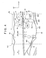
- the dash panel 22 has a stepped portion 22S in a region A between the center line CL in a vehicle width direction as seen in a front view and a spot 18C where the right front suspension tower 18 is coupled to a front suspension (phantom line IL1).
- the stepped portion 22S is offset with respect to the center of the vehicle body B in a vehicle width direction.
- the stepped portion 22S serves as an inclined vertical wall which connects a general portion 22G of the dash panel 22 and a bearing surface portion 22Z that protrudes forward farther than the general portion 22G
- a first ridge line RL1 which serves as a boundary with the bearing surface portion 22Z is formed on the right side of the stepped portion 22S
- a second ridge line RL2 which serves as a boundary with the general portion 22G is formed on the left side of the stepped portion 22S.
- the dash panel 22 is formed by press working, and the first ridge line RL1 and the second ridge line RL2 are one example of a pair of folded portions.
- the bearing surface portion 22Z of the dash panel 22 has a through hole 22H that extends through the dash panel 22 at a location close to the stepped portion 22S.
- the dash panel 22 in this embodiment is covered with a second dash panel 32 from the back side.
- the second dash panel 32 is joined to the dash panel 22 to reinforce the dash panel 22.
- the second dash panel 32 is configured to cover the dash panel 22 generally entirely from the back side except an upper part of the stepped portion 22S and a portion around the through hole 22H of the bearing surface portion 22Z.
- the vehicle body front structure 10 (the vehicle body B) has a patch 34 as a reinforcing member that couples the dash panel 22 and the cowl panel 28 at a fixed location in the region A as seen in a front view.
- the patch 34 extends between the stepped portion 22S of the dash panel 22 and the bottom wall 28B of the cowl panel 28 as shown in FIG. 1 and FIG 4 .
- the patch 34 has a lower flange 34L that forms a lower part thereof and is joined to the stepped portion 22S of the dash panel 22, and an upper flange 34U that forms an upper part thereof and is joined to a front portion of the bottom wall 28B of the cowl panel 28.
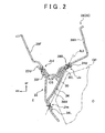
- a patch main body 34M of the patch 34 as a main body portion between the lower flange 34L and the upper flange 34U forms a closed cross-sectional portion CS which has a generally triangular shape as seen in a side view in conjunction with the dash panel 22 and the bottom wall 28B of the cowl panel 28 as shown in FIG. 2 .
- the patch main body 34M is separated from the dash panel 22 and the cowl panel 28.
- the patch 34 and its joint (coupling) structure are described in more detail below.
- the patch main body 34M which has a plate-like configuration, has a liner left edge 34EL which is slightly inclined with respect to a vehicle height direction, and an arcuate right edge 34ER which is curved to be convex rearward as seen in a side view.
- a reinforcing flange 34F as a reinforcing wall extends rearward from the curved right edge 34ER of the patch main body 34M.
- the right edge 34ER of the patch main body 34M is reinforced in a vehicle height (tensile) direction by the reinforcing flange 34F.
- the patch main body 34M has an attachment datum hole 34Hs into which a datum pin of a welding apparatus is inserted when the patch 34 is joined to the vehicle body B, and a pair of jig attachment holes 34Hj as a plurality of openings that are used to maintain the attachment position of the patch 34 relative to the vehicle body B.
- the upper flange 34U is formed by bending an upper end of the patch main body 34M rearward, and is joined to the bottom wall 28B at two upper junctions Ju that are arranged at right and left ends thereof as shown in FIG. 1 .
- the patch 34 has a rib 34R, at the center in its width direction, as an upper restricting portion which is formed across the boundary between the upper flange 34U and an upper end portion of the patch main body 34M and protrudes rearward.
- the patch 34 is reinforced against deformation which tends to increase the bend angle (tends to eliminate (unfold) the bend) between the patch main body 34M and the upper flange 34U compared to a configuration without the rib 34R.
- the reinforcing flange 34F is connected to the right edge 34ER of the upper flange 34U.
- the lower flange 34L is formed by bending a lower end of the patch main body 34M rearward, and joined to the stepped portion 22S at two, upper and lower, lower main junctions Jlm as a plurality of main junctions that are shown in FIG. 1 .
- the lower main junctions Jlm are configured to ensure the joint strength between a lower portion of the patch 34 and the dash panel 22.
- a pair of extended leg portions 34P1 and 34P2 as leg portions extend laterally in opposite directions from a lower portion of the patch main body 34M of the patch 34, that is, the lower flange 34L.
- the extended leg portion 34P1 which extends rightward, extends farther rightward than a lower portion of the reinforcing flange 34F and is joined to a back side of the bearing surface portion 22Z of the dash panel 22 at a lower subsidiary junction Jls as a subsidiary junction that is located near its extended end.
- the extended leg portion 34P2 which extends farther leftward from a lower portion of the patch main body 34M and a left end of the lower flange 34L, is joined to a back side of the general portion 22G of the dash panel 22 at a lower subsidiary junction Jls as a subsidiary junction that is located near its extended end.
- the extended leg portion 34P2 is joined to the dash panel 22 via the second dash panel 32 at the lower subsidiary junction Jls.
- the right and left lower subsidiary junctions Jls are joined at locations on both sides of the stepped portion 22S (the patch main body 34M) of the dash panel 22 in a vehicle width direction before the lower main junctions Jlm are joined so that the deviation of the coupling location of a lower portion of the patch 34 can be within an acceptable range relative to the dash panel 22.
- the extended leg portion 34P2 forms a ridge line (folded portion) RL3 which is convex upward along the boundary with the lower flange 34L, and forms a ridge line (folded portion) RL4 which is convex rearward along the boundary with a lower portion of the patch main body 34M.
- the patch 34 is reinforced against deformation which tends to increase the bend angle (to eliminate (unfold) the bend) between the patch main body 34M and the lower flange 34L (and the extended leg portion 34P2) compared to a configuration without the ridge lines RL3 and RL4.
- the ridge line RL3 along the boundary between the extended leg portion 34P2 and the lower flange 34L and the ridge line RL4 along the boundary between the extended leg portion 34P2 and a lower portion of the patch main body 34M as described above are one example of lower restricting portions.
- junctions where the patch 34 is joined to the dash panel 22 and the cowl panel 28 as described above are formed by spot welding.
- the joint may be made by means of bolts and nuts instead of welding.
- components CP such as a dash inner silencer (insulator), an air-conditioning unit (HVAC) and a wire harness, are disposed in a cabin C side space including the location where the patch 34 is joined to the dash panel 22 as shown in FIG. 2 .
- the patch main body 34M of the patch 34 has a curved right edge as described above in order to avoid interference with the components CP (including the range of movement of movable components, such as the wire harness).
- the dash panel 22 is assembled to the vehicle body B before the cowl member 26 is assembled to the vehicle body B when the vehicle body B is assembled, and, in this state, the patch 34 is secured to the dash panel 22 at the two lower subsidiary junctions Jls.
- the patch 34 is secured to the stepped portion 22S of the dash panel 22 at the two lower main junctions Jlm.
- the patch 34 is secured to the bottom wall 28B of the cowl panel 28 through the cowl vibration-damping steel plate 30 at the upper junctions Ju in the final assembly step.
- the patch 34 is attached to a jig at the two jig attachment holes 34Hj of the patch main body 34M and held in proper position relative to the dash panel 22.
- the patch 34 is attached to a jig on a hand of an assembling robot at the jig attachment holes 34Hj and transported by the robot to (inserted into) a desired location in the vehicle body B during assembly.
- a welding datum pin is inserted into the attachment datum hole 34Hs, and, in this state, the patch 34 is secured in place at the lower subsidiary junctions Jls as described above.
- junction Jcd where the upper end portion 22U of the dash panel 22 and the front wall 28F of the cowl panel 28 are joined in an overlapping relationship in a vehicle length direction by spot welding undergoes deformation (stress) which tends to cause separation thereof.
- deformation in a vehicle length direction
- the deformation in a vehicle length direction
- separation of the junction Jcd tends to be large when the right and left front wheels are moved in vertically opposite phases.
- a load (deformation) toward the front of the vehicle which is caused by the moment M is transmitted to the junction Jcd along a phantom straight line that connects the front side member 20 and the stepped portion 22S.
- the load which is caused by the moment M is less likely to be absorbed (attenuated) by deformation of the panel on the routes along the two ridge lines RL1 and RL2 (the stepped portion 22S) than on a route through any other portion, a larger load is transmitted to the junction Jcd along the ridge lines RL1 and RL2 than along any other portion.
- the deformation which tends to cause separation of the junction Jcd is larger at the location where the stepped portion 22S is formed than at any other portion of the dash panel 22 in a vehicle width direction. It was confirmed by computer aided engineering that high stress is applied to a region Z including spot welding points S1 to S3 that are shown in FIG 4 in a comparative example without the patch 34.
- the degree of deformation at the junction Jcd which tends to cause separation thereof in a deformed state which is indicated by solid lines, with respect to the shape before the transmission of the load (deformation), which is indicated by imaginary lines, will be large as shown in FIG. 6B .
- the angle ⁇ that is formed by the dash panel 22 and the front wall 28F in other words, repetitive load (stress), becomes large.
- the mass of the vehicle body B increases.
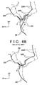
- FIG. 6A shows the outline of the result of computer aided engineering that was conducted on this embodiment under the same load conditions as in the comparative example that is shown in FIG. 6B .
- FIG. 6B shows the load that resists the deformation
- the angle ⁇ that is formed by the dash panel 22 and the front wall 28F, that is, the repetitive load (stress), can be smaller in the state after the deformation, which is indicated by solid lines, compared to that in the above comparative example.
- the imaginary lines in FIG 6A show the shape of the dash panel 22 and the cowl panel 28 before the transmission of load (deformation) as in the case with the comparative example that is shown in FIG. 6B .
- CAE computer aided engineering
- FEM finite element method
- the strength (fatigue strength) against separation of the portion where the stepped portion 22S is formed, at which stress is most likely to concentrate in a vehicle width direction, in the junction between the dash panel 22 and the cowl panel 28 can be improved.
- the installation of the patch 34 improves the rigidity of the vehicle body B against torsion during a turn or lane change of the automobile V.
- a portion of the dash panel 22 immediately below the junction Jcd between the front wall 28F of the cowl panel 28 and the upper end portion 22U of the dash panel 22, which are joined in a vehicle length direction, and a portion of the bottom wall 28B close to the front wall 28F are connected by the patch 34.
- the patch 34 which resists the separation of the junction Jcd between the dash panel 22 and the cowl panel 28 by tension, connects the dash panel 22 and the cowl panel 28 across the junction Jcd.
- the patch 34 effectively contributes to the improvement of the strength against the separation of the junction between the dash panel and cowl compared to a comparative example in which an upper end side is joined to the rear wall 28R of the cowl panel 28, for example.
- the patch 34 with the above configuration connects the dash panel 22 and the cowl panel 28 in a short distance, the angle 9 that is formed by the dash panel 22 and the front wall 28F, that is, repetitive load (stress), can be kept small by the patch 34, which is compact in size.
- the increase in mass of the vehicle body B can be significantly suppressed compared to a comparative example in which the thickness of the dash panel 22 and the cowl panel 28 is increased to improve their fatigue strength to an equivalent level. It has been confirmed from a result of computer aided engineering that the increase in weight by the addition of the patch has an advantage in terms of mass compared to a comparative example in which an equivalent fatigue strength is achieved by increasing the panel thickness.
- the rib 34R improves the strength of the patch 34 against deformation which tends to unfold (eliminate) the bend of the upper flange 34U relative to the patch main body 34M.
- the ridge lines RL3 and RL4 improve the strength of the patch 34 against deformation which tends to unfold (eliminate) the bend of the lower flange 34L relative to the patch main body 34M.
- the patch 34 is formed to have high rigidity against tension along a phantom straight line IL2 that connects an upper junction Ju and a lower main junction Jlm (refer to FIG 2 ), and is highly effective in improving the fatigue strength though it is compact in size.
- the fact that the deformation restricting portions of the upper and lower flanges 34U and 34L are formed separately is effective in reinforcing the bends and the patch main body 34M and contributes to a reduction in size of the patch 34.
- one edge (the right edge) of the patch main body 34M in a vehicle width direction is curved to prevent interference with other parts. Because the reinforcing flange 34F is erected along the patch main body 34M, the reinforcing flange 34F ensures that the patch main body 34M has sufficient strength against tension. In other words, the patch main body 34M is provided with sufficient strength against tension to contribute to the fatigue strength of the junction Jcd as described above.
- the reinforcing flange 34F continues to the right edge of the upper flange 34U, it also contributes to the improvement of the strength of the upper flange 34U against bend which tends to unfold the bend of the upper flange 34U relative to the patch main body 34M in conjunction with the rib 34R, which is described above.
- the stepped portion 22S has a plurality of (two) lower main junctions Jlm.
- the stress on each lower main junction Jlm can be reduced compared to the case where the stepped portion 22S has only one lower main junction Jlm.
- the load that is transmitted from a wheel to the junction between the dash panel 22 and the patch 34 is distributed to the plurality of lower main junctions Jlm, the stress on each lower main junction Jlm is reduced.
- the upper flange 34U of the patch 34 is secured to the cowl panel 28 at a plurality of upper junctions Ju.
- the load that is transmitted from a wheel to the junction between the cowl panel 28 and the patch 34 is distributed to the plurality of upper junctions Ju, and the stress on each upper junction Ju is reduced.
- the upper junctions Ju are located in the region in which the lower wall portion 30L of the cowl vibration-damping steel plate 30 is provided. This further reduces the stress which is applied to each upper junction Ju in conjunction with the effectiveness of the cowl vibration-damping steel plate 30 in reinforcing the cowl panel 28.
- the patch 34 is secured in place on the dash panel 22 at the two lower subsidiary junctions Jls, which are located on both sides of the stepped portion 22S in a vehicle width direction, before the patch 34 is secured to the dash panel 22 at the lower main junctions Jlm (in order to ensure strength).
- the lower flange 34L of the patch 34 can be secured in place without deviation (within an allowable range) relative to the stepped portion 22S as an inclined face of the dash panel 22.
- the patch 34 when properly secured to the dash panel 22 at the two lower main junctions Jim, contributes to the improvement of the fatigue strength of the junction Jcd between the dash panel 22 and the cowl panel 28 as described above.
- the two lower subsidiary junctions Jls are located on the extended leg portions 34P1 and 34P2 as leg portions that extend from the patch main body 34M in opposite directions along a vehicle width direction.
- the patch 34 can be secured in place on the dash panel 22 at both side of the stepped portion 22S of the dash panel 22 in a vehicle width direction without increasing the size of the patch 34 in a vehicle width direction.
- the patch main body 34M has two jig attachment holes 34Hj, the patch 34 is maintained in an appropriate position by a jig when transmitted to its installation location on the dash panel 22.
- the present invention is not limited thereto.
- the patch 34 may be provided at any location in a vehicle width direction where the stress which is applied to the junction Jcd in a vehicle width direction would be high without the patch 34.
- the patch 34 may be installed at the center in a vehicle width direction or on the driver side with respect to the center in a vehicle width direction.
- the (shape of the) reinforcing member in the present invention is not limited to the (shape of the) the patch 34.
- the reinforcing member may be of any shape depending on the shape of the dash panel 22 that is used in the automobile V and the shape and dimensions of components that are located behind the dash panel 22.
- a bearing surface portion which is formed by protruding or retracting, in a vehicle length direction, a part of the dash panel 22 in a vehicle width direction and is generally parallel to the general portion may be the portion between folded portions that are formed on both sides thereof in a vehicle width direction.
- the present invention is not limited thereto.
- at least one of the cowl vibration-damping steel plate 30 and the second dash panel 32 may not be provided.
Landscapes
- Engineering & Computer Science (AREA)
- Chemical & Material Sciences (AREA)
- Combustion & Propulsion (AREA)
- Transportation (AREA)
- Mechanical Engineering (AREA)
- Body Structure For Vehicles (AREA)
Description
- The present invention relates to a front structure for a vehicle in which a dash panel and a cowl are joined together.
- A configuration is known in which a first reinforcement that is arranged along the entire length of a cowl rear wall and a dash panel which is joined to the cowl front wall are coupled by a second reinforcement at the center in a vehicle width direction (refer to Japanese Utility Model Application Publication No.
5-46668 JP 5-46668 U 2009-113568 JP 2009-113568 A 2004-130976 JP 2004-130976 A - Because the junction where a dash panel and a cowl are joined in an overlapping relationship in a vehicle length direction undergoes deformation which tends to cause separation thereof by a force from a wheel, there is a room for improvement in terms of improvement of the strength against separation of the junction between the dash panel and cowl.
- In view of the above problem, the present invention provides a front structure for a vehicle which can improve the strength against separation of the junction where a dash panel and a cowl are joined in an overlapping relationship in a vehicle length direction. The solution envisaged for the above problem is represented by the matter of independent claim 1. The preamble features of said claim being taken from the disclosure of document
EP-A-0 426 107 . - According to one aspect of the present invention, a front structure for vehicle is provided which includes: a cowl panel which has at least a front wall and a bottom wall that extends from a lower end of the front wall toward a rear of the vehicle and which opens toward a top of the vehicle; a dash panel which has an upper end portion which is joined to the front wall of the cowl panel in an overlapping relationship in a vehicle length direction; and a reinforcing member which has a lower end side which is joined to the dash panel at a junction and an upper end side which is joined to the bottom wall of the cowl panel to form a closed cross-section in conjunction with the dash panel and the bottom wall.
- According to the front structure for a vehicle as described above, the reinforcing member connects the dash panel and the bottom wall of the cowl panel across the junction where the front wall of the cowl panel and upper end side of the dash panel are joined in an overlapping relationship in a vehicle length direction. In addition, the dash panel, the bottom wall and the reinforcing member form a closed cross-section as seen in a side view. In this configuration, a load which tends to cause separation of the junction where the dash panel and the cowl panel are overlapped in a vehicle length direction is restricted by tension of the reinforcing member. This prevents the junction from undergoing deformation which tends to cause separation thereof.
- As described above, the front structure for a vehicle as described above can improve the strength against separation of the junction where the dash panel and the cowl panel are overlapped in a vehicle length direction. Especially, because the reinforcing member is provided at a location in a vehicle width direction where the strength against separation would be relatively low without the reinforcing member, the strength against separation of the junction between the dash panel and the cowl panel can be efficiently improved compared to the case where a reinforcing member which extends, in a wide range in a vehicle width direction is provided.
- In the front structure for a vehicle, the dash panel may have a pair of folded portions that are formed apart from each other in a vehicle width direction, and the junction between the lower end side of the reinforcing member and the dash panel may include a plurality of main junctions that are located between the pair of folded portions of the dash panel.
- In a front structure for a vehicle as described above, the folded portions of the dash panel serve as high-rigidity portions and tend to transmit a force from a wheel to the junction with the cowl panel. In other words, a portion of the dash panel above the region between the pair of folded portions would have a relatively low strength against separation (tend to undergo stress concentration) without the reinforcing member. Because the lower end side of the reinforcing member is joined to the dash panel at the main junctions, which are located between the pair of folded portions, the reinforcing member, which is disposed locally in a vehicle width direction, can improve the strength against separation of the junction between the dash panel and the cowl panel. In addition, because the reinforcing member has a plurality of main junctions, the stress that is generated at the junction between the reinforcing member and the dash panel is reduced compared to a configuration with only one main junction.
- In a front structure for a vehicle as described above, the junction between the lower end side of the reinforcing member and the dash panel may include at least two subsidiary junctions, the pair of folded portions of the dash panel being sandwiched between the subsidiary junctions in a vehicle width direction.
- In a front structure for a vehicle as described above, since the pair of folded portion are sandwiched between the at least two subsidiary in a vehicle width direction, the subsidiary junctions help to prevent misalignment of the reinforcing member relative to the dash panel before joining of the main junctions. Thus, the main junctions can be properly joined at desired locations relative to the dash panel. This enables the main junctions to contribute to the improvement of the strength against separation of the junction between the dash panel and the cowl panel.
- In a front structure for a vehicle as described above, the subsidiary junctions may be formed on a pair of leg portions that extend from a lower end side of the reinforcing member in opposite directions along a vehicle width direction.
- In a front structure for a vehicle as described above, because the subsidiary junctions are formed on leg portions which extend from a lower portion of the reinforcing member, the subsidiary junctions can be located on both sides of a surface between the pair of folded portions without increasing the size of the reinforcing member.
- In a front structure for a vehicle as described above, the upper end side of the reinforcing member may be joined to the bottom wall of the cowl panel at a plurality of points.
- In a front structure for a vehicle as described above, because the reinforcing member is joined to the bottom wall of the cowl panel at a plurality of points, the stress that is generated at the junction between the reinforcing member and the cowl panel can be reduced compared to a configuration in which the bottom wall of the cowl panel is joined at only one point.
- In a front structure for a vehicle as described above, the reinforcing member may have a main body portion which forms a closed cross-section in conjunction with the dash panel and the bottom wall of the cowl panel and which has a first edge that linearly extends along a first end side thereof in a vehicle width direction between the dash panel and the bottom wall and a second edge that extends in an arcuate configuration as seen in a side view along a second end side thereof in a vehicle width direction between the dash panel and the bottom wall; and a reinforcing wall which protrudes in a vehicle length direction from the second edge.
- In a front structure for a vehicle as described above, the reinforcing member has a first edge that extends between the dash panel and the bottom wall of the cowl panel linearly and a second edge that extends between the dash panel and the bottom wall of the cowl panel in an arcuate configuration (to be convex either forward or rearward) as seen in a side view. Thus, the distance from the reinforcing member to the dash panel and the cowl panel is greater or smaller on the second edge side than on the first edge side. The reinforcing member can therefore be prevented from interfering with other components. The second edge, which has an arcuate configuration, may be disadvantageous in terms of strength against tension, but is reinforced against tension by the reinforcing wall, which protrudes from the second edge in a vehicle length direction. Thus, the second edge can help the reinforcing member to exhibit a desired reinforcing effect.
- In a front structure for a vehicle as described above, the reinforcing member may include a main body portion which forms a closed cross-section in conjunction with the dash panel and the bottom wall of the cowl panel; a lower flange which is bent at a lower end of the main body portion and which extends along a back side of the dash panel and is joined to the dash panel; an upper flange that is bent at an upper end of the main body portion and which extends along a lower face of the bottom wall and is joined to the bottom wall; a lower restricting portion that restricts deformation which tends to increase a bend angle between the main body portion and the lower flange; and an upper restricting portion that restricts deformation which tends to increase a bend angle between the main body portion and the upper flange.
- In a front structure for a vehicle as described above, a bend is formed between the main body portion and the upper flange and between the main body portion and the lower flange of the reinforcing member, and the reinforcing member undergoes deformation which tends to increase the bend angles of the bends (to unfold the bends) when a tensile load is applied to the reinforcing member. The reinforcing member has an upper restricting portion between the main body portion and the upper flange and a lower restricting portion between the main body portion and the lower flange. Thus, deformation which tends to unfold the upper and lower bends of the reinforcing member is restricted (limited), and the reinforcing member can effectively resist separation of the junction between the dash panel and the cowl panel by tension.
- In a front structure for a vehicle as described above, the main body portion of the reinforcing member, which forms a closed cross-section in conjunction with the dash panel and the cowl panel, may have a plurality of openings.
- In a front structure for a vehicle as described above, the main body portion of the reinforcing member has a plurality of openings that can be used to maintain the reinforcing member in a desired position. In other words, the reinforcing member can be joined to the dash panel and the cowl panel in an appropriate position relative to the dash panel and the cowl panel. Thus, the main junctions can be properly joined in a desired position relative to the dash panel. This enables the main junctions to contribute to the improvement of the strength against separation of the junction between the dash panel and the cowl panel.
- As described in the foregoing, the front structure for a vehicle of the present invention is highly effective in improving the strength against separation of the junction where the dash panel and the cowl panel are overlapped in a vehicle length direction.
- Features, advantages, and technical and industrial significance of exemplary embodiments of the invention will be described below with reference to the accompanying drawings, in which like numerals denote like elements, and wherein:
-
-
FIG. 1 is a perspective view of an essential part of a vehicle body front structure according to an embodiment of the present invention as seen from the rear of a vehicle; -
FIG 2 is a sectional side elevation that illustrates an essential part of the vehicle body front structure according to the embodiment of the present invention; -
FIG 3 is a perspective view of a front right part of an automobile to which a front structure for a vehicle according to the embodiment of the present invention is applied as seen from the front of the vehicle; -
FIG. 4 is a front view that illustrates the front structure for a vehicle according to the embodiment of the present invention; -
FIG 5 is a perspective view that illustrates only a patch that constitutes the front structure for a vehicle according to the embodiment of the present invention; -
FIG. 6A is a diagrammatic drawing that illustrates the result of a computer aided engineering of the state of the front structure for a vehicle according to the embodiment of the present invention that is deformed by a force from a front wheel; and -
FIG. 6B is a diagrammatic drawing that illustrates the result of a computer aided engineering of the state of a front structure for a vehicle according to a comparative example as a related art that is deformed by a force from a front wheel. - Description is hereinafter made of a vehicle
body front structure 10 as a front structure for a vehicle according to a first embodiment of the present invention with reference toFIG 1 to FIGs. 6A and6B . The arrow FR, the arrow UP, the arrow RH and the arrow LH, which are shown as needed in the drawings, indicates the forward (traveling) direction along the vehicle length direction, the upward direction along the vehicle height direction, the right side with respect to the traveling direction (one side with respect to a vehicle width direction), and the left side with respect to the traveling direction (the other side with respect to a vehicle width direction), respectively. In the following description, the terms "front" and "rear," "upper" and "lower," and "right" and "left" refer to the front and rear sides in the vehicle length direction, the upper and lower sides in the vehicle height direction, and the right and left sides with respect to the traveling direction of the vehicle, respectively, unless otherwise noted. -
FIG 3 is a perspective view that illustrates a part of the right side of a vehicle body B of an automobile V to which the vehiclebody front structure 10 is applied. Because the vehicle body B is basically formed in a generally bilaterally symmetric fashion except the parts that are described later, the right side (the passenger side in this embodiment) of the vehicle body B is primarily described in the following description. As shown inFIG 3 , the vehicle body B includes afront pillar 12, an apronupper member 14 that extends forward from a vertical intermediate portion of thefront pillar 12, and anapron panel 16 that extends downward from the apronupper member 14. Afront suspension tower 18 to which an upper end of a front suspension (not shown) is coupled is integrally formed with theapron panel 16, which constitutes the vehicle body B. - The vehicle body B also includes a
front side member 20 as a skeletal member which extends in a vehicle length direction. One end side of a bumper reinforcement in a vehicle width direction is coupled to a front end (not shown) of thefront side member 20. Thefront side member 20 includes afront portion 20F that extends in a vehicle length direction in an engine room E, akick portion 20K which is curved along adash panel 22, which is described later, and arear portion 20R which forms a skeleton that is elongated in a vehicle length direction in conjunction with a floor panel (not shown) behind thekick portion 20K. Thefront portion 20F of thefront side member 20 has a rear portion which is joined to an inner portion of thefront suspension tower 18 in a vehicle width direction. - The vehicle body B also includes a
dash panel 22 which separates the engine room E and a cabin C. Thedash panel 22 has a lower end side which is joined to a front end of a floor panel (not shown) along the almost entire length thereof in a vehicle width direction. Adash cross member 24 which forms a skeletal structure with a closed cross-section in conjunction with thedash panel 22 is joined to a front side of thedash panel 22 along the almost entire length thereof in a vehicle width direction. Thefront portion 20F of thefront side member 20 has a rear end which is joined in an abutting relationship with thedash cross member 24. Thekick portion 20K of thefront side member 20 is joined to a front face of thedash panel 22 and continues to therear portion 20R, which is joined to a lower face of the floor panel. - The
dash panel 22 has an upper end side to which acowl panel 28 that constitutes acowl member 26 is joined. Thecowl panel 28, which is a member that has an inverted hat-like cross-section that opens upward and is elongated in a vehicle width direction, extends between vertical intermediate portions of right and leftfront pillars 12. Thecowl panel 28 has longitudinal ends which are joined to a corresponding one of right and left apronupper members 14. Thecowl member 26 including thecowl panel 28 is configured to support a windshield glass in conjunction with the right and leftfront pillars 12 and a roof head member (not shown). - In the vehicle body B as described above, the load from a front wheel (front suspension) is transmitted to the junction between the
dash panel 22 and thecowl panel 28 as a load which tends to cause separation thereof via thefront suspension tower 18 and thefront pillar 12. The transmission of load is described later in connection with the effects of this embodiment. - The essential features of the vehicle
body front structure 10 are described in detail below. - As shown in
FIG. 2 , thecowl panel 28 includes, as essential components, afront wall 28F and arear wall 28R which are opposed to each other in a vehicle length direction, and abottom wall 28B which connects lower ends of thefront wall 28F and therear wall 28R. Thus, thecowl panel 28 opens upward as described above. At a lower front part of thecowl panel 28, a cowl vibration-dampingsteel plate 30 with a generally L-shaped configuration as seen in a side view is joined to a lower portion of thefront wall 28F and a front portion of thebottom wall 28B by, for example, spot welding. More specifically, the cowl vibration-dampingsteel plate 30 includes, as essential components, afront wall portion 30F which is joined to thefront wall 28F, and alower wall portion 30L which is joined to thebottom wall 28B. - The
dash panel 22 has anupper end portion 22U which is joined to thefront wall 28F of thecowl panel 28 in an overlapping relationship in a vehicle length direction. In this embodiment, theupper end portion 22U of thedash panel 22 and a lower portion of thefront wall 28F of thecowl panel 28 are joined to each other along the almost entire length thereof in a vehicle width direction via thefront wall portion 30F of the cowl vibration-dampingsteel plate 30 at a junction Jcd. The junction Jcd in this embodiment is formed by integrally joining thefront wall portion 30F, thefront wall 28F, and theupper end portion 22U, which are overlapped in a vehicle length direction, by spot welding. - The
dash panel 22, which is joined to thecowl panel 28 at theupper end portion 22U as described above, is bilaterally asymmetric because of the difference in shape of the cabin C and the engine room E between the driver side and passenger side. As shown inFIG 4 , thedash panel 22 has a steppedportion 22S in a region A between the center line CL in a vehicle width direction as seen in a front view and aspot 18C where the rightfront suspension tower 18 is coupled to a front suspension (phantom line IL1). In other words, the steppedportion 22S is offset with respect to the center of the vehicle body B in a vehicle width direction. The steppedportion 22S serves as an inclined vertical wall which connects ageneral portion 22G of thedash panel 22 and abearing surface portion 22Z that protrudes forward farther than thegeneral portion 22G - Thus, a first ridge line RL1 which serves as a boundary with the bearing
surface portion 22Z is formed on the right side of the steppedportion 22S, and a second ridge line RL2 which serves as a boundary with thegeneral portion 22G is formed on the left side of the steppedportion 22S. Thedash panel 22 is formed by press working, and the first ridge line RL1 and the second ridge line RL2 are one example of a pair of folded portions. In this embodiment, the bearingsurface portion 22Z of thedash panel 22 has a throughhole 22H that extends through thedash panel 22 at a location close to the steppedportion 22S. - As shown in
FIG. 1 , thedash panel 22 in this embodiment is covered with asecond dash panel 32 from the back side. Thesecond dash panel 32 is joined to thedash panel 22 to reinforce thedash panel 22. Although not shown entirely, thesecond dash panel 32 is configured to cover thedash panel 22 generally entirely from the back side except an upper part of the steppedportion 22S and a portion around the throughhole 22H of the bearingsurface portion 22Z. - The vehicle body front structure 10 (the vehicle body B) has a
patch 34 as a reinforcing member that couples thedash panel 22 and thecowl panel 28 at a fixed location in the region A as seen in a front view. Specifically, thepatch 34 extends between the steppedportion 22S of thedash panel 22 and thebottom wall 28B of thecowl panel 28 as shown inFIG. 1 andFIG 4 . In this embodiment, thepatch 34 has alower flange 34L that forms a lower part thereof and is joined to the steppedportion 22S of thedash panel 22, and anupper flange 34U that forms an upper part thereof and is joined to a front portion of thebottom wall 28B of thecowl panel 28. - A patch
main body 34M of thepatch 34 as a main body portion between thelower flange 34L and theupper flange 34U forms a closed cross-sectional portion CS which has a generally triangular shape as seen in a side view in conjunction with thedash panel 22 and thebottom wall 28B of thecowl panel 28 as shown inFIG. 2 . In other words, the patchmain body 34M is separated from thedash panel 22 and thecowl panel 28. Thepatch 34 and its joint (coupling) structure are described in more detail below. - As shown in
FIG. 5 , the patchmain body 34M, which has a plate-like configuration, has a liner left edge 34EL which is slightly inclined with respect to a vehicle height direction, and an arcuate right edge 34ER which is curved to be convex rearward as seen in a side view. A reinforcingflange 34F as a reinforcing wall extends rearward from the curved right edge 34ER of the patchmain body 34M. Thus, the right edge 34ER of the patchmain body 34M is reinforced in a vehicle height (tensile) direction by the reinforcingflange 34F. The patchmain body 34M has an attachment datum hole 34Hs into which a datum pin of a welding apparatus is inserted when thepatch 34 is joined to the vehicle body B, and a pair of jig attachment holes 34Hj as a plurality of openings that are used to maintain the attachment position of thepatch 34 relative to the vehicle body B. - The
upper flange 34U is formed by bending an upper end of the patchmain body 34M rearward, and is joined to thebottom wall 28B at two upper junctions Ju that are arranged at right and left ends thereof as shown inFIG. 1 . In this embodiment, thepatch 34 has arib 34R, at the center in its width direction, as an upper restricting portion which is formed across the boundary between theupper flange 34U and an upper end portion of the patchmain body 34M and protrudes rearward. Thus, thepatch 34 is reinforced against deformation which tends to increase the bend angle (tends to eliminate (unfold) the bend) between the patchmain body 34M and theupper flange 34U compared to a configuration without therib 34R. In this embodiment, the reinforcingflange 34F is connected to the right edge 34ER of theupper flange 34U. - The
lower flange 34L is formed by bending a lower end of the patchmain body 34M rearward, and joined to the steppedportion 22S at two, upper and lower, lower main junctions Jlm as a plurality of main junctions that are shown inFIG. 1 . The lower main junctions Jlm are configured to ensure the joint strength between a lower portion of thepatch 34 and thedash panel 22. - A pair of extended leg portions 34P1 and 34P2 as leg portions extend laterally in opposite directions from a lower portion of the patch
main body 34M of thepatch 34, that is, thelower flange 34L. The extended leg portion 34P1, which extends rightward, extends farther rightward than a lower portion of the reinforcingflange 34F and is joined to a back side of the bearingsurface portion 22Z of thedash panel 22 at a lower subsidiary junction Jls as a subsidiary junction that is located near its extended end. The extended leg portion 34P2, which extends farther leftward from a lower portion of the patchmain body 34M and a left end of thelower flange 34L, is joined to a back side of thegeneral portion 22G of thedash panel 22 at a lower subsidiary junction Jls as a subsidiary junction that is located near its extended end. - In this embodiment, the extended leg portion 34P2 is joined to the
dash panel 22 via thesecond dash panel 32 at the lower subsidiary junction Jls. The right and left lower subsidiary junctions Jls are joined at locations on both sides of the steppedportion 22S (the patchmain body 34M) of thedash panel 22 in a vehicle width direction before the lower main junctions Jlm are joined so that the deviation of the coupling location of a lower portion of thepatch 34 can be within an acceptable range relative to thedash panel 22. - The extended leg portion 34P2 forms a ridge line (folded portion) RL3 which is convex upward along the boundary with the
lower flange 34L, and forms a ridge line (folded portion) RL4 which is convex rearward along the boundary with a lower portion of the patchmain body 34M. Thus, thepatch 34 is reinforced against deformation which tends to increase the bend angle (to eliminate (unfold) the bend) between the patchmain body 34M and thelower flange 34L (and the extended leg portion 34P2) compared to a configuration without the ridge lines RL3 and RL4. The ridge line RL3 along the boundary between the extended leg portion 34P2 and thelower flange 34L and the ridge line RL4 along the boundary between the extended leg portion 34P2 and a lower portion of the patchmain body 34M as described above are one example of lower restricting portions. - The junctions where the
patch 34 is joined to thedash panel 22 and thecowl panel 28 as described above are formed by spot welding. The joint may be made by means of bolts and nuts instead of welding. - In the vehicle
body front structure 10, components CP, such as a dash inner silencer (insulator), an air-conditioning unit (HVAC) and a wire harness, are disposed in a cabin C side space including the location where thepatch 34 is joined to thedash panel 22 as shown inFIG. 2 . The patchmain body 34M of thepatch 34 has a curved right edge as described above in order to avoid interference with the components CP (including the range of movement of movable components, such as the wire harness). - (Process of installing patch 34) In the vehicle
body front structure 10, thedash panel 22 is assembled to the vehicle body B before thecowl member 26 is assembled to the vehicle body B when the vehicle body B is assembled, and, in this state, thepatch 34 is secured to thedash panel 22 at the two lower subsidiary junctions Jls. Next, thepatch 34 is secured to the steppedportion 22S of thedash panel 22 at the two lower main junctions Jlm. Then, after thecowl member 26 is assembled to the vehicle body B, thepatch 34 is secured to thebottom wall 28B of thecowl panel 28 through the cowl vibration-dampingsteel plate 30 at the upper junctions Ju in the final assembly step. - During the assembly, the
patch 34 is attached to a jig at the two jig attachment holes 34Hj of the patchmain body 34M and held in proper position relative to thedash panel 22. For example, thepatch 34 is attached to a jig on a hand of an assembling robot at the jig attachment holes 34Hj and transported by the robot to (inserted into) a desired location in the vehicle body B during assembly. When thepatch 34 is transported to a desired location relative to the dash panel 22 (the vehicle body B), a welding datum pin is inserted into the attachment datum hole 34Hs, and, in this state, thepatch 34 is secured in place at the lower subsidiary junctions Jls as described above. - The effects of the first embodiment are next described.
- When an automobile travels on a rough road, for example, a large vertical load is applied to the front suspensions. In particular, in automobiles with a large unsprung mass, such as vehicles which use large diameter tires on the front wheels, or automobiles with a large sprung mass, such as hybrid vehicles which have a heavy battery, a large load tends to be transmitted from the front suspensions to the vehicle body B.
- In an automobile to which the vehicle
body front structure 10 with the above configuration is applied, when a large downward load is transmitted from a front suspension to the front suspension tower 18 (refer to the arrow Fd inFIG. 3 ), thefront portion 20F of thefront side member 20, which is joined to thefront suspension tower 18, is forced downward. Thus, a moment M is generated around the junction where a rear end of thefront portion 20F is joined to thedash cross member 24, and thedash panel 22 is pulled forward by the moment M. - Then, the junction Jcd, where the
upper end portion 22U of thedash panel 22 and thefront wall 28F of thecowl panel 28 are joined in an overlapping relationship in a vehicle length direction by spot welding undergoes deformation (stress) which tends to cause separation thereof. Especially, the deformation (in a vehicle length direction) which tends to cause separation of the junction Jcd tends to be large when the right and left front wheels are moved in vertically opposite phases. - The stepped
portion 22S of thedash panel 22, in other words, the portion between the two ridge lines RL1 and RL2, serves as a high-rigidity region. Thus, a load (deformation) toward the front of the vehicle which is caused by the moment M is transmitted to the junction Jcd along a phantom straight line that connects thefront side member 20 and the steppedportion 22S. In other words, because the load which is caused by the moment M is less likely to be absorbed (attenuated) by deformation of the panel on the routes along the two ridge lines RL1 and RL2 (the steppedportion 22S) than on a route through any other portion, a larger load is transmitted to the junction Jcd along the ridge lines RL1 and RL2 than along any other portion. In other words, the deformation which tends to cause separation of the junction Jcd is larger at the location where the steppedportion 22S is formed than at any other portion of thedash panel 22 in a vehicle width direction. It was confirmed by computer aided engineering that high stress is applied to a region Z including spot welding points S1 to S3 that are shown inFIG 4 in a comparative example without thepatch 34. - Thus, in a comparative example without the
patch 34, the degree of deformation at the junction Jcd which tends to cause separation thereof in a deformed state, which is indicated by solid lines, with respect to the shape before the transmission of the load (deformation), which is indicated by imaginary lines, will be large as shown inFIG. 6B . Specifically, the angle θ that is formed by thedash panel 22 and thefront wall 28F, in other words, repetitive load (stress), becomes large. When the thickness of the steel plates that form thedash panel 22 and thecowl panel 28 is increased to obtain a fatigue strength that is sufficiently high to prevent the separation of the spot welding at the junction Jcd (to reduce the stress that is applied to the junction Jcd) as a countermeasure against this problem, the mass of the vehicle body B increases. - In the vehicle
body front structure 10, thepatch 34 is provided on a portion of thedash panel 22 where the deformation, that is, stress, that tends to cause separation of the junction Jcd will be the largest. Thus, the deformation which tends to cause separation of thedash panel 22 and thefront wall 28F is restricted (a load that resists the deformation is supported) by tension of thepatch 34 in a generally vehicle height direction.FIG 6A shows the outline of the result of computer aided engineering that was conducted on this embodiment under the same load conditions as in the comparative example that is shown inFIG. 6B . In this embodiment, as shown inFIG. 6A , the angle θ that is formed by thedash panel 22 and thefront wall 28F, that is, the repetitive load (stress), can be smaller in the state after the deformation, which is indicated by solid lines, compared to that in the above comparative example. The imaginary lines inFIG 6A show the shape of thedash panel 22 and thecowl panel 28 before the transmission of load (deformation) as in the case with the comparative example that is shown inFIG. 6B . - It was confirmed by computer aided engineering (CAE), such as a finite element method (FEM), that the stress that is applied to the spot welding points in the junction Jcd immediately above the stepped
portion 22S is reduced in this embodiment. More specifically, an analysis result that the stress that is applied to the spot welding points S1 to S3 immediately above the steppedportion 22S that are shown inFIG. 4 is reduced was obtained. - As described above, in the vehicle
body front structure 10 according to this embodiment, the strength (fatigue strength) against separation of the portion where the steppedportion 22S is formed, at which stress is most likely to concentrate in a vehicle width direction, in the junction between thedash panel 22 and thecowl panel 28 can be improved. In addition, the installation of thepatch 34 improves the rigidity of the vehicle body B against torsion during a turn or lane change of the automobile V. - Especially, in the vehicle
body front structure 10, a portion of thedash panel 22 immediately below the junction Jcd between thefront wall 28F of thecowl panel 28 and theupper end portion 22U of thedash panel 22, which are joined in a vehicle length direction, and a portion of thebottom wall 28B close to thefront wall 28F are connected by thepatch 34. In other words, a structure is formed in which thepatch 34, which resists the separation of the junction Jcd between thedash panel 22 and thecowl panel 28 by tension, connects thedash panel 22 and thecowl panel 28 across the junction Jcd. Thus, thepatch 34 effectively contributes to the improvement of the strength against the separation of the junction between the dash panel and cowl compared to a comparative example in which an upper end side is joined to therear wall 28R of thecowl panel 28, for example. - In addition, because the
patch 34 with the above configuration connects thedash panel 22 and thecowl panel 28 in a short distance, the angle 9 that is formed by thedash panel 22 and thefront wall 28F, that is, repetitive load (stress), can be kept small by thepatch 34, which is compact in size. Thus, the increase in mass of the vehicle body B can be significantly suppressed compared to a comparative example in which the thickness of thedash panel 22 and thecowl panel 28 is increased to improve their fatigue strength to an equivalent level. It has been confirmed from a result of computer aided engineering that the increase in weight by the addition of the patch has an advantage in terms of mass compared to a comparative example in which an equivalent fatigue strength is achieved by increasing the panel thickness. - Especially, the
rib 34R improves the strength of thepatch 34 against deformation which tends to unfold (eliminate) the bend of theupper flange 34U relative to the patchmain body 34M. In addition, the ridge lines RL3 and RL4 improve the strength of thepatch 34 against deformation which tends to unfold (eliminate) the bend of thelower flange 34L relative to the patchmain body 34M. In other words, thepatch 34 is formed to have high rigidity against tension along a phantom straight line IL2 that connects an upper junction Ju and a lower main junction Jlm (refer toFIG 2 ), and is highly effective in improving the fatigue strength though it is compact in size. In addition, the fact that the deformation restricting portions of the upper andlower flanges main body 34M and contributes to a reduction in size of thepatch 34. - In addition, especially in the vehicle
body front structure 10, one edge (the right edge) of the patchmain body 34M in a vehicle width direction is curved to prevent interference with other parts. Because the reinforcingflange 34F is erected along the patchmain body 34M, the reinforcingflange 34F ensures that the patchmain body 34M has sufficient strength against tension. In other words, the patchmain body 34M is provided with sufficient strength against tension to contribute to the fatigue strength of the junction Jcd as described above. Because the reinforcingflange 34F continues to the right edge of theupper flange 34U, it also contributes to the improvement of the strength of theupper flange 34U against bend which tends to unfold the bend of theupper flange 34U relative to the patchmain body 34M in conjunction with therib 34R, which is described above. - In the vehicle
body front structure 10, the steppedportion 22S has a plurality of (two) lower main junctions Jlm. Thus, the stress on each lower main junction Jlm can be reduced compared to the case where the steppedportion 22S has only one lower main junction Jlm. In other words, because the load that is transmitted from a wheel to the junction between thedash panel 22 and thepatch 34 is distributed to the plurality of lower main junctions Jlm, the stress on each lower main junction Jlm is reduced. - Similarly, the
upper flange 34U of thepatch 34 is secured to thecowl panel 28 at a plurality of upper junctions Ju. Thus, the load that is transmitted from a wheel to the junction between thecowl panel 28 and thepatch 34 is distributed to the plurality of upper junctions Ju, and the stress on each upper junction Ju is reduced. Especially, in this embodiment, the upper junctions Ju are located in the region in which thelower wall portion 30L of the cowl vibration-dampingsteel plate 30 is provided. This further reduces the stress which is applied to each upper junction Ju in conjunction with the effectiveness of the cowl vibration-dampingsteel plate 30 in reinforcing thecowl panel 28. - In addition, in the vehicle
body front structure 10, thepatch 34 is secured in place on thedash panel 22 at the two lower subsidiary junctions Jls, which are located on both sides of the steppedportion 22S in a vehicle width direction, before thepatch 34 is secured to thedash panel 22 at the lower main junctions Jlm (in order to ensure strength). Thus, thelower flange 34L of thepatch 34 can be secured in place without deviation (within an allowable range) relative to the steppedportion 22S as an inclined face of thedash panel 22. Thus, thepatch 34, when properly secured to thedash panel 22 at the two lower main junctions Jim, contributes to the improvement of the fatigue strength of the junction Jcd between thedash panel 22 and thecowl panel 28 as described above. - In addition, the two lower subsidiary junctions Jls are located on the extended leg portions 34P1 and 34P2 as leg portions that extend from the patch
main body 34M in opposite directions along a vehicle width direction. Thus, in the vehiclebody front structure 10, thepatch 34 can be secured in place on thedash panel 22 at both side of the steppedportion 22S of thedash panel 22 in a vehicle width direction without increasing the size of thepatch 34 in a vehicle width direction. - In addition, because the patch
main body 34M has two jig attachment holes 34Hj, thepatch 34 is maintained in an appropriate position by a jig when transmitted to its installation location on thedash panel 22. - While an example in which the
patch 34 is installed in the region A between the center of the vehicle body B in a vehicle width direction and the right (passenger side)front suspension tower 18 is shown in the above embodiment, the present invention is not limited thereto. Thepatch 34 may be provided at any location in a vehicle width direction where the stress which is applied to the junction Jcd in a vehicle width direction would be high without thepatch 34. Thus, thepatch 34 may be installed at the center in a vehicle width direction or on the driver side with respect to the center in a vehicle width direction. - In addition, the (shape of the) reinforcing member in the present invention is not limited to the (shape of the) the
patch 34. For example, the reinforcing member may be of any shape depending on the shape of thedash panel 22 that is used in the automobile V and the shape and dimensions of components that are located behind thedash panel 22. - In addition, while an example in which the stepped
portion 22S as an inclined vertical wall is formed between a pair of folded portions of thedash panel 22 is shown in the above embodiment, the present invention is not limited thereto. For example, a bearing surface portion which is formed by protruding or retracting, in a vehicle length direction, a part of thedash panel 22 in a vehicle width direction and is generally parallel to the general portion may be the portion between folded portions that are formed on both sides thereof in a vehicle width direction. - In addition, while an example in which the vehicle body B is provided with the cowl vibration-damping
steel plate 30 and thesecond dash panel 32 is shown in the above embodiment, the present invention is not limited thereto. For example, at least one of the cowl vibration-dampingsteel plate 30 and thesecond dash panel 32 may not be provided.
Claims (6)
- A front structure for a vehicle, comprising:a cowl panel (28) which has at least a front wall (28F) and a bottom wall (28B) that extends from a lower end of the front wall (28F) toward a rear of the vehicle and which opens toward a top of the vehicle;a dash panel (22) which has an upper end portion which is joined to the front wall (28F) of the cowl panel (28) in an overlapping relationship in a vehicle length direction; anda reinforcing member (34) which has a lower end side which is joined to the dash panel (22) at a junction and an upper end side which is joined to the bottom wall (28B) of the cowl panel (28) to form a closed cross-section in conjunction with the dash panel (22) and the bottom wall (28B),wherein the dash panel (22) has a pair of folded portions (RL1 and RL2) that are formed apart from each other in a vehicle width direction, and the junction between the lower end side of the reinforcing member (34) and the dash panel (22) includes a plurality of main junctions (Jlm) that are located between the pair of folded portions (RL1 and RL2) of the dash panel (22), characterized in that,the junction between the lower end side of the reinforcing member (34) and the dash panel (22) includes at least two subsidiary junctions (Jls), the pair of folded portions (RL1 and RL2) of the dash panel (22) being sandwiched between the subsidiary junctions (Jls) in a vehicle width direction,the front wall (28F) of the cowl panel (28) and the dash panel (22) are joined along a vehicle width direction;the upper end side of the reinforcing member is joined to the cowl panel (28) at at least two portions which are located at different positions along the vehicle width direction;and the reinforcing member has a main body portion (34M) which forms a closed cross-section in conjunction with the dash panel (22) and the bottom wall (28B) of the cowl panel (28) in a vehicle width direction.
- The front structure for a vehicle according to claim 1, wherein the subsidiary junctions (Jls) are formed on a pair of leg portions (34P1 and 34P2) that extend from a lower end side of the reinforcing member (34) in opposite directions along a vehicle width direction.
- The front structure for a vehicle according to claim 1 or 2, wherein the upper end side of the reinforcing member (34) is joined to the bottom wall (28B) of the cowl panel (28) at a plurality of points (Ju).
- The front structure for a vehicle according to claim 1, wherein the main body portion (34M) has a first edge (34EL) that linearly extends along a first end side thereof in a vehicle width direction between the dash panel (22) and the bottom wall (28B) and a second edge (34ER) that extends in an arcuate configuration as seen in a side view along a second end side thereof in a vehicle width direction between the dash panel (22) and the bottom wall (28B); and a reinforcing wall (34F) which protrudes in a vehicle length direction from the second edge (34ER).
- The front structure for a vehicle according to claim 1, wherein the reinforcing member (34) further includes a lower flange (34L) which is bent at a lower end of the main body portion (34M) and which extends along a back side of the dash panel (22) and is joined to the dash panel (22); an upper flange (34U) that is bent at an upper end of the main body portion (34M) and which extends along a lower face of the bottom wall (28B) and is joined to the bottom wall (28B); a lower restricting portion (RL3, RL4) that restricts deformation which tends to increase a bend angle between the main body portion (34M) and the lower flange (34L); and an upper restricting portion (34R) that restricts deformation which tends to increase a bend angle between the main body portion (34M) and the upper flange (34U).
- The front structure for a vehicle according to claim 1, wherein the main body portion (34M) of the reinforcing member (34), which forms a closed cross-section in conjunction with the dash panel (22) and the cowl panel (28), has a plurality of openings (34Hj).
Applications Claiming Priority (2)
| Application Number | Priority Date | Filing Date | Title |
|---|---|---|---|
| JP2011174871A JP5664497B2 (en) | 2011-08-10 | 2011-08-10 | Vehicle front structure |
| PCT/IB2012/001384 WO2013021246A1 (en) | 2011-08-10 | 2012-07-16 | Front structure for vehicle |
Publications (2)
| Publication Number | Publication Date |
|---|---|
| EP2741952A1 EP2741952A1 (en) | 2014-06-18 |
| EP2741952B1 true EP2741952B1 (en) | 2015-04-08 |
Family
ID=46650829
Family Applications (1)
| Application Number | Title | Priority Date | Filing Date |
|---|---|---|---|
| EP20120746118 Not-in-force EP2741952B1 (en) | 2011-08-10 | 2012-07-16 | Front structure for vehicle |
Country Status (7)
| Country | Link |
|---|---|
| US (1) | US9096274B2 (en) |
| EP (1) | EP2741952B1 (en) |
| JP (1) | JP5664497B2 (en) |
| KR (1) | KR101503225B1 (en) |
| CN (1) | CN103796908B (en) |
| RU (1) | RU2554174C1 (en) |
| WO (1) | WO2013021246A1 (en) |
Families Citing this family (10)
| Publication number | Priority date | Publication date | Assignee | Title |
|---|---|---|---|---|
| CN104340278A (en) * | 2013-08-07 | 2015-02-11 | 一汽海马汽车有限公司 | Car front wall upper plate assembly and car |
| KR101526398B1 (en) * | 2013-12-18 | 2015-06-05 | 현대자동차 주식회사 | Cowl cross member mounting assembly for vehicle |
| JP6300024B2 (en) * | 2014-08-01 | 2018-03-28 | マツダ株式会社 | Front body structure of the vehicle |
| JP6112083B2 (en) * | 2014-08-21 | 2017-04-12 | トヨタ自動車株式会社 | Body front structure |
| KR101534751B1 (en) * | 2014-09-30 | 2015-07-07 | 현대자동차 주식회사 | Vehicle body reinforcing structure for coping with front collision |
| JP6870533B2 (en) * | 2017-08-23 | 2021-05-12 | 株式会社オートネットワーク技術研究所 | Assembly structure of wire harness with electrical parts and wire harness with electrical parts |
| JP7172723B2 (en) * | 2019-02-26 | 2022-11-16 | トヨタ自動車株式会社 | vehicle front structure |
| JP7060557B2 (en) * | 2019-09-04 | 2022-04-26 | 本田技研工業株式会社 | Front structure of the car body |
| CN113139240A (en) * | 2021-04-29 | 2021-07-20 | 奇瑞汽车股份有限公司 | Welding spot failure simulation method |
| WO2023228238A1 (en) * | 2022-05-23 | 2023-11-30 | トヨタ車体株式会社 | Front structure for vehicle |
Family Cites Families (24)
| Publication number | Priority date | Publication date | Assignee | Title |
|---|---|---|---|---|
| SU996253A1 (en) * | 1981-07-17 | 1985-02-15 | Ордена Октябрьской Революции И Ордена Трудового Красного Знамени Автомобильный Завод Им.Ленинского Комсомола Производственного Объединения "Москвич" | Vehicle body |
| DE69009002T2 (en) * | 1989-10-31 | 1994-09-01 | Mazda Motor | Vehicle front body construction. |
| DE4040731C2 (en) * | 1989-12-21 | 1996-02-29 | Mazda Motor | Mounting arrangement for the cockpit area of motor vehicles |
| JP2798467B2 (en) * | 1990-02-27 | 1998-09-17 | マツダ株式会社 | Vehicle body front structure and vehicle body assembling method |
| JP2549257Y2 (en) * | 1991-12-03 | 1997-09-30 | トヨタ車体株式会社 | Body front structure |
| JP2000108938A (en) * | 1998-09-30 | 2000-04-18 | Fuji Heavy Ind Ltd | Front body construction of automobile |
| JP3640637B2 (en) * | 2001-12-10 | 2005-04-20 | 本田技研工業株式会社 | Seal structure for vehicle cowl top panel |
| US7000726B2 (en) * | 2002-04-26 | 2006-02-21 | Mazda Motor Corporation | Engine positioning structure for an automobile |
| JP4152162B2 (en) | 2002-10-11 | 2008-09-17 | ダイハツ工業株式会社 | Auto body front structure |
| JP2005206109A (en) * | 2004-01-26 | 2005-08-04 | Toyota Motor Corp | Vehicle body front structure |
| JP4872586B2 (en) * | 2005-11-10 | 2012-02-08 | 日産自動車株式会社 | Car body front structure and connecting member |
| JP4233053B2 (en) * | 2006-04-27 | 2009-03-04 | 本田技研工業株式会社 | Body front structure |
| JP4825640B2 (en) * | 2006-11-10 | 2011-11-30 | 本田技研工業株式会社 | Auto body structure |
| JP4935363B2 (en) * | 2007-01-09 | 2012-05-23 | マツダ株式会社 | Front body structure of automobile |
| JP2009113568A (en) | 2007-11-03 | 2009-05-28 | Kanto Auto Works Ltd | Front part structure for automobile |
| JP5163083B2 (en) * | 2007-12-05 | 2013-03-13 | マツダ株式会社 | Front body structure of automobile |
| JP5104367B2 (en) * | 2008-02-08 | 2012-12-19 | トヨタ自動車株式会社 | Body front structure |
| WO2011043134A1 (en) * | 2009-10-09 | 2011-04-14 | 本田技研工業株式会社 | Structure for front section of vehicle body |
| JP5504820B2 (en) * | 2009-10-26 | 2014-05-28 | マツダ株式会社 | Front body structure of the vehicle |
| EP2543575B1 (en) * | 2010-06-10 | 2014-06-11 | Honda Motor Co., Ltd. | Structure for front section of vehicle body |
| CN102947169A (en) * | 2010-06-24 | 2013-02-27 | 本田技研工业株式会社 | Structure of front section of vehicle |
| JP5803255B2 (en) * | 2010-08-03 | 2015-11-04 | マツダ株式会社 | Front window support structure |
| JP5429246B2 (en) * | 2011-08-10 | 2014-02-26 | トヨタ自動車株式会社 | Car body rear structure |
| JP5560298B2 (en) * | 2012-04-05 | 2014-07-23 | 本田技研工業株式会社 | Body front structure |
-
2011
- 2011-08-10 JP JP2011174871A patent/JP5664497B2/en not_active Expired - Fee Related
-
2012
- 2012-07-16 US US14/235,498 patent/US9096274B2/en not_active Expired - Fee Related
- 2012-07-16 CN CN201280038915.0A patent/CN103796908B/en not_active Expired - Fee Related
- 2012-07-16 EP EP20120746118 patent/EP2741952B1/en not_active Not-in-force
- 2012-07-16 KR KR1020147003263A patent/KR101503225B1/en active IP Right Grant
- 2012-07-16 WO PCT/IB2012/001384 patent/WO2013021246A1/en active Application Filing
- 2012-07-16 RU RU2014104516/11A patent/RU2554174C1/en active
Also Published As
| Publication number | Publication date |
|---|---|
| KR20140039324A (en) | 2014-04-01 |
| US9096274B2 (en) | 2015-08-04 |
| KR101503225B1 (en) | 2015-03-16 |
| WO2013021246A1 (en) | 2013-02-14 |
| US20140152044A1 (en) | 2014-06-05 |
| JP5664497B2 (en) | 2015-02-04 |
| RU2554174C1 (en) | 2015-06-27 |
| CN103796908B (en) | 2016-04-27 |
| JP2013035490A (en) | 2013-02-21 |
| EP2741952A1 (en) | 2014-06-18 |
| CN103796908A (en) | 2014-05-14 |
Similar Documents
| Publication | Publication Date | Title |
|---|---|---|
| EP2741952B1 (en) | Front structure for vehicle | |
| USRE47671E1 (en) | Vehicle-body front structure of vehicle | |
| US10160494B2 (en) | Vehicle body front section structure | |
| US9643654B2 (en) | Vehicle body bottom structure | |
| US9676353B2 (en) | Vehicle body end section structure | |
| CN110612246B (en) | Rear body structure of vehicle | |
| JP6256519B2 (en) | Vehicle side body structure | |
| US20140333094A1 (en) | Steering hanger assembly for vehicle | |
| JP6256518B2 (en) | Vehicle side body structure | |
| WO2012127626A1 (en) | Instrument panel reinforcement for automobile | |
| KR20200139057A (en) | Vehicle body structure and vehicle including the same | |
| JP6870588B2 (en) | Vehicle rear structure | |
| EP2586682B1 (en) | Structure of front section of vehicle body | |
| US20200079434A1 (en) | Vehicle front body structure | |
| WO2018207689A1 (en) | Rear body structure for vehicles | |
| JP3321065B2 (en) | Car body frame reinforcement structure | |
| JP4022846B2 (en) | Auto body front structure | |
| CN114590324A (en) | Vehicle body front structure | |
| WO2018207686A1 (en) | Rear body structure for vehicles | |
| EP2428432B1 (en) | Front side vehicle body structure | |
| KR20210016904A (en) | Vehicle body structure and vehicle including the same | |
| JP4872726B2 (en) | Body front structure | |
| KR20230013758A (en) | Front body structure |
Legal Events
| Date | Code | Title | Description |
|---|---|---|---|
| PUAI | Public reference made under article 153(3) epc to a published international application that has entered the european phase |
Free format text: ORIGINAL CODE: 0009012 |
|
| 17P | Request for examination filed |
Effective date: 20140128 |
|
| AK | Designated contracting states |
Kind code of ref document: A1 Designated state(s): AL AT BE BG CH CY CZ DE DK EE ES FI FR GB GR HR HU IE IS IT LI LT LU LV MC MK MT NL NO PL PT RO RS SE SI SK SM TR |
|
| GRAP | Despatch of communication of intention to grant a patent |
Free format text: ORIGINAL CODE: EPIDOSNIGR1 |
|
| DAX | Request for extension of the european patent (deleted) | ||
| INTG | Intention to grant announced |
Effective date: 20141013 |
|
| GRAP | Despatch of communication of intention to grant a patent |
Free format text: ORIGINAL CODE: EPIDOSNIGR1 |
|
| GRAS | Grant fee paid |
Free format text: ORIGINAL CODE: EPIDOSNIGR3 |
|
| GRAA | (expected) grant |
Free format text: ORIGINAL CODE: 0009210 |
|
| INTG | Intention to grant announced |
Effective date: 20150224 |
|
| AK | Designated contracting states |
Kind code of ref document: B1 Designated state(s): AL AT BE BG CH CY CZ DE DK EE ES FI FR GB GR HR HU IE IS IT LI LT LU LV MC MK MT NL NO PL PT RO RS SE SI SK SM TR |
|
| REG | Reference to a national code |
Ref country code: GB Ref legal event code: FG4D |
|
| REG | Reference to a national code |
Ref country code: CH Ref legal event code: EP |
|
| REG | Reference to a national code |
Ref country code: IE Ref legal event code: FG4D |
|
| REG | Reference to a national code |
Ref country code: AT Ref legal event code: REF Ref document number: 720326 Country of ref document: AT Kind code of ref document: T Effective date: 20150515 |
|
| REG | Reference to a national code |
Ref country code: DE Ref legal event code: R096 Ref document number: 602012006591 Country of ref document: DE Effective date: 20150521 |
|
| REG | Reference to a national code |
Ref country code: AT Ref legal event code: MK05 Ref document number: 720326 Country of ref document: AT Kind code of ref document: T Effective date: 20150408 |
|
| REG | Reference to a national code |
Ref country code: NL Ref legal event code: VDEP Effective date: 20150408 |
|
| REG | Reference to a national code |
Ref country code: LT Ref legal event code: MG4D |
|
| PG25 | Lapsed in a contracting state [announced via postgrant information from national office to epo] |
Ref country code: NL Free format text: LAPSE BECAUSE OF FAILURE TO SUBMIT A TRANSLATION OF THE DESCRIPTION OR TO PAY THE FEE WITHIN THE PRESCRIBED TIME-LIMIT Effective date: 20150408 |
|
| PG25 | Lapsed in a contracting state [announced via postgrant information from national office to epo] |
Ref country code: FI Free format text: LAPSE BECAUSE OF FAILURE TO SUBMIT A TRANSLATION OF THE DESCRIPTION OR TO PAY THE FEE WITHIN THE PRESCRIBED TIME-LIMIT Effective date: 20150408 Ref country code: ES Free format text: LAPSE BECAUSE OF FAILURE TO SUBMIT A TRANSLATION OF THE DESCRIPTION OR TO PAY THE FEE WITHIN THE PRESCRIBED TIME-LIMIT Effective date: 20150408 Ref country code: LT Free format text: LAPSE BECAUSE OF FAILURE TO SUBMIT A TRANSLATION OF THE DESCRIPTION OR TO PAY THE FEE WITHIN THE PRESCRIBED TIME-LIMIT Effective date: 20150408 Ref country code: NO Free format text: LAPSE BECAUSE OF FAILURE TO SUBMIT A TRANSLATION OF THE DESCRIPTION OR TO PAY THE FEE WITHIN THE PRESCRIBED TIME-LIMIT Effective date: 20150708 Ref country code: PT Free format text: LAPSE BECAUSE OF FAILURE TO SUBMIT A TRANSLATION OF THE DESCRIPTION OR TO PAY THE FEE WITHIN THE PRESCRIBED TIME-LIMIT Effective date: 20150810 Ref country code: HR Free format text: LAPSE BECAUSE OF FAILURE TO SUBMIT A TRANSLATION OF THE DESCRIPTION OR TO PAY THE FEE WITHIN THE PRESCRIBED TIME-LIMIT Effective date: 20150408 |
|
| PG25 | Lapsed in a contracting state [announced via postgrant information from national office to epo] |
Ref country code: AT Free format text: LAPSE BECAUSE OF FAILURE TO SUBMIT A TRANSLATION OF THE DESCRIPTION OR TO PAY THE FEE WITHIN THE PRESCRIBED TIME-LIMIT Effective date: 20150408 Ref country code: LV Free format text: LAPSE BECAUSE OF FAILURE TO SUBMIT A TRANSLATION OF THE DESCRIPTION OR TO PAY THE FEE WITHIN THE PRESCRIBED TIME-LIMIT Effective date: 20150408 Ref country code: IS Free format text: LAPSE BECAUSE OF FAILURE TO SUBMIT A TRANSLATION OF THE DESCRIPTION OR TO PAY THE FEE WITHIN THE PRESCRIBED TIME-LIMIT Effective date: 20150808 Ref country code: GR Free format text: LAPSE BECAUSE OF FAILURE TO SUBMIT A TRANSLATION OF THE DESCRIPTION OR TO PAY THE FEE WITHIN THE PRESCRIBED TIME-LIMIT Effective date: 20150709 Ref country code: RS Free format text: LAPSE BECAUSE OF FAILURE TO SUBMIT A TRANSLATION OF THE DESCRIPTION OR TO PAY THE FEE WITHIN THE PRESCRIBED TIME-LIMIT Effective date: 20150408 |
|
| REG | Reference to a national code |
Ref country code: DE Ref legal event code: R097 Ref document number: 602012006591 Country of ref document: DE |
|
| PG25 | Lapsed in a contracting state [announced via postgrant information from national office to epo] |
Ref country code: EE Free format text: LAPSE BECAUSE OF FAILURE TO SUBMIT A TRANSLATION OF THE DESCRIPTION OR TO PAY THE FEE WITHIN THE PRESCRIBED TIME-LIMIT Effective date: 20150408 Ref country code: DK Free format text: LAPSE BECAUSE OF FAILURE TO SUBMIT A TRANSLATION OF THE DESCRIPTION OR TO PAY THE FEE WITHIN THE PRESCRIBED TIME-LIMIT Effective date: 20150408 |
|
| PLBE | No opposition filed within time limit |
Free format text: ORIGINAL CODE: 0009261 |
|
| STAA | Information on the status of an ep patent application or granted ep patent |
Free format text: STATUS: NO OPPOSITION FILED WITHIN TIME LIMIT |
|
| PG25 | Lapsed in a contracting state [announced via postgrant information from national office to epo] |
Ref country code: CZ Free format text: LAPSE BECAUSE OF FAILURE TO SUBMIT A TRANSLATION OF THE DESCRIPTION OR TO PAY THE FEE WITHIN THE PRESCRIBED TIME-LIMIT Effective date: 20150408 Ref country code: MC Free format text: LAPSE BECAUSE OF FAILURE TO SUBMIT A TRANSLATION OF THE DESCRIPTION OR TO PAY THE FEE WITHIN THE PRESCRIBED TIME-LIMIT Effective date: 20150408 Ref country code: SK Free format text: LAPSE BECAUSE OF FAILURE TO SUBMIT A TRANSLATION OF THE DESCRIPTION OR TO PAY THE FEE WITHIN THE PRESCRIBED TIME-LIMIT Effective date: 20150408 Ref country code: RO Free format text: LAPSE BECAUSE OF NON-PAYMENT OF DUE FEES Effective date: 20150408 Ref country code: PL Free format text: LAPSE BECAUSE OF FAILURE TO SUBMIT A TRANSLATION OF THE DESCRIPTION OR TO PAY THE FEE WITHIN THE PRESCRIBED TIME-LIMIT Effective date: 20150408 |
|
| REG | Reference to a national code |
Ref country code: CH Ref legal event code: PL |
|
| 26N | No opposition filed |
Effective date: 20160111 |
|
| PG25 | Lapsed in a contracting state [announced via postgrant information from national office to epo] |
Ref country code: LU Free format text: LAPSE BECAUSE OF FAILURE TO SUBMIT A TRANSLATION OF THE DESCRIPTION OR TO PAY THE FEE WITHIN THE PRESCRIBED TIME-LIMIT Effective date: 20150716 |
|
| REG | Reference to a national code |
Ref country code: DE Ref legal event code: R084 Ref document number: 602012006591 Country of ref document: DE Ref country code: IE Ref legal event code: MM4A |
|
| PG25 | Lapsed in a contracting state [announced via postgrant information from national office to epo] |
Ref country code: CH Free format text: LAPSE BECAUSE OF NON-PAYMENT OF DUE FEES Effective date: 20150731 Ref country code: IT Free format text: LAPSE BECAUSE OF FAILURE TO SUBMIT A TRANSLATION OF THE DESCRIPTION OR TO PAY THE FEE WITHIN THE PRESCRIBED TIME-LIMIT Effective date: 20150408 Ref country code: LI Free format text: LAPSE BECAUSE OF NON-PAYMENT OF DUE FEES Effective date: 20150731 |
|
| REG | Reference to a national code |
Ref country code: GB Ref legal event code: 746 Effective date: 20160429 |
|
| PG25 | Lapsed in a contracting state [announced via postgrant information from national office to epo] |
Ref country code: SI Free format text: LAPSE BECAUSE OF FAILURE TO SUBMIT A TRANSLATION OF THE DESCRIPTION OR TO PAY THE FEE WITHIN THE PRESCRIBED TIME-LIMIT Effective date: 20150408 |
|
| REG | Reference to a national code |
Ref country code: FR Ref legal event code: PLFP Year of fee payment: 5 |
|
| PG25 | Lapsed in a contracting state [announced via postgrant information from national office to epo] |
Ref country code: IE Free format text: LAPSE BECAUSE OF NON-PAYMENT OF DUE FEES Effective date: 20150716 |
|
| PG25 | Lapsed in a contracting state [announced via postgrant information from national office to epo] |
Ref country code: BE Free format text: LAPSE BECAUSE OF FAILURE TO SUBMIT A TRANSLATION OF THE DESCRIPTION OR TO PAY THE FEE WITHIN THE PRESCRIBED TIME-LIMIT Effective date: 20150408 |
|
| PG25 | Lapsed in a contracting state [announced via postgrant information from national office to epo] |
Ref country code: MT Free format text: LAPSE BECAUSE OF FAILURE TO SUBMIT A TRANSLATION OF THE DESCRIPTION OR TO PAY THE FEE WITHIN THE PRESCRIBED TIME-LIMIT Effective date: 20150408 |
|
| PG25 | Lapsed in a contracting state [announced via postgrant information from national office to epo] |
Ref country code: HU Free format text: LAPSE BECAUSE OF FAILURE TO SUBMIT A TRANSLATION OF THE DESCRIPTION OR TO PAY THE FEE WITHIN THE PRESCRIBED TIME-LIMIT; INVALID AB INITIO Effective date: 20120716 Ref country code: BG Free format text: LAPSE BECAUSE OF FAILURE TO SUBMIT A TRANSLATION OF THE DESCRIPTION OR TO PAY THE FEE WITHIN THE PRESCRIBED TIME-LIMIT Effective date: 20150408 Ref country code: SM Free format text: LAPSE BECAUSE OF FAILURE TO SUBMIT A TRANSLATION OF THE DESCRIPTION OR TO PAY THE FEE WITHIN THE PRESCRIBED TIME-LIMIT Effective date: 20150408 |
|
| REG | Reference to a national code |
Ref country code: FR Ref legal event code: PLFP Year of fee payment: 6 |
|
| PG25 | Lapsed in a contracting state [announced via postgrant information from national office to epo] |
Ref country code: SE Free format text: LAPSE BECAUSE OF FAILURE TO SUBMIT A TRANSLATION OF THE DESCRIPTION OR TO PAY THE FEE WITHIN THE PRESCRIBED TIME-LIMIT Effective date: 20150408 Ref country code: CY Free format text: LAPSE BECAUSE OF FAILURE TO SUBMIT A TRANSLATION OF THE DESCRIPTION OR TO PAY THE FEE WITHIN THE PRESCRIBED TIME-LIMIT Effective date: 20150408 |
|
| REG | Reference to a national code |
Ref country code: FR Ref legal event code: PLFP Year of fee payment: 7 |
|
| PG25 | Lapsed in a contracting state [announced via postgrant information from national office to epo] |
Ref country code: MK Free format text: LAPSE BECAUSE OF FAILURE TO SUBMIT A TRANSLATION OF THE DESCRIPTION OR TO PAY THE FEE WITHIN THE PRESCRIBED TIME-LIMIT Effective date: 20150408 Ref country code: TR Free format text: LAPSE BECAUSE OF FAILURE TO SUBMIT A TRANSLATION OF THE DESCRIPTION OR TO PAY THE FEE WITHIN THE PRESCRIBED TIME-LIMIT Effective date: 20150408 |
|
| PG25 | Lapsed in a contracting state [announced via postgrant information from national office to epo] |
Ref country code: AL Free format text: LAPSE BECAUSE OF FAILURE TO SUBMIT A TRANSLATION OF THE DESCRIPTION OR TO PAY THE FEE WITHIN THE PRESCRIBED TIME-LIMIT Effective date: 20150408 |
|
| PGFP | Annual fee paid to national office [announced via postgrant information from national office to epo] |
Ref country code: FR Payment date: 20210611 Year of fee payment: 10 |
|
| PGFP | Annual fee paid to national office [announced via postgrant information from national office to epo] |
Ref country code: GB Payment date: 20210625 Year of fee payment: 10 |
|
| PGFP | Annual fee paid to national office [announced via postgrant information from national office to epo] |
Ref country code: DE Payment date: 20210622 Year of fee payment: 10 |
|
| REG | Reference to a national code |
Ref country code: DE Ref legal event code: R119 Ref document number: 602012006591 Country of ref document: DE |
|
| GBPC | Gb: european patent ceased through non-payment of renewal fee |
Effective date: 20220716 |
|
| PG25 | Lapsed in a contracting state [announced via postgrant information from national office to epo] |
Ref country code: FR Free format text: LAPSE BECAUSE OF NON-PAYMENT OF DUE FEES Effective date: 20220731 |
|
| PG25 | Lapsed in a contracting state [announced via postgrant information from national office to epo] |
Ref country code: GB Free format text: LAPSE BECAUSE OF NON-PAYMENT OF DUE FEES Effective date: 20220716 Ref country code: DE Free format text: LAPSE BECAUSE OF NON-PAYMENT OF DUE FEES Effective date: 20230201 |