EP2741715B1 - Orthopedic instrument and system for implanting an acetabular cup - Google Patents
Orthopedic instrument and system for implanting an acetabular cup Download PDFInfo
- Publication number
- EP2741715B1 EP2741715B1 EP12821816.1A EP12821816A EP2741715B1 EP 2741715 B1 EP2741715 B1 EP 2741715B1 EP 12821816 A EP12821816 A EP 12821816A EP 2741715 B1 EP2741715 B1 EP 2741715B1
- Authority
- EP
- European Patent Office
- Prior art keywords
- acetabular cup
- acetabular
- annular portion
- threaded
- impactor
- Prior art date
- Legal status (The legal status is an assumption and is not a legal conclusion. Google has not performed a legal analysis and makes no representation as to the accuracy of the status listed.)
- Active
Links
Images


Classifications
-
- A—HUMAN NECESSITIES
- A61—MEDICAL OR VETERINARY SCIENCE; HYGIENE
- A61F—FILTERS IMPLANTABLE INTO BLOOD VESSELS; PROSTHESES; DEVICES PROVIDING PATENCY TO, OR PREVENTING COLLAPSING OF, TUBULAR STRUCTURES OF THE BODY, e.g. STENTS; ORTHOPAEDIC, NURSING OR CONTRACEPTIVE DEVICES; FOMENTATION; TREATMENT OR PROTECTION OF EYES OR EARS; BANDAGES, DRESSINGS OR ABSORBENT PADS; FIRST-AID KITS
- A61F2/00—Filters implantable into blood vessels; Prostheses, i.e. artificial substitutes or replacements for parts of the body; Appliances for connecting them with the body; Devices providing patency to, or preventing collapsing of, tubular structures of the body, e.g. stents
- A61F2/02—Prostheses implantable into the body
- A61F2/30—Joints
- A61F2/46—Special tools for implanting artificial joints
- A61F2/4603—Special tools for implanting artificial joints for insertion or extraction of endoprosthetic joints or of accessories thereof
- A61F2/4609—Special tools for implanting artificial joints for insertion or extraction of endoprosthetic joints or of accessories thereof of acetabular cups
-
- A—HUMAN NECESSITIES
- A61—MEDICAL OR VETERINARY SCIENCE; HYGIENE
- A61B—DIAGNOSIS; SURGERY; IDENTIFICATION
- A61B17/00—Surgical instruments, devices or methods
- A61B17/16—Instruments for performing osteoclasis; Drills or chisels for bones; Trepans
- A61B17/17—Guides or aligning means for drills, mills, pins or wires
- A61B17/1739—Guides or aligning means for drills, mills, pins or wires specially adapted for particular parts of the body
- A61B17/1742—Guides or aligning means for drills, mills, pins or wires specially adapted for particular parts of the body for the hip
- A61B17/1746—Guides or aligning means for drills, mills, pins or wires specially adapted for particular parts of the body for the hip for the acetabulum
-
- A—HUMAN NECESSITIES
- A61—MEDICAL OR VETERINARY SCIENCE; HYGIENE
- A61F—FILTERS IMPLANTABLE INTO BLOOD VESSELS; PROSTHESES; DEVICES PROVIDING PATENCY TO, OR PREVENTING COLLAPSING OF, TUBULAR STRUCTURES OF THE BODY, e.g. STENTS; ORTHOPAEDIC, NURSING OR CONTRACEPTIVE DEVICES; FOMENTATION; TREATMENT OR PROTECTION OF EYES OR EARS; BANDAGES, DRESSINGS OR ABSORBENT PADS; FIRST-AID KITS
- A61F2/00—Filters implantable into blood vessels; Prostheses, i.e. artificial substitutes or replacements for parts of the body; Appliances for connecting them with the body; Devices providing patency to, or preventing collapsing of, tubular structures of the body, e.g. stents
- A61F2/02—Prostheses implantable into the body
- A61F2/30—Joints
- A61F2/32—Joints for the hip
- A61F2/34—Acetabular cups
-
- A—HUMAN NECESSITIES
- A61—MEDICAL OR VETERINARY SCIENCE; HYGIENE
- A61F—FILTERS IMPLANTABLE INTO BLOOD VESSELS; PROSTHESES; DEVICES PROVIDING PATENCY TO, OR PREVENTING COLLAPSING OF, TUBULAR STRUCTURES OF THE BODY, e.g. STENTS; ORTHOPAEDIC, NURSING OR CONTRACEPTIVE DEVICES; FOMENTATION; TREATMENT OR PROTECTION OF EYES OR EARS; BANDAGES, DRESSINGS OR ABSORBENT PADS; FIRST-AID KITS
- A61F2/00—Filters implantable into blood vessels; Prostheses, i.e. artificial substitutes or replacements for parts of the body; Appliances for connecting them with the body; Devices providing patency to, or preventing collapsing of, tubular structures of the body, e.g. stents
- A61F2/02—Prostheses implantable into the body
- A61F2/30—Joints
- A61F2002/30001—Additional features of subject-matter classified in A61F2/28, A61F2/30 and subgroups thereof
- A61F2002/30316—The prosthesis having different structural features at different locations within the same prosthesis; Connections between prosthetic parts; Special structural features of bone or joint prostheses not otherwise provided for
- A61F2002/30329—Connections or couplings between prosthetic parts, e.g. between modular parts; Connecting elements
- A61F2002/30331—Connections or couplings between prosthetic parts, e.g. between modular parts; Connecting elements made by longitudinally pushing a protrusion into a complementarily-shaped recess, e.g. held by friction fit
- A61F2002/30332—Conically- or frustoconically-shaped protrusion and recess
-
- A—HUMAN NECESSITIES
- A61—MEDICAL OR VETERINARY SCIENCE; HYGIENE
- A61F—FILTERS IMPLANTABLE INTO BLOOD VESSELS; PROSTHESES; DEVICES PROVIDING PATENCY TO, OR PREVENTING COLLAPSING OF, TUBULAR STRUCTURES OF THE BODY, e.g. STENTS; ORTHOPAEDIC, NURSING OR CONTRACEPTIVE DEVICES; FOMENTATION; TREATMENT OR PROTECTION OF EYES OR EARS; BANDAGES, DRESSINGS OR ABSORBENT PADS; FIRST-AID KITS
- A61F2/00—Filters implantable into blood vessels; Prostheses, i.e. artificial substitutes or replacements for parts of the body; Appliances for connecting them with the body; Devices providing patency to, or preventing collapsing of, tubular structures of the body, e.g. stents
- A61F2/02—Prostheses implantable into the body
- A61F2/30—Joints
- A61F2002/30001—Additional features of subject-matter classified in A61F2/28, A61F2/30 and subgroups thereof
- A61F2002/30316—The prosthesis having different structural features at different locations within the same prosthesis; Connections between prosthetic parts; Special structural features of bone or joint prostheses not otherwise provided for
- A61F2002/30329—Connections or couplings between prosthetic parts, e.g. between modular parts; Connecting elements
- A61F2002/30476—Connections or couplings between prosthetic parts, e.g. between modular parts; Connecting elements locked by an additional locking mechanism
- A61F2002/305—Snap connection
-
- A—HUMAN NECESSITIES
- A61—MEDICAL OR VETERINARY SCIENCE; HYGIENE
- A61F—FILTERS IMPLANTABLE INTO BLOOD VESSELS; PROSTHESES; DEVICES PROVIDING PATENCY TO, OR PREVENTING COLLAPSING OF, TUBULAR STRUCTURES OF THE BODY, e.g. STENTS; ORTHOPAEDIC, NURSING OR CONTRACEPTIVE DEVICES; FOMENTATION; TREATMENT OR PROTECTION OF EYES OR EARS; BANDAGES, DRESSINGS OR ABSORBENT PADS; FIRST-AID KITS
- A61F2/00—Filters implantable into blood vessels; Prostheses, i.e. artificial substitutes or replacements for parts of the body; Appliances for connecting them with the body; Devices providing patency to, or preventing collapsing of, tubular structures of the body, e.g. stents
- A61F2/02—Prostheses implantable into the body
- A61F2/30—Joints
- A61F2/32—Joints for the hip
- A61F2/34—Acetabular cups
- A61F2002/3401—Acetabular cups with radial apertures, e.g. radial bores for receiving fixation screws
-
- A—HUMAN NECESSITIES
- A61—MEDICAL OR VETERINARY SCIENCE; HYGIENE
- A61F—FILTERS IMPLANTABLE INTO BLOOD VESSELS; PROSTHESES; DEVICES PROVIDING PATENCY TO, OR PREVENTING COLLAPSING OF, TUBULAR STRUCTURES OF THE BODY, e.g. STENTS; ORTHOPAEDIC, NURSING OR CONTRACEPTIVE DEVICES; FOMENTATION; TREATMENT OR PROTECTION OF EYES OR EARS; BANDAGES, DRESSINGS OR ABSORBENT PADS; FIRST-AID KITS
- A61F2/00—Filters implantable into blood vessels; Prostheses, i.e. artificial substitutes or replacements for parts of the body; Appliances for connecting them with the body; Devices providing patency to, or preventing collapsing of, tubular structures of the body, e.g. stents
- A61F2/02—Prostheses implantable into the body
- A61F2/30—Joints
- A61F2/32—Joints for the hip
- A61F2/34—Acetabular cups
- A61F2002/348—Additional features
- A61F2002/3483—Additional features having a convex shape, e.g. hemispherical heads
-
- A—HUMAN NECESSITIES
- A61—MEDICAL OR VETERINARY SCIENCE; HYGIENE
- A61F—FILTERS IMPLANTABLE INTO BLOOD VESSELS; PROSTHESES; DEVICES PROVIDING PATENCY TO, OR PREVENTING COLLAPSING OF, TUBULAR STRUCTURES OF THE BODY, e.g. STENTS; ORTHOPAEDIC, NURSING OR CONTRACEPTIVE DEVICES; FOMENTATION; TREATMENT OR PROTECTION OF EYES OR EARS; BANDAGES, DRESSINGS OR ABSORBENT PADS; FIRST-AID KITS
- A61F2/00—Filters implantable into blood vessels; Prostheses, i.e. artificial substitutes or replacements for parts of the body; Appliances for connecting them with the body; Devices providing patency to, or preventing collapsing of, tubular structures of the body, e.g. stents
- A61F2/02—Prostheses implantable into the body
- A61F2/30—Joints
- A61F2/46—Special tools for implanting artificial joints
- A61F2002/4681—Special tools for implanting artificial joints by applying mechanical shocks, e.g. by hammering
Definitions
- the present invention has to do with an orthopedic instrument and its use in hip replacement surgery for implanting an acetabular cup in the pelvis of a patient. More specifically, the invention relates to a new orthopedic instrument designed for implanting the reverse hip acetabular cup described in Published PCT Application No. WO 2011-112353-A1, dated September 15, 2011 , and entitled "Interlocking Reverse Hip and Revision Prosthesis" and its parent, Published U.S. Patent Application No. 2011-0218637-A1, dated September 8, 2011 .
- U.S. Patent No. 7,727,282 discloses an apparatus that rigidly engages a prosthesis member to allow for positioning it relative to the anatomy.
- Other documents disclose similar apparatus, like international patent application WO 2004/069107 , DE102008022329 , US5540697 , FR2776182 , US5431657 , US 3916451 , US 2005/085820 , US 2005/203535 , US5584837 and US 2009/192621 .
- the apparatus disclosed in these documents do not allow engaging a reverse hip prosthesis to the anatomy satisfactorily.
- the acetabular cup is affixed to the pelvis without using screws and in the other method at least one screw is used.
- Drill guides can be incorporated in the instrument in case the surgeon wishes to use screws.
- the main components of the orthopedic instrument 22 are a handle 20 and an acetabular impactor 21 .
- the handle 20 is comprised of a shaft 9 , an impactor head 10 at the proximal end of the shaft 9 and a threaded portion at the distal end.
- the threaded portion of the handle is comprised of an axially disposed, internally threaded annular portion.
- the acetabular impactor 21 is comprised of threads 8 at the proximal end for removably affixing the acetabular impactor 21 to the handle 20 by screwing the acetabular impactor 21 and handle 20 together.
- the threads 8 are comprised of an axially disposed externally threaded portion.
- the threads on the handle can be external and the threads on the acetabular impactor can be internal.
- acetabular impactor 21 Other elements of the acetabular impactor 21 include recess 1, hemispherical head 2, proximal conical extension 11, retaining tongues 5, release levers 6, hemi-circular retaining ring 7 and recesses 17.
- the retaining ring 7 acts as a spring to allow the retaining tongues 5 to move laterally to removably engage the acetabular cup 14.
- Optional elements of the acetabular impactor include conical protective/supportive sheet 12 and channels 3 and 4 as drill guides and for screw insertion.
- the acetabular cup 14 has a stem 15 which is accommodated by recess 1 in acetabular impactor 21.
- a circumferential groove 16 is located in the concave surface of the acetabular cup in proximity to the circumferential edge of the cup. As illustrated in Fig. 3 , the retaining tongues 5 engage the circumferential groove 16 when the acetabular cup is releasably engaged with the orthopedic instrument 22.
- reference number 16 can designate diametrically opposed recesses for the retaining tongues 5.
- Surface 18 of the acetabular cup is adapted for secure attachment to the acetabular socket of a pelvis.
- the surface 18 is convex but other shapes suitable for secure attachment to a pelvic bone can be used as will be apparent to those skilled in the art.
- the screw holes 25 are optionally threaded and preferably are threaded in a portion of the holes having a Morse taper, the taper having a larger diameter on the concave surface 19 of the acetabular cup 14 and a smaller diameter on the opposite side 18, said opposite side preferably having a convex shape.
- An orthopedic system is provided according to the invention when the acetabular cup 14 is removably engaged with the orthopedic instrument 22 or when the acetabular cup 14 is removably engaged with the acetabular impactor 21.
- the apparatus according to the invention could be used according to at least two methods.
- the first method is employed when the surgeon does not use screws to affix the acetabular cup 14 in the pelvis.
- the second method is employed when the surgeon uses at least one screw to affix the acetabular cup 14 to the pelvis.
- the acetabular cup 14 is releasably engaged with the distal end of the orthopedic instrument 22 by snap fitting the cup over the retaining tongues 5 to engage the circumferential groove 16. Then the acetabular cup 14 is positioned in the acetabular socket of the pelvis and the impactor head 10 is impacted, such as with a hammer, to affix the acetabular cup 14 in the acetabular socket. The orthopedic instrument 22 then is released from the acetabular cup by pressing release levers 6 inwardly.
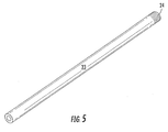
- the acetabular cup 14 is releasably engaged with the distal end of the orthopedic instrument 22 in the same manner as described above. Then the acetabular cup 14 is positioned in the acetabular socket of the pelvis and the impactor head 10 is impacted to set the acetabular cup 14 in place. Then the handle 20 is unscrewed from the acetabular impactor 21 and a sleeve 23 of Fig. 5 is inserted into one or both of channels 3 or 4. Sleeve 23 is also optionally provided with threads 24, preferably on a Morse taper, to mate with the threads in screw holes 25.
- the sleeve 23 is sized with suitable outer and inner diameters to prevent or minimize wobbling of the drill bit during drilling of the pelvic bone.
- the length of the sleeve 23 is sized to insure that the drill bit penetrates the bone to the appropriate depth without going too deep.
Landscapes
- Health & Medical Sciences (AREA)
- Orthopedic Medicine & Surgery (AREA)
- Life Sciences & Earth Sciences (AREA)
- Oral & Maxillofacial Surgery (AREA)
- General Health & Medical Sciences (AREA)
- Transplantation (AREA)
- Engineering & Computer Science (AREA)
- Biomedical Technology (AREA)
- Heart & Thoracic Surgery (AREA)
- Veterinary Medicine (AREA)
- Public Health (AREA)
- Animal Behavior & Ethology (AREA)
- Cardiology (AREA)
- Vascular Medicine (AREA)
- Surgery (AREA)
- Physical Education & Sports Medicine (AREA)
- Dentistry (AREA)
- Nuclear Medicine, Radiotherapy & Molecular Imaging (AREA)
- Medical Informatics (AREA)
- Molecular Biology (AREA)
- Prostheses (AREA)
Description
- The present invention has to do with an orthopedic instrument and its use in hip replacement surgery for implanting an acetabular cup in the pelvis of a patient. More specifically, the invention relates to a new orthopedic instrument designed for implanting the reverse hip acetabular cup described in Published
PCT Application No. WO 2011-112353-A1, dated September 15, 2011 , and entitled "Interlocking Reverse Hip and Revision Prosthesis" and its parent, PublishedU.S. Patent Application No. 2011-0218637-A1, dated September 8, 2011 . - The prior art discloses apparatus for implanting various portions of a prosthesis, such as an acetabular cup, into an anatomy. For example,
U.S. Patent No. 7,727,282 discloses an apparatus that rigidly engages a prosthesis member to allow for positioning it relative to the anatomy. Other documents disclose similar apparatus, like international patent applicationWO 2004/069107 ,DE102008022329 ,US5540697 ,FR2776182 US5431657 ,US 3916451 ,US 2005/085820 ,US 2005/203535 ,US5584837 andUS 2009/192621 . The apparatus disclosed in these documents do not allow engaging a reverse hip prosthesis to the anatomy satisfactorily. - The orthopedic instrument of the invention was developed to implant a revolutionary new reverse hip prosthesis in a patient. In particular, the instrument is used to position and securely affix the acetabular cup component of the prosthesis in the pelvis of a patient.
- Two methods of using the instrument are available to the surgeon. In one method, the acetabular cup is affixed to the pelvis without using screws and in the other method at least one screw is used. Drill guides can be incorporated in the instrument in case the surgeon wishes to use screws.
- The mechanical elements of the invention are illustrated in the drawings summarized as follows:
-
Fig. 1 is a semi-transparent elevational view of the orthopedic instrument. -
Fig. 2 is a top section view of the acetabular impactor taken along section line 2-2 ofFig. 1 . -
Fig. 3 illustrates a section view of the acetabular impactor with the acetabular cup releasably engaged thereto. -
Fig. 4 is a perspective view of the acetabular cup. -
Fig. 5 illustrates in perspective a sleeve used to guide the drill bit when a screw hole is drilled in the pelvic bone. - Referring to the drawings, the main components of the
orthopedic instrument 22 are ahandle 20 and anacetabular impactor 21. Thehandle 20 is comprised of ashaft 9, animpactor head 10 at the proximal end of theshaft 9 and a threaded portion at the distal end. The threaded portion of the handle is comprised of an axially disposed, internally threaded annular portion. Theacetabular impactor 21 is comprised ofthreads 8 at the proximal end for removably affixing theacetabular impactor 21 to thehandle 20 by screwing theacetabular impactor 21 and handle 20 together. Thethreads 8 are comprised of an axially disposed externally threaded portion. In a variation of the invention which is not illustrated in the drawings, the threads on the handle can be external and the threads on the acetabular impactor can be internal. - Other elements of the
acetabular impactor 21 include recess 1,hemispherical head 2, proximalconical extension 11, retainingtongues 5,release levers 6, hemi-circular retaining ring 7 and recesses 17. The retainingring 7 acts as a spring to allow the retainingtongues 5 to move laterally to removably engage theacetabular cup 14. Optional elements of the acetabular impactor include conical protective/supportive sheet 12 andchannels - The
acetabular cup 14 has astem 15 which is accommodated by recess 1 inacetabular impactor 21. Acircumferential groove 16 is located in the concave surface of the acetabular cup in proximity to the circumferential edge of the cup. As illustrated inFig. 3 , theretaining tongues 5 engage thecircumferential groove 16 when the acetabular cup is releasably engaged with theorthopedic instrument 22. In a variant of the invention,reference number 16 can designate diametrically opposed recesses for theretaining tongues 5.Surface 18 of the acetabular cup is adapted for secure attachment to the acetabular socket of a pelvis. In a preferred embodiment thesurface 18 is convex but other shapes suitable for secure attachment to a pelvic bone can be used as will be apparent to those skilled in the art. Referring toFig. 4 , thescrew holes 25 are optionally threaded and preferably are threaded in a portion of the holes having a Morse taper, the taper having a larger diameter on theconcave surface 19 of theacetabular cup 14 and a smaller diameter on theopposite side 18, said opposite side preferably having a convex shape. - An orthopedic system is provided according to the invention when the
acetabular cup 14 is removably engaged with theorthopedic instrument 22 or when theacetabular cup 14 is removably engaged with theacetabular impactor 21. - The apparatus according to the invention could be used according to at least two methods. The first method is employed when the surgeon does not use screws to affix the
acetabular cup 14 in the pelvis. The second method is employed when the surgeon uses at least one screw to affix theacetabular cup 14 to the pelvis. - In the first method, the
acetabular cup 14 is releasably engaged with the distal end of theorthopedic instrument 22 by snap fitting the cup over the retainingtongues 5 to engage thecircumferential groove 16. Then theacetabular cup 14 is positioned in the acetabular socket of the pelvis and theimpactor head 10 is impacted, such as with a hammer, to affix theacetabular cup 14 in the acetabular socket. Theorthopedic instrument 22 then is released from the acetabular cup by pressing release levers 6 inwardly. - In the second method, the
acetabular cup 14 is releasably engaged with the distal end of theorthopedic instrument 22 in the same manner as described above. Then theacetabular cup 14 is positioned in the acetabular socket of the pelvis and theimpactor head 10 is impacted to set theacetabular cup 14 in place. Then thehandle 20 is unscrewed from theacetabular impactor 21 and asleeve 23 ofFig. 5 is inserted into one or both ofchannels Sleeve 23 is also optionally provided withthreads 24, preferably on a Morse taper, to mate with the threads inscrew holes 25. When asleeve 23 is threaded into ascrew hole 25, the sleeve will not spin during drilling and the engagement of theacetabular cup 14 with theacetabular impactor 21 is enhanced. Thesleeve 23 is sized with suitable outer and inner diameters to prevent or minimize wobbling of the drill bit during drilling of the pelvic bone. The length of thesleeve 23 is sized to insure that the drill bit penetrates the bone to the appropriate depth without going too deep. After the hole is drilled, thesleeve 23 is removed, the screws are installed and theacetabular impactor 21 is released from theacetabular cup 14 as described above.
Claims (6)
- An orthopedic instrument (22) for implanting an acetabular cup (14) having a surface (18) for attachment to an acetabular socket in a pelvic bone and a concave surface (19) having an acetabular cup stem (15) affixed therein and projecting outwardly therefrom, the concave surface (19) further comprising a circumferential groove (16) located in proximity to a circumferential edge of the acetabular cup (14), the orthopedic instrument (22) comprising
a handle (20) comprising a shaft (9) having an impactor head (10) at a proximal end and an axially disposed first threaded annular portion at a distal end,
an acetabular impactor (21) having a hemispherical head (2) at a distal end and an axially disposed second threaded annular portion (8) at a proximal end, the second threaded annular portion (8) being screwed into the first threaded annular portion removably affixing the handle (20) to the acetabular impactor (21),
the hemispherical head (2) being configured to couple to the acetabular cup (14),
characterized in that the hemispherical head (2) comprises an annular recess (1) to receive the acetabular cup stem (15),
and in that the hemispherical head (2) furthermore comprises retaining tabs (5) configured to releasably engage the circumferential groove (16). - The orthopedic instrument (22) of claim 1, the acetabular cup (14) further comprising at least one screw hole (25) to accommodate a screw for attaching the acetabular cup (14) to the pelvic bone, the acetabular impactor (21) further comprising at least one channel (3, 4) configured as a drill guide.
- The orthopedic instrument (22) of claim 1 or 2 wherein the first threaded annular portion is internally threaded and the second threaded annular portion (8) is externally threaded.
- The orthopedic instrument (22) of claim 1 or 2, wherein the first threaded annular portion is externally threaded and the second threaded annular portion (8) is internally threaded.
- An orthopedic system for implanting an acetabular cup (14), the system comprising
the orthopedic instrument of any one of claims 1 to 4, and
an acetabular cup (14) having a surface (18) for attachment to an acetabular socket in a pelvic bone and a concave surface (19) having an acetabular cup stem (15) affixed therein and projecting outwardly therefrom, the concave surface (19) further comprising a circumferential groove (16) located in proximity to a circumferential edge of the acetabular cup (14). - The orthopedic system of claim 5, the acetabular cup (14) further comprising at least one screw hole (25) to accommodate a screw for attaching the acetabular cup (14) to the pelvic bone, the acetabular impactor (21) further comprising at least one channel (3,4) configured as a drill guide.
Applications Claiming Priority (2)
| Application Number | Priority Date | Filing Date | Title |
|---|---|---|---|
| US201161521030P | 2011-08-08 | 2011-08-08 | |
| PCT/US2012/047324 WO2013022586A1 (en) | 2011-08-08 | 2012-07-19 | Orthpedic instrument, system and method for implanting an acetabular cup |
Publications (3)
| Publication Number | Publication Date |
|---|---|
| EP2741715A1 EP2741715A1 (en) | 2014-06-18 |
| EP2741715A4 EP2741715A4 (en) | 2015-03-04 |
| EP2741715B1 true EP2741715B1 (en) | 2016-08-17 |
Family
ID=47668792
Family Applications (1)
| Application Number | Title | Priority Date | Filing Date |
|---|---|---|---|
| EP12821816.1A Active EP2741715B1 (en) | 2011-08-08 | 2012-07-19 | Orthopedic instrument and system for implanting an acetabular cup |
Country Status (10)
| Country | Link |
|---|---|
| US (1) | US9155632B2 (en) |
| EP (1) | EP2741715B1 (en) |
| JP (1) | JP6117204B2 (en) |
| KR (1) | KR101807351B1 (en) |
| CN (1) | CN103841922B (en) |
| AU (1) | AU2012294801B2 (en) |
| CA (1) | CA2838556C (en) |
| ES (1) | ES2592222T3 (en) |
| WO (1) | WO2013022586A1 (en) |
| ZA (1) | ZA201400152B (en) |
Families Citing this family (10)
| Publication number | Priority date | Publication date | Assignee | Title |
|---|---|---|---|---|
| CN103906482B (en) * | 2011-08-13 | 2015-12-09 | Hip创新科技有限责任公司 | Interlocking acetabular fixation screws and their combination with inverted acetabular cups |
| NZ770503A (en) * | 2015-07-27 | 2023-03-31 | Hip Innovation Technology Llc | Femoral cup impactor assembly and method and kit for femoral cup impactor |
| WO2017019328A1 (en) * | 2015-07-27 | 2017-02-02 | Hip Innovation Technology, LLC | Drill guide for acetabular cup fasteners |
| US10492929B2 (en) | 2016-08-02 | 2019-12-03 | Joint Innovation Technology, Llc | Tool and method for separating a femoral cup or a femoral ball from a femoral implant |
| US11185377B2 (en) | 2017-06-09 | 2021-11-30 | Mako Surgical Corp. | Systems and tools for positioning workpieces with surgical robots |
| JP6935959B2 (en) * | 2017-08-23 | 2021-09-15 | アイメディコム | Usu cup removal device for artificial hip joint |
| US11399963B2 (en) | 2020-05-15 | 2022-08-02 | Depuy Ireland Unlimited Company | Surgical instrument and method of positioning an acetabular prosthetic component |
| CN111494066A (en) * | 2020-06-09 | 2020-08-07 | 经纬医疗器材制造(深圳)有限公司 | Full acetabulum prosthesis outer cup implantation device with snap ring |
| US11090163B1 (en) * | 2021-01-09 | 2021-08-17 | Zafer Termanini | Interlocking reverse hip prosthesis with removable tapered central post |
| CN115300041B (en) * | 2022-08-10 | 2023-03-14 | 骨圣元化机器人(深圳)有限公司 | Acetabular osteotomy orthopedic surgery positioning tool, system and computer equipment |
Family Cites Families (18)
| Publication number | Priority date | Publication date | Assignee | Title |
|---|---|---|---|---|
| US3916451A (en) | 1974-10-25 | 1975-11-04 | Frederick F Buechel | Floating center prosthetic joint |
| US5540697A (en) | 1993-02-12 | 1996-07-30 | U.S. Medical Products, Inc. | Prosthetic socket installation apparatus and method |
| US5584837A (en) * | 1993-08-13 | 1996-12-17 | Petersen; Thomas D. | Acetabular cup inserter for orthopedic |
| US5431657A (en) | 1994-05-23 | 1995-07-11 | Zimmer, Inc. | Instrument for installing an acetabular cup assembly |
| GB9416215D0 (en) * | 1994-08-11 | 1994-10-05 | Howmedica | Acetabular bone graft impactor |
| FR2776182B1 (en) * | 1998-03-20 | 2001-07-13 | Groupe Lepine | ASSEMBLY OF ELEMENTS FOR THE PLACEMENT OF A COTYLOIDIAN IMPLANT |
| GB0302409D0 (en) * | 2003-02-03 | 2003-03-05 | Depuy Int Ltd | A cup component of an orthopaedics joint prosthesis |
| GB2406056B (en) | 2003-09-17 | 2007-07-11 | Corin Ltd | Prosthetic cup |
| US8070820B2 (en) | 2003-10-08 | 2011-12-06 | Biomet Manufacturing Corp. | Shoulder implant assembly |
| US7931656B2 (en) * | 2004-01-05 | 2011-04-26 | Paramount Medical Instruments, L.L.C. | Acetabular shell impactor |
| US9339278B2 (en) * | 2006-02-27 | 2016-05-17 | Biomet Manufacturing, Llc | Patient-specific acetabular guides and associated instruments |
| US7727282B2 (en) | 2006-03-17 | 2010-06-01 | Biomet Manufacturing Corp. | Method and apparatus for implanting a prosthesis |
| DE102008022329B4 (en) * | 2008-04-29 | 2014-05-15 | Aesculap Ag | Acetabulum and handling system for an acetabular cup |
| CN102046110B (en) * | 2008-05-27 | 2015-01-28 | 史密夫和内修有限公司 | Cup sheath to prevent soft tissue impact |
| DE102008049661A1 (en) * | 2008-09-30 | 2010-04-01 | Smith & Nephew Orthopaedics Ag | Instrument for handling a joint component |
| MX2012000518A (en) * | 2009-07-10 | 2012-06-28 | Milux Holding Sa | Hip joint device and method. |
| IT1399347B1 (en) * | 2009-07-17 | 2013-04-16 | Melozzi | NEW CONCEPTION PROSTHESIS. |
| US8313531B2 (en) | 2010-03-08 | 2012-11-20 | Hip Innovation Technology Llc | Interlocking reverse hip prosthesis and method |
-
2012
- 2012-07-19 WO PCT/US2012/047324 patent/WO2013022586A1/en not_active Ceased
- 2012-07-19 EP EP12821816.1A patent/EP2741715B1/en active Active
- 2012-07-19 CN CN201280038610.XA patent/CN103841922B/en active Active
- 2012-07-19 AU AU2012294801A patent/AU2012294801B2/en active Active
- 2012-07-19 JP JP2014525032A patent/JP6117204B2/en not_active Expired - Fee Related
- 2012-07-19 US US14/236,477 patent/US9155632B2/en active Active
- 2012-07-19 CA CA2838556A patent/CA2838556C/en active Active
- 2012-07-19 ES ES12821816.1T patent/ES2592222T3/en active Active
- 2012-07-19 KR KR1020147003204A patent/KR101807351B1/en active Active
-
2014
- 2014-01-08 ZA ZA2014/00152A patent/ZA201400152B/en unknown
Also Published As
| Publication number | Publication date |
|---|---|
| KR20140047117A (en) | 2014-04-21 |
| ES2592222T3 (en) | 2016-11-28 |
| EP2741715A4 (en) | 2015-03-04 |
| CN103841922A (en) | 2014-06-04 |
| CN103841922B (en) | 2016-02-03 |
| CA2838556C (en) | 2016-06-07 |
| JP2014531915A (en) | 2014-12-04 |
| US20150127113A1 (en) | 2015-05-07 |
| HK1194654A1 (en) | 2014-10-24 |
| ZA201400152B (en) | 2015-02-25 |
| AU2012294801B2 (en) | 2016-04-28 |
| KR101807351B1 (en) | 2017-12-08 |
| CA2838556A1 (en) | 2013-02-14 |
| US9155632B2 (en) | 2015-10-13 |
| EP2741715A1 (en) | 2014-06-18 |
| WO2013022586A1 (en) | 2013-02-14 |
| AU2012294801A1 (en) | 2014-01-09 |
| JP6117204B2 (en) | 2017-04-19 |
Similar Documents
| Publication | Publication Date | Title |
|---|---|---|
| CA2838556C (en) | Orthopedic instrument, system and method for implanting an acetabular cup | |
| CN110772360B (en) | Base plate for a modular shoulder prosthesis and associated method for implanting same | |
| JP5777882B2 (en) | Device for pre-processing bone for prosthetic devices | |
| EP2055273B1 (en) | Taper disengagement tool | |
| CN101273925B (en) | Assembly tool for modular implants, kit and associated method | |
| US8221432B2 (en) | Method and apparatus for implanting a modular femoral hip | |
| CA2803231C (en) | Insertion instrument for inserting socket inserts into hip sockets for hip endoprostheses | |
| EP2275045A1 (en) | Snap-lock for drill sleeve | |
| US20140228854A1 (en) | Apparatus And Method For Positioning A Prosthesis | |
| WO2018213054A1 (en) | Joint reaming devices | |
| US8333807B2 (en) | Method and apparatus for trialing and implanting a modular femoral hip | |
| CN112842614A (en) | Surgical tray, instruments and method for implanting a hip replacement prosthesis | |
| US20140081270A1 (en) | Bone graft shaper for reverse glenoid | |
| AU2020260529A1 (en) | Ball and cup impactors for implanting a hip prosthesis | |
| EP3328319B1 (en) | Drill guide for acetabular cup fasteners | |
| US20260083564A1 (en) | Glenoid implant components and instruments therefor | |
| JP6871746B2 (en) | Equipment guide assemblies for bone plates and kits of bone plates with such equipment guide assemblies | |
| EP3324861B1 (en) | Orthopedic instrumentation | |
| EP3934560B1 (en) | A dental drill guiding system | |
| HK1194654B (en) | Orthpedic instrument, system and method for implanting an acetabular cup | |
| WO2013046172A1 (en) | An orthopaedic apparatus | |
| HK40043057A (en) | Surgical trays, instruments and methods for implanting a hip replacement prosthesis |
Legal Events
| Date | Code | Title | Description |
|---|---|---|---|
| PUAI | Public reference made under article 153(3) epc to a published international application that has entered the european phase |
Free format text: ORIGINAL CODE: 0009012 |
|
| 17P | Request for examination filed |
Effective date: 20140204 |
|
| AK | Designated contracting states |
Kind code of ref document: A1 Designated state(s): AL AT BE BG CH CY CZ DE DK EE ES FI FR GB GR HR HU IE IS IT LI LT LU LV MC MK MT NL NO PL PT RO RS SE SI SK SM TR |
|
| DAX | Request for extension of the european patent (deleted) | ||
| A4 | Supplementary search report drawn up and despatched |
Effective date: 20150129 |
|
| RIC1 | Information provided on ipc code assigned before grant |
Ipc: A61F 2/34 20060101AFI20150123BHEP |
|
| 17Q | First examination report despatched |
Effective date: 20150210 |
|
| GRAP | Despatch of communication of intention to grant a patent |
Free format text: ORIGINAL CODE: EPIDOSNIGR1 |
|
| INTG | Intention to grant announced |
Effective date: 20160302 |
|
| GRAS | Grant fee paid |
Free format text: ORIGINAL CODE: EPIDOSNIGR3 |
|
| GRAA | (expected) grant |
Free format text: ORIGINAL CODE: 0009210 |
|
| AK | Designated contracting states |
Kind code of ref document: B1 Designated state(s): AL AT BE BG CH CY CZ DE DK EE ES FI FR GB GR HR HU IE IS IT LI LT LU LV MC MK MT NL NO PL PT RO RS SE SI SK SM TR |
|
| REG | Reference to a national code |
Ref country code: GB Ref legal event code: FG4D |
|
| REG | Reference to a national code |
Ref country code: CH Ref legal event code: EP |
|
| REG | Reference to a national code |
Ref country code: IE Ref legal event code: FG4D |
|
| REG | Reference to a national code |
Ref country code: AT Ref legal event code: REF Ref document number: 820323 Country of ref document: AT Kind code of ref document: T Effective date: 20160915 |
|
| REG | Reference to a national code |
Ref country code: NL Ref legal event code: FP |
|
| REG | Reference to a national code |
Ref country code: SE Ref legal event code: TRGR |
|
| REG | Reference to a national code |
Ref country code: DE Ref legal event code: R096 Ref document number: 602012022011 Country of ref document: DE |
|
| REG | Reference to a national code |
Ref country code: ES Ref legal event code: FG2A Ref document number: 2592222 Country of ref document: ES Kind code of ref document: T3 Effective date: 20161128 |
|
| REG | Reference to a national code |
Ref country code: LT Ref legal event code: MG4D |
|
| PG25 | Lapsed in a contracting state [announced via postgrant information from national office to epo] |
Ref country code: RS Free format text: LAPSE BECAUSE OF FAILURE TO SUBMIT A TRANSLATION OF THE DESCRIPTION OR TO PAY THE FEE WITHIN THE PRESCRIBED TIME-LIMIT Effective date: 20160817 Ref country code: NO Free format text: LAPSE BECAUSE OF FAILURE TO SUBMIT A TRANSLATION OF THE DESCRIPTION OR TO PAY THE FEE WITHIN THE PRESCRIBED TIME-LIMIT Effective date: 20161117 Ref country code: HR Free format text: LAPSE BECAUSE OF FAILURE TO SUBMIT A TRANSLATION OF THE DESCRIPTION OR TO PAY THE FEE WITHIN THE PRESCRIBED TIME-LIMIT Effective date: 20160817 Ref country code: FI Free format text: LAPSE BECAUSE OF FAILURE TO SUBMIT A TRANSLATION OF THE DESCRIPTION OR TO PAY THE FEE WITHIN THE PRESCRIBED TIME-LIMIT Effective date: 20160817 Ref country code: LT Free format text: LAPSE BECAUSE OF FAILURE TO SUBMIT A TRANSLATION OF THE DESCRIPTION OR TO PAY THE FEE WITHIN THE PRESCRIBED TIME-LIMIT Effective date: 20160817 |
|
| PG25 | Lapsed in a contracting state [announced via postgrant information from national office to epo] |
Ref country code: GR Free format text: LAPSE BECAUSE OF FAILURE TO SUBMIT A TRANSLATION OF THE DESCRIPTION OR TO PAY THE FEE WITHIN THE PRESCRIBED TIME-LIMIT Effective date: 20161118 Ref country code: PT Free format text: LAPSE BECAUSE OF FAILURE TO SUBMIT A TRANSLATION OF THE DESCRIPTION OR TO PAY THE FEE WITHIN THE PRESCRIBED TIME-LIMIT Effective date: 20161219 Ref country code: LV Free format text: LAPSE BECAUSE OF FAILURE TO SUBMIT A TRANSLATION OF THE DESCRIPTION OR TO PAY THE FEE WITHIN THE PRESCRIBED TIME-LIMIT Effective date: 20160817 Ref country code: PL Free format text: LAPSE BECAUSE OF FAILURE TO SUBMIT A TRANSLATION OF THE DESCRIPTION OR TO PAY THE FEE WITHIN THE PRESCRIBED TIME-LIMIT Effective date: 20160817 |
|
| PG25 | Lapsed in a contracting state [announced via postgrant information from national office to epo] |
Ref country code: EE Free format text: LAPSE BECAUSE OF FAILURE TO SUBMIT A TRANSLATION OF THE DESCRIPTION OR TO PAY THE FEE WITHIN THE PRESCRIBED TIME-LIMIT Effective date: 20160817 Ref country code: RO Free format text: LAPSE BECAUSE OF FAILURE TO SUBMIT A TRANSLATION OF THE DESCRIPTION OR TO PAY THE FEE WITHIN THE PRESCRIBED TIME-LIMIT Effective date: 20160817 |
|
| REG | Reference to a national code |
Ref country code: DE Ref legal event code: R097 Ref document number: 602012022011 Country of ref document: DE |
|
| PG25 | Lapsed in a contracting state [announced via postgrant information from national office to epo] |
Ref country code: SM Free format text: LAPSE BECAUSE OF FAILURE TO SUBMIT A TRANSLATION OF THE DESCRIPTION OR TO PAY THE FEE WITHIN THE PRESCRIBED TIME-LIMIT Effective date: 20160817 Ref country code: DK Free format text: LAPSE BECAUSE OF FAILURE TO SUBMIT A TRANSLATION OF THE DESCRIPTION OR TO PAY THE FEE WITHIN THE PRESCRIBED TIME-LIMIT Effective date: 20160817 Ref country code: CZ Free format text: LAPSE BECAUSE OF FAILURE TO SUBMIT A TRANSLATION OF THE DESCRIPTION OR TO PAY THE FEE WITHIN THE PRESCRIBED TIME-LIMIT Effective date: 20160817 Ref country code: SK Free format text: LAPSE BECAUSE OF FAILURE TO SUBMIT A TRANSLATION OF THE DESCRIPTION OR TO PAY THE FEE WITHIN THE PRESCRIBED TIME-LIMIT Effective date: 20160817 Ref country code: BG Free format text: LAPSE BECAUSE OF FAILURE TO SUBMIT A TRANSLATION OF THE DESCRIPTION OR TO PAY THE FEE WITHIN THE PRESCRIBED TIME-LIMIT Effective date: 20161117 |
|
| REG | Reference to a national code |
Ref country code: FR Ref legal event code: PLFP Year of fee payment: 6 |
|
| PLBE | No opposition filed within time limit |
Free format text: ORIGINAL CODE: 0009261 |
|
| STAA | Information on the status of an ep patent application or granted ep patent |
Free format text: STATUS: NO OPPOSITION FILED WITHIN TIME LIMIT |
|
| 26N | No opposition filed |
Effective date: 20170518 |
|
| PG25 | Lapsed in a contracting state [announced via postgrant information from national office to epo] |
Ref country code: SI Free format text: LAPSE BECAUSE OF FAILURE TO SUBMIT A TRANSLATION OF THE DESCRIPTION OR TO PAY THE FEE WITHIN THE PRESCRIBED TIME-LIMIT Effective date: 20160817 |
|
| REG | Reference to a national code |
Ref country code: FR Ref legal event code: PLFP Year of fee payment: 7 |
|
| PG25 | Lapsed in a contracting state [announced via postgrant information from national office to epo] |
Ref country code: MT Free format text: LAPSE BECAUSE OF NON-PAYMENT OF DUE FEES Effective date: 20170719 |
|
| PG25 | Lapsed in a contracting state [announced via postgrant information from national office to epo] |
Ref country code: AL Free format text: LAPSE BECAUSE OF FAILURE TO SUBMIT A TRANSLATION OF THE DESCRIPTION OR TO PAY THE FEE WITHIN THE PRESCRIBED TIME-LIMIT Effective date: 20160817 |
|
| REG | Reference to a national code |
Ref country code: AT Ref legal event code: UEP Ref document number: 820323 Country of ref document: AT Kind code of ref document: T Effective date: 20160817 |
|
| PG25 | Lapsed in a contracting state [announced via postgrant information from national office to epo] |
Ref country code: HU Free format text: LAPSE BECAUSE OF FAILURE TO SUBMIT A TRANSLATION OF THE DESCRIPTION OR TO PAY THE FEE WITHIN THE PRESCRIBED TIME-LIMIT; INVALID AB INITIO Effective date: 20120719 Ref country code: MC Free format text: LAPSE BECAUSE OF FAILURE TO SUBMIT A TRANSLATION OF THE DESCRIPTION OR TO PAY THE FEE WITHIN THE PRESCRIBED TIME-LIMIT Effective date: 20160817 |
|
| PG25 | Lapsed in a contracting state [announced via postgrant information from national office to epo] |
Ref country code: CY Free format text: LAPSE BECAUSE OF NON-PAYMENT OF DUE FEES Effective date: 20160817 |
|
| PG25 | Lapsed in a contracting state [announced via postgrant information from national office to epo] |
Ref country code: MK Free format text: LAPSE BECAUSE OF FAILURE TO SUBMIT A TRANSLATION OF THE DESCRIPTION OR TO PAY THE FEE WITHIN THE PRESCRIBED TIME-LIMIT Effective date: 20160817 |
|
| PG25 | Lapsed in a contracting state [announced via postgrant information from national office to epo] |
Ref country code: IS Free format text: LAPSE BECAUSE OF FAILURE TO SUBMIT A TRANSLATION OF THE DESCRIPTION OR TO PAY THE FEE WITHIN THE PRESCRIBED TIME-LIMIT Effective date: 20161217 |
|
| P01 | Opt-out of the competence of the unified patent court (upc) registered |
Effective date: 20230530 |
|
| PGFP | Annual fee paid to national office [announced via postgrant information from national office to epo] |
Ref country code: GB Payment date: 20251212 Year of fee payment: 14 |
|
| PGFP | Annual fee paid to national office [announced via postgrant information from national office to epo] |
Ref country code: TR Payment date: 20251231 Year of fee payment: 14 |
|
| REG | Reference to a national code |
Ref country code: CH Ref legal event code: U11 Free format text: ST27 STATUS EVENT CODE: U-0-0-U10-U11 (AS PROVIDED BY THE NATIONAL OFFICE) Effective date: 20260119 |
|
| PGFP | Annual fee paid to national office [announced via postgrant information from national office to epo] |
Ref country code: NL Payment date: 20260121 Year of fee payment: 14 Ref country code: LU Payment date: 20260121 Year of fee payment: 14 |
|
| PGFP | Annual fee paid to national office [announced via postgrant information from national office to epo] |
Ref country code: SE Payment date: 20260121 Year of fee payment: 14 |
|
| PGFP | Annual fee paid to national office [announced via postgrant information from national office to epo] |
Ref country code: ES Payment date: 20260130 Year of fee payment: 14 |
|
| PGFP | Annual fee paid to national office [announced via postgrant information from national office to epo] |
Ref country code: IE Payment date: 20260120 Year of fee payment: 14 Ref country code: DE Payment date: 20260119 Year of fee payment: 14 |
|
| PGFP | Annual fee paid to national office [announced via postgrant information from national office to epo] |
Ref country code: AT Payment date: 20260121 Year of fee payment: 14 |
|
| PGFP | Annual fee paid to national office [announced via postgrant information from national office to epo] |
Ref country code: BE Payment date: 20260121 Year of fee payment: 14 Ref country code: IT Payment date: 20260126 Year of fee payment: 14 |
|
| PGFP | Annual fee paid to national office [announced via postgrant information from national office to epo] |
Ref country code: FR Payment date: 20260120 Year of fee payment: 14 |
|
| PGFP | Annual fee paid to national office [announced via postgrant information from national office to epo] |
Ref country code: CH Payment date: 20260119 Year of fee payment: 14 |