EP2741399A1 - Motor rotor and motor having same - Google Patents
Motor rotor and motor having same Download PDFInfo
- Publication number
- EP2741399A1 EP2741399A1 EP11870544.1A EP11870544A EP2741399A1 EP 2741399 A1 EP2741399 A1 EP 2741399A1 EP 11870544 A EP11870544 A EP 11870544A EP 2741399 A1 EP2741399 A1 EP 2741399A1
- Authority
- EP
- European Patent Office
- Prior art keywords
- iron core
- motor
- rotor
- mounting slots
- reinforcing
- Prior art date
- Legal status (The legal status is an assumption and is not a legal conclusion. Google has not performed a legal analysis and makes no representation as to the accuracy of the status listed.)
- Granted
Links
Images


Classifications
-
- H—ELECTRICITY
- H02—GENERATION; CONVERSION OR DISTRIBUTION OF ELECTRIC POWER
- H02K—DYNAMO-ELECTRIC MACHINES
- H02K1/00—Details of the magnetic circuit
- H02K1/06—Details of the magnetic circuit characterised by the shape, form or construction
- H02K1/22—Rotating parts of the magnetic circuit
- H02K1/27—Rotor cores with permanent magnets
-
- H—ELECTRICITY
- H02—GENERATION; CONVERSION OR DISTRIBUTION OF ELECTRIC POWER
- H02K—DYNAMO-ELECTRIC MACHINES
- H02K1/00—Details of the magnetic circuit
- H02K1/06—Details of the magnetic circuit characterised by the shape, form or construction
- H02K1/22—Rotating parts of the magnetic circuit
- H02K1/24—Rotor cores with salient poles ; Variable reluctance rotors
- H02K1/246—Variable reluctance rotors
-
- H—ELECTRICITY
- H02—GENERATION; CONVERSION OR DISTRIBUTION OF ELECTRIC POWER
- H02K—DYNAMO-ELECTRIC MACHINES
- H02K1/00—Details of the magnetic circuit
- H02K1/06—Details of the magnetic circuit characterised by the shape, form or construction
- H02K1/22—Rotating parts of the magnetic circuit
- H02K1/27—Rotor cores with permanent magnets
- H02K1/2706—Inner rotors
- H02K1/272—Inner rotors the magnetisation axis of the magnets being perpendicular to the rotor axis
- H02K1/274—Inner rotors the magnetisation axis of the magnets being perpendicular to the rotor axis the rotor consisting of two or more circumferentially positioned magnets
- H02K1/2753—Inner rotors the magnetisation axis of the magnets being perpendicular to the rotor axis the rotor consisting of two or more circumferentially positioned magnets the rotor consisting of magnets or groups of magnets arranged with alternating polarity
- H02K1/276—Magnets embedded in the magnetic core, e.g. interior permanent magnets [IPM]
- H02K1/2766—Magnets embedded in the magnetic core, e.g. interior permanent magnets [IPM] having a flux concentration effect
-
- H—ELECTRICITY
- H02—GENERATION; CONVERSION OR DISTRIBUTION OF ELECTRIC POWER
- H02K—DYNAMO-ELECTRIC MACHINES
- H02K2213/00—Specific aspects, not otherwise provided for and not covered by codes H02K2201/00 - H02K2211/00
- H02K2213/03—Machines characterised by numerical values, ranges, mathematical expressions or similar information
Definitions
- the present disclosure relates to the field of electric motor, and more specially, to a motor rotor and a motor having same.
- the permanent magnet assisted synchronous reluctance motor combines the merit of the permanent magnet motor and that of the synchronous reluctance motor, and it has the advantages of high power density, wide range of speed regulation, high efficiency, small volume and so on.
- T is the output torque of the motor, and the performance of the motor can be improved by increasing the value of T;
- the first term, after T in the equation, is the reluctance torque;
- the second term is the permanent magnetic torque;
- ⁇ PM is the maximum of the stator and rotor coupling flux generated by the permanent magnet of the motor;
- m is the number of the phases of the stator winding;
- L d and L q are respectively the d-axis inductance and the q-axis inductance, wherein d-axis refers to the axis that is coincide with the main magnetic pole axis;
- q-axis refers to the axis that is perpendicular to the main magnetic pole axis, wherein "perpendicular to" involves the electric angle;
- i d and i q respectively represent the armature current component along the d-axis and the armature current component along the q-axis.
- the performance of the motor is improved mainly by improving the performance of the permanent magnet, i.e. the value of the composite torque is increased by increasing the permanent magnetic torque, so as to improve the efficiency of the motor.
- a common method is to embed rare earth permanent magnets in the motor. As rare earth belongs to non-renewable resources and is expensive, the wider application of this kind of motor is limited.
- the pressing demand of further improving the efficiency of the motor cannot be satisfied only through improving the performance of the motor by means of improving the performance of the permanent magnet. What's more, if the permanent magnet is inserted into the motor, the edge of the rotor will be stretched and deformed or even ruptured when the rotor rotates at a high speed.
- the present invention aims at providing a motor rotor and a motor having same.
- the present invention provides a motor rotor comprising an iron core and a plurality of sets of permanent magnets provided therein, wherein: a plurality of sets of mounting slots are circumferentially distributed in the iron core; each set of mounting slots comprises two or more layers of mounting slots provided at intervals in radial direction of the iron core; the permanent magnets of each set of permanent magnets are correspondingly embedded into the mounting slots of each set of mounting slots; an island-shaped region is formed between each outermost layer of mounting slot and the periphery of the iron core, and a reinforcing hole is provided in at least one of the island-shaped regions; a reinforcing rod is provided in each reinforcing hole; and at each end of the iron core, ends of all reinforcing rods are connected with a reinforcing member.
- the reinforcing hole is a through hole provided in the rotor; the reinforcing rod is a rivet; and each of the rivets goes through the corresponding through hole and is connected with the reinforcing members at both ends.
- each island-shaped region corresponding to each set of mounting slots is provided with said reinforcing hole.
- the reinforcing members are two fixing baffles, each of which is provided at a corresponding end of the iron core; the reinforcing rod goes through the reinforcing hole and is connected with the fixing baffles at both ends.
- values of distance L between ends of each layer of mounting slot of each set and the periphery of the iron core increase gradually.
- each set of mounting slots comprises two layers of mounting slots
- formula 2L a ⁇ L b ⁇ 1.1 L a is satisfied, wherein, L a is a distance from an edge of the outmost layer of mounting slot to the periphery of the iron core, and L b is a distance from an edge of an adjacent layer of mounting slot to the periphery of the iron core.
- each set of mounting slots comprises three or more layers of mounting slots provided at intervals in redial direction of the iron core.
- formulae 2L b ⁇ L c ⁇ 1.2L b and 2L a ⁇ L b ⁇ 1.1 L a are satisfied, wherein, L a , L b and L c are respectively the distance between the periphery of the iron core and ends of three mounting slots, which is in an order from the outmost layer of mounting slot to the center of the iron core.
- a motor comprises a motor stator and the motor rotor above; the motor rotor is disposed at an inner side of the motor stator.
- the motor further comprising two fixing baffles; the rivets go through the fixing baffles and the iron core, and connect the fixing baffles to the rotor.
- a spacing n between an inner perimeter of the motor stator 50 and an outer periphery of the motor rotor is within the range of 0.35 mm ⁇ n ⁇ 0.55 mm.
- an island-shaped region is formed between each outermost layer of mounting slot and the periphery of the iron core; a reinforcing hole is provided in the island-shaped region; and a reinforcing rod is provided in each reinforcing hole.
- the structural strength of the rotor is enhanced.
- the present invention reinforces the structure of the rotor greatly, reduces the deformation extent of the rotor when it rotates at a high speed, thereby achieving the minimization of the clearance between the stator and the rotor, and enhancing the performance of the motor.
- the motor rotor comprises an iron core 10 and permanent magnets 20 provided therein.
- a plurality of sets of mounting slots 30 are circumferentially distributed in the iron core 10.
- Each set of mounting slots 30 comprises two or more layers of mounting slots 30 provided at intervals in radial direction of the iron core 10.
- An island-shaped region 12 is formed between each of the outermost layers of mounting slots 30 and the periphery of the iron core 10, and a reinforcing hole 13 is provided in the island-shaped region 12.
- a reinforcing rod 60 is provided in each reinforcing hole 13, and at each end of the iron core, ends of all reinforcing rods 60 are connected with a reinforcing member.
- the island-shaped regions 12 are formed between the outermost layers of mounting slots 30 and the periphery of the iron core 10.
- the motor rotor has the largest deformation at the island-shaped regions.
- the reinforcing hole 13 is provided in the island-shaped region 12 and along the symmetry axis of the set of the mounting slots on the rotor.
- the reinforcing rod 60 is provided in the reinforcing hole 13, and at each end of the iron core, ends of all reinforcing rods 60 are connected with the reinforcing member so as to reinforce the structure of the rotor.
- a reinforcing hole 13 is provided in each island-shaped region 12, so as to further reinforce the structure of the rotor. Consequently, without changing the magnetic flux path of the rotor, just by means of disposing reinforcing holes 13 and reinforcing rods 60 in the rotor, the structure of the rotor is reinforced significantly and the deformation of the rotor is reduced when the rotor rotates at a high speed, thereby realizing the minimization of the clearance between the stator and the rotor, and enhancing the performance of the motor.
- the reinforcing members are two fixing baffles 70, each of which is provided at a corresponding end of the iron core 10. The reinforcing rod 60 goes through the reinforcing hole 13 and is connected with the fixing baffles 70 at both ends.
- the reinforcing holes 13 are through holes provided in the rotor, and the reinforcing rods 60 are rivets. Each of the rivets goes through the corresponding through hole and is connected with the reinforcing members at both ends.
- the reinforcing hole 13 passing through the rotor is provided along the symmetry axis of the set of mounting slots 30 of the rotor.
- the rivet goes through the reinforcing hole 13 and is riveted with the reinforcing members at both ends.
- both ends of the iron core 10 of the rotor are respectively provided with a corresponding fixing baffle 70.
- the fixing baffles 70 and the rotor are riveted together integrally by the rivets going through the fixing baffles 70 at two ends of the iron core and going through the island-shaped regions 12 on the rotor.
- the deformation of the island-shaped regions is more strictly limited due to the restriction of the rivets. Consequently, the mechanical strength of the rotor is reinforced.
- the reinforcing rod 60 is a screw bolt and is connected with the reinforcing hole 13 by means of screw-thread connection.
- a rotor shaft hole 11 is provided in the center of the iron core of the rotor.
- Fig. 2 shows a stress nephogram when the motor rotor rotates at a high speed.
- the flux barrier bridge 40c endures much larger stress than the flux barrier bridges 40a and 40b, so the flux barrier bridge 40c is most prone to deform and rupture.
- the deformation extent of the edge of the rotor relies on the width of the flux barrier bridge 40 disposed at the periphery of the rotor.
- the motor can operate at a higher rotating speed.
- the negative effect is that the magnetic leakage at the ends of each set of permanent magnets 20 will be increased, which will reduce the effective magnetic flux in the stator and the rotor, and lead to degradation of the performance of the motor.
- the present invention provides an optimization design of the flux barrier bridges formed between ends of the mounting slots 30 and the periphery of the rotor, and more especially, based on the multilayer structure of each set of permanent magnets 20, provides different designs for the width of the flux barrier bridges for different layers, so as to achieve gradient width for the flux barrier bridges.
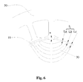
- Fig.6 from the periphery of the iron core 10 toward the axis of rotation, values of distance L between ends of each layer of mounting slot 30 of each set and the periphery of the iron core 10 increase gradually.
- each set of mounting slots 30 comprises two layers of mounting slots
- the formula 2L a ⁇ L b ⁇ 1.1L a is satisfied, wherein, L a is the distance between the end of the outmost layer of mounting slot 30 and the periphery of the iron core 10, and L b is the distance between the end of the adjacent layer of mounting slot 30 and the periphery of the iron core 10.
- each set of mounting slots comprises three or more layers of mounting slots provided at intervals in redial direction of the iron core 10
- the formulae 2L b ⁇ L c ⁇ 1.2L b and 2L a ⁇ L b ⁇ 1.1L a are satisfied, wherein, L a , L b and L c are respectively the distance between the periphery of the iron core 10 and the ends of the three mounting slots 30 in an order from the outmost layer of mounting slot 30 to the center of the iron core.
- Fig. 5 is a diagram illustrating the deformation of the motor rotor when it rotates at a high speed.
- the broken line represents the structure of the rotor when the rotor is still and the real line represents the structure of the rotor after the rotor deforms.
- the island-shaped region at the outmost layer of magnetic steel slot has the largest deformation, that is, the rotor deforms along the symmetry axis of the mounting slots 30.
- the deformation can be controlled under 20 ⁇ m and the stress of the flux barrier bridges 40c also can be controlled within the safe range.
- each set of mounting slots 30 is provided with three or more layers of mounting slots at intervals along the radial direction of the iron core 10
- the distances between the ends of the mounting slots 30 and the periphery of the iron core 10 also satisfy the formula 2L a ⁇ L b ⁇ 1.1L a above, wherein Lb is the distance between the end of the mounting slot 30 (which is the closest to the center of the circle) and the periphery of the iron core 10, La is the distance between the second closest mounting slot to the center of the circle and the periphery of the iron core 10.
- the limitation of the two ranges can be implemented separately or jointly, either way of implementation can improve the mechanical strength of the rotor and reduce the deformation extent of the rotor when it rotates at a high speed.
- the present disclosure further provides a motor comprising a motor stator 50 and the motor rotor described above.
- the motor rotor is disposed at the inner side of the motor stator 50.
- the motor further comprises fixing baffles 70. Rivets go through the fixing baffles 70 and the iron core 10 and connect the fixing baffles 70 to the rotor.
- the spacing n between the inner perimeter of the motor stator 50 and the outer periphery of the motor rotor is within the range of 0.35mm ⁇ n ⁇ 0.55mm.
- the deformation extent of the edge of the rotor relies on the width of the flux barrier bridges disposed at the periphery of the rotor.
- the motor can operate at a higher rotating speed.
- the negative effect is that the magnetic leakage at the ends of each set of permanent magnets 20 will be increased, which will reduce the efficiency of the motor.
- the present invention provides the optimization design of the flux barrier bridges formed between ends of the magnet steel slots and the periphery of the rotor, and more especially, based on the multilayer structure of each set of permanent magnets, provides a design of gradient width for the flux barrier bridges, which improves the mechanical strength of the rotor, and reduces the deformation extent of the rotor when it rotates at a high speed.
- the reinforcing holes are provided in the island-shaped regions 12 at the outmost layer of the mounting slots 30, and two ends of the iron core 10 of the rotor are provided with fixing baffles 70. Bolts or rivets go through the fixing baffles 70 at two ends of the iron core and the island-shaped regions 12 to fix the iron core 10 and the fixing baffles 70 together integrally.
- the present invention reinforces the structure of the rotor greatly, reduces the deformation extent of the rotor when it rotates at a high speed, thereby realizing the minimization of the clearance between the stator and the rotor, and enhancing the performance of the motor.
- the spacing n between the rotor with multilayer structure of embedded permanent magnets and the stator 50 can be designed smaller, thereby the loss of the magnetic flux will be less and the performance of the motor will be improved. According to practical tests, when n satisfies the formula 0.35mm ⁇ n ⁇ 0.55mm, the performance of the motor and the deformation extent of the rotor can meet the requirements of reliability.
Landscapes
- Engineering & Computer Science (AREA)
- Power Engineering (AREA)
- Permanent Field Magnets Of Synchronous Machinery (AREA)
- Iron Core Of Rotating Electric Machines (AREA)
Abstract
Description
- The present disclosure relates to the field of electric motor, and more specially, to a motor rotor and a motor having same.
- As a new permanent magnet motor, the permanent magnet assisted synchronous reluctance motor combines the merit of the permanent magnet motor and that of the synchronous reluctance motor, and it has the advantages of high power density, wide range of speed regulation, high efficiency, small volume and so on. The permanent magnet assisted synchronous reluctance motor has prominent application prospect in the field of drive and speed regulation, and the formula for its magnetic torque is illustrated as follows:

- Wherein, T is the output torque of the motor, and the performance of the motor can be improved by increasing the value of T; the first term, after T in the equation, is the reluctance torque; the second term is the permanent magnetic torque; Ψ PM is the maximum of the stator and rotor coupling flux generated by the permanent magnet of the motor; m is the number of the phases of the stator winding; Ld and Lq are respectively the d-axis inductance and the q-axis inductance, wherein d-axis refers to the axis that is coincide with the main magnetic pole axis; q-axis refers to the axis that is perpendicular to the main magnetic pole axis, wherein "perpendicular to" involves the electric angle; id and iq respectively represent the armature current component along the d-axis and the armature current component along the q-axis.
- In the prior art, the performance of the motor is improved mainly by improving the performance of the permanent magnet, i.e. the value of the composite torque is increased by increasing the permanent magnetic torque, so as to improve the efficiency of the motor. A common method is to embed rare earth permanent magnets in the motor. As rare earth belongs to non-renewable resources and is expensive, the wider application of this kind of motor is limited. Moreover, the pressing demand of further improving the efficiency of the motor cannot be satisfied only through improving the performance of the motor by means of improving the performance of the permanent magnet. What's more, if the permanent magnet is inserted into the motor, the edge of the rotor will be stretched and deformed or even ruptured when the rotor rotates at a high speed.
- The present invention aims at providing a motor rotor and a motor having same.
- The present invention provides a motor rotor comprising an iron core and a plurality of sets of permanent magnets provided therein, wherein: a plurality of sets of mounting slots are circumferentially distributed in the iron core; each set of mounting slots comprises two or more layers of mounting slots provided at intervals in radial direction of the iron core; the permanent magnets of each set of permanent magnets are correspondingly embedded into the mounting slots of each set of mounting slots; an island-shaped region is formed between each outermost layer of mounting slot and the periphery of the iron core, and a reinforcing hole is provided in at least one of the island-shaped regions; a reinforcing rod is provided in each reinforcing hole; and at each end of the iron core, ends of all reinforcing rods are connected with a reinforcing member.
- Preferably, the reinforcing hole is a through hole provided in the rotor; the reinforcing rod is a rivet; and each of the rivets goes through the corresponding through hole and is connected with the reinforcing members at both ends.
- Preferably, each island-shaped region corresponding to each set of mounting slots is provided with said reinforcing hole.
- Preferably, the reinforcing members are two fixing baffles, each of which is provided at a corresponding end of the iron core; the reinforcing rod goes through the reinforcing hole and is connected with the fixing baffles at both ends.
- Preferably, from the periphery of the iron core toward the axis of rotation, values of distance L between ends of each layer of mounting slot of each set and the periphery of the iron core increase gradually.
- Preferably, when each set of mounting slots comprises two layers of mounting slots, formula 2La ≥ Lb ≥ 1.1 La is satisfied, wherein, La is a distance from an edge of the outmost layer of mounting slot to the periphery of the iron core, and Lb is a distance from an edge of an adjacent layer of mounting slot to the periphery of the iron core.
- Preferably, each set of mounting slots comprises three or more layers of mounting slots provided at intervals in redial direction of the iron core.
- Preferably, formulae 2Lb ≥ Lc ≥ 1.2Lb and 2La ≥ Lb ≥ 1.1 La are satisfied, wherein, La, Lb and Lc are respectively the distance between the periphery of the iron core and ends of three mounting slots, which is in an order from the outmost layer of mounting slot to the center of the iron core.
- A motor comprises a motor stator and the motor rotor above; the motor rotor is disposed at an inner side of the motor stator.
- Preferably, the motor further comprising two fixing baffles; the rivets go through the fixing baffles and the iron core, and connect the fixing baffles to the rotor.
- Preferably, a spacing n between an inner perimeter of the
motor stator 50 and an outer periphery of the motor rotor is within the range of 0.35 mm ≤ n ≤ 0.55 mm. - According to the motor rotor and the motor having same of the present invention, an island-shaped region is formed between each outermost layer of mounting slot and the periphery of the iron core; a reinforcing hole is provided in the island-shaped region; and a reinforcing rod is provided in each reinforcing hole. Thus the structural strength of the rotor is enhanced. Without changing the magnetic flux path of the rotor, by disposing reinforcing holes and reinforcing rods, the present invention reinforces the structure of the rotor greatly, reduces the deformation extent of the rotor when it rotates at a high speed, thereby achieving the minimization of the clearance between the stator and the rotor, and enhancing the performance of the motor.
- The drawings of the present application are provided for further comprehension of the present disclosure. The illustrative embodiments of the present invention and the corresponding description aim at explaining the present disclosure but are not intended to restrict the present disclosure. Regarding the drawings:
-
Fig. 1 is a structural diagram illustrating the motor rotor according to the present disclosure; -
Fig. 2 is a profile illustrating the stress distribution when the motor rotor rotates at a high speed according to the present disclosure; -
Fig. 3 is a partial structural diagram illustrating the motor rotor according to the present disclosure; -
Fig. 4 is a structural diagram illustrating the reinforcing structure of the motor rotor according to the present disclosure; -
Fig. 5 is a schematic diagram illustrating the deformation of the motor rotor when it rotates at a high speed according to the present disclosure; -
Fig.6 is a structural diagram illustrating the stator and the rotor of the motor according to the present disclosure. - The embodiments of the present invention will be described in details with reference to the accompanying drawings.
- The motor rotor according to the present disclosure comprises an
iron core 10 andpermanent magnets 20 provided therein. A plurality of sets ofmounting slots 30 are circumferentially distributed in theiron core 10. Each set ofmounting slots 30 comprises two or more layers ofmounting slots 30 provided at intervals in radial direction of theiron core 10. There are a plurality of sets ofpermanent magnets 20, and thepermanent magnets 20 of each set ofpermanent magnets 20 are correspondingly embedded into themounting slots 30 of each set ofmounting slots 30. An island-shaped region 12 is formed between each of the outermost layers ofmounting slots 30 and the periphery of theiron core 10, and areinforcing hole 13 is provided in the island-shaped region 12. A reinforcingrod 60 is provided in each reinforcinghole 13, and at each end of the iron core, ends of all reinforcingrods 60 are connected with a reinforcing member. - As shown in
Figs. 1 and3 , the island-shaped regions 12 are formed between the outermost layers ofmounting slots 30 and the periphery of theiron core 10. As shown inFig.5 , the motor rotor has the largest deformation at the island-shaped regions. As shown inFigs.3 and4 , thereinforcing hole 13 is provided in the island-shaped region 12 and along the symmetry axis of the set of the mounting slots on the rotor. The reinforcingrod 60 is provided in the reinforcinghole 13, and at each end of the iron core, ends of all reinforcingrods 60 are connected with the reinforcing member so as to reinforce the structure of the rotor. Preferably, a reinforcinghole 13 is provided in each island-shaped region 12, so as to further reinforce the structure of the rotor. Consequently, without changing the magnetic flux path of the rotor, just by means of disposing reinforcingholes 13 and reinforcingrods 60 in the rotor, the structure of the rotor is reinforced significantly and the deformation of the rotor is reduced when the rotor rotates at a high speed, thereby realizing the minimization of the clearance between the stator and the rotor, and enhancing the performance of the motor. Preferably, the reinforcing members are twofixing baffles 70, each of which is provided at a corresponding end of theiron core 10. The reinforcingrod 60 goes through thereinforcing hole 13 and is connected with thefixing baffles 70 at both ends. - In order to further reinforce the mechanical strength of the rotor, the reinforcing
holes 13 are through holes provided in the rotor, and the reinforcingrods 60 are rivets. Each of the rivets goes through the corresponding through hole and is connected with the reinforcing members at both ends. - The reinforcing
hole 13 passing through the rotor is provided along the symmetry axis of the set ofmounting slots 30 of the rotor. The rivet goes through the reinforcinghole 13 and is riveted with the reinforcing members at both ends. Preferably, as shown inFig.4 , both ends of theiron core 10 of the rotor are respectively provided with acorresponding fixing baffle 70. Thefixing baffles 70 and the rotor are riveted together integrally by the rivets going through thefixing baffles 70 at two ends of the iron core and going through the island-shaped regions 12 on the rotor. The deformation of the island-shaped regions is more strictly limited due to the restriction of the rivets. Consequently, the mechanical strength of the rotor is reinforced. In other embodiments, the reinforcingrod 60 is a screw bolt and is connected with the reinforcinghole 13 by means of screw-thread connection. Wherein, arotor shaft hole 11 is provided in the center of the iron core of the rotor. - As shown in
Fig.1 , when the rotor rotates at a high speed, layers of each set ofpermanent magnets 20 respectively generate the centrifugal forces F1, F2 and F3, which are in a radial direction of the rotor. The centrifugal forces respectively act on corresponding arc-shaped steel sheets adjacent to each layer ofpermanent magnets 20, as shown in the regions pointed by the arrows inFig.1 .Flux barrier bridges slot 30 and obstruct the magnetic leakage of the ends of each layer ofpermanent magnets 20. The centrifugal forces F1, F2 and F3 are eventually balanced respectively by opposite pulling forces endured by theflux barriers Fig. 2 shows a stress nephogram when the motor rotor rotates at a high speed. As sown inFig.2 , theflux barrier bridge 40c endures much larger stress than the flux barrier bridges 40a and 40b, so theflux barrier bridge 40c is most prone to deform and rupture. - The deformation extent of the edge of the rotor relies on the width of the
flux barrier bridge 40 disposed at the periphery of the rotor. The larger the width of theflux barrier bridge 40 is, the higher the mechanical strength of the rotor. Subsequently, the motor can operate at a higher rotating speed. The negative effect is that the magnetic leakage at the ends of each set ofpermanent magnets 20 will be increased, which will reduce the effective magnetic flux in the stator and the rotor, and lead to degradation of the performance of the motor. - The present invention provides an optimization design of the flux barrier bridges formed between ends of the mounting
slots 30 and the periphery of the rotor, and more especially, based on the multilayer structure of each set ofpermanent magnets 20, provides different designs for the width of the flux barrier bridges for different layers, so as to achieve gradient width for the flux barrier bridges. As shown inFig.6 , from the periphery of theiron core 10 toward the axis of rotation, values of distance L between ends of each layer of mountingslot 30 of each set and the periphery of theiron core 10 increase gradually. - When each set of mounting
slots 30 comprises two layers of mounting slots, the formula 2La ≥ Lb ≥ 1.1La is satisfied, wherein, La is the distance between the end of the outmost layer of mountingslot 30 and the periphery of theiron core 10, and Lb is the distance between the end of the adjacent layer of mountingslot 30 and the periphery of theiron core 10. - As shown in
Fig.6 , when each set of mounting slots comprises three or more layers of mounting slots provided at intervals in redial direction of theiron core 10, the formulae 2Lb ≥ Lc ≥ 1.2Lb and 2La ≥ Lb ≥ 1.1La are satisfied, wherein, La, Lb and Lc are respectively the distance between the periphery of theiron core 10 and the ends of the three mountingslots 30 in an order from the outmost layer of mountingslot 30 to the center of the iron core. -
Fig. 5 is a diagram illustrating the deformation of the motor rotor when it rotates at a high speed. InFig.5 , the broken line represents the structure of the rotor when the rotor is still and the real line represents the structure of the rotor after the rotor deforms. As shown inFig.5 , the island-shaped region at the outmost layer of magnetic steel slot has the largest deformation, that is, the rotor deforms along the symmetry axis of the mountingslots 30. However, when the value of L satisfies the formulae above, the deformation can be controlled under 20µm and the stress of the flux barrier bridges 40c also can be controlled within the safe range. - As can be seen from above, when each set of mounting
slots 30 is provided with three or more layers of mounting slots at intervals along the radial direction of theiron core 10, the distances between the ends of the mountingslots 30 and the periphery of theiron core 10 also satisfy the formula 2La ≥ Lb ≥ 1.1La above, wherein Lb is the distance between the end of the mounting slot 30 (which is the closest to the center of the circle) and the periphery of theiron core 10, La is the distance between the second closest mounting slot to the center of the circle and the periphery of theiron core 10. The limitation of the two ranges can be implemented separately or jointly, either way of implementation can improve the mechanical strength of the rotor and reduce the deformation extent of the rotor when it rotates at a high speed. - The present disclosure further provides a motor comprising a
motor stator 50 and the motor rotor described above. The motor rotor is disposed at the inner side of themotor stator 50. The motor further comprises fixingbaffles 70. Rivets go through the fixing baffles 70 and theiron core 10 and connect the fixing baffles 70 to the rotor. The spacing n between the inner perimeter of themotor stator 50 and the outer periphery of the motor rotor is within the range of 0.35mm ≤ n ≤ 0.55mm. - The deformation extent of the edge of the rotor relies on the width of the flux barrier bridges disposed at the periphery of the rotor. The larger the width of the
flux barrier bridge 40 is, the higher the mechanical strength of the rotor is. Subsequently, the motor can operate at a higher rotating speed. The negative effect is that the magnetic leakage at the ends of each set ofpermanent magnets 20 will be increased, which will reduce the efficiency of the motor. The present invention provides the optimization design of the flux barrier bridges formed between ends of the magnet steel slots and the periphery of the rotor, and more especially, based on the multilayer structure of each set of permanent magnets, provides a design of gradient width for the flux barrier bridges, which improves the mechanical strength of the rotor, and reduces the deformation extent of the rotor when it rotates at a high speed. - Additionally, the reinforcing holes are provided in the island-shaped
regions 12 at the outmost layer of the mountingslots 30, and two ends of theiron core 10 of the rotor are provided with fixing baffles 70. Bolts or rivets go through the fixing baffles 70 at two ends of the iron core and the island-shapedregions 12 to fix theiron core 10 and the fixing baffles 70 together integrally. Without changing the magnetic flux path of the rotor, the present invention reinforces the structure of the rotor greatly, reduces the deformation extent of the rotor when it rotates at a high speed, thereby realizing the minimization of the clearance between the stator and the rotor, and enhancing the performance of the motor. - Subsequently, the spacing n between the rotor with multilayer structure of embedded permanent magnets and the
stator 50 can be designed smaller, thereby the loss of the magnetic flux will be less and the performance of the motor will be improved. According to practical tests, when n satisfies the formula 0.35mm ≤ n ≤ 0.55mm, the performance of the motor and the deformation extent of the rotor can meet the requirements of reliability. - It can be seen from the above that the embodiments of the present invention can achieve the following technical effects:
- The motor rotor and the motor having same of the present disclosure define the proper values of the width of the flux barrier bridges and the features of each flux barrier bridge in the multilayer structure; and define that the fixing baffles at two ends and the island-shaped regions at the outmost layer of the mounting slots in the iron core of the rotor are connected together integrally, which enhances the mechanical strength of the rotor, and improves the reliability of the rotor, thereby enabling the clearance between the stator and the rotor be made smaller, and improving the performance of the motor.
- The preferred embodiments described above are not restricted. It will be understood by those skilled in the art that various amendments and changes based on the thoughts and principles of the disclosure may be made therein without departing from the scope of the disclosure.
Claims (11)
- A motor rotor, comprising an iron core (10) and a plurality of sets of permanent magnets (20) provided therein, wherein:a plurality of sets of mounting slots (30) are circumferentially distributed in the iron core (10); each set of mounting slots (30) comprises two or more layers of mounting slots (30) provided at intervals in radial direction of the iron core (10);the permanent magnets (20) of each set of permanent magnets (20) are correspondingly embedded into the mounting slots (30) of each set of mounting slots;an island-shaped region (12) is formed between each outermost layer of mounting slot (30) and the periphery of the iron core (10), and a reinforcing hole (13) is provided in at least one of the island-shaped regions (12); a reinforcing rod (60) is provided in each reinforcing hole (13); and at each end of the iron core, ends of all reinforcing rods (60) are connected with a reinforcing member.
- The motor rotor according to claim 1, wherein: the reinforcing hole (13) is a through hole provided in the rotor; the reinforcing rod (60) is a rivet; and each of the rivets goes through the corresponding through hole and is connected with the reinforcing members at both ends.
- The motor rotor according to claim 1, wherein: each island-shaped region (12) corresponding to each set of mounting slots (30) is provided with said reinforcing hole (13).
- The motor rotor according to claim 1, wherein: the reinforcing members are two fixing baffles (70), each of which is provided at a corresponding end of the iron core (10); the reinforcing rod (60) goes through the reinforcing hole (13) and is connected with the fixing baffles (70) at both ends.
- The motor rotor according to claim 1, wherein: from the periphery of the iron core (10) toward the axis of rotation, values of distance L between ends of each layer of mounting slot (30) of each set and the periphery of the iron core 10 increase gradually.
- The motor rotor according to claim 5, wherein: when each set of mounting slots (30) comprises two layers of mounting slots, formula 2La ≥ Lb ≥ 1.1La is satisfied, wherein, La is a distance from an edge of the outmost layer of mounting slot (30) to the periphery of the iron core (10), and Lb is a distance from an edge of an adjacent layer of mounting slot (30) to the periphery of the iron core (10).
- The motor rotor according to claim 5, wherein: each set of mounting slots comprises three or more layers of mounting slots (30) provided at intervals in redial direction of the iron core (10).
- The motor rotor according to claim 7, wherein: formulae 2Lb ≥ Lc ≥ 1.2Lb and 2La ≥ Lb ≥ 1.1La are satisfied, wherein, La, Lb and Lc are respectively the distance between the periphery of the iron core (10) and ends of three mounting slots (30), which is in an order from the outmost layer of mounting slot (30) to the center of the iron core.
- A motor, comprising a motor stator (50) and the motor rotor according to any one of the claims 2 to 8, wherein: the motor rotor is disposed at an inner side of the motor stator (50).
- The motor according to claim 9, further comprising two fixing baffles (70); the rivets go through the fixing baffles (70) and the iron core (10), and connect the fixing baffles (70) to the rotor.
- The motor according to claim 9, wherein: a spacing n between an inner perimeter of the motor stator 50 and an outer periphery of the motor rotor is within the range of 0.35 mm ≤ n ≤ 0.55 mm.
Applications Claiming Priority (2)
| Application Number | Priority Date | Filing Date | Title |
|---|---|---|---|
| CN2011102243911A CN102801235B (en) | 2011-08-05 | 2011-08-05 | Motor rotor and motor with same |
| PCT/CN2011/079059 WO2013020310A1 (en) | 2011-08-05 | 2011-08-29 | Motor rotor and motor having same |
Publications (3)
| Publication Number | Publication Date |
|---|---|
| EP2741399A1 true EP2741399A1 (en) | 2014-06-11 |
| EP2741399A4 EP2741399A4 (en) | 2016-01-06 |
| EP2741399B1 EP2741399B1 (en) | 2020-05-20 |
Family
ID=47200245
Family Applications (1)
| Application Number | Title | Priority Date | Filing Date |
|---|---|---|---|
| EP11870544.1A Active EP2741399B1 (en) | 2011-08-05 | 2011-08-29 | Motor rotor and motor having same |
Country Status (5)
| Country | Link |
|---|---|
| US (1) | US9502930B2 (en) |
| EP (1) | EP2741399B1 (en) |
| CN (1) | CN102801235B (en) |
| DK (1) | DK2741399T3 (en) |
| WO (1) | WO2013020310A1 (en) |
Cited By (1)
| Publication number | Priority date | Publication date | Assignee | Title |
|---|---|---|---|---|
| CN106329771A (en) * | 2016-08-31 | 2017-01-11 | 法乐第(北京)网络科技有限公司 | Motor rotor, motor and vehicle |
Families Citing this family (14)
| Publication number | Priority date | Publication date | Assignee | Title |
|---|---|---|---|---|
| JP6215041B2 (en) * | 2013-12-20 | 2017-10-18 | U−Mhiプラテック株式会社 | motor |
| DE112014006430B4 (en) * | 2014-03-05 | 2024-05-29 | Mitsubishi Electric Corporation | Synchronous reluctance motor |
| ITUB20150608A1 (en) * | 2015-04-14 | 2016-10-14 | Ge Avio Srl | METHOD OF REALIZATION OF A ROTOR STRUCTURE OF A SYNCHRONOUS RELUCTANCE ELECTRIC MACHINE, AND RELATED RELUCTANCE SYNCHRONOUS ELECTRICAL MACHINE |
| JP6571050B2 (en) * | 2016-06-29 | 2019-09-04 | 株式会社東芝 | Synchronous reluctance rotary electric machine |
| US10211692B2 (en) * | 2016-08-11 | 2019-02-19 | Hiwin Mikrosystems Corp. | Permanent magnet motor |
| JP7005131B2 (en) * | 2016-09-16 | 2022-02-04 | 株式会社東芝 | Rotor design method |
| JP6630690B2 (en) * | 2017-02-22 | 2020-01-15 | 本田技研工業株式会社 | Rotating electric machine rotor |
| TWM576750U (en) | 2017-07-25 | 2019-04-11 | 美商米沃奇電子工具公司 | Electrical composition, electric device system, battery pack, electric motor, motor assembly and electric motor assembly |
| KR102872739B1 (en) * | 2018-08-07 | 2025-10-16 | 타우 모터스, 인크. | Electric motors |
| US11780061B2 (en) | 2019-02-18 | 2023-10-10 | Milwaukee Electric Tool Corporation | Impact tool |
| US11916435B2 (en) * | 2020-05-22 | 2024-02-27 | Duxion Motors, Inc. | Split electric machine for retrofit hybrid propulsion systems |
| US12107465B2 (en) * | 2020-09-07 | 2024-10-01 | ElectromagnetiX LLC | Motor using permanent magnets and induction windings for use with an electrical submersible pump |
| CN114123577B (en) * | 2021-11-05 | 2023-01-31 | 珠海格力电器股份有限公司 | Magnetic steel assembly, rotor assembly and motor |
| US11955843B2 (en) * | 2021-12-22 | 2024-04-09 | Abb Schweiz Ag | Synchronous reluctance motor |
Family Cites Families (47)
| Publication number | Priority date | Publication date | Assignee | Title |
|---|---|---|---|---|
| US4358697A (en) * | 1981-08-19 | 1982-11-09 | Siemens-Allis, Inc. | Two-pole permanent magnet synchronous motor rotor |
| IT1219228B (en) | 1988-04-21 | 1990-05-03 | Antonino Fratta | SYNCHRONOUS RELUCTANCE ELECTRICAL MACHINE EQUIPPED WITH INTRINSIC POWER SUPPLY MEANS |
| MY155225A (en) | 1995-05-31 | 2015-09-30 | Panasonic Corp | Motor with built-in permanent magnets |
| IT1276487B1 (en) | 1995-07-11 | 1997-10-31 | Alfredo Vagati | SYNCHRONOUS RELUCTANCE ELECTRIC MOTOR WITH LOW TORQUE WAVING |
| JP3681459B2 (en) * | 1996-02-23 | 2005-08-10 | 松下電器産業株式会社 | Synchronous motor |
| JPH09308198A (en) | 1996-05-16 | 1997-11-28 | Matsushita Electric Ind Co Ltd | Permanent magnet motor |
| JP3051340B2 (en) | 1996-06-18 | 2000-06-12 | オークマ株式会社 | Synchronous motor |
| CN1158741A (en) | 1996-10-22 | 1997-09-10 | 李宝满 | Purine-reducing Chinese medicine composition |
| JPH11262205A (en) * | 1998-03-12 | 1999-09-24 | Fujitsu General Ltd | Permanent magnet motor |
| JPH11275783A (en) * | 1998-03-20 | 1999-10-08 | Matsushita Electric Ind Co Ltd | Permanent magnet embedded rotor |
| DE19933009A1 (en) * | 1998-07-24 | 2000-02-10 | Matsushita Electric Industrial Co Ltd | Electric motor e.g. for automobile air conditioning unit, has rotor core provided with slits for reception of internal permanent magnets with non-magnetic section between each permanent magnet and rotor periphery |
| US6452302B1 (en) * | 1998-09-28 | 2002-09-17 | Hitachi, Ltd. | Rotary electric machine and electric vehicle using the same |
| KR100371159B1 (en) | 1999-09-22 | 2003-02-05 | 엘지전자 주식회사 | Structure for reducing torque ripple of synchronous reluctance motor |
| JP3602392B2 (en) * | 1999-12-21 | 2004-12-15 | アイチエレック株式会社 | Permanent magnet embedded motor |
| JP2002010547A (en) | 2000-06-16 | 2002-01-11 | Yamaha Motor Co Ltd | Permanent magnet rotor and manufacturing method thereof |
| WO2002031947A1 (en) | 2000-10-12 | 2002-04-18 | Matsushita Electric Industrial Co., Ltd. | Electric motor |
| JP2002272031A (en) | 2001-03-07 | 2002-09-20 | Aisin Seiki Co Ltd | Synchronous reluctance motor |
| US6815859B2 (en) | 2001-03-07 | 2004-11-09 | Aisin Seiki Kabushiki Kaisha | Synchronous reluctance motor |
| JP2002320363A (en) | 2001-04-20 | 2002-10-31 | Denso Corp | Generator motor for vehicles |
| JP2002354729A (en) | 2001-05-25 | 2002-12-06 | Hitachi Ltd | Permanent magnet type rotating electric machine and air conditioner using the same |
| JP4680442B2 (en) | 2001-08-10 | 2011-05-11 | ヤマハ発動機株式会社 | Motor rotor |
| US6867526B2 (en) | 2001-09-05 | 2005-03-15 | Koyo Seiko Co., Ltd. | Brushless DC motor |
| JP4139608B2 (en) | 2002-03-11 | 2008-08-27 | 株式会社タムラ製作所 | Precision machining stage equipment |
| JP4016341B2 (en) | 2003-06-19 | 2007-12-05 | アイシン精機株式会社 | Three-phase synchronous reluctance motor |
| CN2681433Y (en) * | 2003-12-03 | 2005-02-23 | 浙江中源电气有限公司 | Servo permanent-magnet motor rotor |
| KR20050069055A (en) * | 2003-12-30 | 2005-07-05 | 현대자동차주식회사 | Rotor structure of multi-layer interior permanent magnet motor |
| EP1734637A4 (en) | 2004-04-06 | 2010-11-03 | Hitachi Metals Ltd | Rotor and process for manufacturing the same |
| US20060103254A1 (en) * | 2004-11-16 | 2006-05-18 | Horst Gary E | Permanent magnet rotor |
| US7436095B2 (en) | 2005-10-31 | 2008-10-14 | Caterpillar Inc. | Rotary electric machine |
| JP4815204B2 (en) * | 2005-12-01 | 2011-11-16 | アイチエレック株式会社 | Permanent magnet rotating machine and compressor |
| US20070159021A1 (en) | 2005-12-19 | 2007-07-12 | Emerson Electric Co. | Composite magnet structure for rotor |
| JP2008136298A (en) * | 2006-11-28 | 2008-06-12 | Toyota Industries Corp | Rotator of rotary electric machine, and rotary electric machine |
| JP5221057B2 (en) | 2007-05-08 | 2013-06-26 | アイチエレック株式会社 | Permanent magnet rotating machine |
| US7598645B2 (en) * | 2007-05-09 | 2009-10-06 | Uqm Technologies, Inc. | Stress distributing permanent magnet rotor geometry for electric machines |
| JP4900132B2 (en) | 2007-08-08 | 2012-03-21 | 株式会社豊田自動織機 | Rotor and rotating electric machine |
| JP5506151B2 (en) * | 2007-12-21 | 2014-05-28 | アイチエレック株式会社 | Permanent magnet rotating machine |
| CN201204529Y (en) | 2008-08-28 | 2009-03-04 | 无锡东元电机有限公司 | Permanent magnet synchronous motor |
| CN101359847A (en) * | 2008-09-27 | 2009-02-04 | 沈阳工业大学 | Combined rotor structure of permanent magnet wind turbine |
| US7902710B2 (en) | 2008-10-01 | 2011-03-08 | Caterpillar Inc. | Electric machine |
| US7939982B2 (en) | 2008-10-02 | 2011-05-10 | Nidec Motor Corporation | Motor with lobed rotor having uniform and non-uniform air gaps |
| US7902711B2 (en) | 2008-12-09 | 2011-03-08 | GM Global Technology Operations LLC | Methods and apparatus for a permanent magnet machine with segmented ferrite magnets |
| JP2010213553A (en) * | 2009-03-12 | 2010-09-24 | Panasonic Corp | Motor and electric apparatus |
| JP2010226784A (en) | 2009-03-19 | 2010-10-07 | Minebea Co Ltd | Magnet assembly for motor and rotor and motor using the same |
| JP2011083066A (en) | 2009-10-02 | 2011-04-21 | Osaka Prefecture Univ | Permanent magnet assisted synchronous reluctance motor |
| CN102111051B (en) | 2011-02-25 | 2012-11-21 | 华北电力大学 | Self-starting permanent magnet motor provided with composite material starting conducting bars |
| CN102769365A (en) | 2011-07-28 | 2012-11-07 | 珠海格力电器股份有限公司 | Permanent magnet synchronous motor |
| CN202142925U (en) * | 2011-08-05 | 2012-02-08 | 珠海格力电器股份有限公司 | Motor rotor and motor with same |
-
2011
- 2011-08-05 CN CN2011102243911A patent/CN102801235B/en active Active
- 2011-08-29 WO PCT/CN2011/079059 patent/WO2013020310A1/en not_active Ceased
- 2011-08-29 US US14/235,604 patent/US9502930B2/en active Active
- 2011-08-29 EP EP11870544.1A patent/EP2741399B1/en active Active
- 2011-08-29 DK DK11870544.1T patent/DK2741399T3/en active
Cited By (2)
| Publication number | Priority date | Publication date | Assignee | Title |
|---|---|---|---|---|
| CN106329771A (en) * | 2016-08-31 | 2017-01-11 | 法乐第(北京)网络科技有限公司 | Motor rotor, motor and vehicle |
| CN106329771B (en) * | 2016-08-31 | 2019-01-25 | 恒大法拉第未来智能汽车(广东)有限公司 | Rotor, motor and the vehicle of motor |
Also Published As
| Publication number | Publication date |
|---|---|
| CN102801235A (en) | 2012-11-28 |
| WO2013020310A1 (en) | 2013-02-14 |
| US9502930B2 (en) | 2016-11-22 |
| DK2741399T3 (en) | 2020-08-03 |
| CN102801235B (en) | 2013-09-18 |
| EP2741399B1 (en) | 2020-05-20 |
| EP2741399A4 (en) | 2016-01-06 |
| US20140191607A1 (en) | 2014-07-10 |
Similar Documents
| Publication | Publication Date | Title |
|---|---|---|
| EP2741399B1 (en) | Motor rotor and motor having same | |
| CN103872824B (en) | The rotor and buried magnet synchronous motor of buried magnet synchronous motor | |
| US8541919B2 (en) | Rotor structure for interior permanent magnet electromotive machine including laminations profiled along a segment of a bridge to define a concave and curved bridge profile | |
| EP2741402B1 (en) | Motor and rotor thereof | |
| US9083219B2 (en) | Rotor and motor | |
| CN102498640B (en) | Permanent magnet exited synchronous machine with embedded magnets | |
| EP1973217A2 (en) | Electromagnetic steel plate lamination; electromagnetic core, rotor and permanent magnet type synchronous rotating electric machine provided with the same | |
| US11699930B2 (en) | Rotor structure, permanent magnet auxiliary synchronous reluctance motor and electric vehicle | |
| WO2013107128A1 (en) | Method for manufacturing permanent-magnet motor rotor | |
| CN110729868B (en) | A magnet steel built-in double U-shaped fractional slot concentrated winding permanent magnet motor | |
| EP3700062A1 (en) | Rotary electric machine and motor vehicle provided therewith | |
| CN202142925U (en) | Motor rotor and motor with same | |
| WO2025179887A1 (en) | Rotor, motor, and vehicle | |
| JP7190019B2 (en) | Rotating electric machine and electric motor vehicle equipped with the same | |
| WO2026007609A1 (en) | Rotor punching sheet, electric motor, and vehicle | |
| CN105471142A (en) | Built-in type rotor magnetic pole structure for high-speed permanent magnet motor | |
| CN204465182U (en) | A synchronous reluctance motor structure and hybrid drive system | |
| CN204633560U (en) | Tilted Outer Rotor Permanent Magnet Motor | |
| TWI676336B (en) | Six-pole rotor device and reluctance motor having the six-pole rotor device | |
| TWI676335B (en) | Rotor device and reluctance motor having the rotor device | |
| JP5679695B2 (en) | Permanent magnet rotating electric machine | |
| Kumar et al. | Design of a High Performance PMSM for Electric Vehicles | |
| CN109149815A (en) | Solid and lamination mixed type permanent magnet rotor structure | |
| CN116896188A (en) | Rotor punching sheet magnetic bridge open type permanent magnet auxiliary synchronous reluctance motor | |
| CN103683584B (en) | A kind of opposite pole formula inductor machine of implicit salient pole |
Legal Events
| Date | Code | Title | Description |
|---|---|---|---|
| PUAI | Public reference made under article 153(3) epc to a published international application that has entered the european phase |
Free format text: ORIGINAL CODE: 0009012 |
|
| 17P | Request for examination filed |
Effective date: 20140304 |
|
| AK | Designated contracting states |
Kind code of ref document: A1 Designated state(s): AL AT BE BG CH CY CZ DE DK EE ES FI FR GB GR HR HU IE IS IT LI LT LU LV MC MK MT NL NO PL PT RO RS SE SI SK SM TR |
|
| DAX | Request for extension of the european patent (deleted) | ||
| RA4 | Supplementary search report drawn up and despatched (corrected) |
Effective date: 20151204 |
|
| RIC1 | Information provided on ipc code assigned before grant |
Ipc: H02K 1/27 20060101AFI20151130BHEP Ipc: H02K 21/00 20060101ALI20151130BHEP Ipc: H02K 1/24 20060101ALN20151130BHEP |
|
| STAA | Information on the status of an ep patent application or granted ep patent |
Free format text: STATUS: EXAMINATION IS IN PROGRESS |
|
| 17Q | First examination report despatched |
Effective date: 20170119 |
|
| GRAP | Despatch of communication of intention to grant a patent |
Free format text: ORIGINAL CODE: EPIDOSNIGR1 |
|
| STAA | Information on the status of an ep patent application or granted ep patent |
Free format text: STATUS: GRANT OF PATENT IS INTENDED |
|
| RIC1 | Information provided on ipc code assigned before grant |
Ipc: H02K 21/00 20060101ALI20191202BHEP Ipc: H02K 1/24 20060101ALN20191202BHEP Ipc: H02K 1/27 20060101AFI20191202BHEP |
|
| RIC1 | Information provided on ipc code assigned before grant |
Ipc: H02K 1/24 20060101ALN20191211BHEP Ipc: H02K 21/00 20060101ALI20191211BHEP Ipc: H02K 1/27 20060101AFI20191211BHEP |
|
| INTG | Intention to grant announced |
Effective date: 20200108 |
|
| GRAS | Grant fee paid |
Free format text: ORIGINAL CODE: EPIDOSNIGR3 |
|
| GRAA | (expected) grant |
Free format text: ORIGINAL CODE: 0009210 |
|
| STAA | Information on the status of an ep patent application or granted ep patent |
Free format text: STATUS: THE PATENT HAS BEEN GRANTED |
|
| AK | Designated contracting states |
Kind code of ref document: B1 Designated state(s): AL AT BE BG CH CY CZ DE DK EE ES FI FR GB GR HR HU IE IS IT LI LT LU LV MC MK MT NL NO PL PT RO RS SE SI SK SM TR |
|
| REG | Reference to a national code |
Ref country code: GB Ref legal event code: FG4D |
|
| REG | Reference to a national code |
Ref country code: CH Ref legal event code: EP |
|
| REG | Reference to a national code |
Ref country code: DE Ref legal event code: R096 Ref document number: 602011066982 Country of ref document: DE |
|
| REG | Reference to a national code |
Ref country code: AT Ref legal event code: REF Ref document number: 1273262 Country of ref document: AT Kind code of ref document: T Effective date: 20200615 |
|
| REG | Reference to a national code |
Ref country code: DK Ref legal event code: T3 Effective date: 20200729 |
|
| REG | Reference to a national code |
Ref country code: LT Ref legal event code: MG4D |
|
| REG | Reference to a national code |
Ref country code: NL Ref legal event code: MP Effective date: 20200520 |
|
| PG25 | Lapsed in a contracting state [announced via postgrant information from national office to epo] |
Ref country code: PT Free format text: LAPSE BECAUSE OF FAILURE TO SUBMIT A TRANSLATION OF THE DESCRIPTION OR TO PAY THE FEE WITHIN THE PRESCRIBED TIME-LIMIT Effective date: 20200921 Ref country code: LT Free format text: LAPSE BECAUSE OF FAILURE TO SUBMIT A TRANSLATION OF THE DESCRIPTION OR TO PAY THE FEE WITHIN THE PRESCRIBED TIME-LIMIT Effective date: 20200520 Ref country code: FI Free format text: LAPSE BECAUSE OF FAILURE TO SUBMIT A TRANSLATION OF THE DESCRIPTION OR TO PAY THE FEE WITHIN THE PRESCRIBED TIME-LIMIT Effective date: 20200520 Ref country code: SE Free format text: LAPSE BECAUSE OF FAILURE TO SUBMIT A TRANSLATION OF THE DESCRIPTION OR TO PAY THE FEE WITHIN THE PRESCRIBED TIME-LIMIT Effective date: 20200520 Ref country code: IS Free format text: LAPSE BECAUSE OF FAILURE TO SUBMIT A TRANSLATION OF THE DESCRIPTION OR TO PAY THE FEE WITHIN THE PRESCRIBED TIME-LIMIT Effective date: 20200920 Ref country code: GR Free format text: LAPSE BECAUSE OF FAILURE TO SUBMIT A TRANSLATION OF THE DESCRIPTION OR TO PAY THE FEE WITHIN THE PRESCRIBED TIME-LIMIT Effective date: 20200821 Ref country code: NO Free format text: LAPSE BECAUSE OF FAILURE TO SUBMIT A TRANSLATION OF THE DESCRIPTION OR TO PAY THE FEE WITHIN THE PRESCRIBED TIME-LIMIT Effective date: 20200820 |
|
| PG25 | Lapsed in a contracting state [announced via postgrant information from national office to epo] |
Ref country code: HR Free format text: LAPSE BECAUSE OF FAILURE TO SUBMIT A TRANSLATION OF THE DESCRIPTION OR TO PAY THE FEE WITHIN THE PRESCRIBED TIME-LIMIT Effective date: 20200520 Ref country code: BG Free format text: LAPSE BECAUSE OF FAILURE TO SUBMIT A TRANSLATION OF THE DESCRIPTION OR TO PAY THE FEE WITHIN THE PRESCRIBED TIME-LIMIT Effective date: 20200820 Ref country code: RS Free format text: LAPSE BECAUSE OF FAILURE TO SUBMIT A TRANSLATION OF THE DESCRIPTION OR TO PAY THE FEE WITHIN THE PRESCRIBED TIME-LIMIT Effective date: 20200520 Ref country code: LV Free format text: LAPSE BECAUSE OF FAILURE TO SUBMIT A TRANSLATION OF THE DESCRIPTION OR TO PAY THE FEE WITHIN THE PRESCRIBED TIME-LIMIT Effective date: 20200520 |
|
| REG | Reference to a national code |
Ref country code: AT Ref legal event code: MK05 Ref document number: 1273262 Country of ref document: AT Kind code of ref document: T Effective date: 20200520 |
|
| PG25 | Lapsed in a contracting state [announced via postgrant information from national office to epo] |
Ref country code: NL Free format text: LAPSE BECAUSE OF FAILURE TO SUBMIT A TRANSLATION OF THE DESCRIPTION OR TO PAY THE FEE WITHIN THE PRESCRIBED TIME-LIMIT Effective date: 20200520 Ref country code: AL Free format text: LAPSE BECAUSE OF FAILURE TO SUBMIT A TRANSLATION OF THE DESCRIPTION OR TO PAY THE FEE WITHIN THE PRESCRIBED TIME-LIMIT Effective date: 20200520 |
|
| REG | Reference to a national code |
Ref country code: DE Ref legal event code: R082 Ref document number: 602011066982 Country of ref document: DE Representative=s name: HL KEMPNER PATENTANWAELTE, SOLICITORS (ENGLAND, DE Ref country code: DE Ref legal event code: R082 Ref document number: 602011066982 Country of ref document: DE Representative=s name: HL KEMPNER PATENTANWALT, RECHTSANWALT, SOLICIT, DE Ref country code: DE Ref legal event code: R082 Ref document number: 602011066982 Country of ref document: DE Representative=s name: HL KEMPNER PARTG MBB, DE |
|
| PG25 | Lapsed in a contracting state [announced via postgrant information from national office to epo] |
Ref country code: SM Free format text: LAPSE BECAUSE OF FAILURE TO SUBMIT A TRANSLATION OF THE DESCRIPTION OR TO PAY THE FEE WITHIN THE PRESCRIBED TIME-LIMIT Effective date: 20200520 Ref country code: EE Free format text: LAPSE BECAUSE OF FAILURE TO SUBMIT A TRANSLATION OF THE DESCRIPTION OR TO PAY THE FEE WITHIN THE PRESCRIBED TIME-LIMIT Effective date: 20200520 Ref country code: AT Free format text: LAPSE BECAUSE OF FAILURE TO SUBMIT A TRANSLATION OF THE DESCRIPTION OR TO PAY THE FEE WITHIN THE PRESCRIBED TIME-LIMIT Effective date: 20200520 Ref country code: CZ Free format text: LAPSE BECAUSE OF FAILURE TO SUBMIT A TRANSLATION OF THE DESCRIPTION OR TO PAY THE FEE WITHIN THE PRESCRIBED TIME-LIMIT Effective date: 20200520 Ref country code: RO Free format text: LAPSE BECAUSE OF FAILURE TO SUBMIT A TRANSLATION OF THE DESCRIPTION OR TO PAY THE FEE WITHIN THE PRESCRIBED TIME-LIMIT Effective date: 20200520 Ref country code: ES Free format text: LAPSE BECAUSE OF FAILURE TO SUBMIT A TRANSLATION OF THE DESCRIPTION OR TO PAY THE FEE WITHIN THE PRESCRIBED TIME-LIMIT Effective date: 20200520 |
|
| REG | Reference to a national code |
Ref country code: DE Ref legal event code: R097 Ref document number: 602011066982 Country of ref document: DE |
|
| PG25 | Lapsed in a contracting state [announced via postgrant information from national office to epo] |
Ref country code: PL Free format text: LAPSE BECAUSE OF FAILURE TO SUBMIT A TRANSLATION OF THE DESCRIPTION OR TO PAY THE FEE WITHIN THE PRESCRIBED TIME-LIMIT Effective date: 20200520 Ref country code: SK Free format text: LAPSE BECAUSE OF FAILURE TO SUBMIT A TRANSLATION OF THE DESCRIPTION OR TO PAY THE FEE WITHIN THE PRESCRIBED TIME-LIMIT Effective date: 20200520 |
|
| PLBE | No opposition filed within time limit |
Free format text: ORIGINAL CODE: 0009261 |
|
| STAA | Information on the status of an ep patent application or granted ep patent |
Free format text: STATUS: NO OPPOSITION FILED WITHIN TIME LIMIT |
|
| PG25 | Lapsed in a contracting state [announced via postgrant information from national office to epo] |
Ref country code: MC Free format text: LAPSE BECAUSE OF FAILURE TO SUBMIT A TRANSLATION OF THE DESCRIPTION OR TO PAY THE FEE WITHIN THE PRESCRIBED TIME-LIMIT Effective date: 20200520 |
|
| REG | Reference to a national code |
Ref country code: CH Ref legal event code: PL |
|
| 26N | No opposition filed |
Effective date: 20210223 |
|
| PG25 | Lapsed in a contracting state [announced via postgrant information from national office to epo] |
Ref country code: LI Free format text: LAPSE BECAUSE OF NON-PAYMENT OF DUE FEES Effective date: 20200831 Ref country code: CH Free format text: LAPSE BECAUSE OF NON-PAYMENT OF DUE FEES Effective date: 20200831 Ref country code: LU Free format text: LAPSE BECAUSE OF NON-PAYMENT OF DUE FEES Effective date: 20200829 |
|
| REG | Reference to a national code |
Ref country code: BE Ref legal event code: MM Effective date: 20200831 |
|
| PG25 | Lapsed in a contracting state [announced via postgrant information from national office to epo] |
Ref country code: SI Free format text: LAPSE BECAUSE OF FAILURE TO SUBMIT A TRANSLATION OF THE DESCRIPTION OR TO PAY THE FEE WITHIN THE PRESCRIBED TIME-LIMIT Effective date: 20200520 |
|
| PG25 | Lapsed in a contracting state [announced via postgrant information from national office to epo] |
Ref country code: BE Free format text: LAPSE BECAUSE OF NON-PAYMENT OF DUE FEES Effective date: 20200831 Ref country code: IE Free format text: LAPSE BECAUSE OF NON-PAYMENT OF DUE FEES Effective date: 20200829 |
|
| PG25 | Lapsed in a contracting state [announced via postgrant information from national office to epo] |
Ref country code: TR Free format text: LAPSE BECAUSE OF FAILURE TO SUBMIT A TRANSLATION OF THE DESCRIPTION OR TO PAY THE FEE WITHIN THE PRESCRIBED TIME-LIMIT Effective date: 20200520 Ref country code: MT Free format text: LAPSE BECAUSE OF FAILURE TO SUBMIT A TRANSLATION OF THE DESCRIPTION OR TO PAY THE FEE WITHIN THE PRESCRIBED TIME-LIMIT Effective date: 20200520 Ref country code: CY Free format text: LAPSE BECAUSE OF FAILURE TO SUBMIT A TRANSLATION OF THE DESCRIPTION OR TO PAY THE FEE WITHIN THE PRESCRIBED TIME-LIMIT Effective date: 20200520 |
|
| PG25 | Lapsed in a contracting state [announced via postgrant information from national office to epo] |
Ref country code: MK Free format text: LAPSE BECAUSE OF FAILURE TO SUBMIT A TRANSLATION OF THE DESCRIPTION OR TO PAY THE FEE WITHIN THE PRESCRIBED TIME-LIMIT Effective date: 20200520 |
|
| P01 | Opt-out of the competence of the unified patent court (upc) registered |
Effective date: 20230530 |
|
| PGFP | Annual fee paid to national office [announced via postgrant information from national office to epo] |
Ref country code: DK Payment date: 20250709 Year of fee payment: 15 Ref country code: DE Payment date: 20250819 Year of fee payment: 15 |
|
| PGFP | Annual fee paid to national office [announced via postgrant information from national office to epo] |
Ref country code: IT Payment date: 20250829 Year of fee payment: 15 |
|
| PGFP | Annual fee paid to national office [announced via postgrant information from national office to epo] |
Ref country code: GB Payment date: 20250709 Year of fee payment: 15 |
|
| PGFP | Annual fee paid to national office [announced via postgrant information from national office to epo] |
Ref country code: FR Payment date: 20250709 Year of fee payment: 15 |